EP1589484B1 - Method for detecting and/or tracking objects - Google Patents
Method for detecting and/or tracking objects Download PDFInfo
- Publication number
- EP1589484B1 EP1589484B1 EP05007965A EP05007965A EP1589484B1 EP 1589484 B1 EP1589484 B1 EP 1589484B1 EP 05007965 A EP05007965 A EP 05007965A EP 05007965 A EP05007965 A EP 05007965A EP 1589484 B1 EP1589484 B1 EP 1589484B1
- Authority
- EP
- European Patent Office
- Prior art keywords
- image
- current
- cycle
- earlier
- images
- Prior art date
- Legal status (The legal status is an assumption and is not a legal conclusion. Google has not performed a legal analysis and makes no representation as to the accuracy of the status listed.)
- Expired - Lifetime
Links
Images


Classifications
-
- G—PHYSICS
- G01—MEASURING; TESTING
- G01S—RADIO DIRECTION-FINDING; RADIO NAVIGATION; DETERMINING DISTANCE OR VELOCITY BY USE OF RADIO WAVES; LOCATING OR PRESENCE-DETECTING BY USE OF THE REFLECTION OR RERADIATION OF RADIO WAVES; ANALOGOUS ARRANGEMENTS USING OTHER WAVES
- G01S17/00—Systems using the reflection or reradiation of electromagnetic waves other than radio waves, e.g. lidar systems
- G01S17/86—Combinations of lidar systems with systems other than lidar, radar or sonar, e.g. with direction finders
-
- G—PHYSICS
- G01—MEASURING; TESTING
- G01S—RADIO DIRECTION-FINDING; RADIO NAVIGATION; DETERMINING DISTANCE OR VELOCITY BY USE OF RADIO WAVES; LOCATING OR PRESENCE-DETECTING BY USE OF THE REFLECTION OR RERADIATION OF RADIO WAVES; ANALOGOUS ARRANGEMENTS USING OTHER WAVES
- G01S17/00—Systems using the reflection or reradiation of electromagnetic waves other than radio waves, e.g. lidar systems
- G01S17/88—Lidar systems specially adapted for specific applications
- G01S17/93—Lidar systems specially adapted for specific applications for anti-collision purposes
- G01S17/931—Lidar systems specially adapted for specific applications for anti-collision purposes of land vehicles
-
- G—PHYSICS
- G06—COMPUTING OR CALCULATING; COUNTING
- G06T—IMAGE DATA PROCESSING OR GENERATION, IN GENERAL
- G06T7/00—Image analysis
- G06T7/20—Analysis of motion
- G06T7/246—Analysis of motion using feature-based methods, e.g. the tracking of corners or segments
- G06T7/251—Analysis of motion using feature-based methods, e.g. the tracking of corners or segments involving models
-
- G—PHYSICS
- G06—COMPUTING OR CALCULATING; COUNTING
- G06T—IMAGE DATA PROCESSING OR GENERATION, IN GENERAL
- G06T7/00—Image analysis
- G06T7/20—Analysis of motion
- G06T7/269—Analysis of motion using gradient-based methods
-
- G—PHYSICS
- G06—COMPUTING OR CALCULATING; COUNTING
- G06V—IMAGE OR VIDEO RECOGNITION OR UNDERSTANDING
- G06V20/00—Scenes; Scene-specific elements
- G06V20/50—Context or environment of the image
- G06V20/56—Context or environment of the image exterior to a vehicle by using sensors mounted on the vehicle
- G06V20/58—Recognition of moving objects or obstacles, e.g. vehicles or pedestrians; Recognition of traffic objects, e.g. traffic signs, traffic lights or roads
-
- G—PHYSICS
- G06—COMPUTING OR CALCULATING; COUNTING
- G06T—IMAGE DATA PROCESSING OR GENERATION, IN GENERAL
- G06T2207/00—Indexing scheme for image analysis or image enhancement
- G06T2207/10—Image acquisition modality
- G06T2207/10016—Video; Image sequence
- G06T2207/10021—Stereoscopic video; Stereoscopic image sequence
-
- G—PHYSICS
- G06—COMPUTING OR CALCULATING; COUNTING
- G06T—IMAGE DATA PROCESSING OR GENERATION, IN GENERAL
- G06T2207/00—Indexing scheme for image analysis or image enhancement
- G06T2207/10—Image acquisition modality
- G06T2207/10028—Range image; Depth image; 3D point clouds
-
- G—PHYSICS
- G06—COMPUTING OR CALCULATING; COUNTING
- G06T—IMAGE DATA PROCESSING OR GENERATION, IN GENERAL
- G06T2207/00—Indexing scheme for image analysis or image enhancement
- G06T2207/30—Subject of image; Context of image processing
- G06T2207/30196—Human being; Person
-
- G—PHYSICS
- G06—COMPUTING OR CALCULATING; COUNTING
- G06T—IMAGE DATA PROCESSING OR GENERATION, IN GENERAL
- G06T2207/00—Indexing scheme for image analysis or image enhancement
- G06T2207/30—Subject of image; Context of image processing
- G06T2207/30241—Trajectory
-
- G—PHYSICS
- G06—COMPUTING OR CALCULATING; COUNTING
- G06T—IMAGE DATA PROCESSING OR GENERATION, IN GENERAL
- G06T2207/00—Indexing scheme for image analysis or image enhancement
- G06T2207/30—Subject of image; Context of image processing
- G06T2207/30248—Vehicle exterior or interior
- G06T2207/30252—Vehicle exterior; Vicinity of vehicle
Definitions
- the present invention relates to a method for detecting and tracking objects that correspond to objects in a detection range of an electromagnetic radiation sensor, and to an apparatus for performing the method.
- Images of a detection area are detected at constant time intervals by a sensor for electromagnetic radiation, for example a laser scanner or a video camera.
- the images are then searched for objects that correspond to objects in the detection area. If an object was found for the first time in a picture, this object is searched for in subsequent cycles of the method in order to be able to track its position or positional change over time. This is often predicated on the basis of the position and speed of an object in a previous cycle, its location for a current cycle or in a current image, then then found in the image in the vicinity of the predicated position of the object elements, such as segments, the object from the previous cycle and to be able to record its current position.
- Such methods are suitable, for example, for monitoring an area in front of and / or next to a motor vehicle.
- a potential advantage can be the automatic detection of sudden dangers and the introduction of appropriate countermeasures. For this purpose, however, it is necessary that objects can be detected very quickly and accurately tracked.
- the accuracy of the detected object properties will often increase, as in the course of the tracking, further information about the object can be collected allowing for better characterization of the object or state of the object. Accordingly, inaccuracies may occur especially when new objects appear in images.
- this may be, for example, pedestrians who, covered by another object such as, for example, a motor vehicle parked on the edge of a roadway, suddenly appear on the road and can only then be detected by the sensor.
- the same problem can occur when pedestrians are positioned in front of an object so that the object tracking process combines the pedestrian and the object into an object so that the pedestrian is not recognized until he has moved far enough away from the object.
- US Pat. No. 6,480,615 B1 describes a method of tracking objects in which the optical flow of an image field is determined using data from three consecutively captured images k-1, k, k + 1. On the basis of a parameter S it is decided whether the gradients required for the determination of the optical flow from the images k-1 and k or from the images k and k + 1 are used. Due to the possibility of using gradients on the pictures k-1 and k, the optical flux can also be determined in areas which are temporarily hidden by a foreground object.
- Object is associated with at least a portion of an earlier image and / or at least one of an earlier state of the object or an object corresponding thereto determined using a corresponding previous image in the current cycle.
- the device according to the invention for detecting and tracking objects has at least one sensor for electromagnetic radiation, which is designed to detect images of a detection area, and a data processing device connected to the at least one sensor, which is designed to carry out the method according to the invention and in particular means for evaluating current images of the at least one sensor, means for determining parts of a current image as a result of at least preliminary evaluation of the current image or for detecting an object in the current cycle and means for assignment parts of an earlier image and / or for determining at least one indication of an earlier state of the object or an object corresponding thereto using a corresponding previous image in the current cycle and associating the indication with the part of the current image or the current object includes.
- the method according to the invention serves to detect and track objects in a detection area.
- This can basically be stationary or move, which can be the case in particular when the images are detected by means of a sensor attached to a vehicle.
- the images are captured by at least one electromagnetic radiation sensor.
- the sensor may be a purely passive sensor that receives only electromagnetic radiation. However, a sensor may also be used which can be reflected by a source of particularly directional, radiatable electromagnetic radiation which can be reflected from an illuminated point or area on an object and at least one corresponding one reflected from an object point or region Radiation sensitive sensor element has. You can also continue Combinations of electromagnetic radiation sensors are used which detect different types of images. The detection ranges of the sensors then need not necessarily overlap, but it is preferred that these overlap at least partially.
- an image is in particular also understood to mean a set of data which respectively reproduce the position of a point or area on one or more objects detected by the sensor in at least one direction transverse to a viewing direction of the sensor and at least one property of the object point or area
- the position of the object point can be given, for example, when detecting object points in a scanning plane by an angle with respect to any, but fixed predetermined reference direction, for example, the sensor.
- the layers may be given by layers of sensor elements of the sensor and optionally imaging properties.
- the property may be, for example, the intensity and / or wavelength or color of the emitted optical radiation, the distance from the sensor or also the speed in the radial direction relative to the sensor.
- video images may contain data on the intensity of radiated optical radiation as a property and with respect to a sensor element that has detected the radiation of an object point or area, and thus with respect to a location, while range images as properties of the detected object points or areas the distance from the sensor and, as position information, may include an angle at which the subject point or range was detected.
- speed pictures Finally, data on the speed of the object points or areas relative to the sensor.
- the images need not be detected directly by a single sensor. Rather, it is also possible to combine at least two temporally associated images, which were detected by at least two electromagnetic radiation sensors, to form an overall image that reflects a larger detection area or additional characteristics of object points or areas. For example, from two images captured by two spaced-apart video cameras, taking into account the imaging characteristics and the arrangement of the video cameras, distance images may be generated which also include data in addition to a distance of an object point from a reference point fixed relative to the video cameras with respect to the intensity or color of the light emitted by the respective object point or area.
- video and distance images can be processed together, without being summarized in a narrow sense to a set of image data.
- the images used in the method according to the invention are recorded at successive times, these preferably having a constant time interval from one another.
- the sensor of the device according to the invention is therefore for the repeated detection of Images of the coverage area shown. If several images are used for one cycle, they are preferably detected substantially synchronously, ie their detection times differ by a smaller time span than that between successive samples by the sensor with the lowest detection rate.
- the acquired images are then evaluated in successive cycles, with at least one corresponding image being evaluated in a given cycle. If several images are recorded essentially synchronously, it is sufficient for one of the images to be evaluated at least provisionally.
- At least one object found in a cycle on the basis of at least one corresponding image is searched in a later cycle in a corresponding later image in order to be tracked.
- conventional object recognition and tracking methods can be used for this purpose.
- an assignment of pixels of the current cycle to objects detected in a previous cycle or image can take place.
- a prediction method may be used in which a position in the current cycle is predicated on the basis of the position of at least one object in an earlier cycle, in particular in a preceding cycle and its velocity, and the object is searched for in the vicinity of the predicted position.
- New objects may be formed from portions of an image, ie, pixels or sets of pixels, in particular segments, determined in the cycle that could not be associated with previously known objects.
- At least one portion of a current image determined in the current cycle or one recognized in the current cycle Object is associated with at least a portion of an earlier image and / or at least one of an earlier state of the object or an object corresponding thereto determined based on a corresponding earlier image.
- At least one criterion can be checked, by means of which a decision is made as to whether an earlier image should be used or not. This then means that if the criterion is not met, an otherwise known object recognition and tracking can take place.
- a part of a current image is determined, which may be a pixel or a set of pixels, for example at least one segment, determined in the current cycle. If several current images are used in a current cycle, the image that has been preliminarily evaluated does not necessarily have to match the image from which a part is determined. However, an object in the current image can also be recognized and used. Both the determination of the part of the image and the recognition of the object can be carried out first with method steps that are similar to those in conventional methods.
- the part of the current image or the object in the current cycle determined in the at least preliminary evaluation can then be assigned a part of the previous image, which in turn is a pixel or a set of pixels determined in the current cycle, for example at least one Segment, the previous image can act.
- the parts of the images may each have different numbers of pixels, so that no one-to-one assignment of pixels needs to be given.
- images are understood to mean an assignment of a part of a first image or of a first object to a part of a second image or of a second object that specifies the part of the second image or the second object, and for this a suitable part of a first part suitable first object from possibly several alternatives selected and assigned.
- the part of the current image or object in the current cycle may also be assigned an indication relating to the object or object corresponding thereto.
- This information can be values of arbitrary state variables of an object or object, for example the position, speed, shape, size, assignment to one of several object classes, into which objects are classified according to their properties relevant for object tracking, or else the presence of the object at all.
- the determination it is not necessary to use the entire previous image, but the determination can also be limited to subareas.
- at least one pixel of the previous image which may preferably still be stored for this purpose during the current cycle, and at the same time the result of the at least preliminary evaluation of the current image are used for the determination.
- a portion of the previous image or an item derived from the previous image be associated with a portion of the current image or an object of the current cycle and not portions of the current image with objects or indicia derived from the previous image were won.
- the data obtained by the method may then be output or stored to be used by subsequent means, for example, to control a vehicle.
- a data processing device is provided in the device according to the invention, which is connected to the sensor for electromagnetic radiation for the transmission of images.
- the data processing device can be wholly or partially formed as a non-programmable circuit, which increases the execution speed.
- the data processing device preferably has a processor which can be programmed to carry out the method according to the invention and, connected thereto, a memory, an output interface and an input section to the sensor.
- means for evaluating current images of the sensor means for determining parts of a current image as a result of at least preliminary evaluation of the current image or for detecting an object in the current cycle and / or the assignment of Part of an earlier image, or means for determining at least one indication relating to an earlier state of the object or an object corresponding thereto on the basis of a corresponding earlier image and associating the indication with the part of the current image or the current object, which may be formed wholly or partially as not freely programmable electrical circuit, but preferably be formed by a suitably programmed processor.
- a sensor for any electromagnetic radiation can be used.
- at least one radar sensor in particular a spatially resolving radar sensor, is used as the sensor.
- preferably spatially resolved images of a radar sensor are used. Radar sensors, in particular, can directly detect radial speeds of objects relative to the radar sensor.
- At least one optical radiation sensor i. Radiation in the infrared, visible or even ultraviolet range of the electromagnetic spectrum used.
- Such sensors generally have a better spatial resolution than radar sensors.
- sensors for detecting distance images For example, a stereo video camera system with at least two video cameras are used, which are spaced apart in a plane in which a distance is detected by the stereo video camera system.
- sensors are used in which at least one scanning beam is used with electromagnetic radiation for scanning at least one scanning plane.
- a plurality of scanning beams can be used for substantially simultaneous scanning of stripes in a scanning plane, or, preferably, a scanning beam can be pivoted in the scanning plane, wherein radiation reflected from articles is received by a corresponding detector.
- corresponding laser scanners can be used, by means of which at least one pulsed laser beam can be detected over a detection range, reflected by an object reflected radiation of the pulsed laser beam and based on the duration of a pulse of the laser beam to the object and back to the laser scanner, a distance of the object determined angular resolution ,
- Such laser scanners are characterized by a good spatial resolution with a high detection rate.
- Particularly preferred are laser scanners are used, which scan several fan-like stacked scanning planes.
- video images are used in the method according to the invention and that the device according to the invention for capturing video images comprises a video system which can comprise at least one video camera comprising an imaging optics and a sensor system for spatially resolved reception of optical radiation, for example visible light Light and / or infrared radiation having.
- a video camera depending on the application, in particular a wide-angle angle or a panoramic camera are used.
- a video camera with a telephoto lens is particularly suitable.
- video cameras with zoom lenses can also be used.
- a black-and-white or grayscale system or even a color-sensitive system can be used as the sensor system. In this case, for example, corresponding CCD or CMOS sensor elements can be used.
- the assignment of the portion of the previous image or the indication of the previous state of the object be used to determine another indication of the current state of an object
- the additional information determined does not need to refer to the object for which the information was determined in relation to its previous state. Rather, it can be any object of the current cycle.
- at least sections of recursively operating method in which starting from information from the at least preliminary evaluation of a current image initially new information about an object or object is obtained at a time corresponding to an earlier image, which in turn for the evaluation of current picture is used. This will be the existing information exploited much more effectively in the pictures than in exclusively linearly operating methods.
- a current location of the new object in the current cycle is determined based on the current location of the new object being an earlier location of the new object in an earlier cycle, and that using the estimated earlier location of the new object, the current value of a state quantity of the new object in the current cycle is determined.
- the state quantity can be estimated as the speed of the object, which otherwise can not be determined on the basis of only one image.
- a current size and / or shape is determined for the new object in the current cycle, and that the current size and / or shape are used in the check for occlusion.
- the size and / or shape of the new object may serve to first classify it into one of several classes of objects, each comprising items having properties characteristic of object recognition and tracking. For example, object classes for pedestrians, motor vehicles, roadway boundaries or the like may be provided. Depending on the object classes, it can then be estimated whether the object is in the existing time between the detection of the current image and the previous image with the maximum possible for objects of the object class speed from a hidden by the other object area in the detected position could have moved.
- the occlusion check be determined whether an object corresponding to this new object was already present at a previous time in the detection range of the sensor.
- the information about the new object in the previous cycle obtained in the current cycle can be used to estimate its velocity as a state quantity in the current cycle in both direction and magnitude. This is particularly useful, for example, to quickly detect pedestrians who are hidden by parked cars and suddenly emerge from behind the vehicle, and then, if necessary, be able to react to them.
- an object newly recognized in a current image may not have been recognized for any reason other than occlusion in the previous cycle.
- the new object be searched in an earlier image, and that upon finding the object in the previous image in the current cycle, a current value of at least one state size for the object and / or another object using a previous one Value of the state size for the new object and / or the other object in the previous cycle is determined.
- the search can be facilitated by the fact that properties of the object, such as its size and / or outline or shape from the current cycle are already known.
- properties of the object such as its size and / or outline or shape from the current cycle are already known.
- the new object exists must have been, so that in the evaluation of the earlier image in the previous cycle possibly existing uncertainties in the assignment of parts of an image, such as pixels or segments, can be eliminated to objects.
- Such an uncertainty can occur in particular if, in the earlier image, two object objects or regions belonging to two different objects are actually recognized as belonging to an object. If the new object is found again in the previous picture, then information can be obtained both about the new object or the one object corresponding to it and another object corresponding to the other object now newly determined for the previous cycle. In particular, for the new object or the other object as a state variable in the earlier cycle, its positions and possibly sizes and / or shapes can be determined. By using appropriate data for the current cycle, on the one hand, for the object that is initially new in the current cycle, a speed can already be determined and, on the other hand, a more accurate speed can be determined for the other object that corresponds to the other object in the preceding cycle.
- pedestrians for example, can be detected very easily, for example, who, as far as the sensor is concerned, have stopped directly in front of an object on the edge of the roadway and have then stepped on the roadway.
- recognition of the pedestrian in a current image can then by the temporal tracing its speed both in terms of their size and their direction be estimated so that valuable time can be gained in the detection of the pedestrian.
- the search for the new object in the previous image can be done in different ways.
- the images are segmented with a predetermined segmentation method and with at least one corresponding predetermined segmentation parameter, and that for finding the new object in the earlier image, at least one corresponding region of the former image with another segmentation method and / or is segmented again with a changed segmentation parameter.
- a new assignment of the newly determined segments to corresponding objects can take place.
- the resegmentation does not need to be for the entire image, but may preferably extend only to the area determined by the location of the new object in the current cycle and corresponding nearby other objects depending on their velocities, such that detection of other objects is not affected.
- Both the segmentation method used and the possibly changed segmentation parameters can be adapted in particular situationally, i. be selected depending on the layers, types or sizes and / or the number of corresponding pixels of the new object and the other object.
- temporally associated distance and video images are used, for example, by a laser scanner for detecting Distance images and a video camera for capturing video images or by a video system for generating stereo images with at least two spaced-apart, coupled to each other coupled video cameras can be detected.
- video image processing to reduce processing overhead is controlled by evaluating corresponding range images, ie, attention control of video image processing by the laser scanner, features and / or objects are only searched in those areas of the video image that include portions in which the corresponding range image Subject points or areas corresponding pixels were detected.
- the regions may be formed by strips extending in a direction orthogonal to a scanning plane, whose intersection with the detection region of the sensor for detecting the distance images is defined in its position and width by at least one distance pixel or multiple removal pixels.
- An object is not detected in the video image until it enters the detection range of the distance image acquisition sensor.
- a laser scanner to scan the range images by scanning a plane of the detection area by means of a laser beam swept in a scan plane
- an object may be recognizable in a video image, although not yet in the range image due, for example, to masking at the scan plane level. is recognizable.
- temporally associated distance and video images of at least one common subarea of the coverage area be used, that in video images for objects and / or features is searched only in subsections that are determined in dependence on temporally associated range pixels that in a current cycle upon detection of a new object and / or feature, the new object and / or feature in the video image is traced back in time to an earlier cycle and that a location of the object corresponding to the new object and / or feature in the previous cycle is determined using the information about an object and / or feature corresponding to the object in the previous video image.
- the temporally associated distance and video images used in this case are preferably detected substantially synchronously, ie their acquisition times differ by a smaller time span than that between successive scans by the sensor with the lowest acquisition rate.
- the subsections can be given in particular by areas of predetermined shape and size around the distance pixels, preferably the aforementioned strips orthogonal to a scanning plane. For distance pixels in the range image, it is thus possible to search for at least one corresponding feature or an entire object in the video image in the corresponding subsection of the video image. When using only features tracing is usually faster to carry out.
- the determination of the position of the object corresponding to the new object or feature in the earlier cycle can be effected, in particular, by an estimation, which is preferably based on the position of the corresponding feature and / or object in the video image. Furthermore, from the position of the object corresponding to the new object or feature in the previous cycle and the position of the new object or feature in the current cycle, its speed can be determined in the current cycle. In this process variant In particular, it can be exploited that objects can often already be detected by a video camera if they do not yet represent, for example, the height of the detection range of the sensor, in the range images which usually only have a lower extent, ie flatter detection range are recognizable for the Entfemungsulph.
- temporally related range and video images of at least a common portion of the coverage area are used.
- Distance pixels in an earlier range image are assigned distance pixels in a current range image for at least one range corresponding to a range pixel in the previous range image and / or at least one range pixel a displacement and / or displacement speed, in particular an optical flow, is determined in the earlier distance image corresponding feature of the corresponding previous video image and / or the current video image, and is, the displacement or displacement speed, in particular the optical flow, for assigning a Distance pixels in the current range image to the range pixel in the former range image used for objects in the Entternungstruck that approach a distance image sensing sensor and / or in a current cycle more distance pixels than in an earlier cycle, distance pixels in the current cycle under Using the corresponding displacement of the region or feature, in particular the corresponding optical flow, distance pixels are assigned in the previous cycle.
- Linking information from range images to information from corresponding video images thereby additionally providing data for at least one range pixel that can be used in processing the range pixels.
- areas detected on the object are usually moved during a movement of an object in the distance image and the video image. If the areas in the video image have an intensity profile or corresponding features, the movement of the object manifests itself approximately as a displacement of the corresponding intensity profiles or features in the video image.
- a displacement is understood to mean a displacement between successive cycles, which, however, does not necessarily have to follow each other directly.
- the motion information from the video images can then be assigned to the corresponding areas of the object or corresponding distance pixels.
- a corresponding optical flux is used to determine the displacement of the region determined.
- an image plane can be used in which the video pixels of the video image then defined in the plane lie.
- an area is used which is used in the context of a camera model for the treatment of a video image.
- an optical flux can be determined for at least one distance pixel. Namely, in general, there may be the case where range pixels are detected on object surfaces which have no intensity structure and for which therefore an optical flux can not be detected.
- the optical flow can be completely determined, for example, if the corresponding region of the video image has a change in the intensity in two linearly independent directions.
- a corresponding tracking is therefore based on these areas.
- the optical flow does not necessarily have to be calculated for the entire video image. Rather, it is sufficient to determine this for the distance pixel corresponding object point or - if necessary - its environment.
- the place in the definition of optical surface used for the optical flow is calculated from the position coordinates of the distance pixel, the relative position of the sensor used to capture the distance images to the video system used to capture the video images, the imaging geometry of the video system or a video camera or a model for this and the given area, on which the optical flux is to be determined, derivable.
- a corresponding video pixel can be used as the location, but it is also possible to determine the optical flow with subpixel precision at locations between video pixels or pixels of the video image.
- This method which removes itself from the sensor or objects having a non-large number of range pixels in the current cycle, therefore has the advantage that a prediction of the object positions does not need to take place, since the use of the displacement or the optical flow is an individual tracking Distance pixels allowed.
- the reverse procedure for approaching objects or objects having more range pixels in the current cycle than in an earlier cycle has the advantage that an assignment of a larger number of range pixels to a smaller number of range pixels, in particular in situations where objects in the current cycle are close to each other, it can be done with greater certainty.
- a more accurate speed can be assigned to the corresponding object since an averaging over corresponding velocities of mutually associated distance pixels can be used to determine the speed of the object and a larger number of such distance pixels are available in the current cycle.
- the object recognition and tracking is carried out on the basis of video images, and that in the object recognition the detection of objects takes place on the basis of filtered video images, which have a reduced resolution due to the filtering, and that upon detection of an object in the current cycle based on the location and optionally shape of the object in the current filtered video image, searching for an object corresponding to the object in an earlier video image whose resolution is higher than that of the filtered video image; upon finding a corresponding object in the previous video image, corresponding data about the object is used in the evaluation of the current video image.
- object recognition and tracking may be assisted by the use of range images.
- Filtering can be any method that reduces the number of pixels in the video image. In the simplest case, for example, simply undertaking an undersampling of the image are used in which of square blocks of pixels or pixels in each case only one pixel or pixels representative of the whole arrangement. If a distant object approaches the sensor used to capture the video image, it may happen that only very few pixels or pixels are available in the filtered video image during the first detection of the object.
- the invention also relates to a computer program with program code means for carrying out the method according to the invention when the program is executed on a computer.
- a further subject of the invention is also a computer program product with program code means which are stored on a computer-readable data carrier in order to carry out the method according to the invention when the computer program product is executed on a computer.
- a computer means any data processing device, in particular a data processing device of the device according to the invention, with which the method can be carried out.
- this can be a digital signal processor and / or have microprocessor with which the method is carried out in whole or in part.
- the invention is preferably suitable for monitoring areas with movable objects, in particular road traffic, wherein the acquisition of the images can be effected by at least one stationary sensor and / or a sensor held on a vehicle.
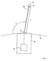
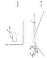
- a vehicle 10 carries at its front a laser scanner 12 and a connected via a data line to the laser scanner 12 data processing device 14, which forms together with the laser scanner 12, an apparatus for detecting and tracking objects according to a first preferred embodiment of the invention.
- a vehicle 10 carries at its front a laser scanner 12 and a connected via a data line to the laser scanner 12 data processing device 14, which forms together with the laser scanner 12, an apparatus for detecting and tracking objects according to a first preferred embodiment of the invention.
- Fig. 1 In the direction of travel in front of the vehicle is an in Fig. 1 only very schematically shown person 16, which is considered within the scope of the invention for the sake of simplicity as an object.
- the laser scanner 12 By means of the laser scanner 12 is an in Fig. 1 only partially shown detection range 18 scanned, which is due to the mounting position of the laser scanner 12 on the front side of the vehicle 10 is arranged symmetrically to the longitudinal axis of the vehicle 10 and covers an angle of slightly more than 180 °.
- the detection area 18 is in Fig. 1 shown only schematically and for clarity, especially in the radial direction too small.
- the laser scanner 12 scans its detection range 18 in a basically known manner with a pulsating laser beam bundle 20 rotating at a constant angular velocity, wherein the same time, at constant time intervals ⁇ t at times ⁇ i in fixed angle ranges around a mean angle ⁇ i , the laser radiation beam 20 is detected from a point 22 or area of an object, for example the person 16, is reflected.
- the index i runs from 1 to the number of angular ranges in the detection range 18. From these angle ranges is in Fig. 1 only an angular range is shown, which is associated with the mean angle ⁇ i . Here, however, the angle range is shown exaggerated for clarity.
- the detection area 18 is substantially two-dimensional, except for the widening of the laser beam 20, and essentially forms, i. to the diameter of the laser beam 20, a scanning plane.
- the distance d i of the object point 22 is determined by the laser scanner 12.
- the laser scanner 12 therefore detects, as coordinates in a distance pixel corresponding to the object point 22 of the object or the person 16, the angle ⁇ i and the distance d i determined at this angle, ie the position of the object point 22 in polar coordinates. Each detected object point is therefore assigned a distance pixel.
- the amount of range pixels acquired in the one scan forms a range image in the sense of the present application.
- the laser scanner 12 scans the detection area 18 in successive scans with time intervals ⁇ t, so that a temporal sequence of scans and corresponding distance images arises.
- the processing of the distance images of the laser scanner 12 is carried out by the data processing device 14.
- the data processing device 14 has u.a. via a digital signal processor programmed for carrying out the method according to the invention with a corresponding computer program according to the invention and a memory device connected to the digital signal processor.
- the data processing device may also have a conventional processor with which a computer program according to the invention stored in the data processing device is executed for carrying out the method according to the invention.
- the programmed data processing device provides means for evaluating current images of the sensor, means for determining parts of a current image as a result of at least preliminary evaluation of the current image or for recognizing an object in the current cycle and means for assigning parts of a current image previous image and / or for determining at least one indication relating to an earlier state of the object or an object corresponding thereto on the basis of a corresponding earlier image and assignment of the information to the part of the current image or the current object.
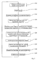
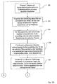
- the in Fig. 2 illustrated method performed according to a first preferred embodiment of the invention.
- a range image is acquired by scanning the detection area 18 and read into a memory in the data processing device 14.
- step S 10 a preprocessing of the distance image data is carried out, in which, optionally after correction of the data, a transformation of the position coordinates of the distance image points into a Cartesian, permanently connected to the vehicle 10 vehicle coordinate system is performed.
- step S 12 the distance image is then segmented.
- sets of range pixels are formed in a manner known per se, which are characterized in that each range pixel of an amount of at least one other range pixel of the same quantity has a mean square distance that is smaller than a predetermined segmentation distance.
- An amount thus formed corresponds to one segment each.
- a segment can also be formed by a single distance pixel, which has a mean square distance of all other distance pixels of the current distance image, which is greater than the predetermined segmentation distance.
- step S14 which is not performed in the very first cycle of the method, then an assignment of segments to objects already detected in an earlier cycle of the method takes place, by which methods known per se can be used. In the present method, this is done for each object known in the previous cycle used an object position predicted in step S28 of the previous cycle.
- a segment of the current cycle is assigned to a corresponding object of the previous cycle if at least one of the range pixels of the segment from the object in the predicated object position has a distance less than one of an uncertainty of prediction and magnitude and Orientation of the object in the previous cycle dependent maximum distance.
- step S 16 new objects are then formed from segments which could not be assigned to objects known from the previous cycle, and a position of the object in the current cycle is determined from the positions of the distance pixels constituting the segments.
- step S 18 after checking whether new objects have been found, it is checked whether in the preceding cycle a subject corresponding to a newly formed object in a previous range image or cycle may be recognized by an already recognized one in the previous cycle Object corresponding object could be obscured.
- the processing of the current distance image in steps S 10 to S 16 including the check in step S 18 whether a new object has been found represents an at least preliminary evaluation of the current image.
- FIGS. 3A and 3B This is exemplary in the FIGS. 3A and 3B in which in sections of successive distance images, a vehicle 24, which is only partially represented by the black solid line, and a symbolized by a rectangle 26 pedestrian, which moves at a speed v with respect to the vehicle 24 are shown.
- the individual points represent distance pixels of the corresponding distance images.
- the laser scanner 12 in the coordinate origin, ie in the point (0,0), wherein the coordinate axes of the Cartesian coordinate system in any, but fixed selected distance units are divided.
- FIG. 3A a previous distance image
- the pedestrian 26 is hidden from view of the laser scanner 12 of the vehicle 24 and therefore not detectable in the distance image.
- Fig. 3B in which the current distance image is shown, the pedestrian 24 has moved away behind the vehicle 24 and is now detected by the laser scanner 12 for the first time.
- the contours of the objects corresponding to the objects 24 and 26 are in FIGS. 3A and 3B each with a dashed line Compensation curve given by the distance pixels. It is easy to see that in Fig. 3B the contour of the vehicle 24 corresponding object is greater than that of the pedestrian 26 corresponding object.
- the further detection of occlusion preferably takes place adaptive to the situation, ie as a function of the speeds of the already recognized objects in the preceding cycle.
- the pedestrian 26 corresponding object can be found or no other object has a smaller distance to this and the pedestrian 26 corresponding object due the size may not correspond to a very fast moving object, the article or pedestrian 26 in the earlier image was very likely to be obscured by the vehicle 24.
- step S20 the location of objects covered in the previous range image of hidden objects corresponding to new objects is estimated as an indication with respect to an earlier state of the respective new objects according to the invention.
- a minimum speed of the object or pedestrian 26 is used to estimate the position in the previous distance image in Fig. 3A
- the subject or pedestrian 26 was just not visible at the time the range image was acquired, so that an object box surrounding it in the current range image, whose size is specified in the pedestrian-type object method, just does not have its edge laser radiation beam 20 could be detected.
- the results in Fig. 4 the estimated position of the pedestrian 26 given by the dotted rectangle in the previous distance image or cycle shifted by the displacement vector d from the position in the current distance image or cycle.
- step S22 the velocity of the objects is then estimated by determining the change in the location of an object in the previous image and the current image, using the estimated location for the new objects if they were obscured.
- the estimated velocity of the objects then results both with respect to the direction and the magnitude of the velocity by dividing the change in position given by the displacement vector d by the time duration ⁇ t between successive scans of the detection region 18.
- step S24 the determined object positions and sizes and the current distance image, which must be available in the following cycle as the then preceding distance image, are then stored, whereby the preceding distance image is deleted.
- step S26 the object positions and speeds are output to corresponding further processing devices.
- step S28 a prediction of new object positions for the following cycle is performed at the end of the current cycle.
- the prediction of the position of the object as well as the determination of the uncertainty of the prediction can be done for example in a known manner by means of a Kalman filter.
- initialization of the Kalman filter for this object can be done with much more accurate data, which greatly facilitates subsequent object recognition and tracking.
- step S10 Thereafter, the next cycle may begin with step S10.
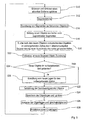
- a method for recognizing and tracking objects according to a second preferred embodiment of the invention is schematically illustrated in the flowchart in FIG Fig. 5 shown. It differs from the method according to the first embodiment in that newly detected objects are treated differently in a current cycle, so that the steps S 10 to S 16 and S22 to S28 are the same as in the above-described embodiment and the embodiments there apply accordingly also here.
- the apparatus for tracking and recognizing objects with the method according to the second preferred embodiment of the invention is only so compared with the corresponding apparatus in the first embodiment changed that the processed in the data processing device 14 program is modified accordingly, ie in particular that the means for assigning parts of an earlier image and / or for determining at least one indication with respect to a previous state of the object or a corresponding item on the Based on a corresponding earlier image and assignment of the specification to the part of the current image or the current object, are modified.
- step S30 after the formation of new objects from previously unallocated segments in step S 16 in step S30, after checking the criterion, whether a new object has ever been found in the current one , searched for the new objects corresponding objects or objects in the previous distance image. It is assumed that the new object could not be found in the previous cycle or distance image because it could not be recognized as an independent object due to the segmentation and object formation or segment-object assignment.
- FIGS. 6A to 6G illustrates in each of which sections of successive distance images are shown.
- the laser scanner 12 is again arranged in the distance images in the origin (0,0) of the coordinate system, which corresponds to the Cartesian coordinate system of the previous embodiment.
- a pedestrian 26 moves from the perspective of the laser scanner 12, initially immediately in front of a parked vehicle 24 at a speed v to get into the Figs. 6F and 6G finally to be removed from the vehicle 24 so far that it can be recognized as a stand-alone object with the normal segmentation method.
- the segmentation can not separate the distance pixels corresponding to the vehicle 24 from the range pixels corresponding to the pedestrian 26.
- the objects are determined which correspond to the new object corresponding to the pedestrian 26 in the current, the distance image in FIG Fig. 6F the next cycle. In the example, this is only the object corresponding to the vehicle 24.
- the steps up to this stage correspond to an at least preliminary evaluation of the current distance image in the sense of the invention.
- the range pixels of the segments in the previous range image or cycle are re-segmented to form the respective objects previously re-segmented in the previous cycle.
- these are all distance pixels of the section of the distance image in Fig. 6E .
- the segmentation method used in step S 12 is used, but with a reduced segmentation distance.
- the segmentation distance can be fixed.
- the segmentation distance is selected as a function of the detected size of at least one of the detected objects, preferably of the smallest, so that a situationally adapted segmentation can take place.
- step S32 a new assignment of segments to the objects affected by the re-segmentation is performed in step S32.
- objects already known in the previous cycle their position and speed in the preceding cycle are used in conjunction with the orientation, shape and size determined in the current cycle as well as for the new object of its shape and size determined in the current cycle.
- step S34 it is then checked whether new or changed objects were found in the preceding distance image. If this is not the case, the method is continued with step S22.
- step S36 a location of the object corresponding to the new object and the changed object in the preceding distance image is determined.
- the new object is then treated as a known object whose location in the previous cycle is known, for which purpose corresponding changes in data structures of the program are carried out and a corresponding Kalman filter for the previous cycle is subsequently initialized. Furthermore, for the changed object re-prediction of the location for the current cycle done to improve the accuracy of the Kalman filter.
- object positions for the preceding cycle and the current cycle are obtained for objects known in the previous cycle and newly found in step S32, so that an estimate of the velocity of these objects can now be made in step S22, the object positions in the preceding one Distance image or cycle can be used.
- the methods of the first two embodiments can be combined. For example, only a test according to Step S30 and, if no new objects were found in step S34, concealment detection according to the first embodiment.
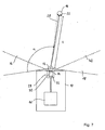
- a vehicle 10 which carries an apparatus for detecting and tracking objects according to a third preferred embodiment of the invention.
- the device for detecting and tracking objects differs from the device for detecting and tracking objects in the first embodiment in that in addition to the laser scanner 12, a video system 30 is provided which, like the laser scanner 12, via a corresponding data connection with a is compared to the data processing device 14 in the first embodiment modified data processing device 14 'is connected.
- a video system 30 is provided which, like the laser scanner 12, via a corresponding data connection with a is compared to the data processing device 14 in the first embodiment modified data processing device 14 'is connected.
- the video system 28 has a monocular video camera 30, which is a conventional black-and-white video camera having a CCD area sensor 32 and an imaging device incorporated in the Fig. 7 and 8th is shown schematically as a simple lens 34, but in fact consists of a lens system, and from a detection range 36 of the video system incident light on the CCD area sensor 32 images.
- An optical axis 38 of the video camera 30 is in a small, in Fig. 8 exaggeratedly large angle shown on the through the pivoting plane of the laser beam bundle 20 given scanning plane 40 of the laser scanner 12 to inclined.
- the CCD area sensor 32 has arrayed photodetection elements that are cyclically read to form video images with video pixels.
- the video images initially contain, for each pixel, the position of the photodetection elements in the matrix or a different identifier for the photodetection elements and a respective intensity value corresponding to the intensity of the light received by the corresponding photodetection element.
- the video images are acquired substantially synchronously with the distance images and thus at the same rate with which distance images are also acquired by the laser scanner 12.
- the focal length can be calculated from the location of an object point, such as the object point 22 on the person 16, on which location of the CCD Flat sensor 32 and which of the arranged as a matrix photodetection elements of the object point is mapped.
- the position of a photodetection element may be indicated by the short dashed lines in FIG Fig. 7 and Fig. 8 indicated light cone in which object points or areas must lie, from which detected radiation can fall on the photodetection element.
- a corresponding camera model can be used.
- the example is a well-known pinhole camera model.
- a common detection area 42 is in the Fig. 7 and 8th schematically represented by a dotted line and given by the section of the detection area 18 of the laser scanner 12 and the detection area 36 of the video system 28.
- the data processing device 14 'differs from the data processing device 14 on the one hand in that interfaces are provided to be substantially synchronous, ie within a time period that is significantly shorter than the time period ⁇ t between successive scans of the detection area 18 of the laser scanner 12, respectively To read in distance image and a current video image of the video system 28.
- the processor is programmed with a computer program according to a third preferred embodiment of the invention for carrying out a method according to a third preferred embodiment of the invention.
- the data processing device 14 comprises means for evaluating current images of the sensor, means for determining parts of a current image as a result of at least preliminary evaluation of the current image or for detecting an object in the current cycle and means for assigning parts of an earlier image and or for determining at least one indication relating to an earlier state of the object or an object corresponding thereto on the basis of a corresponding state previous image and assignment of the indication to the part of the current image or the current object in the sense of the invention.
- the in Fig. 9 illustrated method performed according to the third preferred embodiment of the invention.
- features in the video images are recognized and tracked, but video image processing is done on the basis of distance images for computation time by searching for features only in those portions of the video image in which range pixels of the range image and corresponding subject areas are located.
- step S38 a current distance image and a current video image are read in and preprocessed.
- the reading and the preprocessing of the images can be carried out independently of each other for the two images in parallel or in any order.
- the positional pixels in the distance image are supplemented by a positional component determined by the scanning plane 40 in which the object points corresponding to the distance picture elements form to form a complete positional coordinate set in three dimensions. With the location of a distance pixel, the position defined by these coordinates will be referred to below.
- the data of the video image is transformed into the vehicle coordinate system in which the distance pixels are also defined.
- a rectification of the video image data for example for the removal of distortions, and a transformation of the video pixels to an image plane is performed.
- the video pixels can then be assigned positions in the vehicle coordinate system in a corresponding plane.
- the current distance image and the current video image are stored for further use.
- step S 12 as in the first embodiment, the range image is then segmented.
- step S40 features are detected in the video image, wherein only areas are used by the video image in which the distance image according to a segment in the distance image corresponding object must be detectable. More precisely, the detection takes place only in strips of the video image which extend substantially perpendicular to the scanning plane of the laser scanner 12 and which in each case correspond to a segment of the distance image and which have video image points corresponding to the distance pixels in the segments.
- the strips are defined to extend in a direction orthogonal to the scanning plane 40 of the laser scanner 12 over the entire extent of the video image and have a width in the orthogonal direction determined to be the same for all the distance pixels of a segment corresponding video pixels in the respective Stripes lie. These video pixels can be determined by using the camera model.
- the strips each have predetermined edge areas in width on both sides of the respective outermost video picture elements. Since other parts of the video image are initially ignored, there is an attention control of the video image processing.
- an assignment in the features found in the current video image to characteristics known from the previous cycle continues to take place using a position of the respective features predicted in each case for the current cycle in step S49 of the preceding cycle.
- positions of the features in the current cycle are determined.
- step S41 it is then checked whether new features were found that could not be assigned to features not known from the previous cycle.
- step S42 a search is performed in step S42 for features corresponding to the new features in the preceding video image by a backward tracking.
- known methods of video image processing can be used.
- step S44 the location of a feature corresponding to the new feature in the previous video image is then determined.
- the determined feature locations and speeds are then output in step S26 after storage for further use.
- step S48 the current video image is then stored after the previous video image has been deleted.
- step S49 new feature layers are now predicted, so that an assignment of features in step S40 in the following cycle to objects is facilitated.
- the now known speeds or a Kalman filter can be used.
- a subsequent or supplementary evaluation of a preceding video image thus takes place.
- the results of this evaluation, the feature found or its location in the previous video image, are then used in the current cycle to determine the speed of the current feature.
- Figs. 10A and 10B and Figs. 11A and 11B The use of the method for the detection of suddenly behind parked vehicles prominent pedestrians is in the Figs. 10A and 10B and Figs. 11A and 11B, respectively.
- the Fig. 10A and 11A each show a section of successive, of the laser scanner 12th detected distance image at the level of the scanning plane 40, while the Fig. 10B and 11B Extracts from correspondingly substantially synchronously recorded with the video system 28 video images.
- the scanning plane 40 of the laser scanner 12 is shown by a dotted line. Furthermore, this corresponds to the Figs. 10A and 10B used Cartesian coordinate system in the previous embodiments.
- the pedestrian as in the Figs. 10A and 10B shown not detectable by the laser scanner 12, since it is covered by the vehicle 44.
- the detection area 36 of the video system 28 in the direction perpendicular to the scanning plane 40 has a larger opening angle than the detection area 18 of the laser scanner 12, the pedestrian 46 can already be seen in the corresponding video image. Due to the attention control, however, this is not detected in the video image since it is displayed in the distance image (cf. Fig. 10A ) is covered.
- the pedestrian 46 moves in the example at a speed v to the right, he is no longer covered by the vehicle 44 after some time, resulting in the Figs. 11A and 11B is shown.
- the pedestrian 46 can be detected in the range image so that it is also detected in the video image via the attention control. While nothing would be known about this in a conventional video image processing other than the location of the pedestrian 46, in the method traced in the video images of the embodiment of the pedestrian 46, where he in the in Fig. 10B shown video images can be recognized.
- the position thus determined in the earlier video image now makes it possible to determine the speed of the pedestrian 46, which was initially recognized only in the current video image, even at its first detection or recognition. Since the tracing only occurs when finding new features, the execution speed of the method is only slightly reduced on average.
- substantially the same object recognition and tracing apparatus as in the third embodiment is used, but the programming of the data processing means 14 'according to the changed method is also changed.
- This also means that the means for assigning parts of an earlier image and / or for determining at least one indication with respect to an earlier state of the object or an object corresponding thereto on the basis of a corresponding earlier image and assignment of the indication to the part of current picture or the current object are modified.
- range pixels in successively acquired range images are tracked using the optical flux in corresponding areas in video images acquired substantially synchronously with the range images.
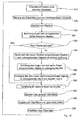
- step S50 of a current cycle a current distance image and a current video image are first acquired and read into the data processing device in which preprocessing of these images takes place in accordance with step S38 in the preceding embodiment.
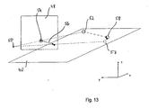
- the transformation of the video pixels is modified from the step S38 in the previous embodiment in that the transformation of the video pixels to an image plane 48 used for defining or calculating an optical flow (cf. Fig. 13 ) is carried out.
- a modified pinhole camera model for the video camera 30 which is basically known to the person skilled in the art is used, which is characterized by the position of an optical center 50 and the image plane 48 is defined, which serves as a surface for defining or determining the optical flow.
- the location of the optical center 50 is determined using the imaging geometry of the video camera 30, in particular the position relative to the laser scanner 12 and the focal length of the lens 34, determined.
- the pinhole camera model is modified for simplicity in that the image plane 48 is located at a fixed position between the optical center 50 and the object points, relative to the video system 28 on the vehicle 10 Fig. 13 the points 52 and 58, and by mirroring the actual image plane at the optical center 50 emerges from this.
- step S52 which is omitted in the first cycle of the method, first all distance pixels of the cycle immediately preceding the current cycle are determined which correspond to objects that are removed from the sensor or laser scanner 12. For the sake of simplicity, these distance pixels are referred to as removal pixels corresponding distance pixels.
- corresponding distance image points from the cycle directly preceding the current cycle are then calculated and stored for use in the current cycle in the image plane corresponding to respective video image points in the image plane 48.
- Fig. 13 illustrates geometrically, the position results in each case by the intersection 54 of an extending through the distance pixel, in the distance pixel 52, and the optical center 50 degrees with the image plane 48th
- step S54 which is likewise omitted in the first cycle, then for all projected distance pixels of the preceding cycle or corresponding intersections corresponding to the objects moving away from the laser scanner 12, corresponding actual optical flow vectors, hereinafter also referred to as optical flows, determined on the basis of the video image from the immediately preceding cycle and from the current cycle and converted by multiplication with the cycle duration or the reciprocal of the sampling frequency into a displacement vector.
- Fig. 13 this is shown for the range pixel 52, for which at the intersection 54 an optical flux vector is determined which lies in the image plane 48 and which, after scaling with the cycle time, results in a displacement vector 56 beginning at the intersection 54.
- optical flow is determined by means of a differential method, in this example the " Performance of optical flow techniques "by JL Barren, DJ Fleed and SS Beauchemin, International Journal of Computer Vision, 12 (1), pp. 43-77 (1994) described by Luke and Canade.
- a position of a corresponding object point predicted by the optical flow in the current cycle in the scanning plane 40 is then determined in step S56.
- Geometric in Fig. 13 For this purpose, the intersection point 57 of a straight line passing through the optical center 50 and the end point of the displacement vector 56 with the scanning plane 40 is determined.
- step S58 current distance pixels, in Fig. 13
- the current range pixel 58 the current range image associated with predicted locations and corresponding distance pixels of the previous image or cycle, if possible.
- an assignment criterion for example, can be used are assigned to the one current distance pixel whose quadratic distance between the predicted position and the actual current position is minimal compared to those of other current range pixels.
- step S60 the unassigned distance pixels of the current cycle, which must therefore correspond to objects not removing from the laser scanner 12, are projected onto the image plane 48, which is analogous to the projection in step S52.
- optical flows are then calculated in step S62 analogously to step S54.
- a traced position of a corresponding object point in the scanning plane 40 is now determined in step S64.
- the determination of the traced position is carried out analogously to the determination of the predicted position in step S56, but as a displacement vector, a corresponding opposite to the optical flow corresponding vector is used.
- step S66 then an assignment of distance pixels of the previous cycle, which correspond to non-sensor-removing objects, then predetermined, traced layers and corresponding unassigned distance pixels of the current cycle in step S64.
- the assignment can be made according to a corresponding scheme, as in step S58, but now predetermined distance pixels of the current cycle or corresponding traced layers are assigned distance pixels of the previous distance image.
- distance pixels of the previous cycle and of the current cycle or image are assigned to one another, wherein the assignment for objects removing from the laser scanner 12 takes place such that current range pixels are assigned to range pixels of the preceding frame while the remaining range pixels of the preceding frame which are not assigned to objects removing from the sensor or laser scanner 12, are assigned to the unassigned distance pixels of the current cycle and distance image or their traced layers.
- step S68 a segmentation of the current distance image corresponding to the segmentation in step S 12 of the first embodiment is now performed.
- step S70 a segment-object mapping is then performed using the association of range pixels of the previous range image and the current range image and the association between range pixels of the previous range image and objects of the previous cycle.
- step S72 object properties, in particular their positions and speeds, are determined and output.
- the method may then proceed to step S50 in the next cycle.
- a prediction step can be eliminated by using the optical flow.
- the projection can be done in other ways, examples of which are described in the aforementioned patent application.
- a corresponding device for object recognition and tracking according to a fourth preferred embodiment of the invention therefore comprises a video system as used in the previous embodiment and the preceding other method, the video camera of which is connected to a data processing device as in the previous embodiment and the preceding other method, but which are suitable for carrying out the method is programmed according to the fourth preferred embodiment.
- This also means that the means for assigning parts of an earlier image and / or for determining at least one indication with respect to an earlier state of the object or an object corresponding thereto on the basis of a corresponding earlier image and assignment of the indication to the part of current picture or the current object are modified.
- the laser scanner 12 is eliminated.
- a current video image is first detected and read in step S74 in a current cycle.
- a corresponding preprocessing of the video image data can take place.
- step S76 in order to increase the processing speed, the read-in video image is subjected to image resolution reducing filtering, which in the present embodiment consists of using only the pixel in the lower left corner of 4x4 blocks of video pixels.
- step S78 then objects in the subsampled video image are detected.
- conventional methods of object recognition and tracking in video images can be used.
- step S80 the detected objects are now assigned to objects from the previous cycle.
- the assignment is made in the example based on predicted object positions for the current cycle, which were determined in the previous cycle in a step S94, by means of known association methods.
- step S82 it is checked whether new objects were detected which were not to be assigned to any of the objects of the previous cycle. If no new objects were detected, the process continues to step S90.
- step S84 in the previous video image which is not sub-sampled in the example or half as strong as the image generated in step S76, is searched for an object that corresponds to a new object.
- FIG. 15A For example, the person is schematically represented in a current full resolution video image, with black rectangles representing video pixels corresponding to the person. Due to the above-mentioned subsampling, the in Fig. 15B shown subsampled video image in which the person is represented only by four individual pixels. If the person has now approached the video camera from a greater distance, it can do so in the previous one Video image at full resolution, for example, the in Fig. 16 shown size, wherein after subsampling no pixel survives, by means of which a corresponding object could be detected.
- the new object is searched for in the previous image in full resolution and not in the reduced resolution, which therefore can also be found. Nevertheless, since the new object can only occur near the object detected in the current video image, the computation time for recognizing the object in the previous video image is greatly reduced.
- step S88 the objects corresponding to the new objects in the previous video image are tracked into the current cycle, which is easily possible since the corresponding object has already been detected in the subsampled current video image.
- step S90 Based on the determined positions of the objects in the preceding video image and thus in the previous cycle and in the current cycle, it is now possible to determine speeds of the objects by estimation or difference formation in step S90.
- step S92 the current video image is then stored, erasing the previous video image.
- step S94 an output of the object positions and velocities is made for use in the following applications.
- step S96 new object locations are predicted for the following cycle, in the vicinity of which objects in the video image of the following cycle are searched for.
- a Kalman filter can be used again.
- the method according to the fourth embodiment allows on the one hand by the sub-sampling a high execution speed.
Landscapes
- Engineering & Computer Science (AREA)
- Physics & Mathematics (AREA)
- General Physics & Mathematics (AREA)
- Remote Sensing (AREA)
- Radar, Positioning & Navigation (AREA)
- Multimedia (AREA)
- Theoretical Computer Science (AREA)
- Computer Networks & Wireless Communication (AREA)
- Electromagnetism (AREA)
- Computer Vision & Pattern Recognition (AREA)
- Image Analysis (AREA)
- Optical Radar Systems And Details Thereof (AREA)
- Geophysics And Detection Of Objects (AREA)
- Burglar Alarm Systems (AREA)
- Radar Systems Or Details Thereof (AREA)
Abstract
Description
Die vorliegende Erfindung betrifft ein Verfahren zur Erkennung und Verfolgung von Objekten, die Gegenständen in einem Erfassungsbereich eines Sensors für elektromagnetische Strahlung entsprechen, sowie eine Vorrichtung zur Durchführung des Verfahrens.The present invention relates to a method for detecting and tracking objects that correspond to objects in a detection range of an electromagnetic radiation sensor, and to an apparatus for performing the method.
Verfahren zur Erkennung und Verfolgung von Objekten sind grundsätzlich bekannt. Typischerweise werden dabei in konstanten Zeitabständen Bilder eines Erfassungsbereichs durch einen Sensor für elektromagnetische Strahlung, beispielsweise einen Laserscanner oder eine Videokamera, erfasst. In den Bildern wird dann nach Objekten gesucht, die Gegenständen in dem Erfassungsbereich entsprechen. Wurde in einem Bild ein Objekt erstmals gefunden, wird in nachfolgenden Zyklen des Verfahrens nach diesem Objekt gesucht, um dessen Lage bzw. Lageänderung im Laufe der Zeit verfolgen zu können. Dazu wird häufig ausgehend von der Lage und Geschwindigkeit eines Objekts in einem vorhergehenden Zyklus dessen Lage für einen aktuellen Zyklus bzw. in einem aktuellen Bild prädiziert, um dann in dem Bild in der Nähe der prädizierten Lage des Objekts aufgefundene Elemente, beispielsweise Segmente, dem Objekt aus dem vorhergehenden Zyklus zuordnen und so dessen aktuelle Lage erfassen zu können.Methods for detecting and tracking objects are known in principle. Typically, images of a detection area are detected at constant time intervals by a sensor for electromagnetic radiation, for example a laser scanner or a video camera. The images are then searched for objects that correspond to objects in the detection area. If an object was found for the first time in a picture, this object is searched for in subsequent cycles of the method in order to be able to track its position or positional change over time. This is often predicated on the basis of the position and speed of an object in a previous cycle, its location for a current cycle or in a current image, then then found in the image in the vicinity of the predicated position of the object elements, such as segments, the object from the previous cycle and to be able to record its current position.
Solche Verfahren eignen sich beispielsweise zur Überwachung eines Bereichs vor und/oder neben einem Kraftfahrzeug. Ein möglicher Vorteil einer solchen Überwachung kann darin liegen, dass plötzlich auftretende Gefahren automatisch erkannt und entsprechende Gegenmaßnahmen eingeleitet werden können. Dazu ist es allerdings notwendig, dass Objekte sehr schnell erkannt und genau verfolgt werden können.Such methods are suitable, for example, for monitoring an area in front of and / or next to a motor vehicle. A potential advantage Such monitoring can be the automatic detection of sudden dangers and the introduction of appropriate countermeasures. For this purpose, however, it is necessary that objects can be detected very quickly and accurately tracked.
Bei den oben erwähnten Verfahren wird mit zunehmender Dauer der Verfolgung eines Objekts häufig die Genauigkeit der erfassten Objekteigenschaften zunehmen, da im Verlauf der Verfolgung weitere Informationen über das Objekt gesammelt werden können, die eine bessere Charakterisierung des Objekts bzw. des Zustands des Objekts erlauben. Dementsprechend können Ungenauigkeiten insbesondere dann auftreten, wenn in Bildern neue Objekte auftreten. Im Beispiel des Kraftfahrzeugs kann es sich hierbei beispielsweise um Fußgänger handeln, die, verdeckt durch einen anderen Gegenstand wie beispielsweise ein an einem Fahrbahnrand parkendes Kraftfahrzeug, plötzlich auf die Straße treten und erst dann von dem Sensor erfassbar werden. Das gleiche Problem kann auftreten, wenn Fußgänger vor einem Gegenstand so positioniert sind, dass das Objektverfolgungsverfahren den Fußgänger und den Gegenstand zu einem Objekt zusammenfasst, so dass der Fußgänger auch erst erkannt wird, wenn er sich weit genug von dem Gegenstand entfernt hat.In the above-mentioned methods, as the duration of the tracking of an object increases, the accuracy of the detected object properties will often increase, as in the course of the tracking, further information about the object can be collected allowing for better characterization of the object or state of the object. Accordingly, inaccuracies may occur especially when new objects appear in images. In the example of the motor vehicle, this may be, for example, pedestrians who, covered by another object such as, for example, a motor vehicle parked on the edge of a roadway, suddenly appear on the road and can only then be detected by the sensor. The same problem can occur when pedestrians are positioned in front of an object so that the object tracking process combines the pedestrian and the object into an object so that the pedestrian is not recognized until he has moved far enough away from the object.
Der vorliegenden Erfindung liegt die Aufgabe zugrunde, ein Verfahren zur Erkennung und Verfolgung von Objekten, die Gegenständen in einem Erfassungsbereich eines Sensors für elektromagnetische Strahlung entsprechen, bereitzustellen, das eine schnelle Erkennung und Verfolgung von Objekten erlaubt, sowie eine entsprechende Vorrichtung zur Durchführung des Verfahrens zu schaffen.It is an object of the present invention to provide a method for detecting and tracking objects corresponding to objects in a detection area of an electromagnetic radiation sensor, which allows rapid detection and tracking of objects, and a corresponding apparatus for performing the method create.
Die Aufgabe wird gelöst durch ein Verfahren mit den Merkmalen des Anspruchs 1.The object is achieved by a method having the features of
Bei dem erfindungsgemäßen Verfahren zur Erkennung und Verfolgung von Objekten, die Gegenständen in wenigstens einem Erfassungsbereich wenigstens eines Sensors für elektromagnetische Strahlung entsprechen, auf der Basis von wiederholt mittels des wenigstens einen Sensors erfassten Bildern des Erfassungsbereichs werden in aufeinanderfolgenden Zyklen aufeinanderfolgende Bilder ausgewertet und es wird jeweils wenigstens ein in einem Zyklus auf der Basis eines entsprechenden Bildes aufgefundenes Objekt in einem späteren Zyklus in einem entsprechenden späteren Bild gesucht, um das Objekt zu verfolgen. Es wird bei Erkennung eines neuen Objektes und/oder Merkmals in einem aktuellen Zyklus auf der Basis der Ergebnisse einer wenigstens vorläufigen Auswertung eines aktuellen Bildes während wenigstens eines aktuellen Zyklus wenigstens einem in dem aktuellen Zyklus ermittelten Teil eines aktuellen Bildes oder einem in dem aktuellen Zyklus erkannten Objekt wenigstens ein Teil eines früheren Bildes und/oder wenigstens eine Angabe in Bezug auf einen früheren Zustand des Objekts oder eines diesem entsprechenden Gegenstands, die unter Verwendung eines entsprechenden früheren Bildes in dem aktuellen Zyklus ermittelt wird, zugeordnet.In the method according to the invention for detecting and tracking objects which correspond to objects in at least one detection region of at least one electromagnetic radiation sensor, on the basis of images of the detection region repeatedly captured by the at least one sensor, successive images are evaluated in successive cycles, and in each case searched at least one object found in a cycle on the basis of a corresponding image in a later cycle in a corresponding later image to track the object. It is detected upon detection of a new object and / or feature in a current cycle based on the results of at least preliminary evaluation of a current image during at least one current cycle of at least one part of a current image detected in the current cycle or one recognized in the current cycle Object is associated with at least a portion of an earlier image and / or at least one of an earlier state of the object or an object corresponding thereto determined using a corresponding previous image in the current cycle.
Die Aufgabe wird weiterhin gelöst durch eine Vorrichtung mit den Merkmalen des Anspruchs 13.The object is further achieved by a device having the features of
Die erfindungsgemäße Vorrichtung zur Erkennung und Verfolgung von Objekten weist mindestens einen zur Erfassung von Bildern eines Erfassungsbereichs ausgebildeten Sensor für elektromagnetische Strahlung und eine mit dem zumindest einen Sensor verbundene Datenverarbeitungseinrichtung auf, die zur Durchführung des erfindungsgemäßen Verfahrens ausgebildet ist und insbesondere Mittel zur Auswertung aktueller Bilder des zumindest einen Sensors, Mittel zur Ermittlung von Teilen eines aktuellen Bildes als Ergebnis einer wenigstens vorläufigen Auswertung des aktuellen Bildes oder zur Erkennung eines Objekts in dem aktuellen zyklus und Mittel zur Zuordnung von Teilen eines früheren Bildes und/oder zur Ermittlung wenigstens einer Angabe in Bezug auf einen früheren Zustand des Objekts oder eines diesem entsprechenden Gegenstands unter Verwendung eines entsprechenden früheren Bildes in dem aktuellen Zyklus und Zuordnung der Angabe zu dem Teil des aktuellen Bildes oder dem aktuellen Objekt umfasst.The device according to the invention for detecting and tracking objects has at least one sensor for electromagnetic radiation, which is designed to detect images of a detection area, and a data processing device connected to the at least one sensor, which is designed to carry out the method according to the invention and in particular means for evaluating current images of the at least one sensor, means for determining parts of a current image as a result of at least preliminary evaluation of the current image or for detecting an object in the current cycle and means for assignment parts of an earlier image and / or for determining at least one indication of an earlier state of the object or an object corresponding thereto using a corresponding previous image in the current cycle and associating the indication with the part of the current image or the current object includes.
Das erfindungsgemäße Verfahren, das mittels der erfindungsgemäßen Vorrichtung durchführbar ist, dient zur Erkennung und Verfolgung von Objekten in einem Erfassungsbereich. Dieser kann grundsätzlich ortsfest sein oder sich bewegen, was insbesondere dann der Fall sein kann, wenn die Bilder mittels eines an einem Fahrzeug befestigten Sensors erfasst werden.The method according to the invention, which can be carried out by means of the device according to the invention, serves to detect and track objects in a detection area. This can basically be stationary or move, which can be the case in particular when the images are detected by means of a sensor attached to a vehicle.
Die Bilder werden von wenigstens einem Sensor für elektromagnetische Strahlung erfasst. Bei dem Sensor kann es sich um einen rein passiven Sensor handeln, der nur elektromagnetische Strahlung empfängt. Es kann jedoch auch ein Sensor verwendet werden, der über eine Quelle für insbesondere gerichtet, abstrahlbare elektromagnetische Strahlung, die von einem durch die Strahlung beleuchteten Punkt oder Bereich auf einem Gegenstand zurückgeworfen werden kann, und wenigstens einen entsprechenden für von einem Gegenstandspunkt oder -bereich zurückgeworfene Strahlung empfindliches Sensorelement verfügt. Weiterhin können auch Kombinationen von Sensoren für elektromagnetische Strahlung eingesetzt werden, die verschiedene Typen von Bildern erfassen. Die Erfassungsbereiche der Sensoren brauchen sich dann nicht unbedingt zu überschneiden, doch ist es bevorzugt, dass diese sich wenigstens teilweise überschneiden.The images are captured by at least one electromagnetic radiation sensor. The sensor may be a purely passive sensor that receives only electromagnetic radiation. However, a sensor may also be used which can be reflected by a source of particularly directional, radiatable electromagnetic radiation which can be reflected from an illuminated point or area on an object and at least one corresponding one reflected from an object point or region Radiation sensitive sensor element has. You can also continue Combinations of electromagnetic radiation sensors are used which detect different types of images. The detection ranges of the sensors then need not necessarily overlap, but it is preferred that these overlap at least partially.
Unter einem Bild wird dabei insbesondere auch eine Menge von Daten verstanden, die jeweils die Lage eines Punktes oder Bereichs auf einem oder mehreren von dem Sensor erfassten Gegenstand in wenigstens einer Richtung quer zu einer Sichtrichtung des Sensors und wenigstens eine Eigenschaft des Gegenstandspunktes oder -bereichs wiedergeben. Die Lage des Gegenstandspunktes kann dabei beispielsweise bei Erfassung von Gegenstandspunkten in einer Abtastebene durch einen Winkel gegenüber einer beliebigen, aber fest vorgegebenen Referenzrichtung, beispielsweise des Sensors, gegeben sein. Bei Erfassung von Gegenstandspunkten oder -bereich im Raum können die Lagen durch Lagen von Sensorelementen des Sensors und gegebenenfalls Abbildungseigenschaften gegeben sein. Bei der Eigenschaft kann es sich beispielsweise um die Intensität und/oder Wellenlänge bzw. Farbe der abgestrahlten optischen Strahlung, die Entfernung von dem Sensor oder auch die Geschwindigkeit in radialer Richtung relativ zu dem Sensor handeln. So können beispielsweise Videobilder Daten zur Intensität abgestrahlter optischer Strahlung als Eigenschaft und in Bezug auf ein Sensorelement, das die Strahlung eines Gegenstandspunktes oder -bereichs erfasst hat, und damit in Bezug auf eine Lage enthalten, während Entfernungsbilder als Eigenschaften der erfassten Gegenstandspunkte bzw. -bereiche die Entfernung von dem Sensor und als Lageinformation eine Winkel, unter dem der Gegenstandspunkt oder -bereich erfasst wurde, enthalten können. Geschwindigkeitsbilder enthalten schließlich Daten über die Geschwindigkeit der Gegenstandspunkte bzw. -bereiche relativ zu dem Sensor.In this context, an image is in particular also understood to mean a set of data which respectively reproduce the position of a point or area on one or more objects detected by the sensor in at least one direction transverse to a viewing direction of the sensor and at least one property of the object point or area , The position of the object point can be given, for example, when detecting object points in a scanning plane by an angle with respect to any, but fixed predetermined reference direction, for example, the sensor. Upon detection of object points or area in space, the layers may be given by layers of sensor elements of the sensor and optionally imaging properties. The property may be, for example, the intensity and / or wavelength or color of the emitted optical radiation, the distance from the sensor or also the speed in the radial direction relative to the sensor. For example, video images may contain data on the intensity of radiated optical radiation as a property and with respect to a sensor element that has detected the radiation of an object point or area, and thus with respect to a location, while range images as properties of the detected object points or areas the distance from the sensor and, as position information, may include an angle at which the subject point or range was detected. speed pictures Finally, data on the speed of the object points or areas relative to the sensor.
Die Bilder brauchen dabei nicht unmittelbar durch einen einzelnen Sensor erfasst zu sein. Vielmehr ist es auch möglich, wenigstens zwei zeitlich einander zugeordnete Bilder, die durch wenigstens zwei Sensoren für elektromagnetische Strahlung erfasst wurden, zu einem Gesamtbild zu kombinieren, das einen größeren Erfassungsbereich oder zusätzliche Eigenschaften von Gegenstandspunkten oder -bereichen wiedergibt. Beispielsweise können aus zwei Bildern, die von zwei beabstandet zueinander angeordneten Videokameras erfasst wurden, unter Beachtung der Abbildungseigenschaften und der Anordnung der Videokameras Entfernungsbilder erzeugt werden, die zusätzlich zu einer Entfernung eines Gegenstandspunkts bzw. -bereichs von einem relativ zu den Videokameras ortsfesten Bezugspunkt auch Daten in Bezug auf die Intensität bzw. Farbe des von dem jeweiligen Gegenstandspunkt bzw. -bereich abgegebenen Lichts aufweisen.The images need not be detected directly by a single sensor. Rather, it is also possible to combine at least two temporally associated images, which were detected by at least two electromagnetic radiation sensors, to form an overall image that reflects a larger detection area or additional characteristics of object points or areas. For example, from two images captured by two spaced-apart video cameras, taking into account the imaging characteristics and the arrangement of the video cameras, distance images may be generated which also include data in addition to a distance of an object point from a reference point fixed relative to the video cameras with respect to the intensity or color of the light emitted by the respective object point or area.
Weiterhin können auch verschiedene Typen von Bildern zu einem Gesamtbild kombiniert bzw. gemeinsam oder auch in Abhängigkeit voneinander verarbeitet werden. So können vorzugsweise Video- und Entfernungsbilder gemeinsam verarbeitet werden, ohne im engeren Sinne zu einem Satz von Bilddaten zusammengefasst zu werden.Furthermore, different types of images can be combined into an overall image or processed together or in dependence on each other. Thus, preferably video and distance images can be processed together, without being summarized in a narrow sense to a set of image data.
Die bei dem erfindungsgemäßen Verfahren verwendeten Bilder sind zu aufeinanderfolgenden Zeiten erfasst, wobei diese vorzugsweise einen konstanten zeitlichen Abstand voneinander aufweisen. Der Sensor der erfindungsgemäßen Vorrichtung ist daher zur wiederholten Erfassung von Bildern des Erfassungsbereichs abgebildet. Werden für einen Zyklus mehrere Bilder verwendet, sind diese vorzugsweise im Wesentlichen synchron erfasst, d.h. ihre Erfassungszeiten unterscheiden sich um eine kleinere Zeitspanne als die zwischen aufeinanderfolgenden Abtastungen durch den Sensor mit der geringsten Erfassungsrate.The images used in the method according to the invention are recorded at successive times, these preferably having a constant time interval from one another. The sensor of the device according to the invention is therefore for the repeated detection of Images of the coverage area shown. If several images are used for one cycle, they are preferably detected substantially synchronously, ie their detection times differ by a smaller time span than that between successive samples by the sensor with the lowest detection rate.
Die erfassten Bilder werden dann in aufeinanderfolgenden Zyklen ausgewertet, wobei in einem gegebenen Zyklus wenigstens ein entsprechendes Bild ausgewertet wird. Werden mehrere Bilder im Wesentlichen synchron erfasst, genügt, dass eines der Bilder wenigstens vorläufig ausgewertet wird.The acquired images are then evaluated in successive cycles, with at least one corresponding image being evaluated in a given cycle. If several images are recorded essentially synchronously, it is sufficient for one of the images to be evaluated at least provisionally.
Es wird jeweils wenigstens ein in einem Zyklus auf der Basis wenigstens eines entsprechenden Bildes aufgefundenes Objekt in einem späteren Zyklus in einem entsprechenden späteren Bild gesucht, um es zu verfolgen. Hierzu können insbesondere konventionelle Objekterkennungs- und -verfolgungsverfahren verwendet werden. In diesem Fall kann eine Zuordnung von Bildpunkten des aktuellen Zyklus zu in einem vorhergehenden Zyklus bzw. Bild erkannten Objekten erfolgen.In each case at least one object found in a cycle on the basis of at least one corresponding image is searched in a later cycle in a corresponding later image in order to be tracked. In particular, conventional object recognition and tracking methods can be used for this purpose. In this case, an assignment of pixels of the current cycle to objects detected in a previous cycle or image can take place.
Insbesondere kann ein Prädiktionsverfahren verwendet werden, bei dem auf der Basis der Lage wenigstens eines Objekts in einem früheren, insbesondere in einem vorhergehenden Zyklus und dessen Geschwindigkeit eine Lage in dem aktuellen Zyklus prädiziert wird und in der Umgebung der prädizierten Lage nach dem Objekt gesucht wird. Neue Objekte können aus Teilen eines Bildes, d.h. Bildpunkten oder in dem Zyklus ermittelte Mengen von Bildpunkten, insbesondere Segmente, gebildet werden, die nicht bereits bekannten Objekten zugeordnet werden konnten.In particular, a prediction method may be used in which a position in the current cycle is predicated on the basis of the position of at least one object in an earlier cycle, in particular in a preceding cycle and its velocity, and the object is searched for in the vicinity of the predicted position. New objects may be formed from portions of an image, ie, pixels or sets of pixels, in particular segments, determined in the cycle that could not be associated with previously known objects.
Erfindungsgemäß ist es nun abweichend von konventionellen Objekterkennungs- und -verfolgungsverfahren vorgesehen, dass während wenigstens eines aktuellen Zyklus auf der Basis der Ergebnisse einer wenigstens vorläufigen Auswertung eines aktuellen Bildes wenigstens einem in dem aktuellen Zyklus ermittelten Teil eines aktuellen Bildes oder einem in dem aktuellen Zyklus erkannten Objekt wenigstens ein Teil eines früheren Bildes und/oder wenigstens eine Angabe in Bezug auf einen früheren Zustand des Objekts oder eines diesem entsprechenden Gegenstands, die auf der Basis eines entsprechenden früheren Bildes ermittelt wird, zugeordnet wird.In accordance with the invention, unlike conventional object detection and tracking methods, it is contemplated that, during at least one current cycle, based on the results of at least preliminary evaluation of a current image, at least one portion of a current image determined in the current cycle or one recognized in the current cycle Object is associated with at least a portion of an earlier image and / or at least one of an earlier state of the object or an object corresponding thereto determined based on a corresponding earlier image.
Werden dabei mehrere im Wesentlichen synchron erfasste Bilder gleichen oder verschiedenen Typs verwendet, genügt es, dass eine vorläufige Auswertung eines dieser Bilder erfolgt, die Zuordnung kann zu Teilen des gleiche oder eines anderen, im Wesentlichen synchron erfassten Bildes erfolgen.If several essentially synchronously acquired images of the same or different type are used, it is sufficient for a provisional evaluation of one of these images to take place; the assignment can be made to parts of the same or another image recorded essentially synchronously.
Dies bedeutet, dass in einem aktuellen Zyklus nicht nur ein aktuelles Bild ausgewertet wird. Vielmehr wird zunächst die wenigstens vorläufige bzw. gegebenenfalls teilweise Auswertung eines aktuellen Bildes in dem aktuellen Zyklus durchgeführt. Auf der Basis dieser wenigstens vorläufigen Auswertung, d.h. insbesondere in Abhängigkeit von dem Resultat der wenigstens vorläufigen Auswertung, wird dann zur Objektverfolgung bzw. Ermittlung von Daten in Bezug auf ein Objekt ein früheres Bild verwendet, bei dem es sich insbesondere um ein unmittelbar vor dem aktuellen Bild erfasstes Bild, das einem vorhergehenden Zyklus zugeordnet ist, handeln kann.This means that not only a current image is evaluated in a current cycle. Rather, the at least provisional or possibly partial evaluation of a current image in the current cycle is first carried out. On the basis of this at least provisional evaluation, ie in particular depending on the result of the at least provisional evaluation, an earlier image is then used for object tracking or determination of data with respect to an object, which in particular is one immediately before the current one Image captured image associated with a previous cycle can act.
Bei der vorläufigen Auswertung kann insbesondere wenigstens ein Kriterium überprüft werden, an Hand dessen entschieden wird, ob ein früheres Bild verwendet werden soll oder nicht. Das bedeutet dann, dass bei Nichterfüllung des Kriteriums eine sonst bekannte Objekterkennung und -verfolgung erfolgen kann.In the preliminary evaluation, in particular at least one criterion can be checked, by means of which a decision is made as to whether an earlier image should be used or not. This then means that if the criterion is not met, an otherwise known object recognition and tracking can take place.
Bei der wenigstens vorläufigen Auswertung wird ein Teil eines aktuellen Bildes ermittelt, bei dem es sich um einen Bildpunkt oder eine in dem aktuellen Zyklus ermittelte Menge von Bildpunkten, beispielsweise wenigstens ein Segment, handeln kann. Werden in einem aktuellen Zyklus mehrere aktuellen Bilder verwendet, braucht dabei das Bild, das vorläufig ausgewertet wurde, nicht unbedingt mit dem Bild übereinzustimmen, von dem ein Teil ermittelt wird. Es kann jedoch auch ein Objekt in dem aktuellen Bild erkannt und verwendet werden. Sowohl die Ermittlung des Teils des Bildes als auch die Erkennung des Objekts kann dabei zunächst mit Verfahrensschritten erfolgen, die denen in konventionellen Verfahren gleichen.In the at least preliminary evaluation, a part of a current image is determined, which may be a pixel or a set of pixels, for example at least one segment, determined in the current cycle. If several current images are used in a current cycle, the image that has been preliminarily evaluated does not necessarily have to match the image from which a part is determined. However, an object in the current image can also be recognized and used. Both the determination of the part of the image and the recognition of the object can be carried out first with method steps that are similar to those in conventional methods.
Dem bei der wenigstens vorläufigen Auswertung ermittelten Teil des aktuellen Bildes oder dem Objekt in dem aktuellen Zyklus kann dann ein Teil des früheren Bildes zugeordnet werden, bei dem es sich wiederum um einen Bildpunkt oder eine in dem aktuellen Zyklus ermittelte Menge von Bildpunkten, beispielsweise wenigstens ein Segment, des früheren Bildes handeln kann. Dabei können die Teile der Bilder jeweils unterschiedliche Anzahlen von Bildpunkten aufweisen, so dass keine Eins-zu-Eins-Zuordnung von Bildpunkten gegeben zu sein braucht. Für beliebige erste und/oder zweite Objekte und/oder Teile von ersten und/oder zweiten Bildern wird dabei unter einer Zuordnung eines Teils eines ersten Bildes oder eines ersten Objekts zu einem Teil eines zweiten Bildes oder einem zweiten Objekt verstanden, dass der Teil des zweiten Bildes oder das zweite Objekt vorgegeben wird, und dafür ein geeigneter Teil eines ersten Teils oder ein geeignetes erstes Objekt aus gegebenenfalls mehreren Alternativen ausgesucht und zugeordnet wird.The part of the current image or the object in the current cycle determined in the at least preliminary evaluation can then be assigned a part of the previous image, which in turn is a pixel or a set of pixels determined in the current cycle, for example at least one Segment, the previous image can act. In this case, the parts of the images may each have different numbers of pixels, so that no one-to-one assignment of pixels needs to be given. For any first and / or second objects and / or parts of first and / or second In this case, images are understood to mean an assignment of a part of a first image or of a first object to a part of a second image or of a second object that specifies the part of the second image or the second object, and for this a suitable part of a first part suitable first object from possibly several alternatives selected and assigned.
Dem Teil des aktuellen Bildes oder dem Objekt in dem aktuellen Zyklus kann jedoch auch eine Angabe zugeordnet werden, die sich auf das Objekt bzw. einen diesem entsprechenden Gegenstand bezieht. Bei dieser Angabe kann es sich um Werte beliebiger Zustandsgrößen eines Objekts bzw. Gegenstands handeln, beispielsweise die Lage, Geschwindigkeit, Form, Größe, Zuordnung zu einer von mehreren Objektklassen, in die Objekte gemäß ihren für die Objektverfolgung relevanten typischen Eigenschaften eingeordnet werden, oder auch die Präsenz des Gegenstands überhaupt. Zur Ermittlung der Angabe braucht dabei nicht das gesamte frühere Bild verwendet zu werden, vielmehr kann sich die Ermittlung auch nur auf Teilbereiche beschränken. Jedoch wird zur Ermittlung immer unmittelbar wenigstens ein Bildpunkt des früheren Bildes, das dazu vorzugsweise noch während des aktuellen Zyklus gespeichert sein kann, und gleichzeitig das Ergebnis der wenigstens vorläufigen Auswertung des aktuellen Bildes verwendet.However, the part of the current image or object in the current cycle may also be assigned an indication relating to the object or object corresponding thereto. This information can be values of arbitrary state variables of an object or object, for example the position, speed, shape, size, assignment to one of several object classes, into which objects are classified according to their properties relevant for object tracking, or else the presence of the object at all. In order to determine the information, it is not necessary to use the entire previous image, but the determination can also be limited to subareas. However, at least one pixel of the previous image, which may preferably still be stored for this purpose during the current cycle, and at the same time the result of the at least preliminary evaluation of the current image are used for the determination.
In jedem Fall ist es wesentlich, dass ein Teil des früheren Bildes bzw. eine aus dem früheren Bild gewonnene Angabe einem Teil des aktuellen Bildes oder einem Objekt des aktuellen Zyklus zugeordnet werden und nicht Teile des aktuellen Bildes Objekten oder Angaben, die aus dem früheren Bild gewonnen wurden.In any case, it is essential that a portion of the previous image or an item derived from the previous image be associated with a portion of the current image or an object of the current cycle and not portions of the current image with objects or indicia derived from the previous image were won.
Dies bedeutet insgesamt, dass zur Objektverfolgung je nach vorläufiger Auswertung Informationen aus einem aktuellen Bild zu einer erneuten und verbesserten wenigstens teilweisen erneuten Auswertung des früheren Bildes verwendet werden, deren Ergebnisse wiederum im aktuellen Zyklus verwendet werden. Hierdurch kann in den Bildern enthaltene Information besser ausgewertet werden, was eine schnellere und genauere Objekterkennung und -verfolgung erlaubt.This means in total that, depending on the preliminary evaluation, information from a current image is used for object tracking for a renewed and improved at least partial reevaluation of the previous image whose results are again used in the current cycle. As a result, information contained in the images can be better evaluated, which allows faster and more accurate object recognition and tracking.
Die durch das Verfahren ermittelten Daten können dann ausgegeben oder gespeichert werden, um von nachfolgenden Einrichtungen, beispielsweise zur Steuerung eines Fahrzeugs verwendet zu werden.The data obtained by the method may then be output or stored to be used by subsequent means, for example, to control a vehicle.
Zur Durchführung der einzelnen Verfahrensschritte ist in der erfindungsgemäßen Vorrichtung eine Datenverarbeitungseinrichtung vorgesehen, die mit dem Sensor für elektromagnetische Strahlung zur Übertragung von Bildern verbunden ist. Die Datenverarbeitungseinrichtung kann dabei ganz oder teilweise als nicht programmierbare Schaltung ausgebildet sein, was die Ausführungsgeschwindigkeit erhöht. Vorzugsweise weist die Datenverarbeitungseinrichtung jedoch einen zur Durchführung des erfindungsgemäßen Verfahrens programmierbaren Prozessor und damit verbunden eine Speicher, eine Ausgabeschnittstelle und eine Eingabeschnitte zu dem Sensor auf.To carry out the individual method steps, a data processing device is provided in the device according to the invention, which is connected to the sensor for electromagnetic radiation for the transmission of images. The data processing device can be wholly or partially formed as a non-programmable circuit, which increases the execution speed. However, the data processing device preferably has a processor which can be programmed to carry out the method according to the invention and, connected thereto, a memory, an output interface and an input section to the sensor.
Insbesondere können Mittel zur Auswertung aktueller Bilder des Sensors, Mittel zur Ermittlung von Teilen eines aktuellen Bildes als Ergebnis einer wenigstens vorläufigen Auswertung des aktuellen Bildes oder zur Erkennung eines Objekts in dem aktuellen Zyklus und/oder zur Zuordnung von Teilen eines früheren Bildes oder Mittel zur Ermittlung wenigstens einer Angabe in Bezug auf einen früheren Zustand des Objekts oder eines diesem entsprechenden Gegenstands auf der Basis eines entsprechenden früheren Bildes und Zuordnung der Angabe zu dem Teil des aktuellen Bildes oder dem aktuellen Objekt umfasst, vorgesehen sein, die ganz oder teilweise als nicht frei programmierbare elektrische Schaltung ausgebildet sein können, vorzugsweise jedoch durch einen entsprechend programmierten Prozessor gebildet werden.In particular, means for evaluating current images of the sensor, means for determining parts of a current image as a result of at least preliminary evaluation of the current image or for detecting an object in the current cycle and / or the assignment of Part of an earlier image, or means for determining at least one indication relating to an earlier state of the object or an object corresponding thereto on the basis of a corresponding earlier image and associating the indication with the part of the current image or the current object, which may be formed wholly or partially as not freely programmable electrical circuit, but preferably be formed by a suitably programmed processor.
Weiterbildungen und bevorzugte Ausführungsformen der Erfindung sind in der Beschreibung, den Zeichnungen und den Ansprüchen beschrieben.Further developments and preferred embodiments of the invention are described in the description, the drawings and the claims.
Als Sensor kann ein Sensor für beliebige elektromagnetische Strahlung verwendet werden. Bei einer bevorzugten Ausführungsform der erfindungsgemäßen Vorrichtung wird als Sensor wenigstens ein Radarsensor, insbesondere ein ortsauflösender Radarsensor, verwendet. Dementsprechend werden bei dem erfindungsgemäßen Verfahren vorzugsweise ortsaufgelöste Bilder eines Radarsensors verwendet. Radarsensoren können insbesondere Radialgeschwindigkeiten von Gegenständen relativ zu dem Radarsensor unmittelbar erfassen.As a sensor, a sensor for any electromagnetic radiation can be used. In a preferred embodiment of the device according to the invention, at least one radar sensor, in particular a spatially resolving radar sensor, is used as the sensor. Accordingly, in the method according to the invention preferably spatially resolved images of a radar sensor are used. Radar sensors, in particular, can directly detect radial speeds of objects relative to the radar sensor.
Vorzugsweise wird jedoch wenigstens ein Sensor für optische Strahlung, d.h. Strahlung im infraroten, sichtbaren oder auch ultravioletten Bereich des elektromagnetischen Spektrums, verwendet. Solche Sensoren weisen im Allgemeinen eine bessere Ortsauflösung auf als Radarsensoren.Preferably, however, at least one optical radiation sensor, i. Radiation in the infrared, visible or even ultraviolet range of the electromagnetic spectrum used. Such sensors generally have a better spatial resolution than radar sensors.
Besonders bevorzugt werden Sensoren zur Erfassung von Entfernungsbildern verwendet. Beispielsweise kann ein Stereovideokamerasystem mit wenigstens zwei Videokameras verwendet werden, die in einer Ebene, in der eine Entfernung von dem Stereovideokamerasystem erfasst wird, beabstandet angeordnet sind. Vorzugsweise werden jedoch Sensoren verwendet, bei denen wenigstens ein Abtaststrahl mit elektromagnetischer Strahlung zur Abtastung wenigstens einer Abtastebene verwendet wird. Dabei können mehrere Abtaststrahlen zur im Wesentlichen gleichzeitigen Abtastung von Streifen in einer Abtastebene verwendet werden oder es kann, vorzugsweise, ein Abtaststrahl in der Abtastebene geschwenkt werden, wobei jeweils von Gegenständen zurückgeworfene Strahlung mit einem entsprechenden Detektor empfangen wird. Insbesondere können entsprechende Laserscanner verwendet werden, mittels derer wenigstens ein gepulstes Laserstrahlungsbündel über einen Erfassungsbereich schwenkbar, von einem Gegenstand zurückgeworfene Strahlung des gepulsten Laserstrahlungsbündels empfangbar und anhand der Laufzeit eines Pulses des Laserstrahlungsbündels zu dem Gegenstand und zurück zu dem Laserscanner eine Entfernung des Gegenstands winkelaufgelöst ermittelbar ist. Solche Laserscanner zeichnen sich durch eine gute Ortsauflösung bei gleichzeitig hoher Erfassungsrate aus. Besonders bevorzugt werden Laserscanner verwendet, die mehrere fächerartig übereinander angeordnete Abtastebenen abtasten.Particular preference is given to using sensors for detecting distance images. For example, a stereo video camera system with at least two video cameras are used, which are spaced apart in a plane in which a distance is detected by the stereo video camera system. Preferably, however, sensors are used in which at least one scanning beam is used with electromagnetic radiation for scanning at least one scanning plane. In this case, a plurality of scanning beams can be used for substantially simultaneous scanning of stripes in a scanning plane, or, preferably, a scanning beam can be pivoted in the scanning plane, wherein radiation reflected from articles is received by a corresponding detector. In particular, corresponding laser scanners can be used, by means of which at least one pulsed laser beam can be detected over a detection range, reflected by an object reflected radiation of the pulsed laser beam and based on the duration of a pulse of the laser beam to the object and back to the laser scanner, a distance of the object determined angular resolution , Such laser scanners are characterized by a good spatial resolution with a high detection rate. Particularly preferred are laser scanners are used, which scan several fan-like stacked scanning planes.
Weiterhin ist es bevorzugt, dass bei dem erfindungsgemäßen Verfahren Videobilder verwendet werden und dass die erfindungsgemäße Vorrichtung zur Erfassung von Videobildern ein Videosystem aufweist, das wenigstens eine Videokamera umfassen kann, die eine abbildende Optik und ein Sensorsystem zum ortsaufgelösten Empfang von optischer Strahlung, beispielsweise von sichtbarem Licht und/oder infraroter Strahlung, aufweist. Als Videokamera kann je nach Anwendung insbesondere eine Weitwinkel- winkel- oder eine Panoramakamera zum Einsatz kommen. Zur Überwachung des Fernbereichs ist eine Videokamera mit einem Teleobjektiv besonders geeignet. Es können grundsätzlich auch Videokameras mit Zoom-Objektiven verwendet werden. Weiterhin kann als Sensorsystem ein Schwarz-Weiß- bzw. Graustufensystem oder auch ein farbempfindliches System zum Einsatz kommen. Dabei können beispielsweise entsprechende CCD- oder CMOS- Sensorelemente verwendet werden.Furthermore, it is preferred that video images are used in the method according to the invention and that the device according to the invention for capturing video images comprises a video system which can comprise at least one video camera comprising an imaging optics and a sensor system for spatially resolved reception of optical radiation, for example visible light Light and / or infrared radiation having. As a video camera, depending on the application, in particular a wide-angle angle or a panoramic camera are used. To monitor the far range, a video camera with a telephoto lens is particularly suitable. In principle, video cameras with zoom lenses can also be used. Furthermore, a black-and-white or grayscale system or even a color-sensitive system can be used as the sensor system. In this case, for example, corresponding CCD or CMOS sensor elements can be used.
Weiterhin können auch Kombinationen von Sensoren für elektromagnetische Strahlung eingesetzt werden, die gleiche oder verschiedene Typen von Bildern erfassen. Die Erfassungsbereiche der Sensoren brauchen dabei nicht identisch zu sein, es genügt, dass diese sich im Überwachungsbereich überschneiden.Furthermore, it is also possible to use combinations of electromagnetic radiation sensors which detect the same or different types of images. The detection ranges of the sensors need not be identical, it is sufficient that these overlap in the surveillance area.
Um die Objekterkennung und verfolgung in dem aktuellen Zyklus zu verbessern, ist es bevorzugt, dass die Zuordnung des Teils des früheren Bildes oder der Angabe in Bezug auf den früheren Zustand des Objekts zur Ermittlung einer weiteren Angabe in Bezug auf den aktuellen Zustand eines Objekts verwendet wird. Die ermittelte weitere Angabe braucht sich dabei nicht auf das Objekt zu beziehen, für das die Angabe in Bezug auf dessen früheren Zustand ermittelt wurde. Vielmehr kann es sich um ein beliebiges Objekt des aktuellen Zyklus handeln. Es ergibt sich somit gewissermaßen ein wenigstens abschnittsweise rekursiv arbeitendes Verfahren, bei dem ausgehend von Information aus der wenigstens vorläufigen Auswertung eines aktuellen Bildes zunächst neue Information über ein Objekt bzw. einen Gegenstand zu einem einem früheren Bild entsprechenden Zeitpunkt gewonnen wird, die wiederum zur Auswertung des aktuellen Bildes herangezogen wird. Damit wird die vorhandene Information in den Bildern wesentlich effektiver ausgenutzt als bei ausschließlich linear arbeitenden Verfahren.In order to improve object recognition and tracking in the current cycle, it is preferred that the assignment of the portion of the previous image or the indication of the previous state of the object be used to determine another indication of the current state of an object , The additional information determined does not need to refer to the object for which the information was determined in relation to its previous state. Rather, it can be any object of the current cycle. Thus, to a certain extent, at least sections of recursively operating method in which starting from information from the at least preliminary evaluation of a current image initially new information about an object or object is obtained at a time corresponding to an earlier image, which in turn for the evaluation of current picture is used. This will be the existing information exploited much more effectively in the pictures than in exclusively linearly operating methods.
Insbesondere bei der Behandlung neu erkannter Objekte ist es bevorzugt, dass, wenn in einem aktuellen Zyklus ein neues Objekt erkannt wird, eine aktuelle Lage des neuen Objekts in dem aktuellen Zyklus ermittelt wird, dass auf der Basis der aktuellen Lage des neuen Objekts eine frühere Lage des neuen Objekts in einem früheren Zyklus geschätzt wird, und dass unter Verwendung der geschätzten früheren Lage des neuen Objekts der aktuelle Wert einer Zustandsgröße des neuen Objekts in dem aktuellen Zyklus ermittelt wird. Insbesondere kann als Zustandsgröße die Geschwindigkeit des Objekts geschätzt werden, die ansonsten auf der Basis nur eines Bildes nicht ermittelbar ist.Particularly in the treatment of newly detected objects, it is preferred that when a new object is detected in a current cycle, a current location of the new object in the current cycle is determined based on the current location of the new object being an earlier location of the new object in an earlier cycle, and that using the estimated earlier location of the new object, the current value of a state quantity of the new object in the current cycle is determined. In particular, the state quantity can be estimated as the speed of the object, which otherwise can not be determined on the basis of only one image.
Dafür, dass ein Objekt in dem früheren Zyklus zunächst nicht erkannt wurde, können mehrere Gründe vorliegen. Bei einer Weiterbildung des erfindungsgemäßen Verfahrens ist es daher bevorzugt, dass auf der Basis der aktuellen Lage des neuen Objekts in dem aktuellen Zyklus und einer früheren Lage wenigstens eines anderen Objekts in einem früheren Zyklus geprüft wird, ob in dem in dem früheren Zyklus ausgewerteten Bild der dem neuen Objekt entsprechende Gegenstand durch einen dem anderen Objekt in dem früheren Zyklus entsprechenden Gegenstand verdeckt sein konnte. Unter Verdeckung wird dabei verstanden, dass Gegenstandspunkte des verdeckten Gegenstands von dem verwendeten Sensor nicht erfassbar waren, da Bereiche des anderen Gegenstands im Ausbreitungsweg der elektromagnetischen Strahlung von den Gegenstandspunkten zu dem Sensor angeordnet waren. Diese Weiterbildung erleichtert zum einen die Verdeckungserkennung im vorhergehenden Zyklus und erlaubt durch Abschätzung der Größe und Lage des verdeckten Anteils des Erfassungsbereichs eine Schätzung der Lage eines dem neuen Objekt entsprechenden Gegenstands zur Zeit des früheren Bildes.There are several reasons why an object was initially not recognized in the previous cycle. In a further development of the method according to the invention, it is therefore preferred that, on the basis of the current position of the new object in the current cycle and an earlier position of at least one other object in an earlier cycle, it is checked whether in the picture evaluated in the previous cycle object corresponding to the new object could be obscured by an object corresponding to the other object in the previous cycle. Concealment is understood here to mean that object points of the concealed object could not be detected by the sensor used, since regions of the other object were arranged in the propagation path of the electromagnetic radiation from the object points to the sensor. This development facilitates on the one hand, the detection of occlusion in the previous cycle and allowed by Estimating the size and location of the hidden portion of the detection area, an estimate of the location of an object corresponding to the new object at the time of the previous image.
Dabei ist es besonders bevorzugt, dass für das neue Objekt in dem aktuellen Zyklus eine aktuelle Größe und/oder Form ermittelt wird, und dass die aktuelle Größe und/oder Form bei der Prüfung auf Verdeckung verwendet werden. Hierdurch kann beispielsweise sichergestellt werden, dass eine Verdeckung nur erkannt wird, wenn eine von dem Sensor erfassbare Silhouette bzw. ein von dem Sensor erfassbarer Umriss des neuen Objekts bzw. des entsprechenden Gegenstands aus der Sicht des Sensors kleiner ist als der entsprechende Umriss bzw. die entsprechende Silhouette des anderen Gegenstands. Darüber hinaus kann die Größe und/oder Form des neuen Objekts dazu dienen, dieses zunächst in eine von mehreren Objektklassen einzuordnen, die jeweils Gegenstände mit für die Objekterkennung und Verfolgung charakteristischen Eigenschaften umfassen. Beispielsweise können Objektklassen für Fußgänger, Kraftfahrzeuge, Fahrbahnbegrenzungen oder ähnliches vorgesehen sein. In Abhängigkeit von den Objektklassen kann dann abgeschätzt werden, ob der Gegenstand sich in der vorhandenen Zeit zwischen der Erfassung des aktuellen Bildes und des früheren Bildes mit der maximal für Gegenstände der betreffenden Objektklasse möglichen Geschwindigkeit aus einem durch den anderen Gegenstand verdeckten Bereich in die erfasste Lage bewegt haben könnte.It is particularly preferred that a current size and / or shape is determined for the new object in the current cycle, and that the current size and / or shape are used in the check for occlusion. In this way, it can be ensured, for example, that a masking is only detected if a silhouette detectable by the sensor or an outline of the new object or of the corresponding object detectable by the sensor is smaller than the corresponding contour or the view from the sensor corresponding silhouette of the other object. In addition, the size and / or shape of the new object may serve to first classify it into one of several classes of objects, each comprising items having properties characteristic of object recognition and tracking. For example, object classes for pedestrians, motor vehicles, roadway boundaries or the like may be provided. Depending on the object classes, it can then be estimated whether the object is in the existing time between the detection of the current image and the previous image with the maximum possible for objects of the object class speed from a hidden by the other object area in the detected position could have moved.
Aus der durch die Auswertung des aktuellen Bildes in dem aktuellen Zyklus gewonnenen Information, dass ein neues Objekt in den Erfassungsbereich vorhanden ist, kann also durch die Verdeckungsüberprüfung festgestellt werden, ob ein diesem neuen Objekt entsprechender Gegenstand bereits zu einer vorhergehenden Zeit in den Erfassungsbereich des Sensors vorhanden war. Insbesondere in diesen Fall ist es bevorzugt, dass bei Annahme einer Verdeckung aus der aktuellen Lage und vorzugsweise der aktuellen Größe und/oder Form des dem verdeckenden Gegenstand entsprechenden Objekts eine frühere Lage des dem neuen Objekt entsprechenden Gegenstands in dem früheren Zyklus und hieraus eine aktuelle Geschwindigkeit des neuen Objekts geschätzt wird. Die in dem aktuellen Zyklus gewonnene Information über das neue Objekt in dem früheren Zyklus kann also dazu verwendet werden, dessen Geschwindigkeit als Zustandsgröße in dem aktuellen Zyklus sowohl von der Richtung als auch von der Größe her abzuschätzen. Dies ist beispielsweise besonders hilfreich, um von parkenden Autos verdeckte Fußgänger, die plötzlich hinter dem Fahrzeug hervortreten, schnell erkennen und dann gegebenenfalls auch darauf reagieren zu können.From the information obtained by the evaluation of the current image in the current cycle, that a new object is present in the detection area, can therefore by the occlusion check be determined whether an object corresponding to this new object was already present at a previous time in the detection range of the sensor. Particularly in this case, it is preferable that, assuming occlusion from the current position, and preferably the current size and / or shape of the object corresponding to the obscuring object, an earlier location of the object corresponding to the new object in the previous cycle and a current velocity therefrom the new object is appreciated. Thus, the information about the new object in the previous cycle obtained in the current cycle can be used to estimate its velocity as a state quantity in the current cycle in both direction and magnitude. This is particularly useful, for example, to quickly detect pedestrians who are hidden by parked cars and suddenly emerge from behind the vehicle, and then, if necessary, be able to react to them.
Ein in einem aktuellen Bild neu erkanntes Objekt kann jedoch auch aus einem anderen Grund als einer Verdeckung in dem früheren Zyklus nicht erkannt worden sein. So ist es bevorzugt, dass in einem früheren Bild nach dem neuen Objekt gesucht wird, und dass bei Auffinden des Objekts in dem früheren Bild in dem aktuellen Zyklus ein aktueller Wert wenigstens einer Zustandgröße für das Objekt und/oder ein anderes Objekt unter Verwendung eines früheren Wertes der Zustandsgröße für das neue Objekt und/oder das andere Objekt in dem früheren Zyklus ermittelt wird. Die Suche kann dabei zum einen dadurch erleichtert werden, dass Eigenschaften des Objekts, beispielsweise dessen Größe und/oder Umriss oder Form aus dem aktuellen Zyklus bereits bekannt sind. Zum anderen kann verwendet werden, dass in dem früheren Bild das neue Objekt vorhanden gewesen sein muss, so dass bei der Auswertung des früheren Bildes in dem früheren Zyklus gegebenenfalls vorhandene Unsicherheiten bei der Zuordnung von Teilen eines Bildes, beispielsweise Bildpunkten oder Segmenten, zu Objekten ausgeräumt werden können.However, an object newly recognized in a current image may not have been recognized for any reason other than occlusion in the previous cycle. Thus, it is preferred that the new object be searched in an earlier image, and that upon finding the object in the previous image in the current cycle, a current value of at least one state size for the object and / or another object using a previous one Value of the state size for the new object and / or the other object in the previous cycle is determined. The search can be facilitated by the fact that properties of the object, such as its size and / or outline or shape from the current cycle are already known. On the other hand it can be used, that in the former picture the new object exists must have been, so that in the evaluation of the earlier image in the previous cycle possibly existing uncertainties in the assignment of parts of an image, such as pixels or segments, can be eliminated to objects.
Eine solche Unsicherheit kann insbesondere dann auftreten, wenn in dem früheren Bild eigentlich zwei verschiedenen Gegenständen zugehörige Gegenstandspunkte bzw. -bereiche als einem Objekt zugehörig erkannt werden. Findet sich das neue Objekt in dem früheren Bild wieder, können so Informationen sowohl über das neue Objekt bzw. den diesem entsprechenden einen Gegenstand als auch ein dem anderen Gegenstand entsprechendes anderes, nun für den früheren Zyklus neu bestimmtes Objekt gewonnen werden. Insbesondere können für das neue Objekt oder das andere Objekt als Zustandsgröße in dem früheren Zyklus deren Lagen und gegebenenfalls Größen und/oder Formen ermittelt werden. Unter Verwendung entsprechender Daten für den aktuellen Zyklus kann dann zum einen für das in dem aktuellen Zyklus zunächst neue Objekt bereits eine Geschwindigkeit ermittelt werden und zum anderen für das andere Objekt, das dem anderen Gegenstand in dem vorhergehenden Zyklus entspricht, eine genauere Geschwindigkeit bestimmt werden.Such an uncertainty can occur in particular if, in the earlier image, two object objects or regions belonging to two different objects are actually recognized as belonging to an object. If the new object is found again in the previous picture, then information can be obtained both about the new object or the one object corresponding to it and another object corresponding to the other object now newly determined for the previous cycle. In particular, for the new object or the other object as a state variable in the earlier cycle, its positions and possibly sizes and / or shapes can be determined. By using appropriate data for the current cycle, on the one hand, for the object that is initially new in the current cycle, a speed can already be determined and, on the other hand, a more accurate speed can be determined for the other object that corresponds to the other object in the preceding cycle.
Durch Verwendung des erfindungsgemäßen Verfahrens gemäß dieser Weiterbildung können insbesondere sehr einfach beispielsweise Fußgänger erkannt werden, die sich aus Sicht des Sensors unmittelbar vor einem Gegenstand am Fahrbahnrand aufgehalten haben und dann auf die Fahrbahn getreten sind. Unmittelbar mit Erkennung des Fußgängers in einem aktuellen Bild kann dann durch die zeitliche Rückverfolgung dessen Geschwindigkeit sowohl in Bezug auf deren Größe als auch deren Richtung abgeschätzt werden, so dass wertvolle Zeit bei der Erkennung des Fußgängers gewonnen werden kann.By using the method according to this development, pedestrians, for example, can be detected very easily, for example, who, as far as the sensor is concerned, have stopped directly in front of an object on the edge of the roadway and have then stepped on the roadway. Immediately with recognition of the pedestrian in a current image can then by the temporal tracing its speed both in terms of their size and their direction be estimated so that valuable time can be gained in the detection of the pedestrian.
Die Suche nach dem neuen Objekt in dem früheren Bild kann auf unterschiedliche Art und Weise erfolgen. Bei einer Weiterbildung des erfindungsgemäßen Verfahrens ist es bevorzugt, dass die Bilder mit einem vorgegebenen Segmentierungsverfahren und mit wenigstens einem entsprechenden vorgegebenen Segmentierungsparameter segmentiert werden, und dass zum Auffinden des neuen Objekts in dem früheren Bild wenigstens ein entsprechender Bereich des frühere Bildes mit einem anderen Segmentierungsverfahren und/oder mit einem veränderten Segmentierungsparameter erneut segmentiert wird. In der Folge kann eine neue Zuordnung der neu ermittelten Segmente zu entsprechenden Objekten erfolgen. Die Neusegmentierung braucht dabei nicht für das gesamte Bild zu erfolgen, sondern kann sich vorzugsweise nur auf den durch die Lage des neuen Objekts in dem aktuellen Zyklus und entsprechender, nahegelegener anderer Objekte in Abhängigkeit von deren Geschwindigkeiten bestimmten Bereich erstrecken, so dass die Erkennung anderer Objekte nicht beeinträchtigt wird. Sowohl das verwendete Segmentierungsverfahren als auch die gegebenenfalls geänderten Segmentierungsparameter können dabei insbesondere situativ angepasst sein, d.h. in Abhängigkeit von den Lagen, Typen bzw. Größen und/oder auch der Anzahl der entsprechenden Bildpunkte des neuen Objekts und des jeweils anderen Objekts gewählt sein.The search for the new object in the previous image can be done in different ways. In a development of the method according to the invention, it is preferred that the images are segmented with a predetermined segmentation method and with at least one corresponding predetermined segmentation parameter, and that for finding the new object in the earlier image, at least one corresponding region of the former image with another segmentation method and / or is segmented again with a changed segmentation parameter. As a result, a new assignment of the newly determined segments to corresponding objects can take place. The resegmentation does not need to be for the entire image, but may preferably extend only to the area determined by the location of the new object in the current cycle and corresponding nearby other objects depending on their velocities, such that detection of other objects is not affected. Both the segmentation method used and the possibly changed segmentation parameters can be adapted in particular situationally, i. be selected depending on the layers, types or sizes and / or the number of corresponding pixels of the new object and the other object.
Bei einer bevorzugten Weiterbildung des erfindungsgemäßen Verfahrens werden zeitlich einander zugeordnete Entfernungs- und Videobilder verwendet, die beispielsweise durch einen Laserscanner zur Erfassung von Entfernungsbildern und eine Videokamera zur Erfassung von Videobildern oder auch durch ein Videosystem zur Erzeugung von Stereobildern mit wenigstens zwei voneinander beabstandet angeordneten, miteinander gekoppelten Videokameras erfasst werden können. Wird beispielsweise die Videobildverarbeitung zur Verringerung des Verarbeitungsaufwands durch eine Auswertung entsprechender Entfernungsbilder gesteuert, d.h. erfolgt eine Aufmerksamkeitssteuerung der Videobildverarbeitung durch den Laserscanner, wird nur in denjenigen Bereichen des Videobildes nach Merkmalen und/oder Objekten gesucht, die Abschnitte umfassen, in denen in dem entsprechenden Entfernungsbild Gegenstandspunkten bzw. -bereichen entsprechende Bildpunkte detektiert wurden. Insbesondere können die Bereiche durch in einer Richtung orthogonal zu einer Abtastebene verlaufende Streifen gebildet sein, deren Schnitt mit dem Erfassungsbereich des Sensors zur Erfassung der Entfernungsbilder in seiner Lage und Breite durch wenigstens einen Entfernungsbildpunkt oder mehrere Entfernungsbildpunkte definiert ist. Ein Gegenstand wird in dem Videobild erst detektiert, wenn er in den Erfassungsbereich des Sensors zur Erfassung der Entfernungsbilder eintritt. Wird beispielsweise zur Erfassung der Entfernungsbilder ein Laserscanner verwendet, der mittels eines in einer Abtastebene geschwenkten Laserstrahls eine Ebene des Erfassungsbereichs abtastet, kann ein Gegenstand in einem Videobild erkennbar sein, obwohl dieser noch nicht in dem Entfernungsbild, beispielsweise infolge von Verdeckung auf Höhe der Abtastebene, erkennbar ist.In a preferred embodiment of the method according to the invention temporally associated distance and video images are used, for example, by a laser scanner for detecting Distance images and a video camera for capturing video images or by a video system for generating stereo images with at least two spaced-apart, coupled to each other coupled video cameras can be detected. For example, if video image processing to reduce processing overhead is controlled by evaluating corresponding range images, ie, attention control of video image processing by the laser scanner, features and / or objects are only searched in those areas of the video image that include portions in which the corresponding range image Subject points or areas corresponding pixels were detected. In particular, the regions may be formed by strips extending in a direction orthogonal to a scanning plane, whose intersection with the detection region of the sensor for detecting the distance images is defined in its position and width by at least one distance pixel or multiple removal pixels. An object is not detected in the video image until it enters the detection range of the distance image acquisition sensor. For example, when using a laser scanner to scan the range images by scanning a plane of the detection area by means of a laser beam swept in a scan plane, an object may be recognizable in a video image, although not yet in the range image due, for example, to masking at the scan plane level. is recognizable.
Es ist daher bevorzugt, dass zeitlich einander zugeordnete Entfernungs-und Videobilder wenigstens eines gemeinsamen Teilbereichs des Erfassungsbereichs verwendet werden, dass in Videobildern nach Objekten und/oder Merkmalen nur in Teilabschnitten gesucht wird, die in Abhängigkeit von zeitlich zugeordneten Entfernungsbildpunkten bestimmt werden, dass in einem aktuellen Zyklus bei Erkennung eines neuen Objekts und/oder Merkmals das neue Objekt und/oder Merkmal in dem Videobild zeitlich zu einem früheren Zyklus zurückverfolgt wird, und dass eine Lage des dem neuen Objekt und/oder Merkmal entsprechenden Gegenstands in dem früheren Zyklus unter Verwendung der Information über ein dem Gegenstand entsprechendes Objekt und/oder Merkmal in dem früheren Videobild ermittelt wird. Die dabei verwendeten zeitlich einander zugeordneten Entfernungs- und Videobilder sind vorzugsweise im Wesentlichen synchron erfasst, d.h. ihre Erfassungszeiten unterscheiden sich um eine kleinere Zeitspanne als die zwischen aufeinanderfolgenden Abtastungen durch den Sensor mit der geringsten Erfassungsrate. Die Teilabschnitte können dabei insbesondere durch Bereiche vorgegebener Form und Größe um die Entfernungsbildpunkte, vorzugsweise die zuvor erwähnten Streifen orthogonal zu einer Abtastebene, gegeben sein. Für Entfernungsbildpunkte in dem Entfernungsbild kann in dem entsprechenden Teilabschnitt des Videobildes also nach wenigstens einem entsprechenden Merkmal oder einem ganzen Objekt in dem Videobild gesucht werden. Bei Verwendung nur von Merkmalen ist die Rückverfolgung in der Regel schneller durchführbar. Die Ermittlung der Lage des dem neuen Objekt bzw. Merkmals entsprechenden Gegenstands in dem früheren Zyklus kann insbesondere durch eine Schätzung erfolgen, der vorzugsweise die Lage des entsprechenden Merkmals und/oder Objekts in dem Videobild zugrunde liegt. Weiterhin kann aus der Lage des dem neuen Objekt bzw. Merkmal entsprechenden Gegenstands in dem früheren Zyklus und der Lage des neuen Objekts bzw. Merkmals in dem aktuellen Zyklus dessen Geschwindigkeit im aktuellen Zyklus ermittelt werden. Bei dieser Verfahrensvariante kann insbesondere ausgenutzt werden, dass mit einer Videokamera häufig schon Gegenstände erkennbar sein können, wenn diese in den Entfernungsbildern, die den meist nur in der Höhe geringer ausgedehnten, d.h. flacheren Erfassungsbereich wiedergeben, noch nicht, beispielsweise durch Verdeckung auf der Höhe im Erfassungsbereich des Sensors für die Entfemungsbilder erkennbar sind. Tritt ein Gegenstand in dem Entfernungsbild erstmals auf, ist es so möglich, ein diesem entsprechendes Merkmal in dem vorhergehenden Zyklus in dem Videobild zu erkennen, wenn der Gegenstand nur in dem Entfernungsbild, nicht aber in dem Videobild verdeckt war. Eine Geschwindigkeit des Gegenstands kann dann auf der Basis der Lage des Merkmals in den Videobildern ermittelt werden. Das Auftreten von "blinde Flecken" der Videobildverarbeitung, die durch die Aufmerksamkeitssteuerung bedingt sind, kann so ohne erheblichen Aufwand eingeschränkt werden.It is therefore preferred that temporally associated distance and video images of at least one common subarea of the coverage area be used, that in video images for objects and / or features is searched only in subsections that are determined in dependence on temporally associated range pixels that in a current cycle upon detection of a new object and / or feature, the new object and / or feature in the video image is traced back in time to an earlier cycle and that a location of the object corresponding to the new object and / or feature in the previous cycle is determined using the information about an object and / or feature corresponding to the object in the previous video image. The temporally associated distance and video images used in this case are preferably detected substantially synchronously, ie their acquisition times differ by a smaller time span than that between successive scans by the sensor with the lowest acquisition rate. The subsections can be given in particular by areas of predetermined shape and size around the distance pixels, preferably the aforementioned strips orthogonal to a scanning plane. For distance pixels in the range image, it is thus possible to search for at least one corresponding feature or an entire object in the video image in the corresponding subsection of the video image. When using only features tracing is usually faster to carry out. The determination of the position of the object corresponding to the new object or feature in the earlier cycle can be effected, in particular, by an estimation, which is preferably based on the position of the corresponding feature and / or object in the video image. Furthermore, from the position of the object corresponding to the new object or feature in the previous cycle and the position of the new object or feature in the current cycle, its speed can be determined in the current cycle. In this process variant In particular, it can be exploited that objects can often already be detected by a video camera if they do not yet represent, for example, the height of the detection range of the sensor, in the range images which usually only have a lower extent, ie flatter detection range are recognizable for the Entfemungsbilder. When an object first appears in the range image, it is thus possible to recognize a feature corresponding thereto in the previous cycle in the video image if the object was obscured only in the range image but not in the video image. A speed of the object may then be determined based on the location of the feature in the video images. The occurrence of "blind spots" of the video image processing, which are caused by the attention control, can be so limited without considerable effort.
Bei einem anderen verfahren werden zeitlich einander zugeordnete Entfernungs- und Videobilder wenigstens eines gemeinsamen Teilbereichs des Erfassungsbereichs verwendet werden Entfernungsbildpunkten in einem früheren Entfernungsbild Entfernungsbildpunkte in einem aktuellen Entfernungsbild zugeordnet indem für wenigstens einen einem Entfernungsbildpunkt in dem früheren Entfernungsbild entsprechenden Bereich und/oder wenigstens ein einem Entfernungsbildpunkt in dem früheren Entfernungsbild entsprechendes Merkmal des entsprechenden früheren Videobildes und/oder des aktuellen Videobildes eine Verschiebung und/oder Verschiebungsgeschwindigkeit, insbesondere ein optischer Fluss, ermittelt wird, und wird, die Verschiebung bzw. Verschiebungsgeschwindigkeit, insbesondere der optische Fluss, zur Zuordnung eines Entfernungsbildpunktes in dem aktuellen Entfernungsbild zu dem Entfernungsbildpunkt in dem früheren Entfernungsbild verwendet wobei für Objekte in dem Entternungsbild, die sich einem die Entfernungsbilder erfassenden Sensor nähern und/oder in einem aktuellen Zyklus mehr Entfernungsbildpunkte aufweisen als in einem früheren Zyklus, Entfernungsbildpunkten in dem aktuellen Zyklus unter Verwendung der entsprechenden Verschiebung bzw. Verschiebungsgeschwindigkeit des Bereichs bzw. Merkmals, insbesondere des entsprechenden optischen Flusses, Entfernungsbildpunkte in dem vorhergehenden Zyklus zugeordnet werden. Bei diesem anderen Verfahren werden. Informationen aus Entfernungsbildern mit Informationen aus entsprechenden Videobildern verknüpft, wodurch zu wenigstens einem Entfernungsbildpunkt zusätzlich Daten erhalten werden, die bei der Verarbeitung der Entfernungsbildpunkte verwendet werden können. Dabei wird insbesondere ausgenutzt, dass bei einer Bewegung eines Gegenstands in der Regel in dem Entfernungsbild und dem Videobild erfasste Bereiche auf dem Gegenstand mitbewegt werden. Weisen die Bereiche in dem Videobild einen Intensitätsverlauf bzw. entsprechende Merkmale auf, äußert sich die Bewegung des Gegenstands näherungsweise als Verschiebung der entsprechenden Intensitätsverläufe bzw. Merkmale in dem Videobild. Unter einer Verschiebung wird dabei eine Verschiebung zwischen aufeinander folgenden Zyklen verstanden, die jedoch nicht unbedingt unmittelbar aufeinander zu folgen brauchen. Die Bewegungsinformation aus den Videobildern kann dann den entsprechenden Bereichen des Gegenstands bzw. entsprechenden Entfernungsbildpunkten zugeordnet werden.In another method, temporally related range and video images of at least a common portion of the coverage area are used. Distance pixels in an earlier range image are assigned distance pixels in a current range image for at least one range corresponding to a range pixel in the previous range image and / or at least one range pixel a displacement and / or displacement speed, in particular an optical flow, is determined in the earlier distance image corresponding feature of the corresponding previous video image and / or the current video image, and is, the displacement or displacement speed, in particular the optical flow, for assigning a Distance pixels in the current range image to the range pixel in the former range image used for objects in the Entternungsbild that approach a distance image sensing sensor and / or in a current cycle more distance pixels than in an earlier cycle, distance pixels in the current cycle under Using the corresponding displacement of the region or feature, in particular the corresponding optical flow, distance pixels are assigned in the previous cycle. In this other procedure will be. Linking information from range images to information from corresponding video images, thereby additionally providing data for at least one range pixel that can be used in processing the range pixels. In this case, it is used in particular that areas detected on the object are usually moved during a movement of an object in the distance image and the video image. If the areas in the video image have an intensity profile or corresponding features, the movement of the object manifests itself approximately as a displacement of the corresponding intensity profiles or features in the video image. A displacement is understood to mean a displacement between successive cycles, which, however, does not necessarily have to follow each other directly. The motion information from the video images can then be assigned to the corresponding areas of the object or corresponding distance pixels.
Vorzugsweise wird zur Bestimmung der Verschiebung bzw. Verschiebungsgeschwindigkeit des Bereichs ein entsprechender optischer Fluss ermittelt. Bei der zur Definition des optischen Flusses verwendeten Fläche kann zum einen eine Bildebene verwendet werden, in der die Videobildpunkte des dann ebenfalls in der Ebene definierten Videobildes liegen. Vorzugsweise wird jedoch eine Fläche verwendet, die im Rahmen eines Kameramodells zur Behandlung eines Videobildes verwendet wird. Grundsätzlich genügt es, wenn für wenigstens einen Entfernungsbildpunkt ein optischer Fluss ermittelbar ist. Im allgemeinen kann nämlich der Fall auftreten, dass Entfernungsbildpunkte auf Gegenstandsflächen erfasst werden, die keine Intensitätsstruktur aufweisen und für die daher auch ein optischer Fluss nicht ermittelbar ist. Der optische Fluss ist beispielsweise dann vollständig ermittelbar, wenn der entsprechende Bereich des Videobildes in zwei linear voneinander unabhängigen Richtungen eine Änderung der Intensität aufweist. Vorzugsweise erfolgt eine entsprechende Verfolgung daher anhand dieser Bereiche.Preferably, a corresponding optical flux is used to determine the displacement of the region determined. In the area used to define the optical flow, on the one hand, an image plane can be used in which the video pixels of the video image then defined in the plane lie. Preferably, however, an area is used which is used in the context of a camera model for the treatment of a video image. In principle, it is sufficient if an optical flux can be determined for at least one distance pixel. Namely, in general, there may be the case where range pixels are detected on object surfaces which have no intensity structure and for which therefore an optical flux can not be detected. The optical flow can be completely determined, for example, if the corresponding region of the video image has a change in the intensity in two linearly independent directions. Preferably, a corresponding tracking is therefore based on these areas.
Verfahren zur Berechnung des optischen Flusses sind grundsätzlich bekannt und beispielsweise in dem Artikel "
Der optische Fluss braucht dabei nicht unbedingt für das ganze Videobild berechnet zu werden. Es genügt vielmehr, diesen für den den Entfernungsbildpunkt entsprechenden Gegenstandspunkt bzw. - soweit notwendig - dessen Umgebung zu ermitteln. Der Ort in der zur Definition des optischen Flusses verwendeten Fläche, für den der optische Fluss berechnet werden muss, ist aus den Lagekoordinaten des Entfernungsbildpunktes, der Relativlage des zur Erfassung der Entfernungsbilder verwendeten Sensors zu dem zur Erfassung der Videobilder verwendeten Videosystems, der Abbildungsgeometrie des Videosystems bzw. einer Videokamera darin bzw. eines Modells für diese und der vorgegebenen Fläche, auf der der optische Fluss ermittelt werden soll, ableitbar. Dabei kann als Ort ein entsprechender Videobildpunkt verwendet werden, es ist jedoch auch möglich, den optischen Fluss subpixelgenau an Orten zwischen Videobildpunkten bzw. Pixeln des Videobildes zu ermitteln. Die Verfolgung von Entfernungsbildpunkten unter Zuhilfenahme des optischen Flusses, bei der Entfernungsbildpunkten in einem früheren Zyklus Entfernungsbildpunkte in einem späteren Zyklus zugeordnet werden, ist in der von der Anmelderin eingereichten deutschen Patentanmeldung mit dem amtlichen Aktenzeichen
Dieses für sich von dem Sensor entfernende Objekte oder Objekte mit einer nicht größeren Anzahl von Entfernungsbildpunkten im aktuellen Zyklus verwendete Verfahren hat daher den Vorteil, dass eine Prädiktion der Objektlagen nicht zu erfolgen braucht, da die Verwendung der Verschiebung bzw. des optischen Flusses eine Verfolgung einzelner Entfernungsbildpunkte erlaubt. Das umgekehrte Vorgehen bei sich nähernden Objekten oder Objekten, die in dem aktuellen Zyklus mehr Entfernungsbildpunkte aufweisen als in einem früheren Zyklus, hat zum einen den Vorteil, dass eine Zuordnung einer größeren Anzahl von Entfernungsbildpunkten zu einer geringeren Anzahl von Entfernungsbildpunkten, insbesondere in Situationen, in denen Objekte in dem aktuellen Zyklus nahe zueinander benachbart sind, mit größerer Sicherheit richtig erfolgen kann. Zum anderen kann dem entsprechenden Objekt eine genauere Geschwindigkeit zugeordnet werden, da zur Ermittlung der Geschwindigkeit des Objekts eine Mittelung über entsprechende Geschwindigkeiten einander zugeordneter Entfernungsbildpunkte verwendet werden kann und in dem aktuellen Zyklus eine größere Anzahl solcher Entfernungsbildpunkte zur Verfügung steht.This method, which removes itself from the sensor or objects having a non-large number of range pixels in the current cycle, therefore has the advantage that a prediction of the object positions does not need to take place, since the use of the displacement or the optical flow is an individual tracking Distance pixels allowed. The reverse procedure for approaching objects or objects having more range pixels in the current cycle than in an earlier cycle has the advantage that an assignment of a larger number of range pixels to a smaller number of range pixels, in particular in situations where objects in the current cycle are close to each other, it can be done with greater certainty. On the other hand, a more accurate speed can be assigned to the corresponding object since an averaging over corresponding velocities of mutually associated distance pixels can be used to determine the speed of the object and a larger number of such distance pixels are available in the current cycle.
Bei einer anderen Weiterbildung des erfindungsgemäßen Verfahrens ist es bevorzugt, dass die Objekterkennung und -verfolgung auf der Basis von Videobildern erfolgt, und dass bei der Objekterkennung die Detektion von Objekten auf der Basis von gefilterten Videobildern erfolgt, die durch die Filterung eine reduzierte Auflösung aufweisen, und dass nach Detektion eines Objekts in dem aktuellen Zyklus auf der Basis der Lage und gegebenenfalls Form des Objekts in dem aktuellen gefilterten Videobild nach einem dem Objekt entsprechenden Gegenstand in einem früheren Videobild gesucht wird, dessen Auflösung höher ist als die des gefilterten Videobilds, und dass bei Auffinden eines entsprechenden Objekts in dem früheren Videobild entsprechende Daten über das Objekt bei der Auswertung des aktuellen Videobildes verwendet werden. Die Objekterkennung und -verfolgung kann dabei gegebenenfalls durch die Verwendung von Entfernungsbildern unterstützt werden. Bei dieser Weiterbildung werden, vorwiegend zur Einsparung von Rechenaufwand, zunächst erfasste Videobilder zur Reduktion der Auflösung einer Filterung unterzogen. Bei der Filterung kann es sich um beliebige Verfahren handeln, bei denen die Anzahl der Bildpunkte des Videobildes reduziert wird. Im einfachsten Fall kann beispielsweise einfach nur eine Unterabtastung des Bildes durchgeführt werden, bei der von quadratischen Blöcken von Bildpunkten bzw. Pixeln jeweils nur ein Bildpunkt bzw. Pixel stellvertretend für die ganze Anordnung verwendet wird. Nähert sich ein weit entferntes Objekt dem zur Erfassung des Videobildes verwendeten Sensor, kann der Fall eintreten, dass bei der ersten Detektion des Objekts nur sehr wenige Bildpunkte bzw. Pixel in dem gefilterten Videobild zur Verfügung stehen. Durch Analyse des früheren Bildes mit erhöhter Auflösung, kann gegebenenfalls das Objekt, das nur aufgrund der Filterung nicht in dem früheren Bild erkennbar war, nun erkannt werden, so dass dem neu erkannten Objekt in dem aktuellen Zyklus trotz der nur geringen Auflösung eine Trajektorie und Geschwindigkeit zugeordnet werden kann, ohne dass dazu ein erheblicher Rechenaufwand notwendig wäre.In another development of the method according to the invention, it is preferred that the object recognition and tracking is carried out on the basis of video images, and that in the object recognition the detection of objects takes place on the basis of filtered video images, which have a reduced resolution due to the filtering, and that upon detection of an object in the current cycle based on the location and optionally shape of the object in the current filtered video image, searching for an object corresponding to the object in an earlier video image whose resolution is higher than that of the filtered video image; upon finding a corresponding object in the previous video image, corresponding data about the object is used in the evaluation of the current video image. Optionally, object recognition and tracking may be assisted by the use of range images. In this development, primarily to save on computational effort, first captured video images to reduce the resolution of a filter subjected. Filtering can be any method that reduces the number of pixels in the video image. In the simplest case, for example, simply undertaking an undersampling of the image are used in which of square blocks of pixels or pixels in each case only one pixel or pixels representative of the whole arrangement. If a distant object approaches the sensor used to capture the video image, it may happen that only very few pixels or pixels are available in the filtered video image during the first detection of the object. By analyzing the previous image with increased resolution, the object that was not recognizable only in the previous image due to the filtering may now be recognized, so that the trajectory and velocity of the newly detected object in the current cycle are low despite the low resolution can be assigned without a significant computational effort would be necessary.
Gegenstand der Erfindung ist auch ein Computerprogramm mit Programmcode-Mitteln, um das erfindungsgemäße Verfahren durchzuführen, wenn das Programm auf einem Computer ausgeführt wird.The invention also relates to a computer program with program code means for carrying out the method according to the invention when the program is executed on a computer.
Weiterer Gegenstand der Erfindung ist auch ein Computerprogrammprodukt mit Programmcodemitteln, die auf einem computerlesbaren Datenträger gespeichert sind, um das erfindungsgemäße Verfahren durchzuführen, wenn das Computerprogrammprodukt auf einem Computer ausgeführt wird.A further subject of the invention is also a computer program product with program code means which are stored on a computer-readable data carrier in order to carry out the method according to the invention when the computer program product is executed on a computer.
Unter einem Computer wird hierbei eine beliebige Datenverarbeitungsvorrichtung, insbesondere eine Datenverarbeitungseinrichtung der erfindungsgemäßen Vorrichtung, verstanden, mit der das Verfahren ausgeführt werden kann. Insbesondere kann diese einen digitalen Signalprozessor und/oder Mikroprozessor aufweisen, mit dem das Verfahren ganz oder in Teilen ausgeführt wird.In this case, a computer means any data processing device, in particular a data processing device of the device according to the invention, with which the method can be carried out. In particular, this can be a digital signal processor and / or have microprocessor with which the method is carried out in whole or in part.
Die Erfindung ist vorzugsweise zur Überwachung von Bereichen mit beweglichen Gegenständen, insbesondere Straßenverkehr, geeignet, wobei die Erfassung der Bilder durch wenigstens einen ortsfesten Sensor und/oder einen an einem Fahrzeug gehaltenen Sensor erfolgen kann.The invention is preferably suitable for monitoring areas with movable objects, in particular road traffic, wherein the acquisition of the images can be effected by at least one stationary sensor and / or a sensor held on a vehicle.
Die Erfindung wird nun weiter beispielhaft anhand der Zeichnungen erläutert. Es zeigen:
- Fig. 1
- eine schematische Draufsicht auf ein Fahrzeug mit einer Vorrichtung zur Erkennung und Verfolgung von Objekten nach einer ersten bevorzugten Ausführungsform der Erfindung und einen vor dem Fahrzeug befindlichen Gegenstand,
- Fig. 2
- ein Ablaufdiagramm, in dem schematisch der Ablauf eines Verfahrens nach einer ersten bevorzugten Ausführungsform der Erfindung veranschaulicht ist,
- Fig. 3A und 3B
- Ausschnitte aus zu aufeinander folgenden Zeitpunkten erfassten Entfernungsbildern eines Erfassungsbereichs eines Laserscanners der Vorrichtung in
Fig. 1 mit einem nur teilweise gezeigten Fahrzeug und einem sich bewegenden Fußgänger, - Fig. 4
- die Darstellung in
Fig. 3B mit zusätzlichen Hilfslinien zur Erläuterung einer Berechnung der Lage bzw. Geschwindigkeit des Fußgängers, - Fig. 5
- ein Ablaufdiagramm, in dem schematisch der Ablauf eines Verfahrens nach einer zweiten bevorzugten Ausführungsform der Erfindung veranschaulicht ist,
- Fig. 6A bis 6G
- Ausschnitte aus zeitlich aufeinanderfolgend erfassten Entfernungsbildern von Szenen mit einem nur teilweise gezeigten Fahrzeug und einem sich zeitweise vor dem Fahrzeug befindlichen, sich bewegenden Fußgänger,
- Fig. 7
- eine schematische Draufsicht auf ein Fahrzeug mit einer Vorrichtung zur Erkennung und Verfolgung von Objekten nach einer zweiten bevorzugten Ausführungsform der Erfindung und einen vor dem Fahrzeug befindlichen Gegenstand,
- Fig. 8
- eine schematische, teilweise Seitenansicht des Fahrzeugs und des Gegenstands in
Fig. 7 , - Fig. 9
- ein Ablaufdiagramm, in dem schematisch der Ablauf eines Verfahrens nach einer dritten bevorzugten Ausführungsform der Erfindung veranschaulicht ist;
- Fig. 10A und 10B
- Ausschnitte aus einem Entfernungsbild und einem entsprechenden Videobild mit einem Fahrzeug und einem sich bewegenden Fußgänger zu einem ersten Erfassungszeitpunkt,
- Fig. 11A und 11B
- den Bildern in den
Fig. 10A und 10B entsprechende Entfernungs- bzw. Videobilder zu einem späteren Erfassungszeitpunkt, - Fig. 12A und 12B
- ein Ablaufdiagramm, in dem schematisch der Ablauf eines anderen Verfahrens veranschaulicht ist,
- Fig. 13
- eine schematische, perspektivische Darstellung eines Teils einer Abtastebene mit einem Entfernungsbildpunkt, einer Abbildungsgeometrie zur Berechnung eines optischen Flusses sowie bei Ablauf des Verfahrens in
Fig. 12A und12B auftretende Lagen von erfassten und prädizierten Entfernungsbildpunkten sowie von Videobildpunkten und einem einem optischen Fluss entsprechenden Verschiebungsvektor, - Fig. 14
- ein Ablaufdiagramm, in dem schematisch der Ablauf eines Verfahrens nach einer vierten bevorzugten Ausführungsform der Erfindung veranschaulicht ist,
- Fig. 15A, 15B
- Ausschnitte aus einem ungefilterten und einem gefilterten Videobild mit einem schematisch dargestellten Fußgänger zu einem ersten Zeitpunkt, und
- Fig. 16
- ein ungefiltertes Bild des Fußgängers in
Fig. 15 zu einem früheren Zeitpunkt.
- Fig. 1
- 1 is a schematic plan view of a vehicle having an apparatus for detecting and tracking objects according to a first preferred embodiment of the invention and an object located in front of the vehicle;
- Fig. 2
- FIG. 3 is a flowchart which schematically illustrates the sequence of a method according to a first preferred embodiment of the invention, FIG.
- FIGS. 3A and 3B
- Extracts of distance images acquired at successive times of a detection range of a laser scanner of the device in FIG
Fig. 1 with a vehicle only partially shown and a moving pedestrian, - Fig. 4
- the representation in
Fig. 3B with additional guidelines to explain a calculation of the position or speed of the pedestrian, - Fig. 5
- 1 is a flowchart which schematically illustrates the sequence of a method according to a second preferred embodiment of the invention,
- FIGS. 6A to 6G
- Excerpts from chronologically sequentially acquired distance images of scenes with a vehicle only partially shown and a temporarily located in front of the vehicle, moving pedestrian,
- Fig. 7
- a schematic plan view of a vehicle with an apparatus for detecting and tracking objects according to a second preferred embodiment of the invention and an object located in front of the vehicle,
- Fig. 8
- a schematic, partial side view of the vehicle and the article in
Fig. 7 . - Fig. 9
- a flowchart in which the flow of a method according to a third preferred embodiment of the invention is schematically illustrated;
- Figs. 10A and 10B
- Excerpts from a distance image and a corresponding video image with a vehicle and a moving pedestrians at a first detection time,
- Figs. 11A and 11B
- the pictures in the
Figs. 10A and 10B corresponding distance or video images at a later detection time, - Figs. 12A and 12B
- 1 is a flowchart schematically illustrating the procedure of another method,
- Fig. 13
- a schematic, perspective view of a portion of a scanning plane with a distance pixel, a mapping geometry for the calculation of an optical flow and at the end of the method in
Fig. 12A and12B occurring layers of detected and predicted range pixels as well as video pixels and a displacement vector corresponding to an optical flow, - Fig. 14
- 1 is a flowchart which schematically illustrates the sequence of a method according to a fourth preferred embodiment of the invention,
- Figs. 15A, 15B
- Excerpts from an unfiltered and a filtered video image with a schematically illustrated pedestrian at a first time, and
- Fig. 16
- an unfiltered image of the pedestrian in
Fig. 15 at an earlier point in time.
In
Mittels des Laserscanners 12 ist ein in
Der Laserscanner 12 tastet seinen Erfassungsbereich 18 in grundsätzlich bekannter Weise mit einem mit konstanter Winkelgeschwindigkeit umlaufenden, gepulsten Laserstrahlungsbündel 20 ab, wobei ebenfalls umlaufend in konstanten Zeitabständen Δt zu Zeiten τi in festen Winkelbereichen um einen mittleren Winkel αi detektiert wird, ob das Laserstrahlungsbündel 20 von einem Punkt 22 bzw. Bereich eines Gegenstands, beispielsweise der Person 16, reflektiert wird. Der Index i läuft dabei von 1 bis zur Anzahl der Winkelbereiche im Erfassungsbereich 18. Von diesen Winkel-bereichen ist in
Bedingt durch die Schwenkung des Laserstrahlungsbündels 20 ist der Erfassungsbereich 18 bis auf die Aufweitung des Laserstrahlungsbündels 20 im Wesentlichen zweidimensional und bildet im Wesentlichen, d.h. bis auf den Durchmesser des Laserstrahlungsbündels 20, eine Abtastebene.Due to the pivoting of the
Anhand der Laufzeit eines von dem Laserscanner 12 abgegebenen Laserstrahlungspulses von dem Laserscanner 12 zu dem Gegenstandspunkt 22 und zurück zu dem Laserscanner 12 wird der Abstand di des Gegenstandspunktes 22 von dem Laserscanner 12 ermittelt. Der Laserscanner 12 erfasst daher als Koordinaten in einem dem Gegenstandspunkt 22 des Gegenstands bzw. der Person 16 entsprechenden Entfernungsbildpunkt den Winkel αi und den bei diesem Winkel festgestellten Abstand di, d.h. die Position des Gegenstandspunkts 22 in Polarkoordinaten. Jedem erfassten Gegenstandspunkt ist daher ein Entfernungsbildpunkt zugeordnet.Based on the transit time of a laser radiation pulse emitted by the
Die Menge der bei der eine Abtastung erfassten Entfernungsbildpunkte bildet ein Entfernungsbild im Sinne der vorliegenden Anmeldung.The amount of range pixels acquired in the one scan forms a range image in the sense of the present application.
Der Laserscanner 12 tastet den Erfassungsbereich 18 jeweils in aufeinanderfolgenden Abtastungen mit Zeitabständen Δt ab, so dass eine zeitliche Folge von Abtastungen und entsprechenden Entfernungsbildern entsteht. Die Verarbeitung der Entfernungsbilder des Laserscanners 12 erfolgt durch die Datenverarbeitungseinrichtung 14.The
Die Datenverarbeitungseinrichtung 14 verfügt dazu u.a. über einen zur Ausführung des erfindungsgemäßen Verfahrens mit einem entsprechenden erfindungsgemäßen Computerprogramm programmierten digitalen Signalprozessor und eine mit dem digitalen Signalprozessor verbundene Speichereinrichtung. Bei einer anderen Ausführungsform der erfindungsgemäßen Vorrichtung kann die Datenverarbeitungseinrichtung auch einen konventionellen Prozessor aufweisen, mit dem ein in der Datenverarbeitungseinrichtung gespeichertes erfindungsgemäßes Computerprogramm zur Ausführung des erfindungsgemäßen Verfahrens ausgeführt wird.The
Die programmierte Datenverarbeitungseinrichtung stellt dabei im Sinne der Erfindung Mittel zur Auswertung aktueller Bilder des Sensors, Mittel zur Ermittlung von Teilen eines aktuellen Bildes als Ergebnis einer wenigstens vorläufigen Auswertung des aktuellen Bildes oder zur Erkennung eines Objekts in dem aktuellen Zyklus und Mittel zur Zuordnung von Teilen eines früheren Bildes und/oder zur Ermittlung wenigstens einer Angabe in Bezug auf einen früheren Zustand des Objekts oder eines diesem entsprechenden Gegenstands auf der Basis eines entsprechenden früheren Bildes und Zuordnung der Angabe zu dem Teil des aktuellen Bildes oder dem aktuellen Objekt bereit.In the context of the invention, the programmed data processing device provides means for evaluating current images of the sensor, means for determining parts of a current image as a result of at least preliminary evaluation of the current image or for recognizing an object in the current cycle and means for assigning parts of a current image previous image and / or for determining at least one indication relating to an earlier state of the object or an object corresponding thereto on the basis of a corresponding earlier image and assignment of the information to the part of the current image or the current object.
Auf der Basis der von dem Laserscanner 12 erfassten Entfernungsbilder wird das in
In aufeinanderfolgenden Zyklen werden jeweils die Schritte S 10 bis S28 durchgeführt.In successive cycles, the steps S 10 to S28 are performed in each case.
Zunächst wird in einem aktuellen Zyklus in Schritt S 10 durch eine Abtastung des Erfassungsbereichs 18 ein Entfernungsbild erfasst und in einen Speicher in der Datenverarbeitungseinrichtung 14 eingelesen.First, in a current cycle in
In Schritt S 10 wird dabei eine Vorverarbeitung der Entfernungsbilddaten durchgeführt, bei der, gegebenenfalls nach Korrektur der Daten, eine Transformation der Lagekoordinaten der Entfernungsbildpunkte in ein kartesisches, fest mit dem Fahrzeug 10 verbundenes Fahrzeugkoordinatensystem durchgeführt wird.In
In Schritt S 12 wird dann das Entfernungsbild segmentiert. Dabei werden in an sich bekannter Weise Mengen von Entfernungsbildpunkten gebildet, die sich dadurch auszeichnen, dass jeder Entfernungsbildpunkt einer Menge von wenigstens einem anderen Entfernungsbildpunkt derselben Menge einen mittleren quadratischen Abstand aufweist, der kleiner als ein vorgegebener Segmentierungsabstand ist. Eine so gebildete Menge entspricht jeweils einem Segment. Dabei kann ein Segment auch durch einen einzelnen Entfernungsbildpunkt gebildet sein, der von allen anderen Entfernungsbildpunkten des aktuellen Entfernungsbildes einen mittleren quadratischen Abstand aufweist, der größer ist als der vorgegebene Segmentierungsabstand.In
In Schritt S 14, der nicht in dem allerersten Zyklus des Verfahrens ausgeführt wird, erfolgt dann eine Zuordnung von Segmenten zu bereits in einem früheren Zyklus des Verfahrens erkannten Objekten, wozu an sich bekannte Methoden verwendet werden können. Im vorliegenden Verfahren wird dazu für jedes in dem vorhergehenden Zyklus bekannte Objekt jeweils eine in Schritt S28 des vorhergehenden Zyklus prädizierte Objektlage verwendet. In dem aktuellen Zyklus wird ein Segment des aktuellen Zyklus einem entsprechenden Objekt des vorhergehenden Zyklus zugeordnet, wenn wenigstens einer der Entfernungsbildpunkte des Segments von dem Objekt in der prädizierten Objektlage einen Abstand aufweist, der kleiner ist als ein von einer Unsicherheit der Prädiktion und der Größe und Orientierung des Objekts im vorhergehenden Zyklus abhängiger Maximalabstand.In step S14, which is not performed in the very first cycle of the method, then an assignment of segments to objects already detected in an earlier cycle of the method takes place, by which methods known per se can be used. In the present method, this is done for each object known in the previous cycle used an object position predicted in step S28 of the previous cycle. In the current cycle, a segment of the current cycle is assigned to a corresponding object of the previous cycle if at least one of the range pixels of the segment from the object in the predicated object position has a distance less than one of an uncertainty of prediction and magnitude and Orientation of the object in the previous cycle dependent maximum distance.
In Schritt S 16 werden dann aus Segmenten, die keinen aus dem vorhergehenden Zyklus bekannten Objekten zugeordnet werden konnten, neue Objekte gebildet und aus den Lagen der die Segmente konstituierenden Entfernungsbildpunkte eine Lage des Objekts in dem aktuellen Zyklus ermittelt.In
Die bisher beschriebenen Schritte S 10 bis S 16 und die noch zu beschreibenden Schritte S26 und S28 unterscheiden sich nicht von konventionellen Objekterkennungs- und -verfolgungsverfahren.The steps S 10 to
Im Unterschied zu diesen wird jedoch in Schritt S 18 nach einer Prüfung, ob neue Objekte gefunden wurden, überprüft, ob in dem vorhergehenden Zyklus ein einem neu gebildeten Objekt entsprechender Gegenstand in einem vorhergehenden Entfernungsbild bzw. Zyklus gegebenenfalls durch einen einem bereits im vorhergehenden Zyklus erkannten Objekt entsprechenden Gegenstand verdeckt sein konnte.In contrast to these, however, in
Die Verarbeitung des aktuellen Entfernungsbildes in den Schritten S 10 bis S 16 einschließlich der Prüfung in Schritt S 18, ob ein neues Objekt gefunden wurde, stellt eine wenigstens vorläufige Auswertung des aktuellen Bildes dar.The processing of the current distance image in steps S 10 to
Zur Verdeckungserkennung im vorhergehenden Entfernungsbild wird zunächst überprüft, welche in dem vorhergehenden Bild erkannten Objekte in diesem eine durch eine Ausgleichskurve durch die entsprechenden Entfernungsbildpunkte gebildet Kontur aufweisen, die größer ist als die durch die entsprechenden Entfernungsbildpunkte bestimmte Ausdehnung des neuen Objekts in dem aktuellen Zyklus.For detection of occlusion in the preceding distance image, it is first checked which objects in the preceding image have a contour formed by a compensation curve through the corresponding distance pixels, which is greater than the extent of the new object in the current cycle determined by the corresponding distance pixels.
Dies ist beispielhaft in den
In
Die weitere Verdeckungserkennung erfolgt vorzugsweise situationsadaptiv, d.h. in Abhängigkeit von den Geschwindigkeiten der bereits erkannten Objekte in dem vorhergehenden Zyklus. Im Beispiel in den
In Schritt S20 wird dann die Lage von im vorhergehenden Entfernungsbild verdeckten, neuen Objekten entsprechenden Gegenständen als Angabe in Bezug auf einen früheren Zustand der jeweiligen neuen Objekte im Sinne der Erfindung geschätzt. Um im Beispiel der
In Schritt S22 wird dann die Geschwindigkeit der Objekte geschätzt, indem die Änderung der Lage eines Objekts in dem vorhergehenden Bild und dem aktuellen Bild ermittelt wird, wobei für die neuen Objekte, soweit sie verdeckt waren, die geschätzte Lage verwendet wird. Die geschätzte Geschwindigkeit der Objekte ergibt sich dann sowohl in Bezug auf die Richtung als auch die Größe der Geschwindigkeit durch Division der durch den Verschiebungsvektor d gegebenen Lageänderung durch die Zeitdauer Δt zwischen aufeinanderfolgenden Abtastungen des Erfassungsbereichs 18.In step S22, the velocity of the objects is then estimated by determining the change in the location of an object in the previous image and the current image, using the estimated location for the new objects if they were obscured. The estimated velocity of the objects then results both with respect to the direction and the magnitude of the velocity by dividing the change in position given by the displacement vector d by the time duration Δt between successive scans of the
Während für bereits in dem vorhergehenden Zyklus erkannte Objekte ermittelten Geschwindigkeiten aufgrund der vorliegenden Messdaten nur ein geringer Fehler zu erwarten ist, ergibt sich für neue Objekte nur eine mit einem größeren Fehler behaftete Schätzung. Diese Schätzung vermittelt jedoch schneller sehr viel mehr und vor allem sicherheitsrelevante Information als sie ohne Rückgriff auf das frühere Bild möglich wäre.While only a small error is to be expected for detected objects in the case of objects already detected in the preceding cycle, only an error with greater error results for new objects. However, this estimate provides much more quickly and, above all, safety-related information than would be possible without recourse to the earlier picture.
In Schritt S24 werden dann die ermittelten Objektlagen und -größen und das aktuelle Entfernungsbild, das im folgenden Zyklus als dann vorhergehendes Entfernungsbild zur Verfügung stehen muss, gespeichert, wobei das vorhergehende Entfernungsbild gelöscht wird.In step S24, the determined object positions and sizes and the current distance image, which must be available in the following cycle as the then preceding distance image, are then stored, whereby the preceding distance image is deleted.
In Schritt S26 werden die Objektlagen und Geschwindigkeiten an entsprechende weiterverarbeitende Einrichtungen ausgegeben.In step S26, the object positions and speeds are output to corresponding further processing devices.
In Schritt S28 wird zum Ende des aktuellen Zyklus eine Prädiktion neuer Objektlagen für den folgenden Zyklus durchgeführt. Die Prädiktion der Lage des Objekts wie auch die Ermittlung der Unsicherheit der Prädiktion kann dabei beispielsweise in bekannter Weise mittels eines Kalman-Filters erfolgen.In step S28, a prediction of new object positions for the following cycle is performed at the end of the current cycle. The prediction of the position of the object as well as the determination of the uncertainty of the prediction can be done for example in a known manner by means of a Kalman filter.
Dadurch, dass dem neuen Objekt bzw. Gegenstand in dem aktuellen Zyklus bereits eine Geschwindigkeit zugeordnet werden kann, kann die Initialisierung des Kalman-Filters für dieses Objekt mit wesentlich genaueren Daten erfolgen, was die folgende Objekterkennung und -verfolgung wesentlich erleichtert.By allowing speed to be assigned to the new object in the current cycle, initialization of the Kalman filter for this object can be done with much more accurate data, which greatly facilitates subsequent object recognition and tracking.
Danach kann der nächste Zyklus mit Schritt S 10 beginnen.Thereafter, the next cycle may begin with step S10.
Ein Verfahren zur Erkennung und Verfolgung von Objekten nach einer zweiten bevorzugten Ausführungsform der Erfindung ist schematisch in dem Ablaufdiagramm in
Bei dem Verfahren wird nach den wie in dem ersten Ausführungsbeispiel ablaufenden Schritten S 10 bis S 16 nach der Bildung neuer Objekte aus bisher nicht zugeordneten Segmenten in Schritt S 16 in Schritt S30 nach Überprüfung des Kriteriums, ob überhaupt in dem aktuellen ein neues Objekt gefunden wurde, nach den neuen Objekten entsprechenden Objekten bzw. Gegenständen im vorhergehenden Entfernungsbild gesucht. Dabei wird angenommen, dass das neue Objekt in dem vorhergehenden Zyklus bzw. Entfernungsbild nicht aufgefunden werden konnte, da es bedingt durch die Segmentierung und Objektbildung bzw. Segment-Objekt-Zuordnung nicht als eigenständiges Objekt erkannt werden konnte.In the method, according to the steps S 10 to
Ein Beispiel hierzu ist in den
In den Entfernungsbildern bewegt sich ein Fußgänger 26 aus der Sicht des Laserscanners 12 zunächst unmittelbar vor einem parkenden Fahrzeug 24 mit einer Geschwindigkeit v, um sich in den
Ausgehend von der Größe des Gegenstands 26 bzw. des entsprechenden neuen Objekts in dem aktuellen Zyklus, in dem im Beispiel das Entfernungsbild in
Es wird dann ein Teil des vorhergehenden Entfernungsbildes neu segmentiert. Genauer werden die Entfernungsbildpunkte der Segmente in dem vorhergehenden Entfernungsbild bzw. Zyklus neu segmentiert, die die jeweiligen zuvor zur Neusegmentierung ermittelten Objekte in dem vorhergehenden Zyklen bilden. Im Beispiel sind dies alle Entfernungsbildpunkte des Ausschnitts des Entfernungsbildes in
Dazu wird im vorliegenden Ausführungsbeispiel das in Schritt S 12 angewendete Segmentierungsverfahren, allerdings mit einem reduzierten Segmentierungsabstand, verwendet. Der Segmentierungsabstand kann dabei fest vorgegeben werden. Vorzugsweise wird der Segmentierungsabstand aber in Abhängigkeit von der erfassten Größe wenigstens eines der erfassten Objekte, vorzugsweise des kleinsten, gewählt, so dass eine situativ angepasste Segmentierung erfolgen kann.For this purpose, in the present exemplary embodiment, the segmentation method used in
Ergibt sich eine Änderung in der Anzahl der Segmente, wird in Schritt S32 eine neue Zuordnung von Segmenten zu den von der erneuten Segmentierung betroffenen Objekten vorgenommen. Dabei wird für in dem vorhergehenden Zyklus bereits bekannte Objekte deren Lage und Geschwindigkeit in dem vorhergehenden Zyklus in Verbindung mit der in dem aktuellen Zyklus ermittelten Orientierung, Form und Größe sowie für das neue Objekt dessen in dem aktuellen Zyklus ermittelte Form und Größe verwendet.If there is a change in the number of segments, a new assignment of segments to the objects affected by the re-segmentation is performed in step S32. In this case, for objects already known in the previous cycle, their position and speed in the preceding cycle are used in conjunction with the orientation, shape and size determined in the current cycle as well as for the new object of its shape and size determined in the current cycle.
In Schritt S34 wird dann überprüft, ob im vorhergehenden Entfernungsbild neue bzw. geänderte Objekte gefunden wurden. Ist dies nicht der Fall wird das Verfahren mit Schritt S22 fortgesetzt.In step S34 it is then checked whether new or changed objects were found in the preceding distance image. If this is not the case, the method is continued with step S22.
Andernfalls werden in Schritt S36 eine Lage des dem neuen Objekt entsprechenden Gegenstands und des veränderten Objekts in dem vorhergehenden Entfernungsbild ermittelt. Das neue Objekt wird dann als bekanntes Objekt behandelt, dessen Lage im vorhergehenden Zyklus bekannt ist, wozu entsprechende Änderungen in Datenstrukturen des Programms durchgeführt werden und ein entsprechender Kalman-Filter für den vorhergehenden Zyklus nachträglich initialisiert wird. Weiterhin kann für das veränderte Objekt eine erneute Prädiktion der Lage für den aktuellen Zyklus erfolgen, um die Genauigkeit des Kalman-Filters zu verbessern.Otherwise, in step S36, a location of the object corresponding to the new object and the changed object in the preceding distance image is determined. The new object is then treated as a known object whose location in the previous cycle is known, for which purpose corresponding changes in data structures of the program are carried out and a corresponding Kalman filter for the previous cycle is subsequently initialized. Furthermore, for the changed object re-prediction of the location for the current cycle done to improve the accuracy of the Kalman filter.
Es werden daher in dem aktuellen Zyklus Objektlagen für den vorhergehenden und den aktuellen Zyklus für im vorhergehenden Zyklus bekannte und in Schritt S32 neu aufgefundene Objekte erhalten, so dass im Schritt S22 nun eine Schätzung der Geschwindigkeit dieser Objekte erfolgen kann, wobei die Objektlagen in dem vorhergehenden Entfernungsbild bzw. Zyklus verwendet werden können.Therefore, in the current cycle, object positions for the preceding cycle and the current cycle are obtained for objects known in the previous cycle and newly found in step S32, so that an estimate of the velocity of these objects can now be made in step S22, the object positions in the preceding one Distance image or cycle can be used.
Die weiteren Schritte S24 bis S28 verlaufen wie in dem ersten Ausführungsbeispiel.The further steps S24 to S28 run as in the first embodiment.
Dadurch, dass dem Gegenstand bzw. Fußgänger 26 in dem aktuellen Zyklus bereits eine Geschwindigkeit zugeordnet werden kann, kann die Initialisierung des Kalman-Filters im aktuellen Zyklus im Ergebnis bereits auf der Basis von Daten für dieses Objekt aus dem vorhergehenden Zyklus und damit insgesamt mit wesentlich genaueren Daten erfolgen, was die folgende Objekterkennung und -verfolgung wesentlich erleichtert.The fact that the object or
Auf diese Weise ist es möglich beispielsweise einem sich direkt vor einem parkendem Fahrzeug bewegende Fußgänger, der dann auf die Fahrbahn tritt, nach der Verarbeitung nur eines Entfernungsbildes, in dem er als einzelnes Objekt erkannt wurde, eine Trajektorie und damit auch Geschwindigkeit zuzuordnen.In this way it is possible, for example, for a pedestrian moving directly in front of a parked vehicle, who then steps onto the roadway, to assign a trajectory and therefore also speed to the processing of only one distance image in which it was recognized as a single object.
Grundsätzlich können die Verfahren der ersten beiden Ausführungsbeispiele kombiniert werden. Beispielsweise kann erst eine Prüfung gemäß Schritt S30 erfolgen und, falls in Schritt S34 keine neuen Objekte gefunden wurden, eine Verdeckungserkennung nach dem ersten Ausführungsbeispiel.In principle, the methods of the first two embodiments can be combined. For example, only a test according to Step S30 and, if no new objects were found in step S34, concealment detection according to the first embodiment.
In den
Die Vorrichtung zur Erkennung und Verfolgung von Objekten unterscheidet sich von der Vorrichtung zur Erkennung und Verfolgung von Objekten im ersten Ausführungsbeispiel dadurch, dass zusätzlich zu dem Laserscanner 12 ein Videosystem 30 vorgesehen ist, das, wie der Laserscanner 12 auch, über eine entsprechende Datenverbindung mit einer gegenüber der Datenverarbeitungseinrichtung 14 im ersten Ausführungsbeispiel modifizierten Datenverarbeitungsvorrichtung 14' verbunden ist. Für die anderen, gleiche Teile bzw. Merkmale werden jeweils die gleichen Bezugszeichen verwendet und die Erläuterungen zum ersten Ausführungsbeispiel gelten entsprechend.The device for detecting and tracking objects differs from the device for detecting and tracking objects in the first embodiment in that in addition to the
Das Videosystem 28 verfügt über eine monokulare Videokamera 30, bei der es sich um eine konventionelle Schwarz-Weiß-Videokamera mit einem CCD-Flächensensor 32 und einer abbildenden Vorrichtung, die in den
Der CCD-Flächensensor 32 weist in einer Matrix angeordnete Photodetektionselemente auf, die zur Bildung von Videobildern mit Videobildpunkten zyklisch ausgelesen werden. Die Videobilder enthalten für jeden Bildpunkt zunächst jeweils die Position der Photodetektionselemente in der Matrix oder eine andere Kennung für die Photodetektionselemente und jeweils einen der Intensität des von dem entsprechenden Photodetektionselement empfangenen Lichts entsprechenden Intensitätswert. Die Videobilder werden in diesem Ausführungsbeispiel im Wesentlichen synchron mit den Entfernungsbildern und damit mit der gleichen Rate erfasst, mit der auch von dem Laserscanner 12 Entfernungsbilder erfasst werden.The
Von einem Gegenstand, in den
Aus dem Abstand von CCD-Flächensensor 32 und Linse 34 sowie aus der Lage und den Abbildungseigenschaften der Linse 34, beispielsweise deren Brennweite, kann aus der Lage eines Gegenstandspunktes, z.B. des Gegenstandspunktes 22 auf der Person 16, berechnet werden, auf welchem Ort des CCD-Flächensensors 32 bzw. welches der als Matrix angeordneten Photodetektionselemente der Gegenstandspunkt abgebildet wird. Umgekehrt kann aus der Lage eines Photodetektionselements ein durch die kurzgestrichelten Linien in
Ein gemeinsamer Erfassungsbereich 42 ist in den
Die Datenverarbeitungseinrichtung 14' unterscheidet sich von der Datenverarbeitungseinrichtung 14 zum einen dadurch, dass Schnittstellen vorgesehen sind, um im Wesentlichen synchron, d.h. innerhalb eines Zeitraums, der deutlich kleiner ist als der Zeitraum Δt zwischen aufeinanderfolgenden Abtastungen des Erfassungsbereichs 18 des Laserscanners 12, jeweils ein aktuelles Entfernungsbild und ein aktuelles Videobild des Videosystems 28 einzulesen. Zum anderen ist der Prozessor mit einem Computerprogramm nach einer dritten bevorzugten Ausführungsform der Erfindung zur Durchführung eines Verfahrens nach einer dritten bevorzugten Ausführungsform der Erfindung programmiert. Die Datenverarbeitungseinrichtung 14' umfasst daher Mittel zur Auswertung aktueller Bilder des Sensors, Mittel zur Ermittlung von Teilen eines aktuellen Bildes als Ergebnis einer wenigstens vorläufigen Auswertung des aktuellen Bildes oder zur Erkennung eines Objekts in dem aktuellen Zyklus und Mittel zur Zuordnung von Teilen eines früheren Bildes und/oder zur Ermittlung wenigstens einer Angabe in Bezug auf einen früheren Zustand des Objekts oder eines diesem entsprechenden Gegenstands auf der Basis eines entsprechenden früheren Bildes und Zuordnung der Angabe zu dem Teil des aktuellen Bildes oder dem aktuellen Objekt im Sinne der Erfindung.The data processing device 14 'differs from the
Auf der Basis von von dem Laserscanner 12 und dem Videosystem 28 im Wesentlichen synchron erfassten Entfernungsbildern bzw. Videobildern wird das in
Zunächst werden in Schritt S38 ein aktuelles Entfernungsbild und ein aktuelles Videobild eingelesen und vorverarbeitet. Das Einlesen und die Vorverarbeitung der Bilder kann dabei unabhängig voneinander für die beiden Bilder parallel oder auch in beliebiger Reihenfolge durchgeführt werden.First, in step S38, a current distance image and a current video image are read in and preprocessed. The reading and the preprocessing of the images can be carried out independently of each other for the two images in parallel or in any order.
Den Entfernungsbildpunkten in dem Entfernungsbild wird noch zusätzlich zu den Lagekoordinaten in der Abtastebene 40 eine durch die Abtastebene 40, in der die den Entfernungsbildpunkten entsprechenden Gegenstandspunkte liegen, bestimmte Lagekomponente zur Bildung eines vollständigen Lagekoordinatensatzes in drei Dimensionen hinzugefügt. Mit der Lage eines Entfernungsbildpunktes wird im Folgenden die durch diese Koordinaten definierte Position bezeichnet.In addition to the position coordinates in the
Weiterhin werden, nach eventuellen Korrekturen des Videobildes, die Daten des Videobildes in das Fahrzeugkoordinatensystem transformiert, in dem auch die Entfernungsbildpunkte definiert sind. Dazu wird eine Rektifikation der Videobilddaten, beispielsweise zur Beseitigung von Verzerrungen, und eine Transformation der Videobildpunkte auf eine Bildebene durchgeführt. Mittels des Kameramodells für die Videokamera 30 können den Videobildpunkten dann Lagen in dem Fahrzeugkoordinatensystem in einer entsprechenden Ebene zugeordnet werden.Furthermore, after any corrections of the video image, the data of the video image is transformed into the vehicle coordinate system in which the distance pixels are also defined. For this purpose, a rectification of the video image data, for example for the removal of distortions, and a transformation of the video pixels to an image plane is performed. By means of the camera model for the
Das aktuelle Entfernungsbild und das aktuelle Videobild werden zur weiteren Verwendung abgespeichert.The current distance image and the current video image are stored for further use.
In Schritt S 12 wird dann, wie in dem ersten Ausführungsbeispiel, das Entfernungsbild segmentiert.In
In dem folgenden Schritt S40 werden Merkmale im Videobild detektiert, wobei von dem Videobild nur Bereiche verwendet werden, in denen dem Entfernungsbild zufolge ein einem Segment in dem Entfernungsbild entsprechender Gegenstand erfassbar sein muss. Genauer erfolgt die Detektion nur in im Wesentlichen senkrecht zu der Abtastebene des Laserscanners 12 verlaufenden, jeweils einem Segment des Entfernungsbildes entsprechenden Streifen des Videobildes, die den Entfernungsbildpunkten in den Segmenten entsprechenden Videobildpunkte aufweisen. Die Streifen sind dabei so definiert, dass sie sich in einer Richtung orthogonal zu der Abtastebene 40 des Laserscanners 12 über die gesamte Ausdehnung des Videobildes erstrecken und in der dazu orthogonalen Richtung ein Breite aufweisen, die so bestimmt ist, dass für alle Entfernungsbildpunkte jeweils eines Segments entsprechende Videobildpunkte in dem jeweiligen Streifen liegen. Diese Videobildpunkte können durch Verwendung des Kameramodells bestimmt werden. Weiterhin weisen die Streifen in der Breite jeweils vorgegebene Randbereiche zu beiden Seiten der jeweils äußersten Videobildpunkte auf. Da andere Teile des Videobildes zunächst ignoriert werden, erfolgt insofern eine Aufmerksamkeitssteuerung der Videobildverarbeitung.In the following step S40, features are detected in the video image, wherein only areas are used by the video image in which the distance image according to a segment in the distance image corresponding object must be detectable. More precisely, the detection takes place only in strips of the video image which extend substantially perpendicular to the scanning plane of the
In diesem Schritt erfolgt weiterhin eine Zuordnung in dem aktuellen Videobild aufgefundener Merkmale zu aus dem vorhergehenden Zyklus bekannten Merkmalen unter Verwendung einer in Schritt S49 des vorhergehenden Zyklus jeweils für den aktuellen Zyklus prädizierten Lage der jeweiligen Merkmale. Dabei werden gleichzeitig Lagen der Merkmale in dem aktuellen Zyklus ermittelt.In this step, an assignment in the features found in the current video image to characteristics known from the previous cycle continues to take place using a position of the respective features predicted in each case for the current cycle in step S49 of the preceding cycle. At the same time, positions of the features in the current cycle are determined.
In Schritt S41 wird dann überprüft, ob neue Merkmale aufgefunden wurden, die nicht aus dem vorhergehenden Zyklus bekannten Merkmalen zugeordnet werden konnten.In step S41 it is then checked whether new features were found that could not be assigned to features not known from the previous cycle.
Werden dabei neue Merkmale gefunden, wird in Schritt S42 nach den neuen Merkmalen entsprechenden Merkmalen in dem vorhergehenden Videobild durch eine Rückwärtsverfolgung gesucht. Hierzu können bekannte Verfahren der Videobildverarbeitung verwendet werden.If new features are found in this case, a search is performed in step S42 for features corresponding to the new features in the preceding video image by a backward tracking. For this purpose, known methods of video image processing can be used.
In Schritt S44 wird dann die Lage eines dem neuen Merkmal entsprechenden Merkmals in dem vorhergehenden Videobild ermittelt.In step S44, the location of a feature corresponding to the new feature in the previous video image is then determined.
Auf der Basis der Lagen der Merkmale in dem vorhergehenden Videobild und der Lagen der Merkmale in dem aktuellen Videobild werden dann in Schritt S46 Geschwindigkeiten der Merkmale geschätzt.Based on the locations of the features in the previous video image and the locations of the features in the current video image, then speeds of the features are estimated in step S46.
Die ermittelten Merkmalslagen und -geschwindigkeiten werden daraufhin in Schritt S26 nach Speicherung zur weiteren Verwendung ausgegeben.The determined feature locations and speeds are then output in step S26 after storage for further use.
In Schritt S48 wird dann das aktuelle Videobild gespeichert, nachdem das vorhergehende Videobild gelöscht wurde.In step S48, the current video image is then stored after the previous video image has been deleted.
In Schritt S49 werden nun neue Merkmalslagen prädiziert, so dass eine Zuordnung von Merkmalen in Schritt S40 in dem folgenden Zyklus zu Gegenständen erleichtert wird. Hierzu können beispielsweise die nun bekannten Geschwindigkeiten oder auch ein Kalman-Filter verwendet werden.In step S49, new feature layers are now predicted, so that an assignment of features in step S40 in the following cycle to objects is facilitated. For this purpose, for example, the now known speeds or a Kalman filter can be used.
Ausgehend von der wenigstens vorläufigen Auswertung des Entfernungs-und Videobildes in den Schritten S38, S 12 und S40 erfolgt also eine nachträgliche bzw. ergänzende Auswertung eines vorhergehenden Videobildes. Die Ergebnisse dieser Auswertung, das aufgefundene Merkmal bzw. dessen Lage in dem vorhergehenden Videobild, werden dann im aktuellen Zyklus zur Ermittlung der Geschwindigkeit des aktuellen Merkmals verwendet.Based on the at least preliminary evaluation of the distance and video image in steps S38,
Die Verwendung des Verfahrens zur Erkennung von plötzlich hinter parkenden Fahrzeugen hervortretenden Fußgängern ist in den
In den
Zunächst ist der Fußgänger, wie in den
Da sich der Fußgänger 46 im Beispiel mit einer Geschwindigkeit v nach rechts bewegt, ist er nach einiger Zeit nicht mehr durch das Fahrzeug 44 verdeckt, was in den
Bei einem anderen Verfahren zur Erkennung und Verfolgung von Objekten wird im Wesentlichen die gleiche Vorrichtung zur Erkennung und Verfolgung von Objekten wie in dem dritten Ausführungsbeispiel verwendet, wobei jedoch die Programmierung der Datenverarbeitungseinrichtung 14' entsprechend dem veränderten Verfahren ebenfalls verändert ist. Das heißt auch, dass die Mittel zur Zuordnung von Teilen eines früheren Bildes und/oder zur Ermittlung wenigstens einer Angabe in Bezug auf einen früheren Zustand des Objekts oder eines diesem entsprechenden Gegenstands auf der Basis eines entsprechenden früheren Bildes und Zuordnung der Angabe zu dem Teil des aktuellen Bildes oder dem aktuellen Objekt, modifiziert sind.In another object recognition and tracking method, substantially the same object recognition and tracing apparatus as in the third embodiment is used, but the programming of the data processing means 14 'according to the changed method is also changed. This also means that the means for assigning parts of an earlier image and / or for determining at least one indication with respect to an earlier state of the object or an object corresponding thereto on the basis of a corresponding earlier image and assignment of the indication to the part of current picture or the current object are modified.
Bei diesem in
Dabei wird eine Zuordnung von Objekten und diese darstellenden Entfernungsbildpunkten zueinander verwendet, so dass eine Verfolgung der Objekte durch Verfolgung der entsprechenden, dem Objekt zugehörigen Entfernungsbildpunkte erfolgen kann. In Bezug auf Details einiger Schritte des vorliegenden Verfahrens und in Bezug auf möglich Varianten wird auf das erste Ausführungsbeispiel bzw. die anderen Ausführungsbeispiele in der deutschen Patentanmeldung mit der Anmelderin der vorliegenden Anmeldung mit dem amtlichen Aktenzeichen
In Schritt S50 eines aktuellen Zyklus werden zunächst ein aktuelles Entfernungsbild und ein aktuelles Videobild erfasst und in die Datenverarbeitungseinrichtung eingelesen, in der eine Vorverarbeitung dieser Bilder entsprechend dem Schritt S38 in dem vorhergehenden Ausführungsbeispiel erfolgt. Die Transformation der Videobildpunkte ist jedoch zur einfacheren Berechnung des optischen Flusses gegenüber dem Schritt S38 in dem vorhergehenden Ausführungsbeispiel dahingehend modifiziert, dass die Transformation der Videobildpunkte auf eine zur Definition bzw. Berechnung eines optischen Flusses verwendete Bildebene 48 (vgl.
In Schritt S52, der im ersten Zyklus des Verfahren entfällt, werden zunächst alle Entfernungsbildpunkte des dem aktuellen Zyklus unmittelbar vorhergehenden Zyklus ermittelt, die sich von dem Sensor bzw. Laserscanner 12 entfernenden Objekten entsprechen. Der Einfachheit halber werden diese Entfernungsbildpunkte als sich entfernenden Objekten entsprechende Entfernungsbildpunkte bezeichnet. Unter Verwendung des Kameramodells werden dann für diese sich entfernenden Objekten entsprechende Entfernungsbildpunkte aus dem dem aktuellen Zyklus unmittelbar vorhergehenden Zyklus entsprechende Lagen bzw. Koordinaten entsprechender Videobildpunkte in der Bildebene 48 berechnet und zur Verwendung im aktuellen Zyklus gespeichert. Wie in
In Schritt S54, der ebenfalls im ersten Zyklus entfällt, werden dann für alle projizierten, sich von dem Laserscanner 12 entfernenden Objekten entsprechende Entfernungsbildpunkte des vorhergehenden Zyklus bzw. entsprechende Schnittpunkte entsprechende aktuelle optische Flussvektoren, im folgenden auch nur als optische Flüsse bezeichnet, auf der Basis des Videobildes aus dem unmittelbar vorhergehenden Zyklus und aus dem aktuellen Zyklus ermittelt und durch Multiplikation mit der Zyklusdauer bzw. dem Kehrwert der Abtastfrequenz in einen Verschiebungsvektor umgerechnet. In
Für alle sich entfernenden Objekten entsprechende Entfernungsbildpunkte, für die ein optischer Fluss ermittelt wurde, wird dann in Schritt S56 eine mittels des optischen Flusses prädizierte Lage eines entsprechenden Gegenstandspunktes in dem aktuellen Zyklus in der Abtastebene 40 ermittelt. Geometrisch in
In Schritt S58 werden aktuelle Entfernungsbildpunkte, in
In Schritt S60 werden dann die noch nicht zugeordneten Entfernungsbildpunkte des aktuellen Zyklus, die demnach sich nicht von dem Laserscanner 12 entfernenden Gegenständen entsprechen müssen, auf die Bildebene 48 projiziert, was analog zu der Projektion in Schritt S52 erfolgt.In step S60, the unassigned distance pixels of the current cycle, which must therefore correspond to objects not removing from the
Für alle projizierten, noch nicht zugeordneten Entfernungsbildpunkte des aktuellen Zyklus werden dann im Schritt S62 analog zu Schritt S54 optische Flüsse berechnet.For all projected, not yet assigned distance pixels of the current cycle, optical flows are then calculated in step S62 analogously to step S54.
Für alle noch nicht zugeordneten Entfernungsbildpunkte des aktuellen Zyklus, für die ein optischer Fluss ermittelt wurde, wird nun in Schritt S64 eine zurückverfolgte Lage eines entsprechenden Gegenstandspunktes in der Abtastebene 40 bestimmt. Die Bestimmung der zurückverfolgten Lage erfolgt dabei analog zu der Ermittlung der prädizierten Lage in Schritt S56, wobei jedoch als Verschiebungsvektor ein dem optischen Fluss entgegengesetzt gerichteter entsprechender Vektor verwendet wird.For all unassigned distance pixels of the current cycle for which an optical flux has been determined, a traced position of a corresponding object point in the
In Schritt S66 erfolgt dann eine Zuordnung von Entfernungsbildpunkten des vorhergehenden Zyklus, die nicht sich von dem Sensor entfernenden Objekten entsprechen, zu dann vorgegebenen, zurückverfolgten Lagen und entsprechenden noch nicht zugeordneten Entfernungsbildpunkten des aktuellen Zyklus in Schritt S64. Die Zuordnung kann nach einem entsprechenden Schema erfolgen, wie in Schritt S58, wobei jedoch nun vorgegebenen Entfernungsbildpunkten des aktuellen Zyklus bzw. entsprechenden zurückverfolgten Lagen Entfernungsbildpunkte des vorhergehenden Entfernungsbildes zugeordnet werden.In step S66, then an assignment of distance pixels of the previous cycle, which correspond to non-sensor-removing objects, then predetermined, traced layers and corresponding unassigned distance pixels of the current cycle in step S64. The assignment can be made according to a corresponding scheme, as in step S58, but now predetermined distance pixels of the current cycle or corresponding traced layers are assigned distance pixels of the previous distance image.
Auf diese Weise werden also Entfernungsbildpunkte des vorhergehende Zyklus und des aktuellen Zyklus bzw. Bildes einander zugeordnet, wobei die Zuordnung für sich von dem Laserscanner 12 entfernende Objekte derart erfolgt, dass aktuelle Entfernungsbildpunkte Entfernungsbildpunkten des vorhergehenden Bildes zugeordnet werden, während die verbleibenden Entfernungsbildpunkte des vorhergehenden Bildes, die nicht sich vom Sensor bzw. Laserscanner 12 entfernenden Objekten zugeordnet sind, den noch nicht zugeordneten Entfernungsbildpunkten des aktuellen Zyklus und Entfernungsbildes bzw. deren zurückverfolgten Lagen zugeordnet werden.In this way, therefore, distance pixels of the previous cycle and of the current cycle or image are assigned to one another, wherein the assignment for objects removing from the
In Schritt S68 erfolgt nun eine Segmentierung des aktuellen Entfernungsbildes entsprechend der Segmentierung in Schritt S 12 des ersten Ausführungsbeispiels.In step S68, a segmentation of the current distance image corresponding to the segmentation in step S 12 of the first embodiment is now performed.
In Schritt S70 wird dann eine Segment-Objekt-Zuordnung durchgeführt, wobei die Zuordnung von Entfernungsbildpunkten des vorhergehenden Entfernungsbildes und des aktuellen Entfernungsbildes sowie die Zuordnung zwischen Entfernungsbildpunkten des vorhergehenden Entfernungsbildes und Objekten des vorhergehenden Zyklus verwendet werden.In step S70, a segment-object mapping is then performed using the association of range pixels of the previous range image and the current range image and the association between range pixels of the previous range image and objects of the previous cycle.
In Schritt S72 werden Objekteigenschaften, insbesondere deren Lagen und Geschwindigkeiten, ermittelt und ausgegeben.In step S72, object properties, in particular their positions and speeds, are determined and output.
Das Verfahren kann dann mit Schritt S50 in dem nächsten Zyklus fortgesetzt werden. Ein Prädiktionsschritt kann durch die Verwendung des optischen Flusses entfallen.The method may then proceed to step S50 in the next cycle. A prediction step can be eliminated by using the optical flow.
Bei anderen Varianten des Verfahrens kann die Projektion in anderer Art und Weise erfolgen, Beispiele hierfür sind in der vorstehend genannten Patentanmeldung beschrieben.In other variants of the method, the projection can be done in other ways, examples of which are described in the aforementioned patent application.
Durch die andere Behandlung von Entfernungsbildpunkten, die sich nicht von dem Laserscanner 12 entfernenden Gegenständen entsprechen, wird eine eindeutigere Zuordnung von Entfernungsbildpunkten erreicht. Denn im aktuellen Zyklus werden aufgrund der Abbildungsgeometrie des Laserscanners 12, der seinen Erfassungsbereich 18 radial abtastet, solchen Gegenständen jeweils mehr Entfernungsbildpunkte entsprechen als im vorhergehenden Zyklus. Es kann dann eine Zuordnung von mehreren Entfernungsbildpunkten des aktuellen Zyklus zu beispielsweise einem vorgegebenen Entfernungsbildpunkt des vorhergehenden Zyklus vermieden werden, bei der für sich dem Laserscanner nähernde Objekte der Fall auftreten kann, dass mehrere Entfernungsbildpunkte des aktuellen Bildes einem prädizierten Entfernungsbildpunkt zugeordnet werden müssten, was jedoch wegen der Mehrdeutigkeit ein kompliziertes Zuordnungsverfahren mit sich bringen kann.By treating distance pixels differently, which are not objects that are removed from the
Bei einem Verfahren nach einer vierten bevorzugten Ausführungsform der Erfindung erfolgt eine Objekterkennung und -verfolgung nur auf der Basis von Videobildern. Eine entsprechende Vorrichtung zur Objekterkennung und -verfolgung nach einer vierten bevorzugten Ausführungsform der Erfindung umfasst daher ein wie in dem vorhergehenden Ausführungsbeispiel und dem vorhergehenden anderen Verfahren verwendetes Videosystem, dessen Videokamera mit einer Datenverarbeitungseinrichtung wie in dem vorhergehenden Ausführungsbeispiel und dem vorhergehenden anderen Verfahren verbunden ist, die jedoch zur Durchführung des Verfahrens nach der vierten bevorzugten Ausführungsform programmiert ist. Das heißt auch, dass die Mittel zur Zuordnung von Teilen eines früheren Bildes und/oder zur Ermittlung wenigstens einer Angabe in Bezug auf einen früheren Zustand des Objekts oder eines diesem entsprechenden Gegenstands auf der Basis eines entsprechenden früheren Bildes und Zuordnung der Angabe zu dem Teil des aktuellen Bildes oder dem aktuellen Objekt, modifiziert sind. Der Laserscanner 12 entfällt.In a method according to a fourth preferred embodiment of the invention, an object recognition and tracking takes place only on the basis of video images. A corresponding device for object recognition and tracking according to a fourth preferred embodiment of the invention therefore comprises a video system as used in the previous embodiment and the preceding other method, the video camera of which is connected to a data processing device as in the previous embodiment and the preceding other method, but which are suitable for carrying out the method is programmed according to the fourth preferred embodiment. This also means that the means for assigning parts of an earlier image and / or for determining at least one indication with respect to an earlier state of the object or an object corresponding thereto on the basis of a corresponding earlier image and assignment of the indication to the part of current picture or the current object are modified. The
Bei diesem in
In Schritt S76 wird zur Erhöhung der Verarbeitungsgeschwindigkeit das eingelesene Videobild einer die Bildauflösung reduzierenden Filterung unterzogen, die im vorliegenden Ausführungsbeispiel darin besteht, dass aus 4x4-Blöcken von Videobildpunkten bzw. Pixeln jeweils nur das Pixel in der linken unteren Ecke verwendet wird.In step S76, in order to increase the processing speed, the read-in video image is subjected to image resolution reducing filtering, which in the present embodiment consists of using only the pixel in the lower left corner of 4x4 blocks of video pixels.
In Schritt S78 werden dann Objekte in dem unterabgetasteten Videobild detektiert. Hierzu können übliche Verfahren der Objekterkennung und -verfolgung in Videobildern verwendet werden.In step S78, then objects in the subsampled video image are detected. For this purpose, conventional methods of object recognition and tracking in video images can be used.
In Schritt S80 erfolgt nun eine Zuordnung der detektierten Objekte zu Objekten aus dem vorhergehenden Zyklus. Die Zuordnung erfolgt im Beispiel basierend auf prädizierten Objektlagen für den aktuellen Zyklus, die in dem vorhergehenden Zyklus in einem Schritt S94 ermittelt wurden, mittels bekannter Assoziationsmethoden.In step S80, the detected objects are now assigned to objects from the previous cycle. The assignment is made in the example based on predicted object positions for the current cycle, which were determined in the previous cycle in a step S94, by means of known association methods.
In Schritt S82 wird geprüft, ob neue Objekte erkannt wurden, die keinem der Objekte des vorhergehenden Zyklus zuzuordnen waren. Wurden keine neuen Objekte detektiert, wird das Verfahren mit Schritt S90 fortgesetzt.In step S82 it is checked whether new objects were detected which were not to be assigned to any of the objects of the previous cycle. If no new objects were detected, the process continues to step S90.
Andernfalls wird zunächst in Schritt S84 in dem vorhergehenden Videobild, das nicht bzw. im Beispiel nur halb so stark unterabgetastet ist wie das in Schritt S76 erzeugte Bild, nach einem Objekt gesucht, das einem neuen Objekt entspricht.Otherwise, first in step S84 in the previous video image, which is not sub-sampled in the example or half as strong as the image generated in step S76, is searched for an object that corresponds to a new object.
Aufgrund der erhöhten Auflösung sind in dem vorhergehenden Videobild damit auch Objekte detektierbar, die ansonsten aufgrund der Unterabtastung nicht zu erkennen wären.Due to the increased resolution, objects that could otherwise not be detected due to the undersampling are therefore also detectable in the preceding video image.
Dies ist in den
Bei dem hier verwendete Verfahren wird jedoch in dem vorhergehenden Bild in voller Auflösung und nicht in der herabgesetzten Auflösung nach dem neuen Objekt gesucht, das daher auch gefunden werden kann. Da das neue Objekt bzw. der Gegenstand nur in der Nähe des in dem aktuellen Videobild detektierten Objekts auftreten kann, wird nichtsdestotrotz die Rechenzeit zur Erkennung des Objekts in dem vorhergehenden Videobild stark reduziert.In the method used here, however, the new object is searched for in the previous image in full resolution and not in the reduced resolution, which therefore can also be found. Nevertheless, since the new object can only occur near the object detected in the current video image, the computation time for recognizing the object in the previous video image is greatly reduced.
In Schritt S88 werden die dem den neuen Objekten entsprechenden Objekte im vorhergehenden Videobild in den aktuellen Zyklus hinein verfolgt, was problemlos möglich ist, da das entsprechende Objekt bereits in dem unterabgetasteten aktuellen Videobild detektiert wurde.In step S88, the objects corresponding to the new objects in the previous video image are tracked into the current cycle, which is easily possible since the corresponding object has already been detected in the subsampled current video image.
Aufgrund der ermittelten Lagen der Objekte in dem vorhergehenden Videobild und damit in dem vorhergehenden Zyklus und in dem aktuellen Zyklus können nun in Schritt S90 Geschwindigkeiten der Objekte durch Schätzung bzw. Differenzbildung ermittelt werden.Based on the determined positions of the objects in the preceding video image and thus in the previous cycle and in the current cycle, it is now possible to determine speeds of the objects by estimation or difference formation in step S90.
In Schritt S92 wird dann das aktuelle Videobild gespeichert, wobei das vorhergehende Videobild gelöscht wird.In step S92, the current video image is then stored, erasing the previous video image.
In Schritt S94 erfolgt eine Ausgabe der Objektlagen und Geschwindigkeiten zur Verwendung in folgenden Anwendungen.In step S94, an output of the object positions and velocities is made for use in the following applications.
Auf der Basis der Objektlagen und Geschwindigkeiten werden dann im Schritt S96 neue Objektlagen für den folgenden Zyklus prädiziert, in der Nähe derer nach Objekten in dem Videobild des folgenden Zyklus gesucht wird. Hierzu kann wieder ein Kalman-Filter verwendet werden.Based on the object locations and velocities, then, in step S96, new object locations are predicted for the following cycle, in the vicinity of which objects in the video image of the following cycle are searched for. For this purpose, a Kalman filter can be used again.
Das Verfahren nach vierten Ausführungsbeispiel erlaubt zum einen durch die Unterabtastung eine hohe Ausführungsgeschwindigkeit. Zum anderen ist es jedoch für sich nähernde, neue und damit für ein Fahrzeug kritische Objekte möglich, bei deren erstem Auftreten bereits unter Verwendung eines früheren Videobildes deren Geschwindigkeiten zu bestimmen, so dass in einer Gefahrensituation die Reaktionszeit um eine Zyklusdauer verkürzt werden kann.The method according to the fourth embodiment allows on the one hand by the sub-sampling a high execution speed. On the other hand, however, it is possible for approaching, new and therefore critical for a vehicle objects to determine their speeds at their first appearance already using an earlier video image, so that in a dangerous situation, the reaction time can be shortened by one cycle duration.
- 1010
- Fahrzeugvehicle
- 1212
- Laserscannerlaser scanner
- 14, 14'14, 14 '
- DatenverarbeitungseinrichtungData processing device
- 1616
- Gegenstandobject
- 1818
- Erfassungsbereichdetection range
- 2020
- LaserstrahlungsbündelLaser radiation beam
- 2222
- GegenstandspunktObject point
- 2424
- Fahrzeugvehicle
- 2626
- Fußgängerpedestrian
- 2828
- Videosystemvideo system
- 3030
- Videokameravideo camera
- 3232
- CCD-FlächensensorCCD area sensor
- 3434
- Linselens
- 3636
- Erfassungsbereichdetection range
- 3838
- optische Achseoptical axis
- 4040
- Abtastebenescan
- 4242
- gemeinsamer Erfassungsbereichcommon coverage area
- 4444
- Fahrzeugvehicle
- 4646
- Personperson
- 4848
- Bildebeneimage plane
- 5050
- optisches Zentrumoptical center
- 5252
- GegenstandspunktObject point
- 5454
- Schnittpunktintersection
- 5656
- Verschiebungsvektordisplacement vector
- 5757
- Schnittpunktintersection
- 5858
- GegenstandspunktObject point
- vv
- Geschwindigkeitsvektorvelocity vector
- dd
- Verschiebungsvektordisplacement vector
Claims (14)
- A method of recognizing and tracking objects which correspond to real objects (16, 24, 26, 44, 46) in at least one sensing zone (18, 36) of at least one sensor (12, 28) for electromagnetic radiation on the basis of images of the sensing zone (18, 36) repeatedly sensed by means of the at least sensor (12, 28), wherein
successive images are evaluated in successive cycles and a respective search is made in a later cycle in a corresponding later image for at least one object found in a cycle on the basis of at least one corresponding image in order to track it, and
wherein, on the recognition of a new object and/or feature in a current cycle, during at least one current cycle on the basis of the results of an at least preliminary evaluation of a current image, at least one part of an earlier image and/or at least one indication with respect to an earlier state of the object or of a real object (16, 24, 26, 44, 46) corresponding to it, which is determined using a corresponding earlier image in the current cycle, is associated with at least one part of a current image determined in the current cycle or with an object recognized in the current cycle. - A method in accordance with claim 1, characterized in that the association of the part of the earlier image or of the indication with respect to the earlier state of the object is used for the determination of a further indication with respect to the current state of an object.
- A method in accordance with claim 1 or claim 2, characterized in that a current position of the new object in the current cycle is determined;
in that an earlier position of the new object or of a real object (16, 24, 26, 44, 46) corresponding to it in an earlier cycle is estimated on the basis of the current position of the new object; and
in that the current value of a state parameter of the new object in the current cycle is determined using the estimated earlier position of the new object. - A method in accordance with claim 3, characterized in that a check is made on the basis of the current position of the new object in the current cycle and of an earlier position of at least one other object in an earlier cycle whether the real object (16, 24, 26, 44, 46) corresponding to the new object in the image evaluated in the earlier cycle could be masked by a real object (16, 24, 26, 44, 46) corresponding to the other object in the earlier cycle.
- A method in accordance with claim 4, characterized in that a current size and/or shape is/are determined for the new object in the current cycle; and
in that the current size and/ or shape is/ are used in the check for masking. - A method in accordance with claim 4 or claim 5, characterized in that, when a masking is assumed, an earlier position of the real object (16, 24, 26, 44, 46) corresponding to the new object in the earlier cycle is estimated from the current position and preferably from the current size and/or shape of the object corresponding to the masking real object (16, 24, 26, 44, 46) and a current speed of the new object is estimated from this.
- A method in accordance with any one of the claims 3 to 6, characterized in that a search is made for the new object in an earlier image; and, if the new object is found in an earlier image in the current cycle, a current value of at least one state parameter for the new object and/or for another object is determined while using an earlier value of the state parameter for the new object and/or for the other object in the earlier cycle.
- A method in accordance with claim 7, characterized in that the images are segmented using pre-determined segmentation parameters and a pre-determined segmentation method; and
in that at least one corresponding region of the earlier image is segmented again using changed segmentation parameters and/or another segmentation method for the finding of the new object in the earlier image. - A method in accordance with any one of the preceding claims,
characterized in that distance images and video images of at least one common part region of the sensing zone (18, 36) are used which are associated with one another in time;
in that a search is made in video images for objects and/or features only in part sections which are determined in dependence on distance picture elements associated in time;
in that, in a current cycle, the new object and/or feature in the video image is tracked back in time to an earlier cycle; and
in that a position of the real object (16, 24, 26, 44, 46) corresponding to the new object and/or feature in the earlier cycle is determined while using information on an object and/or feature corresponding to the real object (16, 24, 26, 44, 46) in the earlier video image. - A method in accordance with any one of the preceding claims, characterized in that, in the object recognition, the detection of objects is carried out on the basis of filtered images which have a reduced resolution due to the filtering; and
in that, after detection of the new object in the current cycle, a search is made on the basis of the position or on the position and shape of the object in the current filtered image for a real object (16, 24, 26, 44, 46) corresponding to the object in an earlier image, whose resolution is higher than that of the filtered image; and in that, on finding a corresponding object in the earlier image, corresponding data on the object are used in the evaluation of the current image. - A computer program with program code means to carry out the method in accordance with any one of the claims 1 to 10, when the program is installed on a computer.
- A computer program product with program code means which are stored on a computer readable data carrier to carry out the method in accordance with any one of the claims 1 to 10, when the computer program code means are installed on a computer.
- An apparatus for recognizing and tracking objects having at least one sensor (12, 28) for electromagnetic radiation designed to sense images of a sensing zone (18, 36) and having a data processing device (14, 14') which is connected to the at least one sensor, is made to carry out the method in accordance with any one of the claims 1 to 11 and in particular includes means for the evaluation of current images of the of the at least one sensor (12, 28), means for the determination of parts of a current image as a result of an at least preliminary evaluation of the current image or for the recognition of an object in the current cycle and means for the association of parts of an earlier image and/or for the determination of at least one indication with respect to an earlier state of the object or of a real object (16, 24, 26, 44, 46) corresponding to it while using a corresponding earlier image in the current cycle and association of the indication with the part of the current image or with the current object.
- An apparatus in accordance with claim 13, characterized in that the at least one sensor is made for the sensing of distance images, in particular as a laser scanner (12).
Priority Applications (1)
| Application Number | Priority Date | Filing Date | Title |
|---|---|---|---|
| EP08105158A EP1995692A3 (en) | 2004-04-19 | 2005-04-12 | Method for recognising and following objects |
Applications Claiming Priority (2)
| Application Number | Priority Date | Filing Date | Title |
|---|---|---|---|
| DE102004018813 | 2004-04-19 | ||
| DE102004018813A DE102004018813A1 (en) | 2004-04-19 | 2004-04-19 | Method for detecting and / or tracking objects |
Related Child Applications (1)
| Application Number | Title | Priority Date | Filing Date |
|---|---|---|---|
| EP08105158A Division EP1995692A3 (en) | 2004-04-19 | 2005-04-12 | Method for recognising and following objects |
Publications (2)
| Publication Number | Publication Date |
|---|---|
| EP1589484A1 EP1589484A1 (en) | 2005-10-26 |
| EP1589484B1 true EP1589484B1 (en) | 2008-10-08 |
Family
ID=34935029
Family Applications (2)
| Application Number | Title | Priority Date | Filing Date |
|---|---|---|---|
| EP05007965A Expired - Lifetime EP1589484B1 (en) | 2004-04-19 | 2005-04-12 | Method for detecting and/or tracking objects |
| EP08105158A Withdrawn EP1995692A3 (en) | 2004-04-19 | 2005-04-12 | Method for recognising and following objects |
Family Applications After (1)
| Application Number | Title | Priority Date | Filing Date |
|---|---|---|---|
| EP08105158A Withdrawn EP1995692A3 (en) | 2004-04-19 | 2005-04-12 | Method for recognising and following objects |
Country Status (5)
| Country | Link |
|---|---|
| US (1) | US7684590B2 (en) |
| EP (2) | EP1589484B1 (en) |
| JP (1) | JP2005310140A (en) |
| AT (1) | ATE410750T1 (en) |
| DE (2) | DE102004018813A1 (en) |
Families Citing this family (53)
| Publication number | Priority date | Publication date | Assignee | Title |
|---|---|---|---|---|
| JP4956043B2 (en) * | 2006-04-24 | 2012-06-20 | 本田技研工業株式会社 | Vehicle object detection device |
| USRE46672E1 (en) | 2006-07-13 | 2018-01-16 | Velodyne Lidar, Inc. | High definition LiDAR system |
| JP4263737B2 (en) * | 2006-11-09 | 2009-05-13 | トヨタ自動車株式会社 | Pedestrian detection device |
| EP1927957A1 (en) * | 2006-11-29 | 2008-06-04 | Sick Ag | Method and apparatus for surveillance of an area |
| US20090088979A1 (en) * | 2007-09-27 | 2009-04-02 | Roger Dale Koch | Automated machine navigation system with obstacle detection |
| US8184855B2 (en) * | 2007-12-10 | 2012-05-22 | Intel Corporation | Three-level scheme for efficient ball tracking |
| DE102007062996A1 (en) | 2007-12-21 | 2009-06-25 | Robert Bosch Gmbh | Machine tool device |
| JP5175562B2 (en) * | 2008-01-28 | 2013-04-03 | シャープ株式会社 | Person position detection device and air conditioner |
| FI120605B (en) * | 2008-02-28 | 2009-12-15 | Elsi Technologies Oy | Procedures and systems for detecting events |
| DE102008015277A1 (en) | 2008-03-20 | 2009-09-24 | Deere & Company, Moline | Method and device for steering a second agricultural machine, which is steerable over a field relative to a first agricultural machine |
| DE102009013667A1 (en) * | 2009-03-24 | 2010-09-30 | Jenoptik Robot Gmbh | A method of producing a known fixed spatial relationship between a laser scanner and a digital camera for traffic surveillance |
| DE102009028742A1 (en) * | 2009-08-20 | 2011-02-24 | Robert Bosch Gmbh | Method and control device for determining a movement information of an object |
| JP5488076B2 (en) * | 2010-03-15 | 2014-05-14 | オムロン株式会社 | Object tracking device, object tracking method, and control program |
| US9135514B2 (en) * | 2010-05-21 | 2015-09-15 | Qualcomm Incorporated | Real time tracking/detection of multiple targets |
| US10796494B2 (en) | 2011-06-06 | 2020-10-06 | Microsoft Technology Licensing, Llc | Adding attributes to virtual representations of real-world objects |
| CA2788399A1 (en) | 2011-08-31 | 2013-02-28 | Woodtech Measurement Solutions | System and method for variability detection in bundled objects |
| US9595115B1 (en) * | 2011-09-19 | 2017-03-14 | Amazon Technologies, Inc. | Visualizing change in augmented reality environments |
| US9818202B2 (en) * | 2011-12-13 | 2017-11-14 | Sony Corporation | Object tracking based on distance prediction |
| US9069075B2 (en) * | 2012-02-10 | 2015-06-30 | GM Global Technology Operations LLC | Coupled range and intensity imaging for motion estimation |
| US9550455B2 (en) | 2012-04-25 | 2017-01-24 | Gentex Corporation | Multi-focus optical system |
| US9707892B2 (en) | 2012-04-25 | 2017-07-18 | Gentex Corporation | Multi-focus optical system |
| US9395205B1 (en) * | 2012-05-18 | 2016-07-19 | Michael T. Hanchett | Method of calibrating laser measurement systems in-situ |
| JP6100635B2 (en) * | 2012-12-13 | 2017-03-22 | 株式会社デンソー | Moving body detection device |
| WO2014132748A1 (en) * | 2013-02-27 | 2014-09-04 | 日立オートモティブシステムズ株式会社 | Imaging device, and vehicle control device |
| JP5729416B2 (en) | 2013-04-26 | 2015-06-03 | 株式会社デンソー | Collision determination device and collision mitigation device |
| JP5886809B2 (en) * | 2013-09-27 | 2016-03-16 | 富士重工業株式会社 | Outside environment recognition device |
| EP3038011B1 (en) * | 2014-12-22 | 2019-06-05 | Aptiv Technologies Limited | Method for determining the distance between an object and a motor vehicle by means of a monocular imaging device |
| US10627490B2 (en) | 2016-01-31 | 2020-04-21 | Velodyne Lidar, Inc. | Multiple pulse, LIDAR based 3-D imaging |
| CN107181908B (en) * | 2016-03-11 | 2020-09-11 | 松下电器(美国)知识产权公司 | Image processing method, image processing apparatus, and computer-readable recording medium |
| JP6796442B2 (en) * | 2016-03-11 | 2020-12-09 | パナソニック インテレクチュアル プロパティ コーポレーション オブ アメリカPanasonic Intellectual Property Corporation of America | Image processing methods, image processing devices and programs |
| DE102016204319A1 (en) * | 2016-03-16 | 2017-09-21 | Conti Temic Microelectronic Gmbh | Method and apparatus for a vehicle for detecting ground symbols |
| EP3430428B1 (en) | 2016-03-19 | 2025-04-02 | Velodyne Lidar USA, Inc. | Integrated illumination and detection for lidar based 3-d imaging |
| DE102016206550A1 (en) | 2016-04-19 | 2017-10-19 | Conti Temic Microelectronic Gmbh | Device and method for determining an object kinematics of a moving object |
| US10429496B2 (en) | 2016-05-27 | 2019-10-01 | Analog Devices, Inc. | Hybrid flash LIDAR system |
| WO2017210418A1 (en) | 2016-06-01 | 2017-12-07 | Velodyne Lidar, Inc. | Multiple pixel scanning lidar |
| CA3057988A1 (en) | 2017-03-31 | 2018-10-04 | Velodyne Lidar, Inc. | Integrated lidar illumination power control |
| CN115575928A (en) | 2017-05-08 | 2023-01-06 | 威力登激光雷达美国有限公司 | LIDAR data acquisition and control |
| KR102050632B1 (en) | 2017-08-02 | 2019-12-03 | 주식회사 에스오에스랩 | Multi-channel LiDAR sensor module |
| CN109658455B (en) * | 2017-10-11 | 2023-04-18 | 阿里巴巴集团控股有限公司 | Image processing method and processing apparatus |
| US11294041B2 (en) * | 2017-12-08 | 2022-04-05 | Velodyne Lidar Usa, Inc. | Systems and methods for improving detection of a return signal in a light ranging and detection system |
| US11971507B2 (en) | 2018-08-24 | 2024-04-30 | Velodyne Lidar Usa, Inc. | Systems and methods for mitigating optical crosstalk in a light ranging and detection system |
| US10712434B2 (en) | 2018-09-18 | 2020-07-14 | Velodyne Lidar, Inc. | Multi-channel LIDAR illumination driver |
| CN109410254B (en) * | 2018-11-05 | 2020-07-28 | 清华大学深圳研究生院 | Target tracking method based on target and camera motion modeling |
| US11082010B2 (en) | 2018-11-06 | 2021-08-03 | Velodyne Lidar Usa, Inc. | Systems and methods for TIA base current detection and compensation |
| US11132841B2 (en) | 2018-11-30 | 2021-09-28 | Facebook Technologies, Llc | Systems and methods for presenting digital assets within artificial environments via a loosely coupled relocalization service and asset management service |
| US12061263B2 (en) | 2019-01-07 | 2024-08-13 | Velodyne Lidar Usa, Inc. | Systems and methods for a configurable sensor system |
| US11885958B2 (en) | 2019-01-07 | 2024-01-30 | Velodyne Lidar Usa, Inc. | Systems and methods for a dual axis resonant scanning mirror |
| US10613203B1 (en) | 2019-07-01 | 2020-04-07 | Velodyne Lidar, Inc. | Interference mitigation for light detection and ranging |
| WO2021155033A1 (en) * | 2020-01-28 | 2021-08-05 | Embodied Intelligence Inc. | Confidence-based segmentation of multiple units |
| US11961274B2 (en) * | 2020-07-07 | 2024-04-16 | Aurora Flight Sciences Corporation, a subsidiary of The Boeing Company | System and method for detecting and tracking an object |
| CN112277798A (en) * | 2020-10-29 | 2021-01-29 | 西安工业大学 | A car driving anti-collision system and control method |
| DE102021104015A1 (en) | 2021-02-19 | 2022-08-25 | Bayerische Motoren Werke Aktiengesellschaft | Method for detecting objects in the surroundings of a vehicle with determination of a covering of the objects, computing device and sensor system |
| US20240005520A1 (en) * | 2022-06-30 | 2024-01-04 | Lenovo Global Technology (United States) Inc. | Systems and Methods for Predicting Object Location Within Images and for Analyzing the Images in the Predicted Location for Object Tracking |
Family Cites Families (10)
| Publication number | Priority date | Publication date | Assignee | Title |
|---|---|---|---|---|
| SE510810C2 (en) * | 1997-01-13 | 1999-06-28 | Qualisys Ab | Motion Analysis System |
| US6480615B1 (en) * | 1999-06-15 | 2002-11-12 | University Of Washington | Motion estimation within a sequence of data frames using optical flow with adaptive gradients |
| EP1061487A1 (en) | 1999-06-17 | 2000-12-20 | Istituto Trentino Di Cultura | A method and device for automatically controlling a region in space |
| DE19962201A1 (en) * | 1999-09-06 | 2001-03-15 | Holger Lausch | Determination of people activity within a reception area using cameras and sensors |
| US6603563B1 (en) * | 2000-04-05 | 2003-08-05 | Accu-Sort Systems, Inc. | Apparatus for determining measurements of an object utilizing negative imaging |
| DE10148070A1 (en) * | 2001-09-28 | 2003-04-17 | Ibeo Automobile Sensor Gmbh | Recognition and tracking of objects in e.g. road scene using laser scanner, detects further object characteristics which are used for segment-object-allocation |
| DE10226257A1 (en) * | 2002-06-13 | 2003-12-24 | Bosch Gmbh Robert | Method for detecting a person in a room |
| DE10243811A1 (en) * | 2002-09-20 | 2004-04-01 | Robert Bosch Gmbh | Process for distance and speed measurement on several objects using FMCW radar |
| DE10312249A1 (en) | 2003-03-19 | 2004-09-30 | Ibeo Automobile Sensor Gmbh | Process for the joint processing of deep-resolution images and video images |
| DE10319700A1 (en) | 2003-05-02 | 2004-11-18 | Ibeo Automobile Sensor Gmbh | Method and device for determining a probability of a collision of a vehicle with an object |
-
2004
- 2004-04-19 DE DE102004018813A patent/DE102004018813A1/en not_active Withdrawn
-
2005
- 2005-04-12 EP EP05007965A patent/EP1589484B1/en not_active Expired - Lifetime
- 2005-04-12 AT AT05007965T patent/ATE410750T1/en not_active IP Right Cessation
- 2005-04-12 EP EP08105158A patent/EP1995692A3/en not_active Withdrawn
- 2005-04-12 DE DE502005005580T patent/DE502005005580D1/en not_active Expired - Lifetime
- 2005-04-15 JP JP2005117777A patent/JP2005310140A/en active Pending
- 2005-04-18 US US11/108,430 patent/US7684590B2/en active Active
Also Published As
| Publication number | Publication date |
|---|---|
| ATE410750T1 (en) | 2008-10-15 |
| EP1995692A2 (en) | 2008-11-26 |
| EP1589484A1 (en) | 2005-10-26 |
| US7684590B2 (en) | 2010-03-23 |
| US20050232466A1 (en) | 2005-10-20 |
| DE502005005580D1 (en) | 2008-11-20 |
| JP2005310140A (en) | 2005-11-04 |
| EP1995692A3 (en) | 2009-03-04 |
| DE102004018813A1 (en) | 2006-02-23 |
Similar Documents
| Publication | Publication Date | Title |
|---|---|---|
| EP1589484B1 (en) | Method for detecting and/or tracking objects | |
| DE69231812T2 (en) | METHOD FOR DETERMINING PROBE MOVEMENT AND SCENE STRUCTURE AND IMAGE PROCESSING SYSTEM THEREFOR | |
| EP1460454B1 (en) | Method for combined processing of high resolution images and video images | |
| DE112012002885B4 (en) | Method and device for image-based vehicle detection and distance measurement | |
| DE69624980T2 (en) | Object monitoring method and device with two or more cameras | |
| EP1298454B1 (en) | Method for recognising and tracking objects | |
| EP1531343B1 (en) | Method for tracking objects | |
| EP2043045B1 (en) | Method for tracking an object | |
| DE102013110615B3 (en) | 3D camera according to the stereoscopic principle and method for acquiring depth maps | |
| DE19636028C1 (en) | Stereo image object detection, esp. for road vehicles | |
| DE102007002419B4 (en) | Vehicle environment monitoring device, method and program | |
| EP2757346B1 (en) | Method for measuring a height profile of a vehicle passing on the street | |
| DE102019133642A1 (en) | DIGITAL IMAGING SYSTEM INCLUDING OPTICAL PLENOPTIC DEVICE AND IMAGE DATA PROCESSING METHOD FOR DETECTING VEHICLE OBSTACLES AND GESTURES | |
| EP3980968B1 (en) | Detection, 3d reconstruction and tracking of multiple rigid objects moving in relation to one another | |
| WO2002103385A1 (en) | Method for preparing image information | |
| EP1306690B1 (en) | Method for recognising and tracking objects | |
| EP3520024B1 (en) | Detection and validation of objects from sequential images of a camera using homograpies | |
| WO2019201565A1 (en) | Method, device and computer-readable storage medium having instructions for processing sensor data | |
| EP1418444A1 (en) | Method for determining the yaw rate of a vehicle | |
| DE102011111440A1 (en) | Method for representation of environment of vehicle, involves forming segments of same width from image points of equal distance in one of image planes, and modeling objects present outside free space in environment | |
| EP3520025B1 (en) | Detection and validation of objects from sequential images of a camera using homograpies | |
| EP3520023B1 (en) | Detection and validation of objects from sequential images of a camera | |
| DE102012000459A1 (en) | Method for detecting object e.g. vehicle in surrounding area, involves transforming segments with classification surfaces into two-dimensional representation of environment, and searching and classifying segments in representation | |
| DE10154861A1 (en) | Localizing system for objects uses transmitter for pulsed emission of laser beams and receiver with sensor to pick up reflected beam pulses and to analyze them regarding their execution time | |
| DE102007013664A1 (en) | Tool e.g. blade, measuring and/or adjusting device, has rolling nut designed as roller ring transmission comprising set of roller-supported roller rings with variable upward gradient |
Legal Events
| Date | Code | Title | Description |
|---|---|---|---|
| PUAI | Public reference made under article 153(3) epc to a published international application that has entered the european phase |
Free format text: ORIGINAL CODE: 0009012 |
|
| AK | Designated contracting states |
Kind code of ref document: A1 Designated state(s): AT BE BG CH CY CZ DE DK EE ES FI FR GB GR HU IE IS IT LI LT LU MC NL PL PT RO SE SI SK TR |
|
| AX | Request for extension of the european patent |
Extension state: AL BA HR LV MK YU |
|
| 17P | Request for examination filed |
Effective date: 20060419 |
|
| AKX | Designation fees paid |
Designated state(s): AT BE BG CH CY CZ DE DK EE ES FI FR GB GR HU IE IS IT LI LT LU MC NL PL PT RO SE SI SK TR |
|
| GRAP | Despatch of communication of intention to grant a patent |
Free format text: ORIGINAL CODE: EPIDOSNIGR1 |
|
| GRAS | Grant fee paid |
Free format text: ORIGINAL CODE: EPIDOSNIGR3 |
|
| GRAA | (expected) grant |
Free format text: ORIGINAL CODE: 0009210 |
|
| AK | Designated contracting states |
Kind code of ref document: B1 Designated state(s): AT BE BG CH CY CZ DE DK EE ES FI FR GB GR HU IE IS IT LI LT LU MC NL PL PT RO SE SI SK TR |
|
| REG | Reference to a national code |
Ref country code: GB Ref legal event code: FG4D Free format text: NOT ENGLISH |
|
| REG | Reference to a national code |
Ref country code: CH Ref legal event code: EP |
|
| REG | Reference to a national code |
Ref country code: IE Ref legal event code: FG4D Free format text: LANGUAGE OF EP DOCUMENT: GERMAN |
|
| REF | Corresponds to: |
Ref document number: 502005005580 Country of ref document: DE Date of ref document: 20081120 Kind code of ref document: P |
|
| PG25 | Lapsed in a contracting state [announced via postgrant information from national office to epo] |
Ref country code: SI Free format text: LAPSE BECAUSE OF FAILURE TO SUBMIT A TRANSLATION OF THE DESCRIPTION OR TO PAY THE FEE WITHIN THE PRESCRIBED TIME-LIMIT Effective date: 20081008 |
|
| NLV1 | Nl: lapsed or annulled due to failure to fulfill the requirements of art. 29p and 29m of the patents act | ||
| PG25 | Lapsed in a contracting state [announced via postgrant information from national office to epo] |
Ref country code: BG Free format text: LAPSE BECAUSE OF FAILURE TO SUBMIT A TRANSLATION OF THE DESCRIPTION OR TO PAY THE FEE WITHIN THE PRESCRIBED TIME-LIMIT Effective date: 20090108 Ref country code: ES Free format text: LAPSE BECAUSE OF FAILURE TO SUBMIT A TRANSLATION OF THE DESCRIPTION OR TO PAY THE FEE WITHIN THE PRESCRIBED TIME-LIMIT Effective date: 20090119 Ref country code: LT Free format text: LAPSE BECAUSE OF FAILURE TO SUBMIT A TRANSLATION OF THE DESCRIPTION OR TO PAY THE FEE WITHIN THE PRESCRIBED TIME-LIMIT Effective date: 20081008 |
|
| PG25 | Lapsed in a contracting state [announced via postgrant information from national office to epo] |
Ref country code: IS Free format text: LAPSE BECAUSE OF FAILURE TO SUBMIT A TRANSLATION OF THE DESCRIPTION OR TO PAY THE FEE WITHIN THE PRESCRIBED TIME-LIMIT Effective date: 20090208 Ref country code: FI Free format text: LAPSE BECAUSE OF FAILURE TO SUBMIT A TRANSLATION OF THE DESCRIPTION OR TO PAY THE FEE WITHIN THE PRESCRIBED TIME-LIMIT Effective date: 20081008 Ref country code: PT Free format text: LAPSE BECAUSE OF FAILURE TO SUBMIT A TRANSLATION OF THE DESCRIPTION OR TO PAY THE FEE WITHIN THE PRESCRIBED TIME-LIMIT Effective date: 20090218 Ref country code: NL Free format text: LAPSE BECAUSE OF FAILURE TO SUBMIT A TRANSLATION OF THE DESCRIPTION OR TO PAY THE FEE WITHIN THE PRESCRIBED TIME-LIMIT Effective date: 20081008 Ref country code: PL Free format text: LAPSE BECAUSE OF FAILURE TO SUBMIT A TRANSLATION OF THE DESCRIPTION OR TO PAY THE FEE WITHIN THE PRESCRIBED TIME-LIMIT Effective date: 20081008 |
|
| REG | Reference to a national code |
Ref country code: IE Ref legal event code: FD4D |
|
| PG25 | Lapsed in a contracting state [announced via postgrant information from national office to epo] |
Ref country code: DK Free format text: LAPSE BECAUSE OF FAILURE TO SUBMIT A TRANSLATION OF THE DESCRIPTION OR TO PAY THE FEE WITHIN THE PRESCRIBED TIME-LIMIT Effective date: 20081008 Ref country code: EE Free format text: LAPSE BECAUSE OF FAILURE TO SUBMIT A TRANSLATION OF THE DESCRIPTION OR TO PAY THE FEE WITHIN THE PRESCRIBED TIME-LIMIT Effective date: 20081008 Ref country code: IE Free format text: LAPSE BECAUSE OF FAILURE TO SUBMIT A TRANSLATION OF THE DESCRIPTION OR TO PAY THE FEE WITHIN THE PRESCRIBED TIME-LIMIT Effective date: 20081008 Ref country code: RO Free format text: LAPSE BECAUSE OF FAILURE TO SUBMIT A TRANSLATION OF THE DESCRIPTION OR TO PAY THE FEE WITHIN THE PRESCRIBED TIME-LIMIT Effective date: 20081008 |
|
| PLBE | No opposition filed within time limit |
Free format text: ORIGINAL CODE: 0009261 |
|
| STAA | Information on the status of an ep patent application or granted ep patent |
Free format text: STATUS: NO OPPOSITION FILED WITHIN TIME LIMIT |
|
| PG25 | Lapsed in a contracting state [announced via postgrant information from national office to epo] |
Ref country code: CZ Free format text: LAPSE BECAUSE OF FAILURE TO SUBMIT A TRANSLATION OF THE DESCRIPTION OR TO PAY THE FEE WITHIN THE PRESCRIBED TIME-LIMIT Effective date: 20081008 Ref country code: SE Free format text: LAPSE BECAUSE OF FAILURE TO SUBMIT A TRANSLATION OF THE DESCRIPTION OR TO PAY THE FEE WITHIN THE PRESCRIBED TIME-LIMIT Effective date: 20090108 |
|
| 26N | No opposition filed |
Effective date: 20090709 |
|
| PG25 | Lapsed in a contracting state [announced via postgrant information from national office to epo] |
Ref country code: SK Free format text: LAPSE BECAUSE OF FAILURE TO SUBMIT A TRANSLATION OF THE DESCRIPTION OR TO PAY THE FEE WITHIN THE PRESCRIBED TIME-LIMIT Effective date: 20081008 |
|
| BERE | Be: lapsed |
Owner name: IBEO AUTOMOBILE SENSOR G.M.B.H. Effective date: 20090430 |
|
| REG | Reference to a national code |
Ref country code: CH Ref legal event code: PL |
|
| PG25 | Lapsed in a contracting state [announced via postgrant information from national office to epo] |
Ref country code: CH Free format text: LAPSE BECAUSE OF NON-PAYMENT OF DUE FEES Effective date: 20090430 Ref country code: LI Free format text: LAPSE BECAUSE OF NON-PAYMENT OF DUE FEES Effective date: 20090430 |
|
| PG25 | Lapsed in a contracting state [announced via postgrant information from national office to epo] |
Ref country code: MC Free format text: LAPSE BECAUSE OF NON-PAYMENT OF DUE FEES Effective date: 20090430 |
|
| PG25 | Lapsed in a contracting state [announced via postgrant information from national office to epo] |
Ref country code: BE Free format text: LAPSE BECAUSE OF NON-PAYMENT OF DUE FEES Effective date: 20090430 |
|
| PG25 | Lapsed in a contracting state [announced via postgrant information from national office to epo] |
Ref country code: AT Free format text: LAPSE BECAUSE OF NON-PAYMENT OF DUE FEES Effective date: 20090412 |
|
| PG25 | Lapsed in a contracting state [announced via postgrant information from national office to epo] |
Ref country code: GR Free format text: LAPSE BECAUSE OF FAILURE TO SUBMIT A TRANSLATION OF THE DESCRIPTION OR TO PAY THE FEE WITHIN THE PRESCRIBED TIME-LIMIT Effective date: 20090109 |
|
| PG25 | Lapsed in a contracting state [announced via postgrant information from national office to epo] |
Ref country code: LU Free format text: LAPSE BECAUSE OF NON-PAYMENT OF DUE FEES Effective date: 20090412 |
|
| PG25 | Lapsed in a contracting state [announced via postgrant information from national office to epo] |
Ref country code: HU Free format text: LAPSE BECAUSE OF FAILURE TO SUBMIT A TRANSLATION OF THE DESCRIPTION OR TO PAY THE FEE WITHIN THE PRESCRIBED TIME-LIMIT Effective date: 20090409 |
|
| PG25 | Lapsed in a contracting state [announced via postgrant information from national office to epo] |
Ref country code: TR Free format text: LAPSE BECAUSE OF FAILURE TO SUBMIT A TRANSLATION OF THE DESCRIPTION OR TO PAY THE FEE WITHIN THE PRESCRIBED TIME-LIMIT Effective date: 20081008 |
|
| PG25 | Lapsed in a contracting state [announced via postgrant information from national office to epo] |
Ref country code: CY Free format text: LAPSE BECAUSE OF FAILURE TO SUBMIT A TRANSLATION OF THE DESCRIPTION OR TO PAY THE FEE WITHIN THE PRESCRIBED TIME-LIMIT Effective date: 20081008 |
|
| REG | Reference to a national code |
Ref country code: DE Ref legal event code: R082 Ref document number: 502005005580 Country of ref document: DE |
|
| PGFP | Annual fee paid to national office [announced via postgrant information from national office to epo] |
Ref country code: IT Payment date: 20140424 Year of fee payment: 10 |
|
| REG | Reference to a national code |
Ref country code: DE Ref legal event code: R081 Ref document number: 502005005580 Country of ref document: DE Owner name: SICK AG, DE Free format text: FORMER OWNER: IBEO AUTOMOBILE SENSOR GMBH, 22143 HAMBURG, DE Effective date: 20140821 |
|
| PG25 | Lapsed in a contracting state [announced via postgrant information from national office to epo] |
Ref country code: IT Free format text: LAPSE BECAUSE OF NON-PAYMENT OF DUE FEES Effective date: 20150412 |
|
| REG | Reference to a national code |
Ref country code: FR Ref legal event code: PLFP Year of fee payment: 12 |
|
| REG | Reference to a national code |
Ref country code: FR Ref legal event code: PLFP Year of fee payment: 13 |
|
| REG | Reference to a national code |
Ref country code: FR Ref legal event code: PLFP Year of fee payment: 14 |
|
| PGFP | Annual fee paid to national office [announced via postgrant information from national office to epo] |
Ref country code: DE Payment date: 20220419 Year of fee payment: 18 |
|
| REG | Reference to a national code |
Ref country code: DE Ref legal event code: R119 Ref document number: 502005005580 Country of ref document: DE |
|
| PG25 | Lapsed in a contracting state [announced via postgrant information from national office to epo] |
Ref country code: DE Free format text: LAPSE BECAUSE OF NON-PAYMENT OF DUE FEES Effective date: 20231103 |
|
| PGFP | Annual fee paid to national office [announced via postgrant information from national office to epo] |
Ref country code: GB Payment date: 20240425 Year of fee payment: 20 |
|
| PGFP | Annual fee paid to national office [announced via postgrant information from national office to epo] |
Ref country code: FR Payment date: 20240423 Year of fee payment: 20 |
|
| REG | Reference to a national code |
Ref country code: GB Ref legal event code: PE20 Expiry date: 20250411 |
|
| PG25 | Lapsed in a contracting state [announced via postgrant information from national office to epo] |
Ref country code: GB Free format text: LAPSE BECAUSE OF EXPIRATION OF PROTECTION Effective date: 20250411 |