EP1460454B1 - Method for combined processing of high resolution images and video images - Google Patents
Method for combined processing of high resolution images and video images Download PDFInfo
- Publication number
- EP1460454B1 EP1460454B1 EP04005478A EP04005478A EP1460454B1 EP 1460454 B1 EP1460454 B1 EP 1460454B1 EP 04005478 A EP04005478 A EP 04005478A EP 04005478 A EP04005478 A EP 04005478A EP 1460454 B1 EP1460454 B1 EP 1460454B1
- Authority
- EP
- European Patent Office
- Prior art keywords
- distance picture
- distance
- optical flow
- picture element
- cycle
- Prior art date
- Legal status (The legal status is an assumption and is not a legal conclusion. Google has not performed a legal analysis and makes no representation as to the accuracy of the status listed.)
- Expired - Lifetime
Links
- 238000000034 method Methods 0.000 title claims description 148
- 238000012545 processing Methods 0.000 title claims description 51
- 230000003287 optical effect Effects 0.000 claims abstract description 223
- 238000001514 detection method Methods 0.000 claims abstract description 50
- 238000004590 computer program Methods 0.000 claims abstract description 10
- 238000006073 displacement reaction Methods 0.000 claims description 57
- 230000005670 electromagnetic radiation Effects 0.000 claims description 25
- 238000012544 monitoring process Methods 0.000 claims description 18
- 238000003384 imaging method Methods 0.000 claims description 17
- 230000008569 process Effects 0.000 claims description 8
- 230000004907 flux Effects 0.000 abstract description 45
- 238000012806 monitoring device Methods 0.000 abstract description 4
- 239000013598 vector Substances 0.000 description 42
- 230000033001 locomotion Effects 0.000 description 34
- 230000011218 segmentation Effects 0.000 description 22
- 238000004364 calculation method Methods 0.000 description 9
- 230000005855 radiation Effects 0.000 description 9
- 238000005096 rolling process Methods 0.000 description 8
- 230000008859 change Effects 0.000 description 5
- 238000011161 development Methods 0.000 description 5
- 230000018109 developmental process Effects 0.000 description 5
- 238000005259 measurement Methods 0.000 description 4
- 238000012937 correction Methods 0.000 description 3
- 230000006870 function Effects 0.000 description 3
- 230000005484 gravity Effects 0.000 description 3
- 239000005337 ground glass Substances 0.000 description 3
- 230000002123 temporal effect Effects 0.000 description 3
- 230000009466 transformation Effects 0.000 description 3
- 230000008901 benefit Effects 0.000 description 2
- 230000003247 decreasing effect Effects 0.000 description 2
- 229910003460 diamond Inorganic materials 0.000 description 2
- 239000010432 diamond Substances 0.000 description 2
- 238000013507 mapping Methods 0.000 description 2
- 239000011159 matrix material Substances 0.000 description 2
- 238000000926 separation method Methods 0.000 description 2
- 230000001360 synchronised effect Effects 0.000 description 2
- 238000013519 translation Methods 0.000 description 2
- 230000015572 biosynthetic process Effects 0.000 description 1
- 238000006243 chemical reaction Methods 0.000 description 1
- 239000003086 colorant Substances 0.000 description 1
- 238000013213 extrapolation Methods 0.000 description 1
- 230000004927 fusion Effects 0.000 description 1
- 230000001788 irregular Effects 0.000 description 1
- 239000003550 marker Substances 0.000 description 1
- 238000007781 pre-processing Methods 0.000 description 1
- 230000000644 propagated effect Effects 0.000 description 1
- 238000001454 recorded image Methods 0.000 description 1
- 238000012552 review Methods 0.000 description 1
- 238000005070 sampling Methods 0.000 description 1
- 239000013589 supplement Substances 0.000 description 1
Images


Classifications
-
- G—PHYSICS
- G01—MEASURING; TESTING
- G01S—RADIO DIRECTION-FINDING; RADIO NAVIGATION; DETERMINING DISTANCE OR VELOCITY BY USE OF RADIO WAVES; LOCATING OR PRESENCE-DETECTING BY USE OF THE REFLECTION OR RERADIATION OF RADIO WAVES; ANALOGOUS ARRANGEMENTS USING OTHER WAVES
- G01S17/00—Systems using the reflection or reradiation of electromagnetic waves other than radio waves, e.g. lidar systems
- G01S17/88—Lidar systems specially adapted for specific applications
- G01S17/89—Lidar systems specially adapted for specific applications for mapping or imaging
-
- G—PHYSICS
- G01—MEASURING; TESTING
- G01S—RADIO DIRECTION-FINDING; RADIO NAVIGATION; DETERMINING DISTANCE OR VELOCITY BY USE OF RADIO WAVES; LOCATING OR PRESENCE-DETECTING BY USE OF THE REFLECTION OR RERADIATION OF RADIO WAVES; ANALOGOUS ARRANGEMENTS USING OTHER WAVES
- G01S13/00—Systems using the reflection or reradiation of radio waves, e.g. radar systems; Analogous systems using reflection or reradiation of waves whose nature or wavelength is irrelevant or unspecified
- G01S13/86—Combinations of radar systems with non-radar systems, e.g. sonar, direction finder
- G01S13/867—Combination of radar systems with cameras
-
- G—PHYSICS
- G01—MEASURING; TESTING
- G01S—RADIO DIRECTION-FINDING; RADIO NAVIGATION; DETERMINING DISTANCE OR VELOCITY BY USE OF RADIO WAVES; LOCATING OR PRESENCE-DETECTING BY USE OF THE REFLECTION OR RERADIATION OF RADIO WAVES; ANALOGOUS ARRANGEMENTS USING OTHER WAVES
- G01S13/00—Systems using the reflection or reradiation of radio waves, e.g. radar systems; Analogous systems using reflection or reradiation of waves whose nature or wavelength is irrelevant or unspecified
- G01S13/88—Radar or analogous systems specially adapted for specific applications
- G01S13/93—Radar or analogous systems specially adapted for specific applications for anti-collision purposes
- G01S13/931—Radar or analogous systems specially adapted for specific applications for anti-collision purposes of land vehicles
-
- G—PHYSICS
- G01—MEASURING; TESTING
- G01S—RADIO DIRECTION-FINDING; RADIO NAVIGATION; DETERMINING DISTANCE OR VELOCITY BY USE OF RADIO WAVES; LOCATING OR PRESENCE-DETECTING BY USE OF THE REFLECTION OR RERADIATION OF RADIO WAVES; ANALOGOUS ARRANGEMENTS USING OTHER WAVES
- G01S17/00—Systems using the reflection or reradiation of electromagnetic waves other than radio waves, e.g. lidar systems
- G01S17/86—Combinations of lidar systems with systems other than lidar, radar or sonar, e.g. with direction finders
-
- G—PHYSICS
- G01—MEASURING; TESTING
- G01S—RADIO DIRECTION-FINDING; RADIO NAVIGATION; DETERMINING DISTANCE OR VELOCITY BY USE OF RADIO WAVES; LOCATING OR PRESENCE-DETECTING BY USE OF THE REFLECTION OR RERADIATION OF RADIO WAVES; ANALOGOUS ARRANGEMENTS USING OTHER WAVES
- G01S17/00—Systems using the reflection or reradiation of electromagnetic waves other than radio waves, e.g. lidar systems
- G01S17/88—Lidar systems specially adapted for specific applications
- G01S17/93—Lidar systems specially adapted for specific applications for anti-collision purposes
- G01S17/931—Lidar systems specially adapted for specific applications for anti-collision purposes of land vehicles
-
- G—PHYSICS
- G06—COMPUTING; CALCULATING OR COUNTING
- G06V—IMAGE OR VIDEO RECOGNITION OR UNDERSTANDING
- G06V10/00—Arrangements for image or video recognition or understanding
- G06V10/20—Image preprocessing
- G06V10/255—Detecting or recognising potential candidate objects based on visual cues, e.g. shapes
-
- G—PHYSICS
- G01—MEASURING; TESTING
- G01S—RADIO DIRECTION-FINDING; RADIO NAVIGATION; DETERMINING DISTANCE OR VELOCITY BY USE OF RADIO WAVES; LOCATING OR PRESENCE-DETECTING BY USE OF THE REFLECTION OR RERADIATION OF RADIO WAVES; ANALOGOUS ARRANGEMENTS USING OTHER WAVES
- G01S7/00—Details of systems according to groups G01S13/00, G01S15/00, G01S17/00
- G01S7/48—Details of systems according to groups G01S13/00, G01S15/00, G01S17/00 of systems according to group G01S17/00
- G01S7/497—Means for monitoring or calibrating
- G01S7/4972—Alignment of sensor
-
- G—PHYSICS
- G06—COMPUTING; CALCULATING OR COUNTING
- G06V—IMAGE OR VIDEO RECOGNITION OR UNDERSTANDING
- G06V2201/00—Indexing scheme relating to image or video recognition or understanding
- G06V2201/08—Detecting or categorising vehicles
Definitions
- the present invention relates to a method for processing cyclically acquired, depth-resolved images and video images of a common detection area and to a device for monitoring a monitoring area.
- a method and such a device with the features of the preamble of claim 1 or 31 is made C. Stiller et al., "Multisensor obstacle detection and tracking”. Image and Vision Computing 18 (2000) 389-396 known.
- depth-resolved For monitoring monitoring areas, in particular in front of vehicles, it is possible to use sensors for electromagnetic radiation, for example laser scanners, by means of which images of a detection area encompassing the monitoring area can be detected below as "depth-resolved".
- These depth-resolved images comprise at least one, but usually a plurality of distance pixels, which reproduce the position of an object point detected by the sensor on an object in at least one scanning plane of the sensor.
- the distance pixels contain data by means of which the distance of the object point from the sensor and an angle related to a predetermined axis of the sensor, under which the object point was detected, can be determined.
- the surveillance area is then monitored by capturing depth-resolved images and object tracking based on the acquired depth-resolved images. Ideally, an object corresponds to a detected object.
- the depth-resolved images are segmented by forming sets of range pixels that are considered adjacent according to a segmentation criterion.
- the segments formed in each cycle are then assigned to objects in the previous cycle, and new locations of the objects are determined from the associated segments or their distance pixels.
- the segments are not directly assigned to the objects of the previous cycle, but positions of the objects in the current cycle are predicted, on the basis of which the segment-object assignment can take place.
- US 5,128,874 describes an apparatus for detecting objects using digitized video images or FLIR images read in by means of passive sensors for calculating an optical flow, wherein data from an inertial navigation sensor are used to compensate for a rolling, tilting or yawing movement of the apparatus, so that successively recorded images are subjected only to a translational movement, so that distances can be determined.
- a laser sensor can be used, which is used for the detection of small obstacles, such as wires, which are in the direction of movement of the device.
- a motion stereoscope sensor having a wide field of view may be used so that a lateral maneuver can be performed when an obstacle is detected.
- the object is further achieved by a device having the features of claim 31.
- the method according to the invention can be carried out together with a detection of the depth-resolved images and the video images by means of the device according to the invention.
- the device according to the invention for monitoring a monitoring area comprises a sensor for electromagnetic radiation, by means of which images of a first detection area, which are resolved in depth in time, are displayed a video system, by means of which in a time sequence adapted to the acquisition times of the depth-resolved images, video images of a second detection area which at least partially overlaps the first detection area in the surveillance area can be detected, a first device for processing with the sensor for electromagnetic radiation detected depth-resolved images, and second means for determining an optical flow for at least portions of the video images, which are determinable by data, which can be determined from the depth-resolved images using the first means for processing depth-resolved images.
- One aspect of the present invention is to combine the information from the depth-resolved images with information from corresponding video images and thus to obtain at least one range pixel additional data that can be used in the processing of the range pixels.
- use is made of the fact that, in the case of a movement of an object, regions detected in the depth-resolved image and the video image are usually moved on the object. If the areas in the video image have an intensity profile or corresponding features, the movement of the object manifests itself approximately as a displacement of the corresponding intensity profiles or features in the video image. However, this shift or the speed of the shift can be determined via the optical flow. This motion information from the video images can then be assigned to the corresponding areas of the object or to corresponding distance picture elements.
- the method according to the invention is therefore based on cyclically acquired, depth-resolved images and video images of a common detection area.
- depth-resolved images comprise at least one, as a rule a plurality of distance pixels, which contain data relating to the position and in particular the distance of corresponding detected object points on an object from a sensor used for the detection. Since sensors for detecting such depth-resolved images usually can not resolve points in the mathematical sense, an object point means an area on the surface of an object which can be spatially resolved by the corresponding sensor. For the sake of simplicity and intuition, the position of distance pixels will be referred to below in order to identify the positions defined by the data relating to the location of the object points.
- At least one sensor for electromagnetic radiation is provided for detecting the depth-resolved images of the first detection area, which can basically be any sensor for electromagnetic radiation, by means of which the depth-resolved images, preferably without the use of an optical flow, can be detected are.
- a stereo video camera system may be used with two video cameras spaced in a plane in which a distance is detected by the stereo video camera system.
- sensors are used in which at least one scanning beam with electromagnetic radiation for scanning at least one scanning plane is used.
- a plurality of scanning beams can be used for essentially simultaneous scanning of a respective scanning plane or, preferably, a scanning beam can be pivoted in the scanning plane, wherein radiation reflected from objects is received by a corresponding detector.
- the video images used in the method of the invention include video pixels that include at least data related to intensity values of detected subject areas as a function of a location on a receiving surface upon which corresponding optical radiation is received.
- the positions at which the video image contains intensity values result from the positions of detected object regions.
- the layers can be specified in particular in one plane.
- color video images may also be used in which the video pixels have data related to intensity values for at least two colors.
- the device has a video system for capturing video images, which may comprise at least one video camera which has an imaging optics and a sensor system for the spatially resolved reception of optical radiation, for example visible light or infrared radiation.
- a wide-angle camera or a panoramic camera can be used as the video camera.
- a video camera especially suitable with a telephoto lens.
- video cameras with zoom lenses can also be used.
- a black-and-white or grayscale system or even a color-sensitive system can be used as the sensor system. In this case, for example, corresponding CCD or CMOS sensor elements can be used.
- the detection ranges of the sensor for electromagnetic radiation and the video system need not be identical, it is sufficient that these overlap in the surveillance area.
- an optical flow is determined on the basis of at least two video images acquired at a time interval.
- the optical flow is understood as meaning an at least approximate image of speeds of object points or displacements of object points within a given time interval in three dimensions on an area used for defining the optical flow.
- both definitions ie those relating to speeds and those over shifts, are equivalent, since the values can be converted into one another by scaling with the corresponding time interval. If only two video images are used to determine the optical flow, the optical flows, which are determined via a speed and a displacement, differ only by a scaling factor, which is essentially given by the duration of the time interval.
- the optical flow is therefore more accurate by a two-dimensional vector in the area used to define the optical flow can be specified, but in the following, for the sake of simplicity, usually only the term "optical flow" is used.
- the video images may in principle have an arbitrary time interval, but when using only two video images, the distance is preferably not greater than the time interval in which depth-resolved images are acquired.
- processing steps are carried out in successive cycles, that the cycles are offset in time from one another. However, they do not necessarily follow one another directly, although this is preferred.
- the time interval may in particular be the time interval between two cycles.
- an image plane can be used in which the video pixels of the video image then defined in the plane lie.
- an area is used which is used in the context of a camera model for the treatment of the video image.
- an optical flux can be determined for at least one distance pixel.
- range pixels on subject areas which have no intensity structure and for which therefore an optical flux can not be determined.
- the optical flow can be completely determined, for example, if the corresponding region of the video image has a change in the intensity in two linearly independent directions.
- the method according to the invention is therefore applied to these areas.
- the optical flow does not necessarily have to be calculated for the entire video image. Rather, it is sufficient to determine this for the distance point corresponding object point or - if necessary - its environment.
- the location in the area used to define the optical flow for which the optical flux must be calculated is from the positional coordinates of the range pixel, the relative position of the sensor used to acquire the depth resolved images to the video system used to capture the video images, the imaging geometry of the Video system or a video camera therein or a model for this and the predetermined surface on which the optical flow is to be determined derivable. It can be used as a place a corresponding video pixel, but it is also possible to determine the optical flow subpixel accurately at locations between video pixels or pixels of the video image. Furthermore, it may suffice that the optical flux can only be determined in the vicinity of a location corresponding to a distance pixel in the video image if the optical flux permits extrapolation or interpolation to this location due to continuity and / or smoothness properties.
- optical flow reflects the displacement of intensity gradients and thus of features in a video image and thus object areas corresponding to the features. Therefore, by using the optical flow, in addition, for a given range pixel, information relating to velocities or displacements corresponding to the velocities of the object point corresponding to the range pixel can be at least approximately obtained.
- This additional information can be used to determine a predetermined object point corresponding distance pixels over several cycles and to track it. This makes it possible to assign distance pixels to objects with greater security even in situations with multiple objects, which facilitates object tracking. It is not necessary that an optical flux for all distance pixels can be determined.
- the data obtained from the optical flow can be stored or output for further processing.
- the device For processing the distance pixels, the device according to the invention provides the first device, which in particular can have a correspondingly programmed processor, for example a digital signal processor (DSP), a memory connected thereto and interfaces to the sensor for electromagnetic radiation.
- a correspondingly programmed processor for example a digital signal processor (DSP)
- DSP digital signal processor
- the second device is provided in the device according to the invention, which may have a correspondingly programmed processor, such as a digital signal processor, and a memory connected thereto.
- a correspondingly programmed processor such as a digital signal processor
- the first and second devices are interconnected.
- the first and the second device can also have only one common processor, which can then be correspondingly programmed and connected via interfaces to the sensor for detecting electromagnetic radiation and the video system.
- the device according to the invention since it can be used to carry out the method according to the invention, allows a particularly good monitoring of the monitored area.
- the devices for determining the optical flow and for processing the depth-resolved images are preferably designed to carry out the method according to the invention.
- the sensor for electromagnetic radiation comprises a laser scanner.
- This may be particularly preferably a laser scanner, by means of which a pulsed laser beam in the range of optical frequencies, in particular in the infrared or visible range, is pivotable over a detection range and reflected from object points radiation pulses detectable and by measuring the duration of the radiation pulses distances of the respective object points can be determined.
- Such sensors are characterized by a high measurement accuracy and resolution.
- the senor for electromagnetic radiation comprises a, in particular image-giving, radar sensor.
- This radar sensor may in particular be a radar sensor, by means of which a distance from the radar sensor or a reference point of the radar sensor can likewise be determined by determining the transit time of radar radiation pulses which have been reflected by object points.
- a radial velocity of an object point relative to the sensor can be determined, which can be used to supplement the speed which can be determined from the optical flow.
- an estimated value for a velocity or a displacement of the object point corresponding to the distance pixel in a predetermined time interval is determined for the distance pixel as a function of the determined optical flux.
- the predetermined time interval may, in particular, be the time interval between consecutive cycles.
- a video camera of the video system is arranged at a distance from a scanning plane of the sensor for electromagnetic radiation. Particularly preferred is an optical axis of the video camera in the direction of the video camera on the scanning plane to inclined.
- a finite detection range of the sensor for electromagnetic radiation can be covered with a larger proportion of the detection range of the video camera.
- speeds or displacements in three dimensions can then be estimated in the method according to the invention using the imaging geometry of the video camera or a corresponding camera model.
- the position of the corresponding object point given by the distance pixel of the current cycle is used to determine the velocity.
- the video camera is directly above the sensor for electromagnetic radiation, in particular a laser scanner is arranged.
- both devices capture images at substantially the same angle, which facilitates the further processing and, in particular, the merging of the images.
- At least one of the distance pixels is assigned a radial velocity determined by a sensor, and that a transverse velocity component and / or a corresponding displacement in a predetermined time interval is determined for the distance pixel using a corresponding optical flow.
- the radial velocity may preferably have been determined by means of a radar sensor, particularly preferably an image-giving radar sensor.
- the time interval can be given in particular by the time interval of successive cycles.
- the speed of a detected object point is to be comprehensively detected without requiring object tracking based on radial velocities.
- the radial speeds can be detected by means of the above-mentioned device. For a speed determination, it is only necessary to calculate the optical flow from at least two video images, but only one of these video images needs to be synchronized with the acquisition of the sensor image, in particular radar image, or the depth-resolved image.
- the optical flux for a distance pixel In order to determine the optical flux for a distance pixel, its position in the area used to determine the optical flux must be known. In principle, suitable camera models for the illustration can be used to determine this position be used by the video camera. Depending on the video system used, such as those with wide-angle lenses or panoramic cameras, the video images may be distorted. In principle, a camera model can take into account the formation of such distortions, which are caused, for example, by large viewing angles of an objective of the video system used. However, it is preferred that the captured video images be subjected to rectification and / or equalization prior to detection of the optical flow. This rectification and / or equalization can be carried out in particular immediately after the acquisition of the video image and before use for determining an optical flow.
- a corresponding processor may be provided in the video system, which serves specifically for such preprocessing of the video data. If the video images undergo or are not required to be rectified and / or equalized prior to detection of the optical flow, it is preferred for easier detection in real time that a pixel corresponding to a range pixel be used in an image plane used to define the optical flow the optical flux is determined by determining that the range pixel along a straight line passing through the range pixel and an optical center of a video system sensing video system is projected onto the image plane used to define the optical flow. The position of the optical center can be determined by adapting a pinhole model or a ground-glass model to a video camera used in the video system. At the point thus determined, the optical flux can then be calculated.
- a roll and / or pitch angle compensation is performed.
- the compensation can basically be done by compensating movements of the video camera.
- the compensation is performed as part of the processing of the video images.
- the basis of the compensation may be signals from roll and / or pitch angle sensor systems on a vehicle which carries the device used to acquire the images, or also results of the image processing.
- range pixels in the current or a previous cycle can also be used.
- results of an object tracking can be used within the scope of which the method according to the invention is used.
- the invention can be used in particular for monitoring an area in front of a vehicle.
- the depth-resolved images include range pixels corresponding to object points in multiple scan planes.
- the sensor is designed to detect electromagnetic radiation for scanning a plurality of scanning planes.
- the scanning planes are particularly preferably aligned fan-shaped.
- the first detection area also extends into a third dimension, which is sometimes referred to as a 2.5-dimensional or quasi-three-dimensional detection area with a small number of scanning planes. Object points that lie without rolling or pitching motion in a middle scanning plane can thus be detected in not too large rolling or pitching movements in one of the other scanning planes.
- compensation for translation of an object in a direction orthogonal to the scanning plane, which is similar to nodding, may be performed to improve the speed calculation.
- the depth-resolved images and the video images together in accordance with the invention must each have a temporal relation to one another.
- at least one video image for a current cycle is captured promptly, particularly preferably synchronously, with the depth-resolved image.
- synchronous detection means that the time intervals during which the depth-resolved image or the video image are acquired at least partially overlap. In this way, objects moving quickly relative to the sensors are also traceable.
- the optical flow in a current cycle is determined on the basis of at least two video images. It is preferred that the optical flow is determined for a period between a previous cycle and the current cycle.
- the preceding cycle as well as throughout the application, need not necessarily be the immediately preceding cycle, unless expressly described, but this is preferably the case since a shift in a cycle determined in the calculation of the optical flow for one cycle corresponding displacement of distance pixels or position coordinates of the distance pixels corresponds.
- the video images are acquired at a higher frequency than the depth-resolved images.
- the video camera and the sensor for electromagnetic radiation prefferably, it is preferable for the video camera and the sensor for electromagnetic radiation to be designed so that video images can be detected at a higher frequency than the depth-resolved images.
- the detection frequency of the video images is an integer multiple of the detection frequency of the depth-resolved images.
- the optical flow can in principle be calculated by any suitable method, in particular with the methods mentioned in the above-mentioned review articles. It is preferred that the optical flux is determined using a differential method. In such methods, spatial and temporal derivatives of the intensities in the video images used are approximately calculated and used to determine the optical flow. Such methods allow the determination of the optical flux with a spatial resolution which is greater than that given by the pixel or video pixel spacing, and thus a subpixel accurate calculation of the optical flow.
- This embodiment of the method according to the invention is particularly suitable for video images with a low spatial resolution, as may occur, for example, when using a wide-angle or panoramic camera.
- the optical flux is determined using a correlation method.
- displacements of features are determined by calculating correlations between successive video images.
- Such methods are particularly suitable for situations in which objects in the video image move quickly and thus large optical flows occur.
- they allow a rapid calculation of the optical flow, wherein at the same time a quality of the calculated value of the optical flow can be obtained via the quality of the correlation, for example a normalized cross-correlation.
- goodness can then decide whether the determined optical flux can or should be used for further processing.
- a hierarchical method is used to determine the optical flow.
- the optical flow is first determined on a coarse spatial scale with coarser video images, and the result is used to calculate on a finer scale based on versions of the higher resolution video images.
- This change of scales can be done recursively and / or iteratively.
- Such a method in particular in connection with differential methods for determining the optical flow, both large optical fluxes can be determined and the errors in the determination of the optical flow can be reduced.
- the optical flux is determined using a correlation method on a spatially coarse scale and a differential method on a finer scale. Since correlation methods also work well, especially for large optical flows, while differential methods work well on a fine scale, a particularly efficient determination of the optical flow can thus take place.
- Detected distance pixels can, if an object tracking is to be performed, be combined into segments or assigned to them. If the segmentation is only based on segmentation criteria, which affect the distance of distance pixels from each other can occur in situations where objects are arranged close to each other, problems in the segmentation. It is therefore preferred that for each detected range pixel the optical flux is detected and that the determined optical flux is used to segment the depth-resolved image. In particular, it may be used as an additional segmentation criterion to the segmentation criterion with respect to distances in the scanning plane that the values for the optical flow for distance pixels of a segment may not differ too much, for example, less than a predetermined limit. Thus, a significantly greater selectivity is achieved in the segmentation, which can significantly improve the segmentation, a segment-object assignment and thus also an object tracking.
- a speed or a displacement corresponding to the speed is determined in accordance with the corresponding optical flux, and that the detected speeds or the displacements corresponding to the speeds are used to segment the depth-resolved image.
- segments it is thus also possible for segments to be associated directly with a speed or corresponding displacement, which results, for example, from mean values of the velocities of the distance image points assigned to the segment.
- the method according to the invention for at least one distance pixel in a current Cycle depending on the corresponding optical flow predates data in relation to the location of an object point corresponding to the distance pixel in the current cycle in a later cycle.
- the later cycle does not have to follow the current cycle immediately, but this is preferably the case.
- the position of the object point can only be independent of an object tracking method on the basis of at least two video images, by means of which the optical flow can be determined, are predicted in a later cycle. This can greatly simplify object tracking.
- the at least one distance pixel in the current cycle determines a speed or a displacement corresponding to the speed during a period between the current cycle and the later cycle depending on the corresponding optical flow and that position coordinates of a distance pixel corresponding to the object point in the following cycle are predicted from this velocity or a displacement corresponding to the velocity.
- Such a prediction in the scan plane allows a simple, immediate comparison with the locations of range pixels in a later cycle.
- the determination of the position coordinates can take place using the camera model by means of which also layers on the surface used for the calculation of the optical flow can be linked to position coordinates of the distance pixels.
- the position of the distance pixel is determined by determining the intersection of an optical system used by an optical center of a video system used to capture the video image and the end of an optical one in an image plane in which the optical flow is defined Flow vector defined straight line with the scanning plane is determined. It implicitly assumes a pinhole camera or ground-glass model.
- a position of a point in a later cycle is predicted which corresponds to the object point corresponding to the range pixel in the current cycle later cycle corresponds.
- the prediction does not take place in the scanning plane, but in the surface, in particular an image plane, in which the optical flow is determined. This can speed up further processing as part of an object tracking.
- At least one detected range pixel in a previous cycle using the corresponding optical flow and at least one allocation criterion, be assigned at least one range pixel in the current cycle that corresponds to the substantially same item point as the range pixel in the previous cycle.
- the previous cycle may not necessarily immediately precede the current cycle, but this is preferably the case.
- This development of the method according to the invention thus makes it possible to track an object area corresponding to the distance pixel in the sequence of the depth-resolved images.
- a distance pixel in a current cycle can also be assigned, if appropriate, a plurality of distance pixels in a subsequent cycle. This can occur in particular when the sensor for electromagnetic radiation, in particular a laser scanner, has a decreasing resolution with increasing distance.
- the sensor for electromagnetic radiation acquires increasingly more distance pixels on the surface of the object visible from it.
- a range pixel in the following cycle can be assigned to several range pixels in the current cycle, for example, when an object moves away from the device according to the invention and on the same due to an increasingly decreasing resolution of the electromagnetic radiation sensor, in particular a laser scanner
- the distance pixels therefore only need to correspond to the substantially same or the same object point.
- two object points in successive cycles may cause the associated distance pixels in the successive cycles
- depth-resolved images are used with distance pixels that correspond to object points in multiple scan planes, and that only distance pixels of identical scan planes are assigned to one another. This procedure allows a particularly fast assignment and is particularly suitable for situations in which rolling or pitching movements of the sensor or the video camera are negligible.
- the scanning planes are, as already stated above, preferably arranged like a fan.
- depth-resolved images be used with range pixels corresponding to subject points in multiple scan planes, and that in association for a range pixel in a scan plane in the current cycle, the range-pixel assignment criterion checked in all scan planes becomes. As a result, an assignment is also possible during roll and pitch movements.
- the assignment can be made differently depending on the type of assignment criterion.
- position coordinates of a range pixel in the current cycle are predicted from the optical flow for the distance pixel corresponding to the subject point in the preceding cycle corresponds to the same object point, and that the allocation criterion relates to a difference between the predicted position coordinates and the position coordinates of the range pixel in the current cycle.
- the assignment criterion may be that a distance between the predicted and the acquired position coordinates is smaller than a predetermined limit value. The assignment takes place here in the scanning plane or the scanning planes. This simplifies the setting of the limit value, as it does not necessarily have to include parameters of the video system in these.
- a curve is determined from the optical flux for the distance pixel corresponding to the subject point in the previous cycle using the imaging geometry of a video system used to capture the video image, on the predicted location coordinates for the object point in the current cycle and that the assignment criterion relates to a distance of a distance pixel of the current cycle from the curve or a distance of a range pixel of the current cycle from the curve in the scanning plane in which the range pixel is located.
- the curve is determined by the mounting position of the video system and the orientation of an optical axis of the video system relative to a coordinate system fixedly connected to the video system, when used on a vehicle, for example with the vehicle coordinate system, and optionally other parameters.
- the range pixel in the preceding and at least some of the range pixels in the current cycle be projected into an area used to define the optical flux, using the optical flux from the projected range pixel of the previous cycle the area projected predicted location of the object point associated with the range pixel is determined, and that the association criterion relates to a difference between the predicted location and the respective locations of the projected range pixels of the current cycle.
- projection is generally understood to mean the imaging by means of a camera model otherwise also used in the method according to the invention, wherein essentially only a projection in the direction of an optical center of the video camera is performed in the simple pinhole camera or ground-glass model. The assignment takes place here in the area used for defining the optical flow and not in the scanning plane. In this way, a back transformation into the scanning plane can be avoided. As a result, a total of one projection is less to perform in each cycle, since the distance pixels for determining the optical flow must be projected anyway in the area for defining the optical flow.
- the range pixel in the preceding and at least some of the range pixels in the current cycle be projected into an area used to define the optical flux, using the optical flux from the projected area Distance image point of the previous cycle on the surface is a curve with projected to the surface of predicted locations of the distance pixel associated with the object point is determined, and that the assignment criterion relates to a difference between the curve and the respective locations of the projected distance pixels of the current cycle.
- the curve is determined by the mounting position of the video system and the orientation of an optical axis of the video system relative to a coordinate system fixedly connected to the video system, when used on a vehicle, for example with the vehicle coordinate system, and optionally other parameters.
- the distance pixels correspond to object points lying in a scanning plane and that the difference is determined by a distance of the predicted position from the position of a distance pixel projected into the area used for defining the optical flow in the direction of the scanning plane orthogonal line in the area passing through the range pixel projected into the area.
- the position of the line through the intersection of a projection line through the optical center and Defines the distance pixel with the image plane.
- the assignment of the distance pixels corresponding to the substantially same object point in successive cycles can be used in different ways.
- a speed of the object point is determined from the positions of two associated distance pixels in successive cycles which correspond to a substantially identical object point.
- the velocity in the scan plane is determined. Due to the high accuracy of the position data of the distance pixels, in particular when detected with a laser scanner, a very accurate speed can thus be determined for an object point, which can be used for example for segmentation or calculation of segment properties.
- the locations of the range pixels in the current cycle in the scan plane or projected area in the area used to calculate the optical flux will not exactly match the predicted locations.
- two distance pixels of the current cycle can be assigned to the distance image point of the preceding cycle or the corresponding object point. It is then preferred that in the case where two range pixels in the current cycle are assigned to a range pixel from a previous cycle, a velocity of the range pixel in the preceding one Cycle corresponding object point is determined on the basis of the intersection of the curve with a line connecting the associated distance pixels or associated projected distance pixels. It is assumed that the intersection represents a more precise position of the object point, as it were obtained by interpolation, than the two distance pixels. If more than two distance pixels are assigned, only the two distance pixels closest to the curve will be used.
- the method comprises steps for tracking objects that correspond to objects in the common detection area, that the depth-resolved images are segmented, that at least one distance pixel of a previous cycle is assigned a distance pixel of a current cycle, and that the assignment of the range pixels to the assignment of segments to objects in the current cycle is used.
- the movement of object points can be tracked with the aid of the prediction of the position and the assignment of distance pixels.
- This tracking makes it possible to assign a segment to an object point and thus to individualize it as it were.
- the segment is always to be assigned to the same object to which the corresponding object point must correspond.
- a corresponding assignment is therefore be improved, especially in situations with several closely adjacent, detected objects.
- a segment in the previous cycle to which the distance pixel of the previous cycle is assigned is assigned to a segment in the current cycle to which the range pixel in the current cycle is assigned.
- a segment property is determined beyond its position and geometry, and that the segment property is used for segment-object assignment.
- the segments are individually traceable, they can be assigned a segment property that can be used for segment-to-object mapping. In particular, such a resolution of an apparent unitary object can be carried out in closely adjacent objects.
- an object can be assigned properties on the basis of the properties of the segments assigned to it which are otherwise only determinable via the object tracking, for example a translation speed or a rotational or yaw rate.
- a spatial inhomogeneity of the optical flow of the distance pixels assigned to the segment or in surroundings thereof is determined for at least one segment as segment property.
- a classification or recognition of objects are supported because, for example, objects with moving areas, such as pedestrians, a greater inhomogeneity of the optical flow than, for example, a wall or a truck with large side surfaces.
- objects that are indistinguishable only on the basis of a distance criterion, in the example a pedestrian in front of a wall can thus be distinguished.
- Another object of the invention is a computer program with program code means to perform the inventive method when the program is executed on a computer.
- the invention also relates to a computer program product with program code means which are stored on a computer-readable data carrier in order to carry out the method according to the invention when the computer program product is executed on a computer.
- a computer is understood to mean any data processing device with which the method can be executed.
- these may include digital signal processors and / or microprocessors, with which the method is carried out in whole or in part.
- the invention is preferably used for monitoring a surveillance area before, next to or behind a vehicle, wherein a device according to the invention can be firmly connected to the vehicle.
- a distance image point can be determined by means of which a feature tracking corresponding to the video image point is supported in the video image.
- a vehicle 10 carries on its front side a laser scanner 12 and a video system 14 with a monocular video camera 16 for monitoring the area in front of the vehicle 10.
- the vehicle also has a data processing device 18 connected to the laser scanner 12 and the video system 14.
- the laser scanner 12 , the video system 14 and the data processing device 18 form a monitoring area monitoring device according to a first preferred embodiment of the invention.
- an object 20 in the form of a post In the direction of travel in front of the vehicle is an object 20 in the form of a post.
- the laser scanner 12 has an in Fig. 1 only partially shown first detection area 22, which covers due to the mounting position symmetrical to the longitudinal axis of the vehicle 10 an angle of slightly more than 180 °.
- the first detection area 22 is in Fig. 1 shown only schematically and for clarity, especially in the radial direction too small.
- the pile 20 is located as an object to be detected.
- the laser scanner 12 scans its first detection region 22 in a basically known manner with a pulsating laser beam bundle 24 rotating at a constant angular velocity, wherein the radiation beam is likewise detected circumferentially at constant time intervals ⁇ t at times ⁇ i in fixed angle ranges around a mean angle ⁇ i 24 is reflected from a point 26 or area of an object such as the pile 20.
- the index i runs from 1 to the number of angular ranges in the detection range 22. From these angular ranges is in Fig. 1 only an angular range is shown, which is associated with the mean angle ⁇ i . Here, the angle range is shown exaggerated for clarity.
- the first detection area 22 is as in FIG Fig.
- the sensor distance d i of the object point 26 is determined by the laser scanner 12.
- the laser scanner 12 therefore detects the angles ⁇ i and the coordinates in a distance pixel corresponding to the object point 26 of the object or pile 20 Distance d i found at this angle, ie the position of object point 26 in polar coordinates. Each distance pixel is therefore assigned an object point.
- the amount of range pixels acquired during a scan forms a depth-resolved image in the sense of the present application.
- the laser scanner 12 scans the first detection area 22 in successive scans, so that a temporal sequence of scans and corresponding depth images arises.
- the monocular video camera 16 of the video system 14 is a conventional black-and-white video camera having a CCD area sensor 30 and an imaging device incorporated in the Fig. 1 and 2 is shown schematically as a simple lens 34, but in fact consists of a lens system, and from a second detection range 36 of the video system incident light on the CCD area sensor 30 images.
- An optical axis 32 of the video camera 16 is on the scanning plane 28 of the laser scanner 12 in a small, in Fig. 2 inclined angle shown exaggeratedly large.
- the CCD area sensor 30 has photodetecting elements arranged in a matrix. Signals from the photodetection elements are read out, forming video images with video pixels which initially contain the positions of the photodetection elements in the matrix or another identifier for the photodetection elements and one intensity value corresponding to the intensity of the light received by the corresponding photodetection element.
- the video images are detected in this embodiment at the same rate at which the laser scanner 12 detects depth-resolved images.
- a monitoring area 38 is in the Fig. 1 and 2 schematically represented by a dotted line and given by the section of the first and the second detection range 22 of the laser scanner 12 and 36 of the video system 14. Within this monitoring area 38 is the object 20.
- the data processing device 18 For processing the images of the laser scanner 12 and the video system 14, the data processing device 18 is provided which is connected to the laser scanner 12 and the video system 14.
- the data processing device 18 has, inter alia, a digital signal processor programmed for carrying out the method according to the invention and a memory device connected to the digital signal processor.
- the data processing device may also comprise a conventional processor, with which a computer program according to the invention stored in the data processing device for carrying out the method according to the invention is executed.
- the data processing device 18 therefore represents a first device for processing depth-resolved images and a second device for determining an optical flow in the context of the invention.
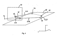
- Fig. 3 and 4 illustrated method performed according to a first preferred embodiment of the invention.
- Fig. 4 are, as in corresponding representations for further preferred embodiments of the invention also, individual steps indicated by dotted arrows, which are provided with the reference numerals of the corresponding steps.
- steps S10 and S12 a current depth-resolved image and a current video image are read in and preprocessed. These steps can be performed independently of each other in any order or even in parallel.
- step S10 if necessary after corrections of the data, a transformation of the position coordinates of the distance picture elements into a Cartesian vehicle coordinate system fixedly connected to the vehicle is carried out.
- the position coordinates which result from the polar coordinates in the scanning plane, by the Scanning plane, in which the object points corresponding to the distance pixels are located, supplemented certain position component to a complete position coordinate set in three dimensions.
- the location of a distance pixel the position defined by these coordinates will be referred to below.
- Each distance pixel is assigned an identifier, which is taken from a set of predetermined, currently unused identifiers.
- step S12 also after any corrections of the video image, the data of the video image is transformed into the vehicle coordinate system.
- a rectification of the video image data for example to eliminate distortions, and a transformation of the video pixels to an image plane used for defining or calculating an optical flow is performed (cf. Fig. 4 ).
- a modified pinhole model for the video camera 16 is used, which is defined by the position of an optical center 42 and the image plane 40. which serves as a surface for defining or determining the optical flow.
- the location of the optical center 42 is determined using the imaging geometry of the video camera 14.
- the pinhole camera model is modified for simplicity in that the image plane 40 is located at a fixed position between the optical center 42 and the object points, relative to the video system 14 on the vehicle 10, in FIG Fig. 4 the points 44 and 58, and by mirroring the actual image plane at the optical center 42 emerges from this.
- the current depth-resolved image and the current video image are then stored for further use.
- step S14 which is omitted in the first cycle, corresponding positions of respective video pixels in the image plane 40 are calculated using the camera model for all the range pixels from the cycle immediately preceding the current cycle, and stored for use in the following cycle. This is done geometrically in Fig. 4 for a previous cycle, the intersection 46 of a through a range pixel, in FIG Fig. 4 the distance pixel 44, and the optical center 42 extending straight line with the image plane 40 (see. Fig. 4 ).
- step S16 which is likewise omitted in the first cycle, corresponding actual optical flow vectors, hereinafter also referred to as optical flows, are then determined for all projected range image points or intersections of the preceding cycle on the basis of the video image from the immediately preceding cycle and from determined current cycle and converted by multiplication with the cycle time or the reciprocal of the sampling frequency in a shift.
- the optical flow vectors correspond to a speed of a shift of a corresponding intensity profile between two consecutive captures of video images.
- this is shown for the range pixel 44, for which at the intersection 46 an optical flux vector is determined which lies in the image plane 40 and which, after scaling with the cycle time, results in a displacement vector 48 beginning at the intersection 46.
- Optical flux vectors or the displacement vectors obtained by multiplication with the cycle time are generally indicated in the figures by arrows starting in a rhombus representing a video pixel or a projected location of a range pixel.
- the optical flow is determined by a differential method, in this example the " Performance of Optical Flow Techniques "by JL Barron, DJ Fleet, DJ and SS Beauchemin in International Journal of Computer Vision, 12 (1), pages 43-77 (1994) described by Lucas and Kanade.
- a predetermined value for the optical flow is stored for the corresponding distance pixel as a marker, which should not occur in reality.
- the optical flow corresponds to a speed here.
- it can also be determined as a corresponding shift over a cycle, so that the above-mentioned scaling can be omitted.
- Fig. 5 shows a scene with a motor vehicle 50 on a roadway 52 and a plurality of objects 53 on which, characterized by open circles, object points or distance pixels 54 have been detected. Characterized by arrows starting in a rhombus, or only by a rhombus are optical flow vectors 55 that could be calculated for corresponding range pixels, the arrow length corresponding to the magnitude of the displacement during one cycle.
- the optical flow can be determined in the example at the locations where the intensity has sufficiently strong spatial variations.
- step S18 which is likewise omitted in the first cycle, predicted distance image points are determined for all distance image points for which an optical flux could be determined, using the corresponding optical flows or the corresponding displacement vectors and the camera model, that is to say locations of corresponding object points predicted.
- Fig. 4 For the range pixel 44, geometrically illustrated, the intersection of a straight line through the optical center 42 and the end of the optical vector calculated displacement vector 48 with the scan plane 28 is determined to correspond to a predicted location 56 of the object pixel of the range pixel 44 Displays the distance pixel of the current cycle.
- step S20 which likewise is omitted in the first cycle, distance image points acquired for all predicted layers in the current cycle are searched, which are to be assigned to them according to a corresponding assignment criterion.
- the current range pixels 58 are searched that satisfy the assignment criteria such that their squared distance is less than a maximum squared distance, which is predetermined as a function of the resolution of the laser scanner 12 and the video system 14 and, if appropriate, other parameters ,
- a current range pixel When a current range pixel is assigned to a predicted slice or the corresponding range pixel from the previous cycle, it is given an identifier which in the previous cycle is assigned to the range pixel from the previous cycle had been.
- the previously assigned identifier is returned to the set of unused identifiers.
- Distance pixels with the same identifier therefore correspond to the substantially same object point, so that in this way there is a tracking of an object point for at least a few cycles. This object point corresponds to the identifier of the distance pixel. If multiple range pixels of the current cycle are to be assigned to the same range pixel of the previous cycle, only the identifier of that range pixel of the current cycle is replaced by that of the range pixel of the previous cycle closest to it.
- a segmentation of the current depth-resolved image is then performed.
- segments are formed, each of which comprises a single range pixel or a set of all range pixels, of which at least two corresponding to at least one segmentation criterion are defined as belonging to the segment, and which do not have any common range pixels.
- a segmentation criterion is used here that the square distance of the distance pixels is smaller than a predetermined, depending on the resolution of the laser scanner 12 selected, square separation distance.
- step S24 an assignment of segments to existing objects from a previous cycle then takes place.
- each object is assigned identifiers of range pixels which were contained in segments which were assigned to the object in a preceding cycle. Therefore, in the current cycle, each segment is assigned to those segments which have range pixels with an identifier assigned to the object in the previous cycle.
- By tracking the object points in the depth-resolved image it is thus possible to achieve that segments are only assigned to an object if the object point in question belongs to the object corresponding to the object.
- the assignment used in known algorithms alone over distance criteria can be improved or eliminated altogether.
- the object is now assigned all identifiers of those distance pixels which have occurred in segments which are assigned to the object.
- step S26 object properties such as the position of a center of gravity and, by comparison with the center of gravity in the previous cycle, then a speed of the center of gravity are determined from the locations of the range pixels and corresponding object data are output.
- the steps S12, S14, S18 and S20 by steps S28, S30, S32 and S34 replaced.
- the prediction and the assignment of distance pixels is not performed in the scan plane 28, but in the image plane 40 (see. Fig. 7 ).
- a device according to a second preferred embodiment of the invention is used for the implementation, in which, compared to the device according to the first preferred embodiment, the data processing device 18 is replaced by a data processing device programmed to carry out the method according to the second preferred embodiment.
- the same reference numerals are used for the sake of clarity, and the explanations for the first exemplary embodiment apply, unless otherwise stated, correspondingly.
- step S28 a roll and pitch angle compensation is performed as a correction in addition to the processing substeps in step S12.
- corresponding data are detected by means of a corresponding sensor system for rolling and pitch angle detection, which is already present in modern vehicles, and the positions of the video picture elements in the image plane 40 are correspondingly corrected.
- step S30 instead of the range pixels of the previous cycle, the range pixels of the current cycle are transferred to the image plane 40 and stored for use in step S16 in the next cycle.
- step S32 for each range pixel of the previous cycle, a predicted location in the image plane 40 given by the endpoint of the displacement vector 48 resulting from multiplication by the cycle time from the optical flow vector given by the intersection point 46 is determined into the image plane 40 projected range pixel of the previous cycle begins.
- Fig. 7 For example, the predicted location by a diamond and the current range pixel 58 projected into the image plane 40 are illustrated by a dotted circle 59.
- step S34 then, for each predicted location, among all distance pixels to be assigned in the image plane projected in the image plane in step S30, are searched.
- an assignment criterion it is used here that the quadratic distance of the predicted position in the image plane 40 and the position projected into the image plane 40 is smaller than a predetermined maximum square distance, which depends on the resolution capability of the laser scanner 12 and the video system 14 and maximum object speeds is given.
- the assignment of identifiers and distance pixels to one another takes place as in step S20.
- Steps S12 and S28 may also be interchanged in the methods of the first and second embodiments of the invention.
- the steps S18 and S20 are replaced by the steps S36 and S38 compared to the first embodiment.
- This method allows for an approximate treatment of errors that may be caused by pitching of the vehicle 10.
- a device according to a third preferred embodiment of the invention is used for the implementation, in which, compared to the device according to the first preferred embodiment, the data processing device 18 is replaced by a data processing device which is programmed to carry out the method according to the third preferred embodiment.
- the same reference numerals are used for the sake of clarity, and the explanations for the first exemplary embodiment apply, unless otherwise stated, correspondingly.
- FIG. 9 A corresponding situation is in Fig. 9 shown.
- a side surface of an object substantially orthogonal to the scanning plane 28 is shown in two immediately successive cycles, denoted by the reference numeral 60 in a position in a cycle immediately preceding the current cycle, and by the reference numeral 60 'in the current cycle .
- an object point 62 is detected on the side surface 60, which lies in the scanning plane 28 in this cycle.
- the same object point 62 is due to a pitching movement below the scanning plane 28 and thus is no longer accurately detectable.
- an object point 63 is detected which lies on both the side surface 60 'and in the scanning plane 28 and approximately orthogonal to the scanning plane 28 above the object point 62.
- this method does not predicate a single position for an object or distance pixel but rather a whole number of possible positions.
- step S36 for each distance pixel in the preceding cycle, for which an optical flux was determined, a beam running in the scanning plane with possible predicted positions of a corresponding object point is determined.
- a line outgoing from the end of the displacement vector which is given by multiplication of the optical flux corresponding to the distance image point with the cycle duration, may be at or near the distance image points of the current cycle to be assigned.
- the camera model is the modified pinhole camera model so that the straight line 64 passes through the optical center 42 and the end of the displacement vector 48 corresponding to the optical flow vector.
- This straight line 64 is now projected orthogonally onto the scanning plane 28, resulting in a straight line or a beam 66 starting at the projection of the point of intersection of the straight line 64 with the image plane 40 onto the scanning plane with predicted positions in the scanning plane.
- step S38 the assignment of distance pixels from the current cycle to each of the distance pixels of the instantaneous, preceding cycle in step S36 then takes place. It is now used as the assignment criterion for assignment to a current distance pixel 63 from the straight line 66 in the scanning plane 28 may have at most a predetermined maximum distance, which is similarly determined, as in the first embodiment.
- the straight line 66 is not determined, but used in the assignment of the distance of a current distance pixel 63 from the line 64 parallel to the scanning plane 28 instead of the distance from the straight line 66.
- the results are the same in each case, only differences in the execution speed can result.
- the method according to the third preferred embodiment is modified such that in the assignment the square distance from the straight line 64 is used, and not just the component parallel to the scanning plane 28. The determination of the straight line 66 is then not necessary.
- a device according to a fourth preferred embodiment of the invention is used for the implementation, in which, compared with the device according to the third preferred embodiment, the data processing device 18 is replaced by a data processing device programmed to carry out the method according to the fourth preferred embodiment.
- a method according to a fifth preferred embodiment of the invention differs from the method according to the third preferred embodiment in that two segmentation criteria are used.
- a second segmentation criterion it is now used that all distance pixels of a segment must have a speed which is different from those of the other range pixels in the segment by less than a predetermined speed limit.
- a corresponding speed is determined from the respective positions of the distance pixels in the current and the preceding cycle.
- the velocity is determined using the two range pixels closest to the curve.
- the point of intersection of the curve or straight line is determined with a straight line connecting the associated distance pixels.
- the speed is then calculated from the difference of the positions of the range pixel in the previous cycle and the point of intersection and dividing the difference by the cycle time. The speed thus determined is used for segmentation.
- a device for carrying out a device according to the fifth preferred embodiment of the invention is used, in which, compared to the device according to the third preferred embodiment, the data processing device is replaced by a data processing device, which is programmed to carry out the method according to the fifth preferred embodiment.
- steps S14, S36 and S38 are replaced by step S30 of the second embodiment as well as new steps S40 and S42 compared to the method according to the third preferred embodiment.
- the assignment now takes place in the image plane (cf. Fig. 10 and 11 ).
- a device according to a sixth preferred embodiment of the invention is used for the implementation, in which, compared to the device according to the third preferred embodiment, the data processing device 18 is replaced by a data processing device programmed to carry out the method according to the sixth preferred embodiment.
- the same reference numerals are used for the sake of clarity, and the explanations for the second or third exemplary embodiment apply, unless otherwise stated, correspondingly.
- Step S30 is performed as in the method according to the second preferred embodiment of the invention.
- step S40 for all distance pixels of the previous cycle for which an optical flow has been determined - Fig. 11 by way of example for the distance pixel 62 - in each case a straight line 68 (cf. Fig. 11 ) are determined with possible predicted layers of current distance image pixels projected into the image plane, which correspond to the same object point as the respectively considered distance image point of the preceding cycle.
- the straight line 68 extends orthogonal to the scanning plane 28 and in the image plane 40 through the end point of the through the corresponding optical flux vector determined displacement vector 48.
- step S42 it is then used as the assignment criterion that an assignment takes place only if the projected distance pixels determined in step S30, in Fig. 11 characterized by the dotted circle 70, from the straight line 68 in the image plane 40 have a square distance which is smaller than a predetermined maximum distance.
- Illustrated method according to a seventh preferred embodiment of the invention is a in Fig. 12 used in a side view device according to a seventh preferred embodiment of the invention.
- the laser scanner 12 is now replaced by a laser scanner 72, which, in Fig. 12 shown only schematically, four fan-like arranged scanning planes 74, 74 ', 74 "and 74"' has.
- a laser beam with an oblong rectangular profile is pivoted over the detection area and the light reflected from objects received by four appropriately aligned detectors, so that the result is a scan in four mutually inclined at a small angle scanning planes 74, 74 ', 74 " , 74 “'yields.
- the data processing device 18 is replaced by the data processing device 76, which differs from the data processing device 18 by the computer program, which is now set up for carrying out the method according to the seventh embodiment of the invention.
- the method differs from the method according to the second embodiment essentially in that, on the one hand, distance pixels are used in a plurality of scan planes and, on the other hand, as a consequence, step S32, i. the assignment of distance pixels is modified.
- FIG. 13 A situation similar to those in Fig. 9 and 11 corresponds, is exemplary in Fig. 13 shown.
- the same reference numerals are used.
- the distance pixels 78 "and 80" and the distance pixels 78 "'and 80"' are each located in a scanning plane.
- the processing of the range pixels and the video pixels is performed in all steps except the step S32 as in the method of the second preferred embodiment, but in the conversion, the angle of the respective scan plane to the video camera is taken into account.
- the in Fig. 13 Therefore, only the two detected distance pixels 80 "and 80"'are projected into the image plane 40 in accordance with their respective scan planes with a specific position in space and an optical flux and, if possible, a corresponding displacement vector are determined for this, which is shown in FIG Fig. 13 for clarity only for the range pixel 80 "'with the displacement vector 48.
- the four range pixels 78, 78', 78", 78 "'of the current cycle projecting into the image plane 40 taking into account the positions of the corresponding scanning planes. These correspond in Fig. 13 the points 81, 81 ', 81 "and 81"'.
- the assignment of distance image points of the current cycle to those of the previous cycle takes place in which an assignment is checked independently of the membership of a scanning plane.
- the assignment criterion is used such that an assignment takes place only if the quadratic distance of a distance pixel projected into the image plane 40 (in FIG Fig. 13 the points 81, 81 ', 81 "and 81"') of a predicated position (in Fig. 13 indicated by a diamond) is smaller than a predetermined square maximum distance.
- the range pixel 80 "'of the previous cycle which lies in the scan plane 74"' above the scan plane 74 ", is assigned the range pixel 78" of the current cycle in the scan plane 74 ".
- a method according to an eighth preferred embodiment of the invention differs from the method according to the seventh preferred embodiment in that in step S22 the segmentation is performed using two segmentation criteria which must be cumulatively satisfied.
- the segmentation criterion with respect to the distances does not differ from that in the other embodiments.
- the second segmentation criterion is now used that all the distance pixels of a segment must have a corresponding optical flux that differs from those of the other range pixels in the segment by less than a predetermined limit. This additional criterion makes segmentation much more selective.
- segments are tracked individually by tracking the identifiers of the distance pixels contained in them, so that a comparison of the positions of the segments, a rotation of the object to which the segments are assigned, is easily determined.
- a device according to an eighth preferred embodiment of the invention is used for the implementation, in which, compared to the device according to the seventh preferred embodiment, the data processing device 76 is replaced by a data processing device programmed to carry out the method according to the eighth preferred embodiment.
- the segmentation in the fifth or eighth embodiment can also be used correspondingly in the other exemplary embodiments, with distances of projected range pixels in the image plane being used, if appropriate, instead of the distances of distance pixels.
- a device is used according to a ninth preferred embodiment, which on the one hand instead of the laser scanner 12 a partially analogous to the laser scanner operating imaging Radar sensor which detects simultaneously with the distance or position data obtained by transit time measurement radial velocities, which are assigned to the distance pixels.
- the data processing device 18 is designed to carry out the method according to the ninth preferred embodiment of the invention by having a corresponding computer program according to the invention. For corresponding elements, therefore, the same reference numerals are used as in the first embodiment and the same statements apply accordingly.
- the method according to the ninth embodiment differs from the method according to the first embodiment, on the one hand, in that also the detected radial speeds must be transformed into the vehicle coordinate system, which takes place in a step corresponding to step S10.
- the prediction step S20 is modified.
- the underlying relationships are in Fig. 14 for the general case that a reference point 82 of the radar sensor does not coincide with the optical center 42 of the video camera 16.
- the image plane 40 remains unchanged.
- a straight line or a ray 88 can be formed in the xy plane, on or according to the prediction on the basis of the displacement given by the optical flow, the distance pixel of the current cycle must be.
- a radial displacement 92 is calculated based on the time interval between successive cycles and the optical flow.
- the predicted total displacement of the range pixel 44 of the previous cycle includes an orthogonal tangential displacement in addition to this radial component.
- the radar sensor Since the radar sensor detects relatively large or high object areas due to the vertical extent of the radar lobe, it may be necessary in a modified method by using contextual knowledge to hide the background and possibly parts of the foreground, for example the roadway.
- the respective ones can also be used be corrected from this derivable displacement vectors.
- a weighted average is formed from the common components of the radial velocity and the optical flow vector or the corresponding displacements, for example in accordance with the measurement accuracy.
- the remaining component of the optical flux vector or the corresponding displacement is then multiplied by the ratio of the size of the component in the direction of the radial velocity and the averaged value, so that a corrected displacement vector results from the mean value and the rescaled remaining component. In this way, the quality of the prediction can be further increased.
- the calculation of the optical flow is performed with a pyramidal implementation of the differential method.
- the image is first reduced in size and measured in this reduced image of the optical flow. This is propagated into the next larger picture and refined. These steps are repeated until the image is returned to its original size.
- the optical flows are determined by means of a correlation method.
- the apparatus comprises a video camera by means of which video images can be detected at a frequency twice the frequency for detecting the depth-resolved images. There are then read in each cycle at approximately the same time intervals two video images. Because the optical flow is always calculated for range pixels in the previous cycle, the optical flux for the first half of the cycle can thus already be determined parallel to reading in the current depth-resolved image, while the optical flow for the second half is calculated at the same time as before. The total displacement is then obtained by adding the two optical flow vectors and multiplying by half the cycle time. In this way, an increased accuracy in the determination of the optical flow is achieved.
- Fig. 15 is a section of a depth-resolved image shown in which, each marked by dotted rectangles, two passenger cars 98 and 100 in the y-direction moving bus 102 partially obscure.
- the bus 102 also appears in successive images only as a rectilinear segment 103 which does not change its position.
- the moving bus could therefore be assigned only zero speed in the y-direction with a conventional object tracking method.
- a lateral velocity component can be calculated using the optical flow for individual distance pixels on the bus contour. This is especially important when the bus seems to disappear by occlusion.
- bus 102 features on the article, i. the bus 102, which are located not only in the scanning plane, but also above or below this, if the optical flow is accordingly extrapolated or interpolierbar.
- Fig. 16a and 16b is shown as a section of a distance image, a situation in which initially two indicated by dotted lines vehicles 104 and 106 park closely adjacent to the viewing direction and then the rear vehicle 106 ausparkt and thereby moves transversely to the viewing direction. As in Fig. 16a and 16b As shown, this situation would be evaluated with object tracking based solely on depth-resolved images such that only an object contour of a single object indicated by a dashed line is moved.
- the segment corresponding to the vehicle 106 contains only range pixels that have a different optical flux than the range pixels of the segment corresponding to the vehicle 106. Therefore, both segments would not be assigned to the same object.
- a pedestrian enters the street between the parked vehicles.
- the pedestrian can usually only be separated from the parked vehicles when he has moved away from the background, ie the parked vehicles in a lateral or longitudinal direction. In practice, this means that the pedestrian is often already on the street before it can be safely recognized as such by object tracking such an object.
- the optical flow is additionally calculated and used to process the distance image points, then the pedestrian can be recognized as a self-moving object at an early stage, even if he is still partially covered by a vehicle.
- optical flow in the region of the pedestrian is, due to the arm and leg movement, highly inhomogeneous and thus differs significantly from its environment or its background. This inhomogeneity can be detected and used for the classification and / or recognition of an object. For example, when a strongly inhomogeneous optical flow occurs, a pedestrian's hypothesis can be established for an object corresponding to the pedestrian.
- a pedestrian who moves directly in front of a wall or a vehicle for example, when the pedestrian pushes along the wall or presses against the vehicle, can often not be distinguished from the background in an object tracking only on the basis of distance pixels. Considering the optical flow, however, this is possible, as just described.
Landscapes
- Engineering & Computer Science (AREA)
- Physics & Mathematics (AREA)
- Remote Sensing (AREA)
- Radar, Positioning & Navigation (AREA)
- General Physics & Mathematics (AREA)
- Computer Networks & Wireless Communication (AREA)
- Electromagnetism (AREA)
- Multimedia (AREA)
- Theoretical Computer Science (AREA)
- Length Measuring Devices By Optical Means (AREA)
- Image Analysis (AREA)
- Measurement Of Optical Distance (AREA)
- Optical Radar Systems And Details Thereof (AREA)
Abstract
Description
Die vorliegende Erfindung betrifft ein Verfahren zur Verarbeitung von zyklisch erfassten, tiefenaufgelösten Bildern und Videobildern eines gemeinsamen Erfassungsbereichs sowie eine Vorrichtung zur Überwachung eines Überwachungsbereichs. Ein derartiges Verfahren bzw. eine derartige Vorrichtung mit den Merkmalen des Oberbegriffs des Anspruchs 1 bzw. 31 ist aus
Zur Überwachung von Überwachungsbereichen, insbesondere vor Fahrzeugen, können Sensoren für elektromagnetische Strahlung, beispielsweise Laserscanner, eingesetzt werden, mittels derer im Folgenden als "tiefenaufgelöst" bezeichnete Bilder eines den Überwachungsbereich umfassenden Erfassungsbereichs erfassbar sind. Diese tiefenaufgelösten Bilder umfassen wenigstens einen, in der Regel aber mehrere Entfernungsbildpunkte, die die Lage eines von dem Sensor erfassten Gegenstandspunktes auf einem Gegenstand in wenigstens einer Abtastebene des Sensors wiedergeben. Insbesondere enthalten die Entfernungsbildpunkte Daten, mittels derer der Abstand des Gegenstandspunkts von dem Sensor und ein auf eine vorgegebene Achse des Sensors bezogener Winkel, unter dem der Gegenstandspunkt erfasst wurde, ermittelbar ist.For monitoring monitoring areas, in particular in front of vehicles, it is possible to use sensors for electromagnetic radiation, for example laser scanners, by means of which images of a detection area encompassing the monitoring area can be detected below as "depth-resolved". These depth-resolved images comprise at least one, but usually a plurality of distance pixels, which reproduce the position of an object point detected by the sensor on an object in at least one scanning plane of the sensor. In particular, the distance pixels contain data by means of which the distance of the object point from the sensor and an angle related to a predetermined axis of the sensor, under which the object point was detected, can be determined.
Der Überwachungsbereich wird dann überwacht, indem tiefenaufgelöste Bilder erfasst werden und auf der Basis der erfassten tiefenaufgelösten Bilder eine Objektverfolgung durchgeführt wird. Idealerweise entspricht dabei ein Objekt einem erfassten Gegenstand.The surveillance area is then monitored by capturing depth-resolved images and object tracking based on the acquired depth-resolved images. Ideally, an object corresponds to a detected object.
Zur Verfolgung der Objekte werden die tiefenaufgelösten Bilder segmentiert, indem Mengen von Entfernungsbildpunkten gebildet werden, die entsprechend einem Segmentierungskriterium als benachbart angesehen werden. Die in jedem Zyklus gebildeten Segmente werden dann Objekten in dem vorhergehenden Zyklus zugeordnet und aus den zugeordneten Segmenten bzw. deren Entfernungsbildpunkten werden neue Lagen der Objekte bestimmt.To track the objects, the depth-resolved images are segmented by forming sets of range pixels that are considered adjacent according to a segmentation criterion. The segments formed in each cycle are then assigned to objects in the previous cycle, and new locations of the objects are determined from the associated segments or their distance pixels.
Zur besseren Verfolgung der Objekte werden die Segmente dabei nicht den Objekten des vorhergehenden Zyklus direkt zugeordnet, sondern es werden Lagen der Objekte in dem aktuellen Zyklus prädiziert, auf deren Basis die Segment-Objekt-Zuordnung erfolgen kann.In order to better track the objects, the segments are not directly assigned to the objects of the previous cycle, but positions of the objects in the current cycle are predicted, on the basis of which the segment-object assignment can take place.
In Situationen mit vielen Gegenständen, beispielsweise im Innenstadtverkehr, treten häufig Situationen auf, in denen Gegenstände teilweise oder auch ganz für kurze Zeit verdeckt werden. Weiterhin kann sich durch eine schnelle Drehung eines Gegenstands dessen Kontur in dem tiefenaufgelösten Bild verändern. Dies kann dazu führen, dass für einen Gegenstand unterschiedliche Anzahlen von Entfernungsbildpunkten erfasst werden, die unter Umständen zu Segmenten zusammengefasst werden, deren Anzahl sich von der im vorhergehenden Zyklus unterscheidet. Dies kann die Segment-Objekt-Zuordnung wesentlich erschweren. Weiterhin kann sich das Erscheinungsbild von ruhenden Gegenständen durch die Eigenbewegung des Fahrzeugs ändern. Dies ist insbesondere dann problematisch, wenn diese, wie zum Beispiel Büsche am Fahrbahnrand, eine unregelmäßige Kontur aufweisen, die die Wiedererkennung eines entsprechenden Objekts erschwert.In situations with many objects, for example in inner city traffic, situations often arise in which objects are partially or completely concealed for a short time. Furthermore, a fast rotation of an object can change its contour in the depth-resolved image. This may result in different numbers of range pixels being detected for an item, which may be grouped into segments the number of which differs from that in the previous cycle. This can make segment-object mapping much more difficult. Furthermore, the appearance of dormant objects may change due to the intrinsic motion of the vehicle. This is particularly problematic if they, such as bushes on the roadside, have an irregular contour, which makes the recognition of a corresponding object more difficult.
Die Veröffentlichung von
Der vorliegenden Erfindung liegt daher die Aufgabe zugrunde, ein Verfahren bereitzustellen, das eine gute Verarbeitung tiefenaufgelöster Bilder eines Überwachungsbereichs auch in Situationen mit mehr als einem Gegenstand in dem Überwachungsbereich erlaubt, sowie eine Vorrichtung zu schaffen, mittels derer das Verfahren durchführbar ist.It is therefore an object of the present invention to provide a method which allows good processing of depth-resolved images of a surveillance area even in situations with more than one object in the surveillance area, as well as to provide a device by means of which the method is feasible.
Die Aufgabe wird gelöst durch ein Verfahren mit den Merkmalen des Anspruchs 1.The object is achieved by a method having the features of claim 1.
Bei dem erfindungsgemäßen Verfahren zur Verarbeitung von zyklisch erfassten, tiefenaufgelösten Bildern und Videobildern eines gemeinsamen Erfassungsbereichs, die jeweils Gegenstandspunkten auf wenigstens einem Gegenstand in dem Erfassungsbereich entsprechende Entfernungsbildpunkte bzw. Videobildpunkte umfassen, wird in aufeinander folgenden Zyklen für jeweils wenigstens einen Entfernungsbildpunkt für einen dem Entfernungsbildpunkt entsprechenden Gegenstandspunkt ein optischer Fluss ermittelt.In the method according to the invention for processing cyclically acquired, depth-resolved images and video images of a common detection area, which respectively comprise object points on at least one object in the detection area corresponding pixels or pixels, is in successive cycles for each at least one distance pixel corresponding to the distance pixel Object point an optical flux determined.
Die Aufgabe wird weiterhin gelöst durch eine Vorrichtung mit den Merkmalen des Anspruchs 31.The object is further achieved by a device having the features of
Das erfindungsgemäße Verfahren ist zusammen mit einer Erfassung der tiefenaufgelösten Bilder und der Videobilder mittels der erfindungsgemäßen Vorrichtung durchführbar.The method according to the invention can be carried out together with a detection of the depth-resolved images and the video images by means of the device according to the invention.
Die erfindungsgemäße Vorrichtung zur Überwachung eines Überwachungsbereichs umfasst einen Sensor für elektromagnetische Strahlung, mittels dessen in zeitlicher Folge tiefenaufgelöste Bilder eines ersten Erfassungsbereichs erfassbar sind, ein Videosystem, mittels dessen in einer auf die Erfassungszeiten der tiefenaufgelösten Bilder abgestimmten zeitlichen Folge Videobilder eines zweiten Erfassungsbereichs, der sich wenigstens teilweise mit dem ersten Erfassungsbereich in dem Überwachungsbereich überschneidet, erfassbar sind, eine erste Einrichtung zur Verarbeitung von mit dem Sensor für elektromagnetische Strahlung erfassten tiefenaufgelösten Bildern, und eine zweite Einrichtung zur Ermittlung eines optischen Flusses für wenigstens Teilbereiche der Videobilder, die durch Daten bestimmbar sind, die aus den tiefenaufgelösten Bildern mit Hilfe der ersten Einrichtung zur Verarbeitung tiefenaufgelöster Bilder ermittelbar sind.The device according to the invention for monitoring a monitoring area comprises a sensor for electromagnetic radiation, by means of which images of a first detection area, which are resolved in depth in time, are displayed a video system, by means of which in a time sequence adapted to the acquisition times of the depth-resolved images, video images of a second detection area which at least partially overlaps the first detection area in the surveillance area can be detected, a first device for processing with the sensor for electromagnetic radiation detected depth-resolved images, and second means for determining an optical flow for at least portions of the video images, which are determinable by data, which can be determined from the depth-resolved images using the first means for processing depth-resolved images.
Ein Aspekt der vorliegenden Erfindung besteht darin, die Informationen aus den tiefenaufgelösten Bildern mit Informationen aus entsprechenden Videobildern zu verknüpfen und so zu wenigstens einem Entfernungsbildpunkt zusätzliche Daten zu erhalten, die bei der Verarbeitung der Entfernungsbildpunkte verwendet werden können. Insbesondere wird ausgenutzt, dass bei einer Bewegung eines Gegenstands in der Regel in dem tiefenaufgelösten Bild und dem Videobild erfasste Bereiche auf dem Gegenstand mitbewegt werden. Weisen die Bereiche in dem Videobild einen Intensitätsverlauf bzw. entsprechende Merkmale auf, äußert sich die Bewegung des Gegenstands näherungsweise als Verschiebung der entsprechenden Intensitätsverläufe bzw. Merkmale in dem Videobild. Diese Verschiebung bzw. die Geschwindigkeit der Verschiebung ist aber über den optischen Fluss ermittelbar. Diese Bewegungsinformation aus den Videobildern kann dann den entsprechenden Bereichen des Gegenstands bzw. entsprechenden Entfernungsbildpunkten zugeordnet werden.One aspect of the present invention is to combine the information from the depth-resolved images with information from corresponding video images and thus to obtain at least one range pixel additional data that can be used in the processing of the range pixels. In particular, use is made of the fact that, in the case of a movement of an object, regions detected in the depth-resolved image and the video image are usually moved on the object. If the areas in the video image have an intensity profile or corresponding features, the movement of the object manifests itself approximately as a displacement of the corresponding intensity profiles or features in the video image. However, this shift or the speed of the shift can be determined via the optical flow. This motion information from the video images can then be assigned to the corresponding areas of the object or to corresponding distance picture elements.
Das erfindungsgemäße Verfahren geht daher aus von zyklisch erfassten tiefenaufgelösten Bildern und Videobildern eines gemeinsamen Erfassungsbereichs.The method according to the invention is therefore based on cyclically acquired, depth-resolved images and video images of a common detection area.
Tiefenaufgelöste Bilder umfassen dabei wenigstens einen, in der Regel mehrere Entfernungsbildpunkte, die Daten in Bezug auf die Lage und insbesondere die Entfernung entsprechender erfasster Gegenstandspunkte auf einem Gegenstand von einem zur Erfassung verwendeten Sensor enthalten. Da Sensoren zur Erfassung solcher tiefenaufgelöster Bilder in der Regel keine Punkte im mathematischen Sinne auflösen können, wird dabei unter einem Gegenstandspunkt ein Bereich auf der Oberfläche eines Gegenstands verstanden, der von dem entsprechenden Sensor räumlich auflösbar ist. Zur einfachen und intuitiven Formulierung wird im Folgenden von der Lage von Entfernungsbildpunkten gesprochen, um die durch die Daten in Bezug auf die Lage der Gegenstandspunkte definierten Positionen zu benennen.In this case, depth-resolved images comprise at least one, as a rule a plurality of distance pixels, which contain data relating to the position and in particular the distance of corresponding detected object points on an object from a sensor used for the detection. Since sensors for detecting such depth-resolved images usually can not resolve points in the mathematical sense, an object point means an area on the surface of an object which can be spatially resolved by the corresponding sensor. For the sake of simplicity and intuition, the position of distance pixels will be referred to below in order to identify the positions defined by the data relating to the location of the object points.
Bei der erfindungsgemäßen Vorrichtung ist zur Erfassung der tiefenaufgelösten Bilder des ersten Erfassungsbereichs wenigstens ein Sensor für elektromagnetische Strahlung vorgesehen, bei dem es sich grundsätzlich um einen beliebigen Sensor für elektromagnetische Strahlung handeln kann, mittels dessen die tiefenaufgelösten Bilder, vorzugsweise ohne Verwendung eines optischen Flusses, erfassbar sind. Beispielsweise kann ein Stereovideokamerasystem mit zwei Videokameras verwendet werden, die in einer Ebene, in der eine Entfernung von dem Stereovideokamerasystem erfasst wird, beabstandet angeordnet sind. Vorzugsweise werden jedoch Sensoren verwendet, bei denen wenigstens ein Abtaststrahl mit elektromagnetischer Strahlung zur Abtastung wenigstens einer Abtastebene verwendet wird. Dabei können mehrere Abtaststrahlen zur im Wesentlichen gleichzeitigen Abtastung einer jeweiligen Abtastebene verwendet werden oder es kann, vorzugsweise, ein Abtaststrahl in der Abtastebene geschwenkt werden, wobei jeweils von Gegenständen zurückgeworfene Strahlung mit einem entsprechenden Detektor empfangen wird.In the device according to the invention, at least one sensor for electromagnetic radiation is provided for detecting the depth-resolved images of the first detection area, which can basically be any sensor for electromagnetic radiation, by means of which the depth-resolved images, preferably without the use of an optical flow, can be detected are. For example, a stereo video camera system may be used with two video cameras spaced in a plane in which a distance is detected by the stereo video camera system. Preferably, however, sensors are used in which at least one scanning beam with electromagnetic radiation for scanning at least one scanning plane is used. In this case, a plurality of scanning beams can be used for essentially simultaneous scanning of a respective scanning plane or, preferably, a scanning beam can be pivoted in the scanning plane, wherein radiation reflected from objects is received by a corresponding detector.
Die bei dem erfindungsgemäßen Verfahren verwendeten Videobilder umfassen Videobildpunkte, die wenigstens Daten in Bezug auf Intensitätswerte erfasster Gegenstandsbereiche als Funktion einer Lage auf einer Empfangsfläche umfassen, auf der entsprechende optische Strahlung empfangen wird. Entsprechend einer Abbildungsgeometrie des zur Erfassung verwendeten Videosystems und gegebenenfalls einer Weiterverarbeitung der erfassten Daten ergeben sich aus den Positionen von erfassten Gegenstandsbereichen die Lagen, an denen in dem Videobild Intensitätswerte gegeben sind. Die Lagen können insbesondere in einer Ebene angegeben sein.The video images used in the method of the invention include video pixels that include at least data related to intensity values of detected subject areas as a function of a location on a receiving surface upon which corresponding optical radiation is received. Corresponding to an imaging geometry of the video system used for the detection and, if appropriate, a further processing of the acquired data, the positions at which the video image contains intensity values result from the positions of detected object regions. The layers can be specified in particular in one plane.
Es können grundsätzlich auch Farbvideobilder verwendet werden, bei denen die Videobildpunkte Daten in Bezug auf Intensitätswerte für wenigstens zwei Farben aufweisen.In principle, color video images may also be used in which the video pixels have data related to intensity values for at least two colors.
Die erfindungsgemäße Vorrichtung weist zur Erfassung von Videobildern ein Videosystem auf, das wenigstens eine Videokamera umfassen kann, die eine abbildende Optik und ein Sensorsystem zum ortsaufgelösten Empfang von optischer Strahlung, beispielsweise von sichtbarem Licht oder infraroter Strahlung, aufweist. Als Videokamera kann je nach Anwendung insbesondere eine Weitwinkel- oder eine Panoramakamera zum Einsatz kommen. Zur Überwachung des Fernbereichs ist eine Videokamera mit einem Teleobjektiv besonders geeignet. Es können grundsätzlich auch Videokameras mit Zoom-Objektiven verwendet werden. Weiterhin kann als Sensorsystem ein Schwarz-Weiß- bzw. Graustufensystem oder auch ein farbempfindliches System zum Einsatz kommen. Dabei können beispielsweise entsprechende CCD- oder CMOS- Sensorelemente verwendet werden.The device according to the invention has a video system for capturing video images, which may comprise at least one video camera which has an imaging optics and a sensor system for the spatially resolved reception of optical radiation, for example visible light or infrared radiation. Depending on the application, in particular a wide-angle camera or a panoramic camera can be used as the video camera. To monitor the long range is a video camera especially suitable with a telephoto lens. In principle, video cameras with zoom lenses can also be used. Furthermore, a black-and-white or grayscale system or even a color-sensitive system can be used as the sensor system. In this case, for example, corresponding CCD or CMOS sensor elements can be used.
Die Erfassungsbereiche des Sensors für elektromagnetische Strahlung und des Videosystems brauchen dabei nicht identisch zu sein, es genügt, dass diese sich im Überwachungsbereich überschneiden.The detection ranges of the sensor for electromagnetic radiation and the video system need not be identical, it is sufficient that these overlap in the surveillance area.
Für wenigstens einen gegebenen Entfernungsbildpunkt wird bei dem erfindungsgemäßen Verfahren ein optischer Fluss auf der Basis von wenigstens zwei in zeitlichem Abstand erfassten Videobildern ermittelt. Unter dem optischen Fluss wird erfindungsgemäß ein wenigstens näherungsweises Abbild von Geschwindigkeiten von Gegenstandspunkten oder von Verschiebungen von Gegenstandspunkten innerhalb eines vorgegebenen Zeitintervalls in drei Dimensionen auf einer zur Definition des optischen Flusses verwendeten Fläche verstanden. Im Rahmen der Erfindung sind beide Definitionen, d.h. die über Geschwindigkeiten und die über Verschiebungen gleichwertig, da sich die Werte durch Skalierung mit dem entsprechenden Zeitintervall ineinander überführen lassen. Werden zur Ermittlung des optischen Flusses nur zwei Videobilder verwendet, unterscheiden sich die optischen Flüsse, die über eine Geschwindigkeit und über eine Verschiebung ermittelt werden nur durch einen Skalierungsfaktor, der im Wesentlichen durch die Dauer des Zeitintervalls gegeben ist. Der optische Fluss ist daher genauer durch einen zweidimensionalen Vektor in der zur Definition des optischen Flusses verwendeten Fläche angebbar, wobei jedoch im Folgenden der Einfachheit halber meist nur der Begriff "optischer Fluss" verwendet wird. Die Videobilder können grundsätzlich einen beliebigen zeitlichen Abstand aufweisen, doch ist bei Verwendung von nur zwei Videobildern der Abstand vorzugsweise nicht größer als der Zeitabstand, in dem tiefenaufgelöste Bilder erfasst werden.For at least one given range pixel in the method according to the invention, an optical flow is determined on the basis of at least two video images acquired at a time interval. According to the invention, the optical flow is understood as meaning an at least approximate image of speeds of object points or displacements of object points within a given time interval in three dimensions on an area used for defining the optical flow. In the context of the invention, both definitions, ie those relating to speeds and those over shifts, are equivalent, since the values can be converted into one another by scaling with the corresponding time interval. If only two video images are used to determine the optical flow, the optical flows, which are determined via a speed and a displacement, differ only by a scaling factor, which is essentially given by the duration of the time interval. The optical flow is therefore more accurate by a two-dimensional vector in the area used to define the optical flow can be specified, but in the following, for the sake of simplicity, usually only the term "optical flow" is used. The video images may in principle have an arbitrary time interval, but when using only two video images, the distance is preferably not greater than the time interval in which depth-resolved images are acquired.
Im Rahmen der Erfindung wird dabei darunter, dass Verarbeitungsschritte in aufeinanderfolgenden Zyklen durchgeführt werden, verstanden, dass die Zyklen zeitlich gegeneinander versetzt sind. Sie brauchen jedoch nicht unbedingt unmittelbar aufeinander zu folgen, obwohl dies bevorzugt ist.In the context of the invention, it is understood here that processing steps are carried out in successive cycles, that the cycles are offset in time from one another. However, they do not necessarily follow one another directly, although this is preferred.
Im Folgenden wird im Zusammenhang mit dem optischen Fluss bzw. einer aus dem optischen Fluss bestimmten Geschwindigkeit häufig von einer der Geschwindigkeit entsprechenden Verschiebungen gesprochen. Damit ist dann eine Verschiebung gemeint, die sich durch Multiplikation eines vorgegebenen Zeitintervalls mit der dem optischen Fluss entsprechenden Geschwindigkeit ergibt. Bei dem Zeitintervall kann es sich dabei insbesondere um den zeitlichen Abstand zwischen zwei Zyklen handeln.In the following, in connection with the optical flow or a speed determined by the optical flow, one frequently speaks of a displacement corresponding to the speed. This then means a shift resulting from multiplication of a given time interval with the speed corresponding to the optical flow. The time interval may in particular be the time interval between two cycles.
Bei der zur Definition des optischen Flusses verwendeten Fläche kann zum einen eine Bildebene verwendet werden, in der die Videobildpunkte des dann ebenfalls in der Ebene definierten Videobildes liegen. Vorzugsweise wird jedoch eine Fläche verwendet, die im Rahmen eines Kameramodells zur Behandlung des Videobildes verwendet wird.In the area used to define the optical flow, on the one hand, an image plane can be used in which the video pixels of the video image then defined in the plane lie. Preferably, however, an area is used which is used in the context of a camera model for the treatment of the video image.
Erfindungsgemäß genügt es, wenn für wenigstens einen Entfernungsbildpunkt ein optischer Fluss ermittelbar ist. Im Allgemeinen kann nämlich der Fall auftreten, dass Entfernungsbildpunkte auf Gegenstandsflächen erfasst werden, die keine Intensitätsstruktur aufweisen und für die daher auch ein optischer Fluss nicht ermittelbar ist. Der optische Fluss ist beispielsweise dann vollständig ermittelbar, wenn der entsprechende Bereich des Videobildes in zwei linear von einander unabhängigen Richtungen eine Änderung der Intensität aufweist. Vorzugsweise wird das erfindungsgemäße Verfahren daher auf diese Bereiche angewendet.According to the invention, it is sufficient if an optical flux can be determined for at least one distance pixel. In fact, in general, the case may occur that range pixels on subject areas are detected, which have no intensity structure and for which therefore an optical flux can not be determined. The optical flow can be completely determined, for example, if the corresponding region of the video image has a change in the intensity in two linearly independent directions. Preferably, the method according to the invention is therefore applied to these areas.
Verfahren zur Berechnung des optischen Flusses sind grundsätzlich bekannt und beispielsweise in dem Artikel "
Der optische Fluss braucht dabei nicht unbedingt für das ganze Videobild berechnet zu werden. Es genügt vielmehr, diesen für den dem Entfernungsbildpunkt entsprechenden Gegenstandspunkt bzw. - soweit notwendig - dessen Umgebung zu ermitteln. Der Ort in der zur Definition des optischen Flusses verwendeten Fläche, für den der optische Fluss berechnet werden muss, ist aus den Lagekoordinaten des Entfernungsbildpunktes, der Relativlage des zur Erfassung der tiefenaufgelösten Bilder verwendeten Sensors zu dem zur Erfassung der Videobilder verwendeten Videosystem, der Abbildungsgeometrie des Videosystems bzw. einer Videokamera darin bzw. eines Modells für diese und der vorgegebenen Fläche auf der der optische Fluss ermittelt werden soll, ableitbar. Dabei kann als Ort ein entsprechender Videobildpunkt verwendet werden, es ist jedoch auch möglich, den optischen Fluss subpixelgenau an Orten zwischen Videobildpunkten bzw. Pixeln des Videobildes zu ermitteln. Weiterhin kann es genügen, dass der optische Fluss nur in der Nachbarschaft eines einem Entfernungsbildpunkt entsprechenden Ortes in dem Videobild ermittelbar ist, wenn der optische Fluss aufgrund von Stetigkeits- und/oder Glattheitseigenschaften eine Extrapolation oder Interpolation auf diesen Ort zulässt.The optical flow does not necessarily have to be calculated for the entire video image. Rather, it is sufficient to determine this for the distance point corresponding object point or - if necessary - its environment. The location in the area used to define the optical flow for which the optical flux must be calculated is from the positional coordinates of the range pixel, the relative position of the sensor used to acquire the depth resolved images to the video system used to capture the video images, the imaging geometry of the Video system or a video camera therein or a model for this and the predetermined surface on which the optical flow is to be determined derivable. It can be used as a place a corresponding video pixel, but it is also possible to determine the optical flow subpixel accurately at locations between video pixels or pixels of the video image. Furthermore, it may suffice that the optical flux can only be determined in the vicinity of a location corresponding to a distance pixel in the video image if the optical flux permits extrapolation or interpolation to this location due to continuity and / or smoothness properties.
Bei dem Konzept des optischen Flusses wird davon ausgegangen, dass der optische Fluss die Verschiebung von Intensitätsverläufen und damit von Merkmalen in einem Videobild und somit von den Merkmalen entsprechenden Gegenstandsbereichen wiedergibt. Durch die Verwendung des optischen Flusses können daher für einen gegebenen Entfernungsbildpunkt zusätzlich Informationen in Bezug auf Geschwindigkeiten bzw. den Geschwindigkeiten entsprechende Verschiebungen des dem Entfernungsbildpunkt entsprechenden Gegenstandspunktes wenigstens näherungsweise erhalten werden.In the concept of optical flow, it is assumed that the optical flow reflects the displacement of intensity gradients and thus of features in a video image and thus object areas corresponding to the features. Therefore, by using the optical flow, in addition, for a given range pixel, information relating to velocities or displacements corresponding to the velocities of the object point corresponding to the range pixel can be at least approximately obtained.
Diese zusätzliche Information kann dazu verwendet werden, einem vorgegebenen Gegenstandspunkt entsprechenden Entfernungsbildpunkte über mehrere Zyklen zu ermitteln und so zu verfolgen. Dies erlaubt es, Entfernungsbildpunkte auch in Situationen mit mehreren Objekten bzw. Gegenständen mit größerer Sicherheit Objekten zuzuordnen, was die Objektverfolgung erleichtert. Dabei ist es nicht notwendig, dass ein optischer Fluss für alle Entfernungsbildpunkte ermittelbar ist.This additional information can be used to determine a predetermined object point corresponding distance pixels over several cycles and to track it. This makes it possible to assign distance pixels to objects with greater security even in situations with multiple objects, which facilitates object tracking. It is not necessary that an optical flux for all distance pixels can be determined.
Die aus dem optischen Fluss ermittelten Daten können zur Weiterverarbeitung gespeichert oder ausgegeben werden.The data obtained from the optical flow can be stored or output for further processing.
Zur Verarbeitung der Entfernungsbildpunkte ist bei der erfindungsgemäßen Vorrichtung die erste Einrichtung vorgesehen, die insbesondere einen entsprechend programmierten Prozessor, beispielsweise eine digitalen Signalprozessor (DSP), einen mit diesem verbundene Speicher sowie Schnittstellen zu dem Sensor für elektromagnetische Strahlung aufweisen kann.For processing the distance pixels, the device according to the invention provides the first device, which in particular can have a correspondingly programmed processor, for example a digital signal processor (DSP), a memory connected thereto and interfaces to the sensor for electromagnetic radiation.
Zur Ermittlung des optischen Flusses ist bei der erfindungsgemäßen Vorrichtung die zweite Einrichtung vorgesehen, die einen entsprechend programmierten Prozessor, beispielsweise einen digitalen Signalprozessor, sowie einen mit diesem verbundenen Speicher aufweisen kann.To determine the optical flow, the second device is provided in the device according to the invention, which may have a correspondingly programmed processor, such as a digital signal processor, and a memory connected thereto.
Zur Zusammenführung der Daten sind die erste und die zweite Einrichtung miteinander verbunden.To merge the data, the first and second devices are interconnected.
Grundsätzlich können die erste und die zweite Einrichtung auch nur über einen gemeinsamen Prozessor verfügen, der dann entsprechend programmiert und über Schnittstellen mit dem Sensor zur Erfassung elektromagnetischer Strahlung und dem Videosystem verbunden sein kann.In principle, the first and the second device can also have only one common processor, which can then be correspondingly programmed and connected via interfaces to the sensor for detecting electromagnetic radiation and the video system.
Die erfindungsgemäße Vorrichtung erlaubt, da sie zur Durchführung des erfindungsgemäßen Verfahrens verwendbar ist, eine besonders gute Überwachung des Überwachungsbereichs.The device according to the invention, since it can be used to carry out the method according to the invention, allows a particularly good monitoring of the monitored area.
Weiterbildungen und bevorzugte Ausführungsformen der Erfindung sind in den Ansprüchen, der Beschreibung und den Zeichnungen beschrieben.Further developments and preferred embodiments of the invention are described in the claims, the description and the drawings.
Bevorzugt sind die Einrichtungen zur Ermittlung des optischen Flusses und zur Verarbeitung der tiefenaufgelösten Bilder zur Durchführung des erfindungsgemäßen Verfahrens ausgebildet.The devices for determining the optical flow and for processing the depth-resolved images are preferably designed to carry out the method according to the invention.
Grundsätzlich können zur Erfassung der tiefenaufgelösten Bilder beliebige Sensoren zur Erfassung elektromagnetischer Strahlung verwendet werden. Es ist jedoch bei der erfindungsgemäßen Vorrichtung bevorzugt, dass der Sensor für elektromagnetische Strahlung einen Laserscanner umfasst. Dabei kann es sich besonders bevorzugt um einen Laserscanner handeln, mittels dessen ein gepulster Laserstrahl im Bereich optischer Frequenzen, insbesondere im infraroten oder sichtbaren Bereich, über einen Erfassungsbereich schwenkbar ist und von Gegenstandspunkten zurückgeworfene Strahlungspulse detektierbar und durch Messung der Laufzeit der Strahlungspulse Entfernungen der jeweiligen Gegenstandspunkte ermittelbar sind. Solche Sensoren zeichnen sich durch eine hohe Messgenauigkeit und Auflösung auf.In principle, any sensors for detecting electromagnetic radiation can be used to acquire the depth-resolved images. However, it is preferred in the device according to the invention that the sensor for electromagnetic radiation comprises a laser scanner. This may be particularly preferably a laser scanner, by means of which a pulsed laser beam in the range of optical frequencies, in particular in the infrared or visible range, is pivotable over a detection range and reflected from object points radiation pulses detectable and by measuring the duration of the radiation pulses distances of the respective object points can be determined. Such sensors are characterized by a high measurement accuracy and resolution.
Nach einer anderen Ausführungsform ist es bevorzugt, dass der Sensor für elektromagnetische Strahlung einen, insbesondere Bild gebenden, Radarsensor umfasst. Bei diesem Radarsensor kann es sich insbesondere um einen Radarsensor handeln, mittels dessen ebenfalls über die Ermittlung der Laufzeit von Radarstrahlungspulsen, die von Gegenstandspunkten zurückgeworfen wurden, eine Entfernung von dem Radarsensor bzw. einem Bezugspunkt des Radarsensors ermittelbar ist. Zusätzlich ist hierbei eine Radialgeschwindigkeit eines Gegenstandspunktes relativ zu dem Sensor ermittelbar, die zur Ergänzung der aus dem optischen Fluss ermittelbaren Geschwindigkeit verwendet werden kann.According to another embodiment, it is preferred that the sensor for electromagnetic radiation comprises a, in particular image-giving, radar sensor. This radar sensor may in particular be a radar sensor, by means of which a distance from the radar sensor or a reference point of the radar sensor can likewise be determined by determining the transit time of radar radiation pulses which have been reflected by object points. In addition, in this case, a radial velocity of an object point relative to the sensor can be determined, which can be used to supplement the speed which can be determined from the optical flow.
Bei dem erfindungsgemäßen Verfahren ist es bevorzugt, dass für den Entfernungsbildpunkt in Abhängigkeit von dem ermittelten optischen Fluss ein Schätzwert für eine Geschwindigkeit oder eine der Geschwindigkeit entsprechende Verschiebung des dem Entfernungsbildpunkt entsprechenden Gegenstandspunktes in einem vorgegebenen Zeitintervall ermittelt wird. Auf diese Weise werden Daten gewonnen, die sich unmittelbar als Eigenschaft des Entfernungsbildpunkts bzw. des zugehörigen Gegenstandspunkts verwenden lassen. Bei dem vorgegebenen Zeitintervall kann es sich insbesondere um den zeitlichen Abstand aufeinander folgender Zyklen handeln. Um eine möglichst weitgehende Information über die Geschwindigkeit bzw. Verschiebung zu erhalten, ist es bei der erfindungsgemäßen Vorrichtung bevorzugt, dass eine Videokamera des Videosystems von einer Abtastebene des Sensors für elektromagnetische Strahlung beabstandet angeordnet ist. Besonders bevorzugt ist dabei eine optische Achse der Videokamera in Blickrichtung der Videokamera auf die Abtastebene zu geneigt. Hierdurch kann ein endlicher Erfassungsbereich des Sensors für elektromagnetische Strahlung mit einem größeren Anteil des Erfassungsbereichs der Videokamera überdeckt werden. Besonders bevorzugt können dann bei dem erfindungsgemäßen Verfahren unter Verwendung der Abbildungsgeometrie der Videokamera bzw. eines entsprechenden Kameramodells Geschwindigkeiten oder Verschiebungen in drei Dimensionen geschätzt werden. Um die Genauigkeit der Schätzung zu erhöhen, ist es dabei bevorzugt, dass zur Ermittlung der Geschwindigkeit die durch den Entfernungsbildpunkt des aktuellen Zyklus gegebene Lage des entsprechenden Gegenstandspunktes verwendet wird.In the method according to the invention, it is preferable that an estimated value for a velocity or a displacement of the object point corresponding to the distance pixel in a predetermined time interval is determined for the distance pixel as a function of the determined optical flux. In this way, data is obtained which can be used directly as a property of the distance pixel or of the associated object point. The predetermined time interval may, in particular, be the time interval between consecutive cycles. In order to obtain as much information as possible about the speed or displacement, it is preferred in the device according to the invention that a video camera of the video system is arranged at a distance from a scanning plane of the sensor for electromagnetic radiation. Particularly preferred is an optical axis of the video camera in the direction of the video camera on the scanning plane to inclined. In this way, a finite detection range of the sensor for electromagnetic radiation can be covered with a larger proportion of the detection range of the video camera. With particular preference, speeds or displacements in three dimensions can then be estimated in the method according to the invention using the imaging geometry of the video camera or a corresponding camera model. In order to increase the accuracy of the estimation, it is preferred that the position of the corresponding object point given by the distance pixel of the current cycle is used to determine the velocity.
Weiter ist es bei der erfindungsgemäßen Vorrichtung bevorzugt, dass die Videokamera direkt über dem Sensor für elektromagnetische Strahlung, insbesondere einem Laserscanner, angeordnet ist. Auf diese Weise erfassen beide Einrichtungen Bilder unter einem im Wesentlichen gleichen Blickwinkel, was die Weiterverarbeitung und insbesondere die Zusammenführung der Bilder erleichtert.Furthermore, it is preferred in the device according to the invention that the video camera is directly above the sensor for electromagnetic radiation, in particular a laser scanner is arranged. In this way, both devices capture images at substantially the same angle, which facilitates the further processing and, in particular, the merging of the images.
Weiterhin ist es bei dem Verfahren bevorzugt, dass wenigstens einem der Entfernungsbildpunkte eine von einem Sensor ermittelte Radialgeschwindigkeit zugeordnet ist, und dass für den Entfernungsbildpunkt unter Verwendung eines entsprechenden optischen Flusses eine transversale Geschwindigkeitskomponente und/oder eine entsprechende Verschiebung in einem vorgegebenen Zeitintervall ermittelt wird. Die Radialgeschwindigkeit kann dabei vorzugsweise mittels eines Radarsensors, besonders bevorzugt eines Bild gebenden Radarsensors, ermittelt worden sein. Das Zeitintervall kann insbesondere durch den zeitlichen Abstand aufeinander folgender Zyklen gegeben sein. Auf diese Weise ist die Geschwindigkeit eines erfassten Gegenstandspunktes umfassend zu ermitteln, ohne dass eine Objektverfolgung auf der Basis von Radialgeschwindigkeiten erforderlich ist. Insbesondere können die Radialgeschwindigkeiten mittels der oben erwähnten Vorrichtung erfasst werden. Für eine Geschwindigkeitsermittlung ist es dabei nur notwendig, den optischen Fluss aus mindestens zwei Videobildern zu berechnen, wobei jedoch nur eines dieser Videobilder mit der Erfassung des Sensorbildes, insbesondere Radarbildes, bzw. des tiefenaufgelösten Bildes synchronisiert zu sein braucht.Furthermore, it is preferred in the method that at least one of the distance pixels is assigned a radial velocity determined by a sensor, and that a transverse velocity component and / or a corresponding displacement in a predetermined time interval is determined for the distance pixel using a corresponding optical flow. The radial velocity may preferably have been determined by means of a radar sensor, particularly preferably an image-giving radar sensor. The time interval can be given in particular by the time interval of successive cycles. In this way, the speed of a detected object point is to be comprehensively detected without requiring object tracking based on radial velocities. In particular, the radial speeds can be detected by means of the above-mentioned device. For a speed determination, it is only necessary to calculate the optical flow from at least two video images, but only one of these video images needs to be synchronized with the acquisition of the sensor image, in particular radar image, or the depth-resolved image.
Um für einen Entfernungsbildpunkt den optischen Fluss zu ermitteln, muss dessen Lage in der zur Ermittlung des optischen Flusses verwendeten Fläche bekannt sein. Zur Ermittlung dieser Lage können grundsätzlich geeignete, aber sonst beliebige Kameramodelle für die Abbildung durch die Videokamera verwendet werden. Je nach verwendetem Videosystem, beispielsweise bei solchen mit Weitwinkelobjektiven oder Panoramakameras, können die Videobilder Verzerrungen aufweisen. Grundsätzlich kann ein Kameramodell die Entstehung solcher Verzerrungen, die beispielsweise durch große Blickwinkel eines Objektivs des verwendeten Videosystems bedingt sind, berücksichtigen. Es ist jedoch bevorzugt, dass die erfassten Videobilder vor der Ermittlung des optischen Flusses einer Rektifizierung und/oder Entzerrung unterworfen werden. Diese Rektifizierung und/oder Entzerrung kann insbesondere unmittelbar nach der Erfassung des Videobildes und vor einer Verwendung zur Ermittlung eines optischen Flusses erfolgen. Insbesondere kann hierzu ein entsprechender Prozessor in dem Videosystem vorgesehen sein, der speziell zu einer solchen Vorverarbeitung der Videodaten dient. Werden die Videobilder vor der Ermittlung des optischen Flusses einer Rektifizierung und/oder Entzerrung unterzogen oder ist eine solche nicht notwendig, ist es zur einfacheren Ermittlung in Echtzeit bevorzugt, dass ein einem Entfernungsbildpunkt entsprechender Punkt in einer zur Definition des optischen Flusses verwendeten Bildebene, für den der optische Fluss ermittelt wird, dadurch bestimmt wird, dass der Entfernungsbildpunkt entlang einer Geraden, die durch den Entfernungsbildpunkt und ein optisches Zentrum eines das Videobild erfassenden Videosystems verläuft, auf die zur Definition des optischen Flusses verwendete Bildebene projiziert wird. Die Lage des optischen Zentrums kann dabei durch Anpassung eines Lochkamera-Modells ("pinhole model") oder eines Mattscheibenmodells an eine in dem Videosystem verwendete Videokamera bestimmt werden. An dem so bestimmten Punkt kann dann der optische Fluss berechnet werden.In order to determine the optical flux for a distance pixel, its position in the area used to determine the optical flux must be known. In principle, suitable camera models for the illustration can be used to determine this position be used by the video camera. Depending on the video system used, such as those with wide-angle lenses or panoramic cameras, the video images may be distorted. In principle, a camera model can take into account the formation of such distortions, which are caused, for example, by large viewing angles of an objective of the video system used. However, it is preferred that the captured video images be subjected to rectification and / or equalization prior to detection of the optical flow. This rectification and / or equalization can be carried out in particular immediately after the acquisition of the video image and before use for determining an optical flow. In particular, for this purpose, a corresponding processor may be provided in the video system, which serves specifically for such preprocessing of the video data. If the video images undergo or are not required to be rectified and / or equalized prior to detection of the optical flow, it is preferred for easier detection in real time that a pixel corresponding to a range pixel be used in an image plane used to define the optical flow the optical flux is determined by determining that the range pixel along a straight line passing through the range pixel and an optical center of a video system sensing video system is projected onto the image plane used to define the optical flow. The position of the optical center can be determined by adapting a pinhole model or a ground-glass model to a video camera used in the video system. At the point thus determined, the optical flux can then be calculated.
Ist die zur Erfassung der Videobilder verwendete Videokamera von der Abtastebene beabstandet angeordnet, werden Bewegungen in dem Videobild bzw. entsprechende Komponenten des optischen Flusses orthogonal zu der Abtastebene als Bewegungen in der Abtastebene interpretiert. Solche Bewegungen brauchen jedoch nicht unbedingt tatsächlichen Bewegungen von Gegenstandspunkten zu entsprechen. Es ist daher bevorzugt, dass eine Wank- und/oder Nickwinkelkompensation durchgeführt wird. Durch eine solche Kompensation können Wank- und/oder Nickbewegungen der Videokamera erkannt und ausgeglichen werden. Der Ausgleich kann grundsätzlich durch Kompensationsbewegungen der Videokamera erfolgen. Vorzugsweise wird die Kompensation jedoch im Rahmen der Verarbeitung der Videobilder durchgeführt. Grundlage der Kompensation können dabei Signale von Wank- und/oder Nickwinkelsensorsystemen an einem Fahrzeug, das die zur Erfassung der Bilder verwendete Vorrichtung trägt, oder auch Ergebnisse der Bildverarbeitung sein. Insbesondere bei Verwendung von Sensoren zur Erfassung von tiefenaufgelösten Bildern in mehreren Abtastebenen können auch Entfernungsbildpunkte in dem aktuellen oder einem vorhergehenden Zyklus verwendet werden. Weiterhin können Ergebnisse einer Objektverfolgung verwendet werden, in deren Rahmen das erfindungsgemäße Verfahren verwendet wird.When the video camera used to capture the video images is spaced from the scan plane, movements in the video image or components of the optical flow orthogonal to the scan plane are interpreted as movements in the scan plane. However, such movements do not necessarily have to correspond to actual movements of object points. It is therefore preferred that a roll and / or pitch angle compensation is performed. By such a compensation rolling and / or pitching movements of the video camera can be detected and compensated. The compensation can basically be done by compensating movements of the video camera. Preferably, however, the compensation is performed as part of the processing of the video images. The basis of the compensation may be signals from roll and / or pitch angle sensor systems on a vehicle which carries the device used to acquire the images, or also results of the image processing. In particular, when using sensors for detecting depth-resolved images in multiple scan planes, range pixels in the current or a previous cycle can also be used. Furthermore, results of an object tracking can be used within the scope of which the method according to the invention is used.
Die Erfindung kann insbesondere zur Überwachung eines Bereichs vor einem Fahrzeug verwendet werden. Bei erheblichen Wank- und insbesondere Nickbewegungen eines Fahrzeugs, das den Sensor für elektromagnetischen Strahlung zur Erfassung des tiefenaufgelösten Bildes trägt, ist es möglich, dass ein Gegenstandspunkt aufgrund der Wank- oder Nickbewegung nicht mehr erfassbar ist. Es ist daher bei dem erfindungsgemäßen Verfahren bevorzugt, dass die tiefenaufgelösten Bilder Entfernungsbildpunkte umfassen, die Gegenstandspunkten in mehreren Abtastebenen entsprechen. Bei der erfindungsgemäßen Vorrichtung ist es dementsprechend bevorzugt, dass der Sensor zur Erfassung elektromagnetischer Strahlung zur Abtastung mehrerer Abtastebenen ausgebildet ist. Die Abtastebenen sind dabei besonders bevorzugt fächerartig zueinander ausgerichtet. Auf diese Weise erstreckt sich der erste Erfassungsbereich auch in eine dritte Dimension, was gelegentlich bei einer geringen Anzahl von Abtastebenen auch als ein 2,5-dimensionaler oder quasi-dreidimensionaler Erfassungsbereich bezeichnet wird. Gegenstandspunkte, die ohne Wank- oder Nickbewegung in einer mittleren Abtastebene liegen, können so bei nicht zu großen Wank- oder Nickbewegungen in einer der anderen Abtastebenen erfasst werden.The invention can be used in particular for monitoring an area in front of a vehicle. In the case of considerable roll and, in particular, pitching movements of a vehicle which carries the electromagnetic radiation sensor for detecting the depth-resolved image, it is possible for an object point to no longer be detectable due to the roll or pitch movement. It is therefore in the inventive Method preferred that the depth-resolved images include range pixels corresponding to object points in multiple scan planes. In the device according to the invention, it is accordingly preferred that the sensor is designed to detect electromagnetic radiation for scanning a plurality of scanning planes. The scanning planes are particularly preferably aligned fan-shaped. In this way, the first detection area also extends into a third dimension, which is sometimes referred to as a 2.5-dimensional or quasi-three-dimensional detection area with a small number of scanning planes. Object points that lie without rolling or pitching motion in a middle scanning plane can thus be detected in not too large rolling or pitching movements in one of the other scanning planes.
Weiterhin kann vorzugsweise ein Ausgleich für eine Translation eines Gegenstands in einer Richtung orthogonal zu der Abtastebene, die sich ähnlich wie ein Nicken auswirkt, durchgeführt werden, um die Geschwindigkeitsberechnung zu verbessern.Further, preferably, compensation for translation of an object in a direction orthogonal to the scanning plane, which is similar to nodding, may be performed to improve the speed calculation.
Um die tiefenaufgelösten Bilder und die Videobilder gemeinsam erfindungsgemäß verarbeiten zu können, müssen diese jeweils einen zeitlichen Bezug zueinander aufweisen. Vorzugsweise wird wenigstens ein Videobild für einen aktuellen Zyklus zeitnah, besonders bevorzugt synchron, mit dem tiefenaufgelösten Bild erfasst. Synchrone Erfassung bedeutet dabei, dass sich die Zeitintervalle, während der das tiefenaufgelöste Bild bzw. das Videobild erfasst werden, wenigstens teilweise überlappen. Auf diese Weise sind auch sich schnell relativ zu den Sensoren bewegende Gegenstände verfolgbar.In order to be able to process the depth-resolved images and the video images together in accordance with the invention, they must each have a temporal relation to one another. Preferably, at least one video image for a current cycle is captured promptly, particularly preferably synchronously, with the depth-resolved image. In this case, synchronous detection means that the time intervals during which the depth-resolved image or the video image are acquired at least partially overlap. In this way, objects moving quickly relative to the sensors are also traceable.
Der optische Fluss in einem aktuellen Zyklus wird auf der Basis von wenigstens zwei Videobildern ermittelt. Dabei ist es bevorzugt, dass der optische Fluss für einen Zeitraum zwischen einem vorhergehenden Zyklus und dem aktuellen Zyklus ermittelt wird. Der vorhergehende Zyklus braucht hierbei, wie auch in der gesamten Anmeldung, nicht unbedingt der unmittelbar vorhergehende Zyklus zu sein, wenn dies nicht ausdrücklich beschrieben ist, jedoch ist dies bevorzugt der Fall, da eine bei der Berechnung des optischen Flusses für einen Zyklus ermittelte Verschiebung einer entsprechenden Verschiebung von Entfernungsbildpunkten bzw. Lagekoordinaten der Entfernungsbildpunkte entspricht.The optical flow in a current cycle is determined on the basis of at least two video images. It is preferred that the optical flow is determined for a period between a previous cycle and the current cycle. The preceding cycle, as well as throughout the application, need not necessarily be the immediately preceding cycle, unless expressly described, but this is preferably the case since a shift in a cycle determined in the calculation of the optical flow for one cycle corresponding displacement of distance pixels or position coordinates of the distance pixels corresponds.
Um die Aussagekraft der auf der Basis des optischen Flusses ermittelten Daten zu ermitteln, ist es bevorzugt, dass die Videobilder mit einer höheren Frequenz erfasst werden als die tiefenaufgelösten Bilder. Bei der erfindungsgemäßen Vorrichtung ist es dazu bevorzugt, dass die Videokamera und der Sensor für elektromagnetische Strahlung so ausgebildet sind, dass Videobilder mit einer höheren Frequenz erfassbar sind als die tiefenaufgelösten Bilder. Vorzugsweise ist die Erfassungsfrequenz der Videobilder ein ganzzahliges Vielfaches der Erfassungsfrequenz der tiefenaufgelösten Bilder. Durch die Auswertung der Videobilder in kürzeren Zeitabständen wird die Berechnung des optischen Flusses insbesondere bei schnellen Bewegungen von Gegenständen stark vereinfacht, da sich Intensitätsverläufe in den Videobildern nur um kürzere Strecken verschieben und so leichter einander zugeordnet werden können. Durch Addition von optischen Flüssen kann dann eine Geschwindigkeit oder eine der Geschwindigkeit entsprechende Verschiebung in einem Zyklus des Verfahrens oder zwischen zwei aufeinander folgenden tiefenaufgelösten Bildern ermittelt werden.In order to determine the validity of the data obtained on the basis of the optical flow, it is preferred that the video images are acquired at a higher frequency than the depth-resolved images. In the case of the device according to the invention, it is preferable for the video camera and the sensor for electromagnetic radiation to be designed so that video images can be detected at a higher frequency than the depth-resolved images. Preferably, the detection frequency of the video images is an integer multiple of the detection frequency of the depth-resolved images. By evaluating the video images at shorter intervals, the calculation of the optical flow is greatly simplified, especially in the case of fast movements of objects, since intensity profiles in the video images only shift by shorter distances and can thus be more easily associated with one another. By adding optical fluxes, a velocity or a displacement corresponding to the velocity in one cycle of the method or between two consecutive depth-resolved images.
Der optische Fluss kann grundsätzlich mit beliebigen geeigneten Verfahren berechnet werden, insbesondere mit den in den oben genannten Übersichtsartikeln genannten Verfahren. Es dabei bevorzugt, dass der optische Fluss unter Verwendung eines differentiellen Verfahrens bestimmt wird. Bei solchen Verfahren werden räumliche und zeitliche Ableitungen der Intensitäten in den verwendeten Videobildern näherungsweise berechnet und zur Ermittlung des optischen Flusses herangezogen. Solche Verfahren erlauben die Ermittlung des optischen Flusses mit einer räumlichen Auflösung, die größer ist als die durch den Pixel- bzw. Videobildpunktabstand gegebene, und damit eine subpixelgenaue Berechnung des optischen Flusses. Diese Ausführungsform des erfindungsgemäßen Verfahrens eignet sich insbesondere für Videobilder mit einer geringen räumlichen Auflösung, wie sie beispielsweise bei Verwendung einer Weitwinkeloder Panoramakamera auftreten kann.The optical flow can in principle be calculated by any suitable method, in particular with the methods mentioned in the above-mentioned review articles. It is preferred that the optical flux is determined using a differential method. In such methods, spatial and temporal derivatives of the intensities in the video images used are approximately calculated and used to determine the optical flow. Such methods allow the determination of the optical flux with a spatial resolution which is greater than that given by the pixel or video pixel spacing, and thus a subpixel accurate calculation of the optical flow. This embodiment of the method according to the invention is particularly suitable for video images with a low spatial resolution, as may occur, for example, when using a wide-angle or panoramic camera.
Weiterhin ist es bevorzugt, dass der optische Fluss unter Verwendung eines Korrelationsverfahrens ermittelt wird. Bei diesen Verfahren werden Verschiebungen von Merkmalen durch Berechnung von Korrelationen zwischen aufeinander folgenden Videobildern ermittelt. Solche Verfahren eignen sich insbesondere auch für Situationen, in denen sich Gegenstände in dem Videobild schnell bewegen und damit große optische Flüsse auftreten. Weiterhin erlauben sie eine schnelle Berechnung des optischen Flusses, wobei gleichzeitig über die Güte der Korrelation, beispielsweise einer normierten Kreuzkorrelation, auch eine Güte des berechneten Wertes des optischen Flusses erhalten werden kann. An Hand der Güte kann dann entschieden werden, ob der ermittelte optische Fluss zur weiteren Verarbeitung verwendet werden kann bzw. soll.Furthermore, it is preferred that the optical flux is determined using a correlation method. In these methods, displacements of features are determined by calculating correlations between successive video images. Such methods are particularly suitable for situations in which objects in the video image move quickly and thus large optical flows occur. Furthermore, they allow a rapid calculation of the optical flow, wherein at the same time a quality of the calculated value of the optical flow can be obtained via the quality of the correlation, for example a normalized cross-correlation. On the hand of goodness can then decide whether the determined optical flux can or should be used for further processing.
Weiterhin ist es bevorzugt, dass zur Ermittlung des optischen Flusses ein hierarchisches Verfahren verwendet wird. Dabei wird der optische Fluss zunächst auf einer groben räumlichen Skala bzw. Entfernungsskala mit vergröberten Videobildern ermittelt und das Ergebnis zur Berechnung auf einer feineren Skala auf der Basis von Versionen der Videobilder mit einer höheren Auflösung verwendet. Dieser Wechsel der Skalen kann rekursiv und/oder iterativ erfolgen. Durch ein solches Verfahren, insbesondere im Zusammenhang mit differentiellen Verfahren zur Ermittlung des optischen Flusses, können sowohl große optische Flüsse ermittelt als auch die Fehler bei der Bestimmung des optischen Flusses reduziert werden. Zu diesen an sich dem Fachmann bekannten Verfahren wird beispielsweise auf die oben genannte Veröffentlichung von Barron, Fleet und Beauchemin verwiesen.Furthermore, it is preferred that a hierarchical method is used to determine the optical flow. The optical flow is first determined on a coarse spatial scale with coarser video images, and the result is used to calculate on a finer scale based on versions of the higher resolution video images. This change of scales can be done recursively and / or iteratively. Such a method, in particular in connection with differential methods for determining the optical flow, both large optical fluxes can be determined and the errors in the determination of the optical flow can be reduced. For these processes, which are known per se to the person skilled in the art, reference is made, for example, to the abovementioned publication by Barron, Fleet and Beauchemin.
Es ist besonders bevorzugt, dass der optische Fluss unter Verwendung eines Korrelationsverfahrens auf einer räumlich groben Skala und eines differentiellen Verfahrens auf einer feineren Skala ermittelt wird. Da Korrelationsverfahren auch und gerade bei großen optischen Flüssen gut arbeiten, während differentielle Verfahren auf einer feinen Skala gut arbeiten, kann so eine besonders effiziente Ermittlung des optischen Flusses erfolgen.It is particularly preferred that the optical flux is determined using a correlation method on a spatially coarse scale and a differential method on a finer scale. Since correlation methods also work well, especially for large optical flows, while differential methods work well on a fine scale, a particularly efficient determination of the optical flow can thus take place.
Erfasste Entfernungsbildpunkte können, wenn eine Objektverfolgung durchgeführt werden soll, zu Segmenten zusammengefasst bzw. diesen zugeordnet werden. Erfolgt die Segmentierung nur über Segmentierungskriterien, die den Abstand von Entfernungsbildpunkten voneinander betreffen, können in Situationen, in denen Gegenstände nahe zueinander angeordnet sind, Probleme bei der Segmentierung auftreten. Es ist daher bevorzugt, dass für jeden erfassten Entfernungsbildpunkt der optische Fluss ermittelt wird, und dass der ermittelte optische Fluss zur Segmentierung des tiefenaufgelösten Bildes verwendet wird. Insbesondere kann als zusätzliches Segmentierungskriterium zu dem Segmentierungskriterium in Bezug auf Abstände in der Abtastebene verwendet werden, dass sich die Werte für den optischen Fluss für Entfernungsbildpunkte eines Segments nicht zu stark, zum Beispiel weniger als ein vorgegebener Grenzwert unterscheiden dürfen. Es wird so eine wesentlich größere Trennschärfe bei der Segmentierung erzielt, die die Segmentierung, eine Segment-Objekt-Zuordnung und damit auch eine Objektverfolgung wesentlich verbessern kann.Detected distance pixels can, if an object tracking is to be performed, be combined into segments or assigned to them. If the segmentation is only based on segmentation criteria, which affect the distance of distance pixels from each other can occur in situations where objects are arranged close to each other, problems in the segmentation. It is therefore preferred that for each detected range pixel the optical flux is detected and that the determined optical flux is used to segment the depth-resolved image. In particular, it may be used as an additional segmentation criterion to the segmentation criterion with respect to distances in the scanning plane that the values for the optical flow for distance pixels of a segment may not differ too much, for example, less than a predetermined limit. Thus, a significantly greater selectivity is achieved in the segmentation, which can significantly improve the segmentation, a segment-object assignment and thus also an object tracking.
Alternativ ist es bevorzugt, dass für jeden erfassten Entfernungsbildpunkt eine Geschwindigkeit oder eine der Geschwindigkeit entsprechende Verschiebung in Abhängigkeit von dem entsprechenden optischen Fluss ermittelt wird, und dass die ermittelten Geschwindigkeiten oder die den Geschwindigkeiten entsprechenden Verschiebungen zur Segmentierung des tiefenaufgelösten Bildes verwendet werden. Neben einer verbesserten Segmentierung kann so Segmenten auch direkt eine Geschwindigkeit oder entsprechende Verschiebung zugeordnet werden, die sich beispielsweise aus Mittelwerten der Geschwindigkeiten der dem Segment zugeordneten Entfernungsbildpunkte ergibt.Alternatively, it is preferable that, for each detected range pixel, a speed or a displacement corresponding to the speed is determined in accordance with the corresponding optical flux, and that the detected speeds or the displacements corresponding to the speeds are used to segment the depth-resolved image. In addition to improved segmentation, it is thus also possible for segments to be associated directly with a speed or corresponding displacement, which results, for example, from mean values of the velocities of the distance image points assigned to the segment.
Bei dem erfindungsgemäßen Verfahren werden für wenigstens einen Entfernungsbildpunkt in einem aktuellen Zyklus in Abhängigkeit von dem entsprechenden optischen Fluss Daten in Bezug auf die Lage eines dem Entfernungsbildpunkt in dem aktuellen Zyklus entsprechenden Gegenstandspunktes in einem späteren Zyklus prädiziert . Der spätere Zyklus braucht dabei dem aktuellen Zyklus nicht unmittelbar zu folgen, jedoch ist dies bevorzugt der Fall. Im Gegensatz zu bekannten Objektverfolgungsverfahren auf der Basis von tiefenaufgelösten Bildern, bei denen nur Objekte als Ganze verfolgt werden, kann bei dem erfindungsgemäßen Verfahren durch die Verwendung des optischen Flusses und der entsprechenden Geschwindigkeit eines einem Entfernungsbildpunkt zugeordneten Gegenstandspunktes die Lage des Gegenstandspunkts unabhängig von einem Objektverfolgungsverfahren nur auf der Basis von wenigstens zwei Videobildern, mittels derer der optische Fluss ermittelbar ist, in einem späteren Zyklus prädiziert werden. Dies kann eine Objektverfolgung wesentlich vereinfachen.In the method according to the invention, for at least one distance pixel in a current Cycle depending on the corresponding optical flow predates data in relation to the location of an object point corresponding to the distance pixel in the current cycle in a later cycle. The later cycle does not have to follow the current cycle immediately, but this is preferably the case. In contrast to known object tracking methods based on depth-resolved images in which only objects as a whole are tracked, in the method according to the invention by the use of the optical flow and the corresponding velocity of an object point associated with a distance pixel, the position of the object point can only be independent of an object tracking method on the basis of at least two video images, by means of which the optical flow can be determined, are predicted in a later cycle. This can greatly simplify object tracking.
Bei einer ersten Alternative dieser Weiterbildung des erfindungsgemäßen Verfahrens ist es dazu bevorzugt, dass für den wenigstens einen Entfernungsbildpunkt in dem aktuellen Zyklus in Abhängigkeit von dem entsprechenden optischen Fluss eine Geschwindigkeit oder eine der Geschwindigkeit entsprechende Verschiebung während eines Zeitraums zwischen dem aktuellen und dem späteren Zyklus ermittelt wird, und dass aus dieser Geschwindigkeit oder einer der Geschwindigkeit entsprechenden Verschiebung Lagekoordinaten eines dem Gegenstandspunkt in dem folgenden Zyklus entsprechenden Entfernungsbildpunktes prädiziert werden. Eine solche Prädiktion in der Abtastebene erlaubt einen einfachen, unmittelbaren Vergleich mit den Lagen von Entfernungsbildpunkten in einem späteren Zyklus.In a first alternative of this development of the method according to the invention, it is preferable for the at least one distance pixel in the current cycle to determine a speed or a displacement corresponding to the speed during a period between the current cycle and the later cycle depending on the corresponding optical flow and that position coordinates of a distance pixel corresponding to the object point in the following cycle are predicted from this velocity or a displacement corresponding to the velocity. Such a prediction in the scan plane allows a simple, immediate comparison with the locations of range pixels in a later cycle.
Die Ermittlung der Lagekoordinaten kann dabei unter Verwendung desjenigen Kameramodells erfolgen, mittels dessen auch Lagen auf der zur Berechnung des optischen Flusses verwendeten Fläche mit Lagekoordinaten der Entfernungsbildpunkte verknüpfbar sind. Zur Erzielung einer hohen Ausführungsgeschwindigkeit ist es dabei besonders bevorzugt, dass die Lage des Entfernungsbildpunkts durch Bestimmung des Schnittpunkts einer durch ein optisches Zentrum eines zur Erfassung des Videobildes verwendeten Videosystems und das Ende eines in einer Bildebene, in der der optische Fluss definiert ist, liegenden optischen Flussvektors definierten Geraden mit der Abtastebene ermittelt wird. Dabei wird implizit von einem Lochkamera- oder Mattscheiben-Modell ausgegangen.The determination of the position coordinates can take place using the camera model by means of which also layers on the surface used for the calculation of the optical flow can be linked to position coordinates of the distance pixels. In order to achieve a high execution speed, it is particularly preferred that the position of the distance pixel is determined by determining the intersection of an optical system used by an optical center of a video system used to capture the video image and the end of an optical one in an image plane in which the optical flow is defined Flow vector defined straight line with the scanning plane is determined. It implicitly assumes a pinhole camera or ground-glass model.
Alternativ ist es bevorzugt, dass für den wenigstens einen Entfernungsbildpunkt in dem aktuellen Zyklus in einer Fläche, in der der optische Fluss ermittelt wird, eine Lage eines Punktes in einem späteren Zyklus prädiziert wird, der dem dem Entfernungsbildpunkt in dem aktuellen Zyklus entsprechenden Gegenstandspunkt in dem späteren Zyklus entspricht. Hier erfolgt die Prädiktion also nicht in der Abtastebene, sondern in der Fläche, insbesondere einer Bildebene, in der der optische Fluss ermittelt wird. Dies kann die Weiterverarbeitung im Rahmen einer Objektverfolgung beschleunigen.Alternatively, it is preferred that for the at least one range pixel in the current cycle in a surface in which the optical flux is detected, a position of a point in a later cycle is predicted which corresponds to the object point corresponding to the range pixel in the current cycle later cycle corresponds. Here, the prediction does not take place in the scanning plane, but in the surface, in particular an image plane, in which the optical flow is determined. This can speed up further processing as part of an object tracking.
Weiterhin ist es bevorzugt, dass wenigstens einem erfassten Entfernungsbildpunkt in einem vorhergehenden Zyklus unter Verwendung des entsprechenden optischen Flusses und wenigstens eines Zuordnungskriteriums wenigstens ein Entfernungsbildpunkt in dem aktuellen Zyklus zugeordnet wird, der dem im Wesentlichen gleichen Gegenstandspunkt entspricht wie der Entfernungsbildpunkt in dem vorhergehenden Zyklus. Wie zuvor erwähnt braucht der vorhergehende Zyklus dem aktuellen Zyklus nicht unbedingt unmittelbar vorherzugehen, doch ist dies vorzugsweise der Fall. Diese Weiterbildung des erfindungsgemäßen Verfahrens ermöglicht also die Verfolgung eines dem Entfernungsbildpunkt entsprechenden Gegenstandsbereichs in der Folge der tiefenaufgelösten Bilder. Dabei können einem Entfernungsbildpunkt in einem aktuellen Zyklus auch gegebenenfalls mehrere Entfernungsbildpunkte in einem folgenden Zyklus zugeordnet werden. Dies kann insbesondere dann auftreten, wenn der Sensor für elektromagnetische Strahlung, insbesondere ein Laserscanner, ein mit zunehmendem Abstand abnehmenden Auflösungsvermögens aufweist. Bewegt sich beispielsweise ein Gegenstand der erfindungsgemäßen Vorrichtung mit einem solchen Sensor erfasst der Sensor für elektromagnetische Strahlung dann auf der von ihm sichtbaren Fläche des Gegenstands zunehmend mehr Entfernungsbildpunkte. Umgekehrt kann auch mehreren Entfernungsbildpunkten in dem aktuellen Zyklus nur ein Entfernungsbildpunkt in dem folgenden Zyklus zugeordnet werden, beispielsweise wenn sich ein Gegenstand von der erfindungsgemäßen Vorrichtung entfernt und aufgrund eines mit zunehmenden Abstand abnehmenden Auflösungsvermögens des Sensors für elektromagnetische Strahlung, insbesondere eines Laserscanners, auf der gleichen für den Sensor sichtbaren Fläche weniger verschiedene Gegenstandsbereiche aufgelöst und entsprechende Entfernungsbildpunkte erfasst werden. Die Entfernungsbildpunkte brauchen daher nur dem im Wesentlichen gleichen bzw. selben Gegenstandspunkt zu entsprechen. Bedingt durch die erwähnten Änderungen der Ansicht oder ähnlicher, beispielsweise durch Drehungen des Gegenstands relativ zum dem Videosystem verursachte Änderungen können zwei Gegenstandspunkte in aufeinander folgenden Zyklen, die einander zugeordnete Entfernungsbildpunkten in den aufeinander folgenden Zyklen entsprechen und die im Sinne der Erfindung als der im Wesentlichen gleiche bzw. selbe Gegenstandspunkt bzw. -bereiche anzusehen sind, etwas gegeneinander verschoben, gedreht, vergrößert oder verkleinert sein. Die Verfolgung braucht dabei für einige Anwendungen nur über wenige Zyklen zu erfolgen.Furthermore, it is preferred that at least one detected range pixel in a previous cycle, using the corresponding optical flow and at least one allocation criterion, be assigned at least one range pixel in the current cycle that corresponds to the substantially same item point as the range pixel in the previous cycle. As previously mentioned, the previous cycle may not necessarily immediately precede the current cycle, but this is preferably the case. This development of the method according to the invention thus makes it possible to track an object area corresponding to the distance pixel in the sequence of the depth-resolved images. In this case, a distance pixel in a current cycle can also be assigned, if appropriate, a plurality of distance pixels in a subsequent cycle. This can occur in particular when the sensor for electromagnetic radiation, in particular a laser scanner, has a decreasing resolution with increasing distance. If, for example, an object of the device according to the invention moves with such a sensor, then the sensor for electromagnetic radiation then acquires increasingly more distance pixels on the surface of the object visible from it. Conversely, only a range pixel in the following cycle can be assigned to several range pixels in the current cycle, for example, when an object moves away from the device according to the invention and on the same due to an increasingly decreasing resolution of the electromagnetic radiation sensor, in particular a laser scanner For the sensor visible surface less different subject areas resolved and corresponding distance pixels are detected. The distance pixels therefore only need to correspond to the substantially same or the same object point. Due to the mentioned changes in the view or similar changes caused, for example, by rotations of the object relative to the video system, two object points in successive cycles may cause the associated distance pixels in the successive cycles Correspond to cycles and are to be regarded in the context of the invention as the substantially same or same object point or areas, be slightly shifted from each other, rotated, enlarged or reduced. For some applications, tracking only takes a few cycles.
Dabei ist es besonders bevorzugt, dass tiefenaufgelöste Bilder mit Entfernungsbildpunkten verwendet werden, die Gegenstandspunkten in mehreren Abtastebenen entsprechen, und dass nur Entfernungsbildpunkte gleicher Abtastebenen einander zugeordnet werden. Dieses Vorgehen ermöglicht eine besonders schnelle Zuordnung und eignet sich insbesondere für Situationen, in denen Wank- oder Nickbewegungen des Sensors oder der Videokamera vernachlässigbar sind. Die Abtastebenen sind dabei, wie oben bereits ausgeführt, vorzugsweise fächerartig angeordnet.It is particularly preferred that depth-resolved images are used with distance pixels that correspond to object points in multiple scan planes, and that only distance pixels of identical scan planes are assigned to one another. This procedure allows a particularly fast assignment and is particularly suitable for situations in which rolling or pitching movements of the sensor or the video camera are negligible. The scanning planes are, as already stated above, preferably arranged like a fan.
Treten jedoch Nick- oder Wankbewegungen auf, ist es bevorzugt, dass tiefenaufgelöste Bilder mit Entfernungsbildpunkten verwendet werden, die Gegenstandspunkten in mehreren Abtastebenen entsprechen, und dass bei der Zuordnung für einen Entfernungsbildpunkt in einer Abtastebene in dem aktuellen Zyklus das Zuordnungskriterium für Entfernungsbildpunkte in allen Abtastebenen geprüft wird. Hierdurch wird eine Zuordnung auch bei Wank- und Nickbewegungen ermöglicht.However, when pitching or rolling occurs, it is preferred that depth-resolved images be used with range pixels corresponding to subject points in multiple scan planes, and that in association for a range pixel in a scan plane in the current cycle, the range-pixel assignment criterion checked in all scan planes becomes. As a result, an assignment is also possible during roll and pitch movements.
Die Zuordnung kann je nach Art des Zuordnungskriteriums unterschiedlich erfolgen. Nach einer ersten Alternative ist es bevorzugt, dass aus dem optischen Fluss für den dem Gegenstandspunkt entsprechenden Entfernungsbildpunkt in dem vorhergehenden Zyklus Lagekoordinaten eines Entfernungsbildpunktes in dem aktuellen Zyklus prädiziert werden, der demselben Gegenstandspunkt entspricht, und dass das Zuordnungskriterium einen Unterschied zwischen den prädizierten Lagekoordinaten und den Lagekoordinaten des Entfernungsbildpunktes in dem aktuellen Zyklus betrifft. Insbesondere kann beispielsweise das Zuordnungskriterium darin bestehen, dass ein Abstand zwischen den prädizierten und den erfassten Lagekoordinaten kleiner als ein vorgegebener Grenzwert ist. Die Zuordnung erfolgt hier also in der Abtastebene bzw. den Abtastebenen. Dies vereinfacht die Festlegung des Grenzwerts, da in diesen nicht notwendigerweise Parameter des Videosystems einzugehen brauchen.The assignment can be made differently depending on the type of assignment criterion. According to a first alternative, it is preferred that position coordinates of a range pixel in the current cycle are predicted from the optical flow for the distance pixel corresponding to the subject point in the preceding cycle corresponds to the same object point, and that the allocation criterion relates to a difference between the predicted position coordinates and the position coordinates of the range pixel in the current cycle. In particular, for example, the assignment criterion may be that a distance between the predicted and the acquired position coordinates is smaller than a predetermined limit value. The assignment takes place here in the scanning plane or the scanning planes. This simplifies the setting of the limit value, as it does not necessarily have to include parameters of the video system in these.
Nach einer zweiten Alternative ist es bevorzugt, dass aus dem optischen Fluss für den dem Gegenstandspunkt entsprechenden Entfernungsbildpunkt in dem vorhergehenden Zyklus unter Verwendung der Abbildungsgeometrie eines zur Erfassung des Videobildes verwendeten Videosystems eine Kurve ermittelt wird, auf der prädizierte Lagekoordinaten für den Gegenstandspunkt in dem aktuellen Zyklus liegen, und dass das Zuordnungskriterium einen Abstand eines Entfernungsbildpunktes des aktuellen Zyklus von der Kurve oder einen Abstand eines Entfernungsbildpunkts des aktuellen Zyklus von der Kurve in der Abtastebene, in der der Entfernungsbildpunkt liegt, betrifft. Die Kurve ist dabei durch die Anbaulage des Videosystems und die Ausrichtung einer optischen Achse des Videosystems gegenüber einem fest mit dem Videosystem verbundenen Koordinatensystem, bei Verwendung an einem Fahrzeug beispielsweise mit dem Fahrzeugkoordinatensystem, und gegebenenfalls weiteren Parametern bestimmt. Auf diese Weise können Zuordnungsungenauigkeiten, die durch Wank- und insbesondere auch Nickbewegungen bedingt sind, vermieden werden. Diese Alternative erlaubt eine gute Zuordnung auch bei dem Auftreten von Nick- oder Wankbewegungen und insbesondere der Verwendung von tiefenaufgelösten Bildern mit nur einer Abtastebene. Zum Ausgleich von Nickbewegungen wird besonders bevorzugt als Kurve eine Gerade verwendet. Die Zuordnung ist dann besonders zuverlässig bei näherungsweise orthogonal zu der Abtastebene orientierten Gegenstandsflächen.According to a second alternative, it is preferred that a curve is determined from the optical flux for the distance pixel corresponding to the subject point in the previous cycle using the imaging geometry of a video system used to capture the video image, on the predicted location coordinates for the object point in the current cycle and that the assignment criterion relates to a distance of a distance pixel of the current cycle from the curve or a distance of a range pixel of the current cycle from the curve in the scanning plane in which the range pixel is located. The curve is determined by the mounting position of the video system and the orientation of an optical axis of the video system relative to a coordinate system fixedly connected to the video system, when used on a vehicle, for example with the vehicle coordinate system, and optionally other parameters. In this way, allocation inaccuracies caused by roll and especially pitching movements can be avoided. This alternative allows a good allocation even with the occurrence of pitching or rolling movements and in particular the Using low-resolution images with only one scan plane. To compensate for pitching movements, a straight line is particularly preferably used as the curve. The assignment is then particularly reliable in the case of object surfaces oriented approximately orthogonally to the scanning plane.
Nach einer dritten Alternative ist es bevorzugt, dass der Entfernungsbildpunkt in dem vorhergehenden und wenigstens einige der Entfernungsbildpunkte in dem aktuellen Zyklus in eine zur Definition des optischen Flusses verwendete Fläche projiziert werden, dass unter Verwendung des optischen Flusses aus dem projizierten Entfernungsbildpunkt des vorhergehenden Zyklus eine auf die Fläche projizierte prädizierte Lage des dem Entfernungsbildpunkt zugeordneten Gegenstandspunktes ermittelt wird, und dass das Zuordnungskriterium einen Unterschied zwischen der prädizierten Lage und jeweils den Lagen der projizierten Entfernungsbildpunkte des aktuellen Zyklus betrifft. Unter der Projektion wird in diesem Zusammenhang allgemein die Abbildung mittels eines auch sonst in dem erfindungsgemäßen Verfahren verwendeten Kameramodells verstanden, wobei bei dem einfachen Lochkamera- oder Mattscheiben-Modell im Wesentlichen nur eine Projektion in Richtung auf ein optisches Zentrum der Videokamera durchgeführt wird. Die Zuordnung erfolgt hier also in der zur Definition des optischen Flusses verwendeten Fläche und nicht in der Abtastebene. Auf diese Weise kann eine Rücktransformation in die Abtastebene vermieden werden. Dadurch ist insgesamt in jedem Zyklus eine Projektion weniger auszuführen, da die Entfernungsbildpunkte zur Bestimmung des optischen Flusses ohnehin in die Fläche zur Definition des optischen Flusses projiziert werden müssen.According to a third alternative, it is preferred that the range pixel in the preceding and at least some of the range pixels in the current cycle be projected into an area used to define the optical flux, using the optical flux from the projected range pixel of the previous cycle the area projected predicted location of the object point associated with the range pixel is determined, and that the association criterion relates to a difference between the predicted location and the respective locations of the projected range pixels of the current cycle. In this context, projection is generally understood to mean the imaging by means of a camera model otherwise also used in the method according to the invention, wherein essentially only a projection in the direction of an optical center of the video camera is performed in the simple pinhole camera or ground-glass model. The assignment takes place here in the area used for defining the optical flow and not in the scanning plane. In this way, a back transformation into the scanning plane can be avoided. As a result, a total of one projection is less to perform in each cycle, since the distance pixels for determining the optical flow must be projected anyway in the area for defining the optical flow.
Ähnlich wie bei der zweiten Alternative ist es gemäß einer vierten Alternative bevorzugt, dass der Entfernungsbildpunkt in dem vorhergehenden und wenigstens einige der Entfernungsbildpunkte in dem aktuellen Zyklus in eine zur Definition des optischen Flusses verwendete Fläche projiziert werden, dass unter Verwendung des optischen Flusses aus dem projizierten Entfernungsbildpunkt des vorhergehenden Zyklus auf der Fläche eine Kurve mit auf die Fläche projizierten, prädizierten Lagen des dem Entfernungsbildpunkt zugeordneten Gegenstandspunktes ermittelt wird, und dass das Zuordnungskriterium einen Unterschied zwischen der Kurve und jeweils den Lagen der projizierten Entfernungsbildpunkte des aktuellen Zyklus betrifft. Die Kurve ist dabei durch die Anbaulage des Videosystems und die Ausrichtung einer optischen Achse des Videosystems gegenüber einem fest mit dem Videosystem verbundenen Koordinatensystem, bei Verwendung an einem Fahrzeug beispielsweise mit dem Fahrzeugkoordinatensystem, und gegebenenfalls weiteren Parametern bestimmt. Auf diese Weise können Zuordnungsungenauigkeiten, die durch Wank- und insbesondere auch Nickbewegungen bedingt sind, vermieden werden. Zur Kompensation von Nickbewegungen ist es insbesondere bevorzugt, dass die Entfernungsbildpunkte in einer Abtastebene liegenden Gegenstandspunkten entsprechen, und dass der Unterschied durch einen Abstand der prädizierten Lage von der Lage eines in die zur Definition des optischen Flusses verwendete Fläche projizierten Entfernungsbildpunktes in Richtung einer zu der Abtastebene orthogonalen Geraden in der Fläche gegeben ist, die durch den in die Fläche projizierten Entfernungsbildpunkt verläuft. Bei Verwendung eines Lochkamera- oder Mattscheibenmodells ist insbesondere die Lage der Geraden durch den Schnittpunkt einer Projektionsgeraden durch das optische Zentrum und den Entfernungsbildpunkt mit der Bildebene definiert. Diese vierte Alternative vereint die Vorzüge der zweiten und dritten Alternative.Similar to the second alternative, according to a fourth alternative, it is preferred that the range pixel in the preceding and at least some of the range pixels in the current cycle be projected into an area used to define the optical flux, using the optical flux from the projected area Distance image point of the previous cycle on the surface is a curve with projected to the surface of predicted locations of the distance pixel associated with the object point is determined, and that the assignment criterion relates to a difference between the curve and the respective locations of the projected distance pixels of the current cycle. The curve is determined by the mounting position of the video system and the orientation of an optical axis of the video system relative to a coordinate system fixedly connected to the video system, when used on a vehicle, for example with the vehicle coordinate system, and optionally other parameters. In this way, allocation inaccuracies caused by roll and especially pitching movements can be avoided. In order to compensate for pitching movements, it is particularly preferred that the distance pixels correspond to object points lying in a scanning plane and that the difference is determined by a distance of the predicted position from the position of a distance pixel projected into the area used for defining the optical flow in the direction of the scanning plane orthogonal line in the area passing through the range pixel projected into the area. When using a pinhole or matte model, in particular the position of the line through the intersection of a projection line through the optical center and Defines the distance pixel with the image plane. This fourth alternative combines the advantages of the second and third alternatives.
Die Zuordnung von den dem im Wesentlichen gleichen Gegenstandspunkt entsprechenden Entfernungsbildpunkten in aufeinander folgenden Zyklen kann auf unterschiedliche Weise weiterverwendet werden.The assignment of the distance pixels corresponding to the substantially same object point in successive cycles can be used in different ways.
Es ist bevorzugt, dass aus den Lagen zweier einander zugeordneter Entfernungsbildpunkte in aufeinanderfolgenden Zyklen, die einem im Wesentlichen gleichen Gegenstandspunkt entsprechen, eine Geschwindigkeit des Gegenstandspunktes ermittelt wird. Bei Verwendung nur einer Abtastebene wird die Geschwindigkeit in der Abtastebene ermittelt. Aufgrund der hohen Genauigkeit der Lagedaten der Entfernungsbildpunkte, insbesondere bei Erfassung mit einem Laserscanner, kann so für einen Gegenstandspunkt eine sehr genaue Geschwindigkeit ermittelt werden, die beispielsweise zur Segmentierung oder Berechnung von Segmenteigenschaften genutzt werden kann.It is preferred that a speed of the object point is determined from the positions of two associated distance pixels in successive cycles which correspond to a substantially identical object point. When using only one scan plane, the velocity in the scan plane is determined. Due to the high accuracy of the position data of the distance pixels, in particular when detected with a laser scanner, a very accurate speed can thus be determined for an object point, which can be used for example for segmentation or calculation of segment properties.
Häufig werden die Lagen der Entfernungsbildpunkte in dem aktuellen Zyklus in der Abtastebene oder -projiziert - in der zur Berechnung es optischen Flusses verwendeten Fläche nicht genau mit den prädizierten Lagen übereinstimmen. Insbesondere kann der Fall auftreten, dass dem Entfernungsbildpunkt des vorhergehenden Zyklus bzw. dem entsprechenden Gegenstandspunkt zwei Entfernungsbildpunkte des aktuellen Zyklus zugeordnet werden können. Es ist dann bevorzugt, dass in dem Fall, dass einem Entfernungsbildpunkt aus einem vorhergehenden Zyklus zwei Entfernungsbildpunkte in dem aktuellen Zyklus zugeordnet werden, eine Geschwindigkeit eines dem Entfernungsbildpunkt in dem vorhergehenden Zyklus entsprechenden Gegenstandspunktes auf der Basis des Schnittpunkts der Kurve mit einer die zugeordneten Entfernungsbildpunkte bzw. zugeordneten projizierten Entfernungsbildpunkte verbindenden Geraden bestimmt wird. Dabei wird davon ausgegangen, dass der Schnittpunkt eine - gewissermaßen durch Interpolation erhaltene - genauere Lage des Gegenstandspunkts wiedergibt, als die beiden Entfernungsbildpunkte. Sind mehr als zwei Entfernungsbildpunkte zugeordnet, werden nur die beiden Entfernungsbildpunkte verwendet, die der Kurve am nächsten sind.Frequently, the locations of the range pixels in the current cycle in the scan plane or projected area in the area used to calculate the optical flux will not exactly match the predicted locations. In particular, it may occur that two distance pixels of the current cycle can be assigned to the distance image point of the preceding cycle or the corresponding object point. It is then preferred that in the case where two range pixels in the current cycle are assigned to a range pixel from a previous cycle, a velocity of the range pixel in the preceding one Cycle corresponding object point is determined on the basis of the intersection of the curve with a line connecting the associated distance pixels or associated projected distance pixels. It is assumed that the intersection represents a more precise position of the object point, as it were obtained by interpolation, than the two distance pixels. If more than two distance pixels are assigned, only the two distance pixels closest to the curve will be used.
Bei einer Weiterbildung des Verfahrens ist es bevorzugt, dass das Verfahren Schritte für eine Verfolgung von Objekten umfasst, die Gegenständen in dem gemeinsamen Erfassungsbereich entsprechen, dass die tiefenaufgelösten Bilder segmentiert werden, dass wenigstens einem Entfernungsbildpunkt eines vorhergehenden Zyklus ein Entfernungsbildpunkt eines aktuellen Zyklus zugeordnet wird, und dass die Zuordnung der Entfernungsbildpunkte zur Zuordnung von Segmenten zu Objekten in dem aktuellen Zyklus verwendet wird. Mittels des erfindungsgemäßen Verfahrens kann die Bewegung von Gegenstandspunkten mit Hilfe der Prädiktion der Lage und der Zuordnung von Entfernungsbildpunkten verfolgt werden. Diese Verfolgung ermöglicht es, ein Segment einem Gegenstandspunkt zuzuordnen und es so gewissermaßen zu individualisieren. Damit ist das Segment aber auch immer dem gleichen Objekt zuzuordnen, dem der entsprechende Gegenstandspunkt entsprechen muss. Vorzugsweise erfolgt daher in dem erfindungsgemäßen Verfahren eine entsprechende Zuordnung. Insgesamt kann so die Objektverfolgung besonders in Situationen mit mehreren nahe benachbarten, erfassten Gegenständen verbessert werden.In a development of the method, it is preferred that the method comprises steps for tracking objects that correspond to objects in the common detection area, that the depth-resolved images are segmented, that at least one distance pixel of a previous cycle is assigned a distance pixel of a current cycle, and that the assignment of the range pixels to the assignment of segments to objects in the current cycle is used. By means of the method according to the invention, the movement of object points can be tracked with the aid of the prediction of the position and the assignment of distance pixels. This tracking makes it possible to assign a segment to an object point and thus to individualize it as it were. However, the segment is always to be assigned to the same object to which the corresponding object point must correspond. Preferably, therefore, in the method according to the invention, a corresponding assignment. Overall, the object tracking can thus be improved, especially in situations with several closely adjacent, detected objects.
Dazu ist es besonders bevorzugt, dass ein Segment in dem vorhergehenden Zyklus, dem der Entfernungsbildpunkt des vorhergehenden Zyklus zugeordnet ist, einem Segment in dem aktuellen Zyklus zugeordnet wird, dem der Entfernungsbildpunkt in dem aktuellen Zyklus zugeordnet ist. Es ergibt sich so eine Verfolgung einzelner Segmente, wozu allerdings nur ein Entfernungsbildpunkt bzw. ein diesem zugeordneter Gegenstandspunkt notwendig ist. Insbesondere kann so eine fälschliche Zuordnung von zwei eigentlich verschiedenen Objekten zuzuordnenden Segmenten zu einem Objekt vermieden werden.For this purpose, it is particularly preferred that a segment in the previous cycle to which the distance pixel of the previous cycle is assigned is assigned to a segment in the current cycle to which the range pixel in the current cycle is assigned. This results in a tracking of individual segments, for which purpose, however, only one distance pixel or an object point assigned to it is necessary. In particular, it is thus possible to avoid a false assignment of two segments, which are actually allocated to different objects, to form an object.
Weiterhin ist es dann besonders bevorzugt, dass für wenigstens ein Segment eine Segmenteigenschaft über dessen Lage und Geometrie hinaus ermittelt wird, und dass die Segmenteigenschaft zur Segment-Objekt-Zuordnung verwendet wird. Sind die Segmente einzeln verfolgbar, kann ihnen eine Segmenteigenschaft zugeordnet werden, die zur Segment-Objekt-Zuordnung verwendbar ist. Insbesondere kann so eine Auflösung eines scheinbaren einheitlichen Objekts in nahe benachbarte Objekte erfolgen. Darüber hinaus können einem Objekt auf der Basis der Eigenschaften der ihm zugeordneten Segmente Eigenschaften zugeordnet werden, die sonst nur über die Objektverfolgung bestimmbar sind, beispielsweise eine Translationsgeschwindigkeit oder eine Dreh- bzw. Giergeschwindigkeit.Furthermore, it is then particularly preferred that for at least one segment a segment property is determined beyond its position and geometry, and that the segment property is used for segment-object assignment. If the segments are individually traceable, they can be assigned a segment property that can be used for segment-to-object mapping. In particular, such a resolution of an apparent unitary object can be carried out in closely adjacent objects. In addition, an object can be assigned properties on the basis of the properties of the segments assigned to it which are otherwise only determinable via the object tracking, for example a translation speed or a rotational or yaw rate.
Es ist dabei besonders bevorzugt, dass für wenigstens ein Segment als Segmenteigenschaft eine räumliche Inhomogenität des optischen Flusses der dem Segment zugeordneten Entfernungsbildpunkte oder in Umgebungen derselben ermittelt wird. Auf diese Weise kann eine Klassifizierung bzw. Wiedererkennung von Objekten unterstützt werden, da beispielsweise Objekte mit sich bewegenden Bereichen, zum Beispiel Fußgänger, eine größere Inhomogenität des optischen Flusses aufweisen als beispielsweise eine Wand oder ein Lastkraftwagen mit großen Seitenflächen. Insbesondere können so nur aufgrund eines Abstandskriteriums nicht unterscheidbare Gegenstände, im Beispiel ein Fußgänger vor einer Wand, unterschieden werden.It is particularly preferred that a spatial inhomogeneity of the optical flow of the distance pixels assigned to the segment or in surroundings thereof is determined for at least one segment as segment property. In this way can be a classification or recognition of objects are supported because, for example, objects with moving areas, such as pedestrians, a greater inhomogeneity of the optical flow than, for example, a wall or a truck with large side surfaces. In particular, objects that are indistinguishable only on the basis of a distance criterion, in the example a pedestrian in front of a wall, can thus be distinguished.
Weiterer Gegenstand der Erfindung ist ein Computerprogramm mit Programmcode-Mitteln, um das erfindungsgemäße Verfahren durchzuführen, wenn das Programm auf einem Computer ausgeführt wird.Another object of the invention is a computer program with program code means to perform the inventive method when the program is executed on a computer.
Gegenstand der Erfindung ist auch ein Computerprogrammprodukt mit Programmcode-Mitteln, die auf einem computerlesbaren Datenträger gespeichert sind, um das erfindungsgemäße Verfahren durchzuführen, wenn das Computerprogrammprodukt auf einem Computer ausgeführt wird.The invention also relates to a computer program product with program code means which are stored on a computer-readable data carrier in order to carry out the method according to the invention when the computer program product is executed on a computer.
Unter einem Computer wird hierbei eine beliebige Datenverarbeitungsvorrichtung verstanden, mit der das Verfahren ausgeführt werden kann. Insbesondere können diese digitale Signalprozessoren und/oder Mikroprozessoren aufweisen, mit denen das Verfahren ganz oder in Teilen ausgeführt wird.In this case, a computer is understood to mean any data processing device with which the method can be executed. In particular, these may include digital signal processors and / or microprocessors, with which the method is carried out in whole or in part.
Die Erfindung ist bevorzugt zur Überwachung eines Überwachungsbereichs vor, neben oder hinter einem Fahrzeug einsetzbar, wobei eine erfindungsgemäße Vorrichtung fest mit dem Fahrzeug verbunden sein kann.The invention is preferably used for monitoring a surveillance area before, next to or behind a vehicle, wherein a device according to the invention can be firmly connected to the vehicle.
Erfindungsgemäß kann auch umgekehrt für einen durch den optischen Fluss bestimmten Videobildpunkt ein Entfernungsbildpunkt ermittelt werden, mittels dessen eine dem Videobildpunkt entsprechende Merkmalsverfolgung in dem Videobild unterstützt wird.In accordance with the invention, conversely, for a video image point determined by the optical flow, a distance image point can be determined by means of which a feature tracking corresponding to the video image point is supported in the video image.
Die Erfindung wird nun weiter beispielhaft anhand der Zeichnungen erläutert. Es zeigen:
- Fig. 1
- eine schematische Draufsicht auf ein Fahrzeug mit einer Vorrichtung zur Überwachung eines Überwachungsbereichs nach einer ersten bevorzugten Ausführungsform der Erfindung und einem vor dem Fahrzeug befindlichen Gegenstand,
- Fig. 2
- eine teilweise schematische Seitenansicht des Fahrzeugs und des Gegenstands in
Fig. 1 , - Fig. 3
- ein Ablaufdiagramm, in dem schematisch der Ablauf eines Verfahrens nach einer ersten bevorzugten Ausführungsform der Erfindung veranschaulicht ist,
- Fig. 4
- eine schematische perspektivische Darstellung einer Abtastebene mit einem Entfernungsbildpunkt, der Abbildungsgeometrie zur Berechnung des optischen Flusses sowie bei Ablauf des Verfahrens in
Fig. 3 auftretende Lagen von erfassten und prädizierten Entfernungsbildpunkten sowie von Videobildpunkten und einem einem optischen Fluss entsprechenden Verschiebungsvektor, - Fig. 5
- ein schematisches Videobild einer Szene mit einem Kraftfahrzeug und mehreren anderen Gegenständen, in das Entfernungsbildpunkte und entsprechende optische Flussvektoren eingetragen sind,
- Fig. 6
- ein Ablaufdiagramm, in dem schematisch der Ablauf eines Verfahrens nach einer zweiten bevorzugten Ausführungsform der Erfindung veranschaulicht ist,
- Fig. 7
- eine schematische perspektivische Darstellung einer Abtastebene mit einem Entfernungsbildpunkt, der Abbildungsgeometrie zur Berechnung des optischen Flusses sowie bei Ablauf des Verfahrens in
Fig. 6 auftretende Lagen von erfassten und prädizierten Entfernungsbildpunkten sowie von Videobildpunkten und einem einem optischen Fluss entsprechenden Verschiebungsvektor, - Fig. 8
- ein Ablaufdiagramm, in dem schematisch der Ablauf eines Verfahrens nach einer dritten bevorzugten Ausführungsform der Erfindung veranschaulicht ist,
- Fig. 9
- eine schematische perspektivische Darstellung einer Abtastebene mit einem Entfernungsbildpunkt, der Abbildungsgeometrie zur Berechnung des optischen Flusses sowie bei Ablauf des Verfahrens in
Fig. 8 auftretende Lagen von erfassten und prädizierten Entfernungsbildpunkten sowie von Videobildpunkten und einem einem optischen Fluss entsprechenden Verschiebungsvektor, - Fig. 10
- ein Ablaufdiagramm, in dem schematisch der Ablauf eines Verfahrens nach einer sechsten bevorzugten Ausführungsform der Erfindung veranschaulicht ist,
- Fig. 11
- eine schematische perspektivische Darstellung einer Abtastebene mit einem Entfernungsbildpunkt, der Abbildungsgeometrie zur Berechnung des optischen Flusses sowie bei Ablauf des Verfahrens in
Fig. 10 auftretende Lagen von erfassten und prädizierten Entfernungsbildpunkten sowie von Videobildpunkten und einem einem optischen Fluss entsprechenden Verschiebungsvektor, - Fig. 12
- eine teilweise schematische Seitenansicht des Fahrzeugs und des Gegenstands in
Fig. 1 , jedoch mit einer Vorrichtung zur Überwachung eines Überwachungsbereichs nach einer siebten bevorzugten Ausführungsform der Erfindung, - Fig. 13
- eine schematische perspektivische Darstellung einer Abtastebene mit einem Entfernungsbildpunkt, der Abbildungsgeometrie zur Berechnung des optischen Flusses sowie bei Ablauf eines Verfahrens nach einer siebten bevorzugten Ausführungsform der Erfindung auftretende Lagen von erfassten und prädizierten Entfernungsbildpunkten sowie von Videobildpunkten und einem einem optischen Fluss entsprechenden Verschiebungsvektor,
- Fig. 14
- eine schematische Draufsicht auf eine Abtastebene mit einem Entfernungsbildpunkt, einem Bezugspunkt eines Radarsensors, der Abbildungsgeometrie zur Berechnung des optischen Flusses sowie bei Ablauf eines Verfahrens nach einer neunten bevorzugten Ausführungsform der Erfindung auftretende Lagen von erfassten und prädizierten Entfernungsbildpunkten sowie von Videobildpunkten und einem einem optischen Fluss entsprechenden Verschiebungsvektor,
- Fig. 15
- einen schematischen Ausschnitt eines tiefenaufgelösten Bildes mit einem Bus und zwei Personenkraftwagen, und
- Fig. 16a,b,c
- drei schematische Ausschnitte aus drei entsprechenden tiefenaufgelösten Bildern mit zwei Fahrzeugen und entsprechenden Objekten, und zwar vor dem Ausparken eines der Fahrzeuge, beim Ausparken des Fahrzeugs bei Verwendung eines bekannten Objektverfolgungsverfahrens und beim Ausparken des Fahrzeugs bei Verwendung eines erfindungsgemäßen Verfahrens.
- Fig. 1
- 1 is a schematic plan view of a vehicle having a monitoring area monitoring device according to a first preferred embodiment of the invention and an object located in front of the vehicle;
- Fig. 2
- a partial schematic side view of the vehicle and the article in
Fig. 1 . - Fig. 3
- FIG. 3 is a flowchart which schematically illustrates the sequence of a method according to a first preferred embodiment of the invention, FIG.
- Fig. 4
- a schematic perspective view of a scanning plane with a distance pixel, the imaging geometry for calculating the optical flow and at the end of the method in
Fig. 3 occurring layers of detected and predicted range pixels as well as video pixels and a displacement vector corresponding to an optical flow, - Fig. 5
- a schematic video image of a scene with a motor vehicle and several other objects, in the distance pixels and corresponding optical flow vectors are registered,
- Fig. 6
- 1 is a flowchart which schematically illustrates the sequence of a method according to a second preferred embodiment of the invention,
- Fig. 7
- a schematic perspective view of a scanning plane with a distance pixel, the imaging geometry for calculating the optical flow and at the end of the method in
Fig. 6 occurring layers of detected and predicted range pixels as well as video pixels and a displacement vector corresponding to an optical flow, - Fig. 8
- 1 is a flowchart which schematically illustrates the sequence of a method according to a third preferred embodiment of the invention,
- Fig. 9
- a schematic perspective view of a scanning plane with a distance pixel, the imaging geometry for calculating the optical flow and at the end of the method in
Fig. 8 occurring layers of detected and predicted range pixels as well as video pixels and a displacement vector corresponding to an optical flow, - Fig. 10
- 1 is a flowchart which schematically illustrates the sequence of a method according to a sixth preferred embodiment of the invention,
- Fig. 11
- a schematic perspective view of a scanning plane with a distance pixel, the imaging geometry for calculating the optical flow and at the end of the method in
Fig. 10 occurring layers of detected and predicted range pixels as well as video pixels and a displacement vector corresponding to an optical flow, - Fig. 12
- a partial schematic side view of the vehicle and the article in
Fig. 1 but with a monitoring area monitoring device according to a seventh preferred embodiment of the invention, - Fig. 13
- a schematic perspective view of a scanning plane with a distance pixel, the imaging geometry for calculating the optical flow and at the end of a method according to a seventh preferred embodiment of the invention occurring layers of detected and predicted range pixels and video pixels and a corresponding optical flow displacement vector,
- Fig. 14
- a schematic plan view of a scanning plane with a distance pixel, a reference point of a radar sensor, the imaging geometry for calculating the optical flow as well as at the end of a method according to a ninth preferred embodiment of the invention occurring layers of detected and predicted range pixels and video pixels and a corresponding optical flow displacement vector,
- Fig. 15
- a schematic section of a low-resolution image with a bus and two cars, and
- Fig. 16a, b, c
- three schematic sections of three corresponding deep-resolved images with two vehicles and corresponding objects, before parking out one of the vehicles, when parking the vehicle using a known object tracking method and when parking the vehicle using a method according to the invention.
In den
Der Laserscanner 12 weist einen in
Der Laserscanner 12 tastet seinen ersten Erfassungsbereich 22 in grundsätzlich bekannter Weise mit einem mit konstanter Winkelgeschwindigkeit umlaufenden, gepulsten Laserstrahlungsbündel 24 ab, wobei ebenfalls umlaufend in konstanten Zeitabständen Δt zu Zeiten τi in festen Winkelbereichen um einen mittleren Winkel αi detektiert wird, ob das Strahlungsbündel 24 von einem Punkt 26 bzw. Bereich eines Gegenstands wie des Pfahls 20 reflektiert wird. Der Index i läuft dabei von 1 bis zur Anzahl der Winkelbereiche im Erfassungsbereich 22. Von diesen Winkelbereichen ist in
Die Menge der bei einer Abtastung erfassten Entfernungsbildpunkte bildet ein tiefenaufgelöstes Bild im Sinne der vorliegenden Anmeldung.The amount of range pixels acquired during a scan forms a depth-resolved image in the sense of the present application.
Der Laserscanner 12 tastet den ersten Erfassungsbereich 22 jeweils in aufeinander folgenden Abtastungen ab, so dass eine zeitliche Folge von Abtastungen und entsprechenden Tiefenbildern entsteht.The
Die monokulare Videokamera 16 des Videosystems 14 ist eine konventionelle Schwarz-Weiß-Videokamera mit einem CCD-Flächensensor 30 und einer abbildenden Vorrichtung, die in den
Der CCD-Flächensensor 30 weist in einer Matrix angeordnete Photodetektionselemente auf. Signale der Photodetektionselemente werden ausgelesen, wobei Videobilder mit Videobildpunkten gebildet werden, die zunächst die Positionen der Photodetektionselemente in der Matrix oder eine andere Kennung für die Photodetektionselemente und jeweils einen der Intensität des von dem entsprechenden Photodetektionselement empfangenen Lichts entsprechenden Intensitätswert enthalten. Die Videobilder werden in diesem Ausführungsbeispiel mit der gleichen Rate erfasst, mit der von dem Laserscanner 12 tiefenaufgelöste Bilder erfasst werden.The
Von dem Pfahl 20 ausgehendes Licht wird durch die Linse 34 auf den CCD-Flächensensor 30 abgebildet. Dies ist in den
Aus dem Abstand von CCD-Flächensensor 30 und Linse 34 sowie aus der Lage und den Abbildungseigenschaften der Linse 34, beispielsweise deren Brennweite, kann aus der Lage eines Gegenstandspunktes, z. B. des Gegenstandspunktes 26 auf dem Pfahl 20, berechnet werden, auf welchen Ort des CCD-Flächensensors 30 der matrixförmig angeordneten Photodetektionselemente der Gegenstandspunkt abgebildet wird.From the distance from
Ein Überwachungsbereich 38 ist in den
Zur Verarbeitung der Bilder des Laserscanners 12 und des Videosystems 14 ist die Datenverarbeitungseinrichtung 18 vorgesehen, die dazu mit dem Laserscanner 12 und dem Videosystem 14 verbunden ist. Die Datenverarbeitungseinrichtung 18 weist unter anderem einen zur Ausführung des erfindungsgemäßen Verfahrens programmierten digitalen Signalprozessor und eine mit dem digitalen Signalprozessor verbundene Speichereinrichtung auf. Bei einer anderen Ausführungsform der erfindungsgemäßen Vorrichtung zur Bereitstellung von Bildinformationen kann die Datenverarbeitungseinrichtung auch einen konventionellen Prozessor aufweisen, mit dem ein in der Datenverarbeitungseinrichtung gespeichertes erfindungsgemäßes Computerprogramm zur Ausführung des erfindungsgemäßen Verfahrens ausgeführt wird. Die Datenverarbeitungseinrichtung 18 stellt daher eine erste Einrichtung zur Verarbeitung tiefenaufgelöster Bilder und eine zweite Einrichtung zur Ermittlung eines optischen Flusses im Sinne der Erfindung dar.For processing the images of the
Auf der Basis von von dem Laserscanner 12 und dem Videosystem 14 synchron erfassten tiefenaufgelösten Bildern bzw. Videobildern wird das in
Zunächst werden in den Schritten S10 und S12 ein aktuelles tiefenaufgelöstes Bild und ein aktuelles Videobild eingelesen und vorverarbeitet. Diese Schritte können unabhängig voneinander in beliebiger Reihenfolge oder auch parallel durchgeführt werden.First, in steps S10 and S12, a current depth-resolved image and a current video image are read in and preprocessed. These steps can be performed independently of each other in any order or even in parallel.
In Schritt S10 wird dabei, gegebenenfalls nach Korrekturen der Daten, eine Transformation der Lagekoordinaten der Entfernungsbildpunkte in ein kartesisches, fest mit dem Fahrzeug verbundenes Fahrzeugkoordinatensystem durchgeführt. Dabei werden die Lagekoordinaten, die sich aus den Polarkoordinaten in der Abtastebene ergeben, durch die durch die Abtastebene, in der die den Entfernungsbildpunkten entsprechenden Gegenstandspunkte liegen, bestimmte Lagekomponente zu einem vollständigen Lagekoordinatensatz in drei Dimensionen ergänzt. Mit der Lage eines Entfernungsbildpunkts wird im Folgenden die durch diese Koordinaten definierte Position bezeichnet. Jedem Entfernungsbildpunkt wird eine Kennung zugeordnet, die einer Menge vorgegebener aktuell unbenutzter Kennungen entnommen ist.In step S10, if necessary after corrections of the data, a transformation of the position coordinates of the distance picture elements into a Cartesian vehicle coordinate system fixedly connected to the vehicle is carried out. In this case, the position coordinates, which result from the polar coordinates in the scanning plane, by the Scanning plane, in which the object points corresponding to the distance pixels are located, supplemented certain position component to a complete position coordinate set in three dimensions. With the location of a distance pixel, the position defined by these coordinates will be referred to below. Each distance pixel is assigned an identifier, which is taken from a set of predetermined, currently unused identifiers.
In Schritt S12 werden, ebenfalls nach eventuellen Korrekturen des Videobildes, die Daten des Videobildes in das Fahrzeugkoordinatensystem transformiert. Dazu wird eine Rektifikation der Videobilddaten, beispielsweise zur Beseitigung von Verzerrungen, und eine Transformation der Videobildpunkte auf eine zur Definition bzw. Berechnung eines optischen Flusses verwendete Bildebene durchgeführt (vgl.
Das aktuelle tiefenaufgelöste Bild und das aktuelle Videobild werden dann zur weiteren Verwendung abgespeichert.The current depth-resolved image and the current video image are then stored for further use.
In Schritt S14, der im ersten Zyklus entfällt, werden unter Verwendung des Kameramodells für alle Entfernungsbildpunkte aus dem dem aktuellen Zyklus unmittelbar vorhergehenden Zyklus entsprechende Lagen bzw. Koordinaten entsprechender Videobildpunkte in der Bildebene 40 berechnet und zur Verwendung im folgenden Zyklus gespeichert. Dazu wird, geometrisch in
In Schritt S16, der ebenfalls im ersten Zyklus entfällt, werden dann für alle projizierten Entfernungsbildpunkte bzw. Schnittpunkte des vorhergehenden Zyklus entsprechende aktuelle optische Flussvektoren, im Folgenden auch nur als optische Flüsse bezeichnet, auf der Basis des Videobildes aus dem unmittelbar vorhergehenden Zyklus und aus dem aktuellen Zyklus ermittelt und durch Multiplikation mit der Zyklusdauer bzw. dem Kehrwert der Abtastfrequenz in eine Verschiebung umgerechnet. Die optischen Flussvektoren entsprechen dabei einer Geschwindigkeit einer Verschiebung eines entsprechenden Intensitätsverlaufs zwischen zwei aufeinander folgenden Erfassungen von Videobildern. In
Der optische Fluss wird mittels eines differentiellen Verfahrens ermittelt, in diesem Beispiel dem in "
In Schritt S18, der ebenfalls im ersten Zyklus entfällt, werden für alle Entfernungsbildpunkte, für die ein optischer Fluss ermittelt werden konnte, unter Verwendung der entsprechenden optischen Flüsse bzw. der entsprechenden Verschiebungsvektoren und des Kamera-Modells prädizierte Entfernungsbildpunkte ermittelt, das heißt Lagen entsprechender Gegenstandspunkte prädiziert. In
In Schritt S20, der ebenfalls im ersten Zyklus entfällt, werden dann für alle prädizierten Lagen in dem aktuellen Zyklus erfasste Entfernungsbildpunkte gesucht, die diesen nach einem entsprechenden Zuordnungskriterium zuzuordnen sind. Dazu werden für eine gegebene prädizierte Lage 56 die aktuellen Entfernungsbildpunkte 58 gesucht, die das Zuordnungskriterium erfüllen, dass deren quadratischer Abstand kleiner als ein maximaler quadratischer Abstand ist, der in Abhängigkeit von dem Auflösungsvermögen des Laserscanners 12 und des Videosystems 14 und gegebenfalls weiteren Parametern vorgegeben ist.In step S20, which likewise is omitted in the first cycle, distance image points acquired for all predicted layers in the current cycle are searched, which are to be assigned to them according to a corresponding assignment criterion. For this purpose, for a given predicted
Wird ein aktueller Entfernungsbildpunkt einer prädizierten Lage bzw. dem entsprechenden Entfernungsbildpunkt aus dem vorhergehenden Zyklus zugeordnet, erhält er eine Kennung, die in dem vorhergehenden Zyklus dem Entfernungsbildpunkt aus dem vorhergehenden Zyklus zugeordnet worden war. Die bisher zugeordnete Kennung wird in die Menge der unbenutzten Kennungen zurückgeführt. Entfernungsbildpunkte mit der gleichen Kennung entsprechen daher dem im Wesentlichen gleichen Gegenstandspunkt, so dass auf diese Weise eine Verfolgung eines Gegenstandspunktes wenigstens über wenige Zyklen gegeben ist. Diesem Gegenstandspunkt entspricht die Kennung des Entfernungsbildpunktes. Werden mehrerer Entfernungsbildpunkte des aktuellen Zyklus ermittelt, die dem gleichen Entfernungsbildpunkt des vorhergehenden Zyklus zuzuordnen sind, wird nur die Kennung desjenigen Entfernungsbildpunktes des aktuellen Zyklus durch die des Entfernungsbildpunkts des vorhergehenden Zyklus ersetzt, der diesem am nächsten ist.When a current range pixel is assigned to a predicted slice or the corresponding range pixel from the previous cycle, it is given an identifier which in the previous cycle is assigned to the range pixel from the previous cycle had been. The previously assigned identifier is returned to the set of unused identifiers. Distance pixels with the same identifier therefore correspond to the substantially same object point, so that in this way there is a tracking of an object point for at least a few cycles. This object point corresponds to the identifier of the distance pixel. If multiple range pixels of the current cycle are to be assigned to the same range pixel of the previous cycle, only the identifier of that range pixel of the current cycle is replaced by that of the range pixel of the previous cycle closest to it.
In
In Schritt S22 wird dann eine Segmentierung des aktuellen tiefenaufgelösten Bildes durchgeführt. Dazu werden Segmente gebildet, die jeweils einen einzelnen Entfernungsbildpunkt oder eine Menge aller Entfernungsbildpunkte umfassen, von denen jeweils mindestens zwei entsprechend wenigstens einem Segmentierungskriterium als dem Segment zugehörig definiert werden, und die untereinander keine gemeinsamen Entfernungsbildpunkte aufweisen. Als Segmentierungskriterium wird hier verwendet, dass der quadratische Abstand der Entfernungsbildpunkte kleiner als ein vorgegebener, in Abhängigkeit vom Auflösungsvermögen des Laserscanner 12 gewählter, quadratischer Trennabstand ist.In step S22, a segmentation of the current depth-resolved image is then performed. For this purpose, segments are formed, each of which comprises a single range pixel or a set of all range pixels, of which at least two corresponding to at least one segmentation criterion are defined as belonging to the segment, and which do not have any common range pixels. As a segmentation criterion is used here that the square distance of the distance pixels is smaller than a predetermined, depending on the resolution of the
In Schritt S24 erfolgt dann eine Zuordnung von Segmenten zu bestehenden Objekten aus einem vorhergehenden Zyklus. Dazu sind jedem Objekt Kennungen von Entfernungsbildpunkten zugeordnet, die in Segmenten enthalten waren, die in einem vorhergehenden Zyklus dem Objekt zugeordnet wurden. Es werden im aktuellen Zyklus daher jedem Objekt diejenigen Segmente zugeordnet, die Entfernungsbildpunkte mit einer Kennung aufweisen, die dem Objekt in dem vorhergehenden Zyklus zugewiesen wurde. Durch die Verfolgung der Gegenstandspunkte in dem tiefenaufgelösten Bild kann so erreicht werden, dass Segmente einem Objekt nur zugeordnet werden, wenn der betreffende Gegenstandspunkt dem dem Objekt entsprechenden Gegenstand angehört. Die bei bekannten Algorithmen verwendet Zuordnung allein über Abstandskriterien kann so verbessert werden oder ganz entfallen. Dem Objekt werden nun statt der Kennungen aus dem vorhergehenden Zyklus alle Kennungen derjenigen Entfernungsbildpunkte zugeordnet, die in Segmenten aufgetreten sind, die dem Objekt zugeordnet sind.In step S24, an assignment of segments to existing objects from a previous cycle then takes place. For this purpose, each object is assigned identifiers of range pixels which were contained in segments which were assigned to the object in a preceding cycle. Therefore, in the current cycle, each segment is assigned to those segments which have range pixels with an identifier assigned to the object in the previous cycle. By tracking the object points in the depth-resolved image, it is thus possible to achieve that segments are only assigned to an object if the object point in question belongs to the object corresponding to the object. The assignment used in known algorithms alone over distance criteria can be improved or eliminated altogether. Instead of the identifiers from the previous cycle, the object is now assigned all identifiers of those distance pixels which have occurred in segments which are assigned to the object.
Aus nicht zugeordneten Segmenten werden neue Objekte gebildet, denen ebenfalls entsprechende Kennungen der Entfernungsbildpunkte zugeordnet werden. Nicht mehr verwendete Kennungen werden der Menge nicht benutzter Kennungen hinzugefügt.From unassigned segments, new objects are formed, to which corresponding identifiers of the distance pixels are also assigned. Unused identifiers are added to the set of unused identifiers.
In Schritt S26 werden dann aus den Lagen der Entfernungsbildpunkte Objekteigenschaften wie beispielsweise die Lage eines Schwerpunkts und, durch Vergleich mit der Schwerpunktslage in dem vorhergehenden Zyklus, eine Geschwindigkeit des Schwerpunkts bestimmt und entsprechende Objektdaten ausgegeben.In step S26, object properties such as the position of a center of gravity and, by comparison with the center of gravity in the previous cycle, then a speed of the center of gravity are determined from the locations of the range pixels and corresponding object data are output.
Bei einem in den
In Schritt S28 wird als Korrektur zusätzlich zu den Verarbeitungsteilschritten in Schritt S12 eine Wank- und Nickwinkelkompensation durchgeführt. Dazu werden entsprechende Daten mittels eines entsprechenden, in modernen Fahrzeugen ohnehin vorhandenen Sensorsystems zur Wankund Nickwinkelerfassung erfasst und die Lagen der Videobildpunkte in der Bildebene 40 entsprechend korrigiert. Hierdurch können nur scheinbar durch eine Translationsbewegung eines Gegenstands relativ zu dem Videosystem 14 hervorgerufene Änderungen des Intensitätsverlaufs und damit des optischen Flusses eliminiert werden.In step S28, a roll and pitch angle compensation is performed as a correction in addition to the processing substeps in step S12. For this purpose, corresponding data are detected by means of a corresponding sensor system for rolling and pitch angle detection, which is already present in modern vehicles, and the positions of the video picture elements in the
In Schritt S30 werden statt der Entfernungsbildpunkte des vorhergehenden Zyklus die Entfernungsbildpunkte des aktuellen Zyklus in die Bildebene 40 projiziert und zur Verwendung in Schritt S16 im nächsten Zyklus gespeichert.In step S30, instead of the range pixels of the previous cycle, the range pixels of the current cycle are transferred to the
In Schritt S32 wird für jeden Entfernungsbildpunkt des vorhergehenden Zyklus eine prädizierte Lage in der Bildebene 40 ermittelt, die durch den Endpunkt des Verschiebungsvektors 48 gegeben ist, der sich durch Multiplikation mit der Zyklusdauer aus dem optischen Flussvektor ergibt, der in dem durch den Schnittpunkt 46 gegebenen, in die Bildebene 40 projizierten Entfernungsbildpunkt des vorhergehenden Zyklus beginnt. In
In Schritt S34 werden dann für jede prädizierte Lage unter allen in Schritt S30 in die Bildebene projizierten Entfernungsbildpunkten des aktuellen Zyklus zuzuordnende Entfernungsbildpunkte gesucht. Als Zuordnungskriterium wird hier verwendet, dass der quadratische Abstand der prädizierten Lage in der Bildebene 40 und der in die Bildebene 40 projizierten Lage kleiner als ein vorgegebener maximaler quadratischer Abstand ist, der in Abhängigkeit von dem Auflösungsvermögen des Laserscanners 12 und des Videosystems 14 und zu erwartender maximaler Gegenstandsgeschwindigkeiten vorgegeben ist. Die Zuordnung von Kennungen und Entfernungsbildpunkten zueinander erfolgt wie in Schritt S20.In step S34, then, for each predicted location, among all distance pixels to be assigned in the image plane projected in the image plane in step S30, are searched. As an assignment criterion, it is used here that the quadratic distance of the predicted position in the
Die Schritte S12 und S28 können in den Verfahren nach der ersten und der zweiten Ausführungsform der Erfindung auch ausgetauscht werden.Steps S12 and S28 may also be interchanged in the methods of the first and second embodiments of the invention.
Bei einem in
Eine entsprechende Situation ist in
Um trotzdem eine Verfolgung ermöglichen zu können, wird bei diesem Verfahren nicht eine einzelne Lage für einen Gegenstands- bzw. Entfernungsbildpunkt prädiziert, sondern eine ganze Menge möglicher Lagen.In order to be able to enable tracking anyway, this method does not predicate a single position for an object or distance pixel but rather a whole number of possible positions.
Dazu wird in Schritt S36 für jeden Entfernungsbildpunkt in dem vorhergehenden Zyklus, für den ein optischer Fluss ermittelt wurde, ein in der Abtastebene verlaufender Strahl mit möglichen prädizierten Lagen eines entsprechenden Gegenstandspunktes bestimmt. Hierzu wird mittels des Kameramodells eine von dem Ende des Verschiebungsvektors, der durch Multiplikation des dem Entfernungsbildpunkt entsprechenden optischen Flusses mit der Zyklusdauer gegeben ist, ausgehende Gerade bestimmt, auf oder nahe der zuzuordnende Entfernungsbildpunkte des aktuellen Zyklus liegen könnten. Im Beispiel ist das Kameramodell das modifizierte Lochkameramodell, so dass die Gerade 64 durch das optische Zentrum 42 und das Ende des dem optischen Flussvektor entsprechenden Verschiebungsvektors 48 verläuft. Diese Gerade 64 wird nun orthogonal auf die Abtastebene 28 projiziert, wodurch sich eine Gerade bzw. ein an der Projektion des Schnittpunkts der Geraden 64 mit der Bildebene 40 auf die Abtastebene beginnender Strahl 66 mit prädizierten Lagen in der Abtastebene ergibt.For this purpose, in step S36, for each distance pixel in the preceding cycle, for which an optical flux was determined, a beam running in the scanning plane with possible predicted positions of a corresponding object point is determined. For this purpose, by means of the camera model, a line outgoing from the end of the displacement vector, which is given by multiplication of the optical flux corresponding to the distance image point with the cycle duration, may be at or near the distance image points of the current cycle to be assigned. In the example, the camera model is the modified pinhole camera model so that the
In Schritt S38 erfolgt dann die Zuordnung von Entfernungsbildpunkten aus dem aktuellen Zyklus zu jedem der in Schritt S36 behandelten Entfernungsbildpunkte des, im Beispiel unmittelbar, vorhergehenden Zyklus. Als Zuordnungskriterium wird nun verwendet, dass zur Zuordnung ein aktueller Entfernungsbildpunkt 63 von der Geraden 66 in der Abtastebene 28 höchstens einen vorgegebenen maximalen Abstand aufweisen darf, der ähnlich bestimmt ist, wie in dem ersten Ausführungsbeispiel.In step S38, the assignment of distance pixels from the current cycle to each of the distance pixels of the instantaneous, preceding cycle in step S36 then takes place. It is now used as the assignment criterion for assignment to a
Bei einer etwas vereinfachten Alternative wird die Gerade 66 nicht ermittelt, sondern bei der Zuordnung der Abstand eines aktuellen Entfernungsbildpunktes 63 von der Geraden 64 parallel zur Abtastebene 28 statt des Abstands von der Geraden 66 verwendet. Die Ergebnisse sind in jedem Fall gleich, es können sich nur Unterschiede in der Ausführungsgeschwindigkeit ergeben.In a somewhat simplified alternative, the
Bei einem Verfahren nach einer vierten bevorzugten Ausführungsform wird das Verfahren nach der dritten bevorzugten Ausführungsform dahingehend modifiziert, dass bei der Zuordnung der quadratische Abstand von der Geraden 64 verwendet wird, und nicht nur die Komponente parallel zu der Abtastebene 28. Die Ermittlung der Geraden 66 ist dann nicht notwendig. Zur Durchführung wird eine Vorrichtung nach einer vierten bevorzugten Ausführungsform der Erfindung verwendet, bei der gegenüber der Vorrichtung nach der dritten bevorzugten Ausführungsform die Datenverarbeitungseinrichtung 18 durch eine Datenverarbeitungseinrichtung ersetzt ist, die zur Durchführung des Verfahrens nach der vierten bevorzugten Ausführungsform programmiert ist.In a method according to a fourth preferred embodiment, the method according to the third preferred embodiment is modified such that in the assignment the square distance from the
Ein Verfahren nach einer fünften bevorzugten Ausführungsform der Erfindung unterscheidet sich von dem Verfahren nach der dritten bevorzugten Ausführungsform dadurch, dass zwei Segmentierungskriterien verwendet werden. Als zweites Segmentierungskriterium wird nun benutzt, dass alle Entfernungsbildpunkte eines Segments eine Geschwindigkeit aufweisen müssen, die sich von denen der anderen Entfernungsbildpunkte in dem Segment um weniger als ein vorgegebener Geschwindigkeitsgrenzgrenzwert unterscheidet. Dabei wird zunächst nach der Zuordnung von Entfernungsbildpunkten des aktuellen und des vorhergehenden Zyklus zueinander aus den jeweiligen Lagen der Entfernungsbildpunkte im dem aktuellen und dem vorhergehenden Zyklus jeweils eine entsprechende Geschwindigkeit bestimmt.A method according to a fifth preferred embodiment of the invention differs from the method according to the third preferred embodiment in that two segmentation criteria are used. As a second segmentation criterion it is now used that all distance pixels of a segment must have a speed which is different from those of the other range pixels in the segment by less than a predetermined speed limit. In this case, first of all, after the assignment of distance image points of the current and of the preceding cycle to one another, a corresponding speed is determined from the respective positions of the distance pixels in the current and the preceding cycle.
Dies kann durch Ermittlung des Abstandes sich bzw. dem gleichen Gegenstandsbereich entsprechender Entfernungsbildpunkte zwischen zwei Zyklen und Division durch die Zyklusdauer eine entsprechende Geschwindigkeit erfolgen. Tritt der Fall auf, dass dem Entfernungsbildpunkt des vorhergehenden Zyklus bzw. dem entsprechenden Gegenstandspunkt wenigstens zwei Entfernungsbildpunkte des aktuellen Zyklus zugeordnet werden können, wird die Geschwindigkeit jedoch unter Verwendung von den zwei Entfernungsbildpunkten bestimmt, die der Kurve bzw. Geraden am nächsten sind. Dazu wird der Schnittpunkt der Kurve bzw. Gerade mit einer die zugeordneten Entfernungsbildpunkte verbindenden Geraden bestimmt. Aus der Differenz der Lagen des Entfernungsbildpunktes in dem vorhergehenden Zyklus und des Schnittpunkts und Division der Differenz durch die Zyklusdauer wird dann die Geschwindigkeit berechnet. Die so ermittelte Geschwindigkeit wird zur Segmentierung benutzt.This can be done by determining the distance or the same object range of corresponding distance pixels between two cycles and division by the cycle duration a corresponding speed. However, if it happens that at least two range pixels of the current cycle can be assigned to the distance image point of the previous cycle or object point, then the velocity is determined using the two range pixels closest to the curve. For this purpose, the point of intersection of the curve or straight line is determined with a straight line connecting the associated distance pixels. The speed is then calculated from the difference of the positions of the range pixel in the previous cycle and the point of intersection and dividing the difference by the cycle time. The speed thus determined is used for segmentation.
Zur Durchführung wird eine Vorrichtung nach der fünften bevorzugten Ausführungsform der Erfindung verwendet, bei der gegenüber der Vorrichtung nach der dritten bevorzugten Ausführungsform die Datenverarbeitungseinrichtung durch eine Datenverarbeitungseinrichtung ersetzt ist, die zur Durchführung des Verfahrens nach der fünften bevorzugten Ausführungsform programmiert ist.For carrying out a device according to the fifth preferred embodiment of the invention is used, in which, compared to the device according to the third preferred embodiment, the data processing device is replaced by a data processing device, which is programmed to carry out the method according to the fifth preferred embodiment.
Bei einem Verfahren nach einer sechsten bevorzugten Ausführungsform der Erfindung sind gegenüber dem Verfahren nach der dritten bevorzugten Ausführungsform die Schritte S14, S36 und S38 durch den Schritt S30 des zweiten Ausführungsbeispiels sowie neue Schritte S40 und S42 ersetzt. Im Wesentlichen findet nun die Zuordnung in der Bildebene statt (vgl.
Schritt S30 wird wie in dem Verfahren nach der zweiten bevorzugten Ausführungsform der Erfindung durchgeführt.Step S30 is performed as in the method according to the second preferred embodiment of the invention.
In Schritt S40 wird für alle Entfernungsbildpunkte des vorhergehenden Zyklus, für die ein optischer Fluss ermittelt wurde - in
Bei der Zuordnung in Schritt S42 wird dann als Zuordnungskriterium verwendet, dass eine Zuordnung nur erfolgt, wenn die in Schritt S30 bestimmten projizierten Entfernungsbildpunkte, in
Bei einem in
Der Laserscanner 12 ist nun durch einen Laserscanner 72 ersetzt, der, in
Das Verfahren unterscheidet sich von dem Verfahren nach der zweiten Ausführungsform im Wesentlichen dadurch, dass zum einen Entfernungsbildpunkte in mehreren Abtastebenen verwendet werden und dass zum anderen als Konsequenz der Schritt S32, d.h. die Zuordnung von Entfernungsbildpunkten, modifiziert ist.The method differs from the method according to the second embodiment essentially in that, on the one hand, distance pixels are used in a plurality of scan planes and, on the other hand, as a consequence, step S32, i. the assignment of distance pixels is modified.
Eine Situation, die denen in
Die Verarbeitung der Entfernungsbildpunkte und der Videobildpunkte erfolgt in allen Schritten außer dem Schritt S32 wie in dem Verfahren nach der zweiten bevorzugten Ausführungsform, wobei jedoch bei den Umrechnungen jeweils der Winkel der jeweiligen Abtastebene zu der Videokamera zu berücksichtigen ist. In der in
In dem Schritt S32 entsprechenden Schritt erfolgt die Zuordnung von Entfernungsbildpunkten des aktuellen Zyklus zu solchen des vorherigen Zyklus, in dem eine Zuordnung unabhängig von der Zugehörigkeit zu einer Abtastebene geprüft wird. Dazu wird das Zuordnungskriterium benutzt, dass eine Zuordnung nur stattfindet, wenn der quadratische Abstand eines in die Bildebene 40 projizierten Entfernungsbildpunktes (in
Hierdurch ergibt sich eine weitgehende Berücksichtigung von Nickbewegungen sowohl in dem Videobild als auch in dem tiefenaufgelösten Bild und damit die Möglichkeit einer zuverlässigen Objektverfolgung.This results in an extensive consideration of pitch movements both in the video image and in the depth-resolved image and thus the possibility of reliable object tracking.
Ein Verfahren nach einer achten bevorzugten Ausführungsform der Erfindung unterscheidet sich von dem Verfahren nach der siebten bevorzugten Ausführungsform dadurch, dass in Schritt S22 die Segmentierung unter Verwendung von zwei Segmentierungskriterien durchgeführt wird, die kumulativ erfüllt sein müssen. Das Segmentierungskriterium in Bezug auf die Abstände unterscheidet sich von dem in den anderen Ausführungsbeispielen nicht. Als zweites Segmentierungskriterium wird nun benutzt, dass alle Entfernungsbildpunkte eines Segments einen entsprechenden optischen Fluss aufweisen müssen, der sich von denen der anderen Entfernungsbildpunkte in dem Segment um weniger als einen vorgegebenen Grenzwert unterscheidet. Durch dieses zusätzliche Kriterium wird die Segmentierung wesentlich trennschärfer.A method according to an eighth preferred embodiment of the invention differs from the method according to the seventh preferred embodiment in that in step S22 the segmentation is performed using two segmentation criteria which must be cumulatively satisfied. The segmentation criterion with respect to the distances does not differ from that in the other embodiments. The second segmentation criterion is now used that all the distance pixels of a segment must have a corresponding optical flux that differs from those of the other range pixels in the segment by less than a predetermined limit. This additional criterion makes segmentation much more selective.
Weiterhin werden Segmente durch Verfolgung der Kennungen der in ihnen enthaltenen Entfernungsbildpunkte einzeln verfolgt, so dass durch vergleich der Lagen der Segmente eine Drehung des Objekts, dem die Segmente zugeordnet sind, einfach ermittelbar ist.Furthermore, segments are tracked individually by tracking the identifiers of the distance pixels contained in them, so that a comparison of the positions of the segments, a rotation of the object to which the segments are assigned, is easily determined.
Zur Durchführung wird eine Vorrichtung nach einer achten bevorzugten Ausführungsform der Erfindung verwendet, bei der gegenüber der Vorrichtung nach der siebten bevorzugten Ausführungsform die Datenverarbeitungseinrichtung 76 durch eine Datenverarbeitungseinrichtung ersetzt ist, die zur Durchführung des Verfahrens nach der achten bevorzugten Ausführungsform programmiert ist.A device according to an eighth preferred embodiment of the invention is used for the implementation, in which, compared to the device according to the seventh preferred embodiment, the
Die Segmentierung in dem fünften oder achten Ausführungsbeispiel kann entsprechend auch in den anderen Ausführungsbeispielen verwendet werden, wobei gegebenenfalls statt der Abstände von Entfernungsbildpunkten Abstände von projizierten Entfernungsbildpunkten in der Bildebene verwendet werden.The segmentation in the fifth or eighth embodiment can also be used correspondingly in the other exemplary embodiments, with distances of projected range pixels in the image plane being used, if appropriate, instead of the distances of distance pixels.
Bei einem Verfahren nach einer neunten bevorzugten Ausführungsform der Erfindung wird eine Vorrichtung nach einer neunten bevorzugten Ausführungsform verwendet, die zum einen statt des Laserscanners 12 einen teilweise analog zu dem Laserscanner arbeitenden bildgebenden Radarsensor aufweist, der gleichzeitig mit den durch Laufzeitmessung gewonnenen Entfernungs- bzw. Lagedaten Radialgeschwindigkeiten erfasst, die den Entfernungsbildpunkten zugeordnet werden. Zum anderen ist die Datenverarbeitungseinrichtung 18 zur Durchführung des Verfahrens nach der neunten bevorzugten Ausführungsform der Erfindung ausgebildet, indem sie ein entsprechendes erfindungsgemäßes Computerprogramm aufweist. Für sich entsprechende Elemente werden daher die gleichen Bezugszeichen verwendet wie in dem ersten Ausführungsbeispiel und es gelten die gleichen Ausführungen entsprechend.In a method according to a ninth preferred embodiment of the invention, a device is used according to a ninth preferred embodiment, which on the one hand instead of the laser scanner 12 a partially analogous to the laser scanner operating imaging Radar sensor which detects simultaneously with the distance or position data obtained by transit time measurement radial velocities, which are assigned to the distance pixels. On the other hand, the
Das Verfahren nach der neunten Ausführungsform unterscheidet sich von dem Verfahren nach der ersten Ausführungsform zum einen dadurch, dass auch die erfassten Radialgeschwindigkeiten in das Fahrzeugkoordinatensystem transformiert werden müssen, was in einem dem Schritt S 10 entsprechenden Schritt erfolgt.The method according to the ninth embodiment differs from the method according to the first embodiment, on the one hand, in that also the detected radial speeds must be transformed into the vehicle coordinate system, which takes place in a step corresponding to step S10.
Zum anderen ist der Prädiktionsschritt S20 modifiziert. Die diesem zugrunde liegenden Zusammenhänge sind in
Aus dem Endpunkt eines einem optischen Flussvektor entsprechenden Verschiebungsvektors 84, der für einen Entfernungsbildpunkt 86 des vorhergehenden Zyklus ermittelt wurde, und dem optischen Zentrum 42 der Videokamera 16 kann eine Gerade bzw. ein Strahl 88 in der x-y-Ebene gebildet werden, auf der bzw. dem gemäß der Prädiktion auf der Basis der durch den optischen Fluss gegebenen Verschiebung der Entfernungsbildpunkt des aktuellen Zyklus liegen muss. Aus der von dem Radarsensor gelieferten radialen Geschwindigkeitskomponente bzw. Radialgeschwindigkeit 90 wird auf der Basis des Zeitintervalls zwischen aufeinander folgenden Zyklen und des optischen Flusses eine Radialverschiebung 92 berechnet. Die prädizierte Gesamtverschiebung des Entfernungsbildpunktes 44 des vorhergehenden Zyklus umfasst zusätzlich zu dieser radialen Komponente eine orthogonal verlaufende tangentiale Verschiebung. In
Die Zuordnung kann dann wie in dem Verfahren nach der ersten bevorzugten Ausführungsform der Erfindung erfolgen.The assignment can then be made as in the method according to the first preferred embodiment of the invention.
Da der Radarsensor aufgrund der vertikalen Ausdehnung der Radarkeule relativ große bzw. hohe Gegenstandsbereiche erfasst, kann es notwendig sein, bei einem modifizierten Verfahren durch Verwendung von Kontextwissen den Hintergrund und gegebenenfalls Teile des Vordergrunds, beispielsweise die Fahrbahn, auszublenden.Since the radar sensor detects relatively large or high object areas due to the vertical extent of the radar lobe, it may be necessary in a modified method by using contextual knowledge to hide the background and possibly parts of the foreground, for example the roadway.
Als Weiterbildung können auch, wenn die Radialgeschwindigkeit und der optische Flussvektor eine gemeinsame Komponente aufweisen, die jeweiligen daraus ableitbaren Verschiebungsvektoren korrigiert werden. Zunächst wird aus den gemeinsamen Komponenten der Radialgeschwindigkeit und des optischen Flussvektors bzw. der entsprechenden Verschiebungen ein, beispielsweise entsprechend der Messgenauigkeit, gewichteter Mittelwert gebildet. Die verbleibende Komponente des optischen Flussvektors bzw. der entsprechenden Verschiebung wird dann mit dem Verhältnis aus der Größe der Komponente in Richtung der Radialgeschwindigkeit und dem gemittelten Wert multipliziert, so dass sich aus dem Mittelwert und der reskalierten verbleibenden Komponente ein korrigierter Verschiebungsvektor ergibt. Auf diese Weise kann die Güte der Prädiktion weiter erhöht werden.As a further development, if the radial velocity and the optical flow vector have a common component, the respective ones can also be used be corrected from this derivable displacement vectors. First, a weighted average is formed from the common components of the radial velocity and the optical flow vector or the corresponding displacements, for example in accordance with the measurement accuracy. The remaining component of the optical flux vector or the corresponding displacement is then multiplied by the ratio of the size of the component in the direction of the radial velocity and the averaged value, so that a corrected displacement vector results from the mean value and the rescaled remaining component. In this way, the quality of the prediction can be further increased.
Bei einem weiteren bevorzugten Ausführungsbeispiel wird die Berechnung des optischen Flusses mit einer pyramidalen Implementation des differentiellen Verfahrens durchgeführt. Dazu wird das Bild zunächst verkleinert und in diesem verkleinerten Bild der optische Fluss gemessen. Dieser wird in das nächstgrößere Bild propagiert und verfeinert. Diese Schritte werden solange wiederholt, bis das Bild in der Ursprungsgröße zurückerhalten wird.In a further preferred embodiment, the calculation of the optical flow is performed with a pyramidal implementation of the differential method. For this purpose, the image is first reduced in size and measured in this reduced image of the optical flow. This is propagated into the next larger picture and refined. These steps are repeated until the image is returned to its original size.
In einem alternativen bevorzugten Ausführungsbeispiel werden die optischen Flüsse mittels eines Korrelationsverfahrens bestimmt.In an alternative preferred embodiment, the optical flows are determined by means of a correlation method.
In noch einem weiteren bevorzugten Ausführungsbeispiel weist die Vorrichtung eine Videokamera auf, mittels derer Videobilder mit einer Frequenz erfassbar sind, die doppelt so groß wie die Frequenz zur Erfassung der tiefenaufgelösten Bilder ist. Es werden dann in jedem Zyklus in etwa gleichen Zeitabständen zwei Videobilder eingelesen. Da der optische Fluss immer für Entfernungsbildpunkte in dem vorhergehenden Zyklus berechnet wird, kann so bis zum Einlesen des aktuellen tiefenaufgelösten Bildes bereits parallel der optische Fluss für die ersten Hälfte des Zyklus ermittelt werden, während der optische Fluss für die zweite Hälfte zur gleichen Zeit wie zuvor berechnet wird. Die Gesamtverschiebung ergibt sich dann durch Addition der beiden optischen Flussvektoren und Multiplikation mit der halben Zyklusdauer. Auf diese Weise wird eine erhöhte Genauigkeit bei der Ermittlung des optischen Flusses erzielt.In yet another preferred embodiment, the apparatus comprises a video camera by means of which video images can be detected at a frequency twice the frequency for detecting the depth-resolved images. There are then read in each cycle at approximately the same time intervals two video images. Because the optical flow is always calculated for range pixels in the previous cycle, the optical flux for the first half of the cycle can thus already be determined parallel to reading in the current depth-resolved image, while the optical flow for the second half is calculated at the same time as before. The total displacement is then obtained by adding the two optical flow vectors and multiplying by half the cycle time. In this way, an increased accuracy in the determination of the optical flow is achieved.
Es werden nun noch spezielle Anwendungsfälle beschrieben, in denen die Erfindung besonders vorteilhaft ist.Special applications will now be described in which the invention is particularly advantageous.
In
Weist der Bus 102 auf der für die Videokamera sichtbaren Seite jedoch Merkmale auf, die die Berechnung eines optischen Flusses gestatten, kann mit Hilfe des optischen Flusses für einzelne Entfernungsbildpunkte auf der Buskontur eine laterale Geschwindigkeitskomponente berechnet werden. Dies ist insbesondere auch dann wichtig, wenn der Bus durch Verdeckung zu verschwinden scheint.However, if the
Hierbei können auch Merkmale auf dem Gegenstand, d.h. dem Bus 102, verwendet werden, die nicht nur in der Abtastebene, sondern auch oberhalb bzw. unterhalb dieser liegen, sofern der optische Fluss entsprechend extra- oder interpolierbar ist.Herein, features on the article, i. the
Ein weiterer Vorteil ergibt sich im Hinblick auf die Trennung von Objekten.Another advantage arises with regard to the separation of objects.
In
Wird jedoch eines der zuvor geschilderten erfindungsgemäßen Verfahren verwendet, kann erkannt werden, dass das dem Fahrzeug 106 entsprechende Segment nur Entfernungsbildpunkte enthält, die einen anderen optischen Fluss aufweisen als die Entfernungsbildpunkte des dem Fahrzeug 106 entsprechenden Segments. Es würden daher nicht beide Segmente dem gleichen Objekt zugeordnet.However, if one of the above-described inventive methods is used, it can be seen that the segment corresponding to the
Im vorhergehenden Beispiel kann man sich weiter vorstellen, dass ein Fußgänger zwischen den parkenden Fahrzeugen auf die Straße tritt. Mit einer Objektverfolgung allein auf der Basis von tiefenaufgelösten Bildern kann der Fußgänger meist erst von den parkenden Fahrzeugen separiert werden, wenn er sich vom Hintergrund, d.h. den parkenden Fahrzeugen in lateraler oder longitudinaler Richtung entfernt hat. In der Praxis bedeutet dies, dass der Fußgänger sich häufig bereits auf der Straße befindet, bevor er durch eine solche Objektverfolgung sicher als eigenständiges Objekt erkannt werden kann. Wird jedoch zusätzlich der optische Fluss berechnet und zur Verarbeitung der Entfernungsbildpunkte herangezogen, so kann der Fußgänger frühzeitig als selbstbewegtes Objekt erkannt werden, auch wenn er noch teilweise von einem Fahrzeug verdeckt ist.In the previous example, one can further imagine that a pedestrian enters the street between the parked vehicles. With object tracking based solely on depth-resolved images The pedestrian can usually only be separated from the parked vehicles when he has moved away from the background, ie the parked vehicles in a lateral or longitudinal direction. In practice, this means that the pedestrian is often already on the street before it can be safely recognized as such by object tracking such an object. However, if the optical flow is additionally calculated and used to process the distance image points, then the pedestrian can be recognized as a self-moving object at an early stage, even if he is still partially covered by a vehicle.
Da jedoch der optische Fluss nur für starre Objekte zuverlässig bestimmt werden kann, ist hier eine zusätzliche alternative Detektion vorstellbar. Der optische Fluss in der Region des Fußgängers ist, aufgrund der Armund Beinbewegung, stark inhomogen und unterscheidet sich dadurch deutlich von seiner Umgebung bzw. seinem Hintergrund. Diese Inhomogenität kann detektiert und zur Klassifikation und/oder Wiedererkennung eines Objekts verwendet werden. Beispielsweise kann bei Auftreten eines stark inhomogenen optischen Flusses für ein dem Fußgänger entsprechendes Objekt eine Fußgängerhypothese aufgestellt werden.However, since the optical flux can be reliably determined only for rigid objects, an additional alternative detection is conceivable here. The optical flow in the region of the pedestrian is, due to the arm and leg movement, highly inhomogeneous and thus differs significantly from its environment or its background. This inhomogeneity can be detected and used for the classification and / or recognition of an object. For example, when a strongly inhomogeneous optical flow occurs, a pedestrian's hypothesis can be established for an object corresponding to the pedestrian.
Auch ein Fußgänger, der sich direkt vor einer Wand oder einem Fahrzeug bewegt, beispielsweise wenn sich der Fußgänger an der Wand entlang schiebt oder an das Fahrzeug anpresst, kann bei einer Objektverfolgung nur auf der Basis von Entfernungsbildpunkten häufig nicht vom Hintergrund unterschieden werden. Unter Berücksichtigung des optischen Flusses ist dies jedoch, wie soeben geschildert, möglich.Also, a pedestrian who moves directly in front of a wall or a vehicle, for example, when the pedestrian pushes along the wall or presses against the vehicle, can often not be distinguished from the background in an object tracking only on the basis of distance pixels. Considering the optical flow, however, this is possible, as just described.
Bei Verwendung von Inhomogenitäten des optischen Flusses ist es auch möglich, selbst Gruppen von in geringem Abstand auftretenden Personen als Gruppe von Fußgängern zu erkennen, sodass ein entsprechendes Objekt als Fußgängergruppe klassifizierbar ist.When using inhomogeneities of the optical flow, it is also possible to recognize even groups of persons who occur at a small distance as a group of pedestrians, so that a corresponding object can be classified as a pedestrian group.
- 1010
- Fahrzeugvehicle
- 1212
- Laserscannerlaser scanner
- 1414
- Videosystemvideo system
- 1616
- monokulare VideokameraMonocular video camera
- 1818
- DatenverarbeitungseinrichtungData processing device
- 2020
- Gegenstandobject
- 2222
- Erfassungsbereich des LaserscannersDetection range of the laser scanner
- 2424
- LaserstrahlungsbündelLaser radiation beam
- 2626
- Gegenstandspunkt, EntfernungsbildpunktObject point, distance pixel
- 2828
- Abtastebenescan
- 3030
- CCD-FlächensensorCCD area sensor
- 3232
- optische Achseoptical axis
- 3434
- Linselens
- 3636
- Erfassungsbereich des VideosystemsDetection range of the video system
- 3838
- Überwachungsbereichmonitoring area
- 4040
- Bildebeneimage plane
- 4242
- optisches Zentrumoptical center
- 4444
- Entfernungsbildpunkt des vorhergehenden ZyklusDistance pixel of the previous cycle
- 4646
- Schnittpunktintersection
- 4848
- Verschiebungsvektordisplacement vector
- 5050
- Kraftfahrzeugmotor vehicle
- 5252
- Fahrbahnroadway
- 5353
- Gegenständeobjects
- 5454
- EntfernungsbildpunkteDistance pixels
- 5555
- optische Flussvektorenoptical flow vectors
- 5656
- prädizierte Lagepredicated location
- 5858
- aktueller Entfernungsbildpunktcurrent distance pixel
- 5959
- projizierter Entfernungsbildpunktprojected range pixel
- 60, 60'60, 60 '
- Seitenflächeside surface
- 6262
- GegenstandspunktObject point
- 6363
- GegenstandspunktObject point
- 6464
- GeradeJust
- 6666
- GeradeJust
- 6868
- GeradeJust
- 7070
- projizierter Entfernungsbildpunktprojected range pixel
- 7272
- Laserscannerlaser scanner
- 74, 74', 74", 74"'74, 74 ', 74 ", 74"'
- Abtastebenenscanning planes
- 7676
- DatenverarbeitungseinrichtungData processing device
- 78, 78', 78", 78"'78, 78 ', 78 ", 78"'
- EntfernungsbildpunkteDistance pixels
- 80", 80"'80 ", 80" '
- EntfernungsbildpunkteDistance pixels
- 81, 81', 81", 81"'81, 81 ', 81 ", 81"'
- projizierte Entfernungsbildpunkteprojected range pixels
- 8282
- Bezugspunkt des RadarsReference point of the radar
- 8484
- Verschiebungsvektordisplacement vector
- 8686
- EntfernungsbildpunktDistance pixel
- 8888
- Strahlbeam
- 9090
- radiale Geschwindigkeitskomponenteradial velocity component
- 9292
- Radialverschiebungradial displacement
- 9494
- GeradeJust
- 9696
- prädizierte Lagepredicated location
- 9898
- PersonenkraftwagenPassenger cars
- 100100
- PersonenkraftwagenPassenger cars
- 102102
- Busbus
- 103103
- Segmentsegment
- 104104
- Fahrzeugvehicle
- 106106
- Fahrzeugvehicle
Claims (34)
- A method for processing cyclically detected, depth-resolved images and video images of a common detection zone (38) which each include distance picture elements or video picture elements corresponding to real object points (26) on at least one real object in the detection zone, wherein in sequential cycles an optical flow (55) is determined with respect to the cyclically detected video images for in each case at least one distance picture element (44, 58, 62, 78, 78', 78", 78"', 80", 80"', 86) for a real object point corresponding to the distance picture element (44, 58, 62, 78, 78', 78", 78"', 80", 80"', 86),
characterised in that,
for at least one distance picture element (44, 58, 62, 78, 78', 78", 78"', 80", 80"', 86) in a then current cycle, data are predicted in dependence on the corresponding optical flow with respect to the position of a real object point in a later cycle corresponding to the distance picture element (44, 58, 62, 78, 78', 78", 78"', 80", 80"', 86) in the then current cycle. - A method in accordance with claim 1,
characterised in that,
for the distance picture element (44, 58, 62, 78, 78', 78", 78"', 80", 80"', 86), an estimated value is determined in a preset time interval in dependence on the determined optical flow for a speed or for a displacement (48, 84) of the real object point corresponding to the distance picture element (44, 58, 62, 78, 78', 78", 78"', 80", 80"', 86). - A method in accordance with claim 1 or claim 2,
characterised in that
a radial speed (90) determined by a sensor is associated with at least one of the distance picture elements (86); and
in that a transverse speed component and/or a corresponding displacement (84) is determined in a preset time interval for the distance picture element (86) while using a corresponding optical flow. - A method in accordance with any one of the preceding claims,
characterised in that
a point (46) which corresponds to a distance picture element (44) in an image plane (40) used for the definition of the optical flow and for which the optical flow is ascertained, is determined in that the distance picture element (44) is projected onto the image plane (40) used for the definition of the optical flow along a straight line which extends through the distance picture element (44) and an optical centre (42) of a video system (14) detecting the video image. - A method in accordance with any one of the preceding claims,
characterised in that
a roll angle compensation and/or a pitch angle compensation is carried out. - A method in accordance with any one of the preceding claims,
characterised in that
the depth-resolved images include distance picture elements (78, 78', 78", 78"', 80", 80"') which correspond to real object points in a plurality of scanning planes (74, 74', 74", 74"'). - A method in accordance with any one of the preceding claims,
characterised in that
the video images are detected at a higher frequency than the depth-resolved images. - A method in accordance with any one of the preceding claims,
characterised in that
the optical flow (55) is determined using a differential process. - A method in accordance with any one of the preceding claims,
characterised in that
the optical flow is determined using a correlation process. - A method in accordance with any one of the preceding claims,
characterised in that
a hierarchical process is used to determine the optical flow. - A method in accordance with any one of the preceding claims,
characterised in that
the optical flow is determined using a correlation process on a spatially rough scale and using a differential process on a finer scale. - A method in accordance with any one of the preceding claims,
characterised in that
the optical flow is determined for every detected distance picture element (44, 58, 62, 78, 78', 78", 78"', 80", 80"', 86); and
in that the determined optical flow is used to segment the depth-resolved image. - A method in accordance with any one of the preceding claims,
characterised in that
a speed or a displacement (48, 84) corresponding to the speed is determined for every detected distance picture element (44, 58, 62, 78, 78', 78", 78"', 80", 80"', 86) in dependence on the corresponding optical flow; and
in that the determined speeds or the displacements (48, 84) corresponding to the speeds are used to segment the depth-resolved image. - A method in accordance with any one of the preceding claims,
characterised in that
a speed or a displacement (48, 84) corresponding to the speed is determined during a period between the then current cycle and the later cycle for the at least one distance picture element (44, 58, 62, 78, 78', 78", 78"', 80", 80"', 86) in the then current cycle in dependence on the corresponding optical flow; and
in that position coordinates of a distance picture element (44, 58, 62, 78, 78', 78", 78"', 80", 80"', 86) corresponding to the distance point in the following cycle are predicted from this speed or from the displacement (48, 84) corresponding to the speed. - A method in accordance with any one of the preceding claims,
characterised in that,
for the at least one distance picture element (44, 62, 80', 86) in the then current cycle in a surface (40) in which the optical flow is determined, a position of a point in a later cycle is predicted which corresponds to the real object point in the later cycle corresponding to the distance picture element (44, 62, 80', 86) in the then current cycle. - A method in accordance with any one of the preceding claims,
characterised in that
at least one distance picture element (58, 78") in the then current cycle which corresponds to substantially the same real object point as the distance picture element (44, 62, 80', 86) in the preceding cycle is associated with at least one detected distance picture element (44, 62, 80', 86) in a preceding cycle while using the corresponding optical flow and at least one association criterion. - A method in accordance with claim 16,
characterised in that
depth-resolved images are used having distance picture elements (78, 78', 78", 78"', 80", 80"') which correspond to real object points in a plurality of scanning planes (74, 74', 74"); and
in that only distance picture elements of the same scanning planes are associated with one another. - A method in accordance with claim 16,
characterised in that
depth-resolved images are used having distance picture elements (78, 78', 78", 78"', 80", 80"') which correspond to real object points in a plurality of scanning planes (74, 74', 74", 74"'); and
in that, on the association for a distance picture element in a scanning plane in the then current cycle, the association criterion for distance picture elements in all scanning planes is checked. - A method in accordance with any one of the claims 16 to 18,
characterised in that
position coordinates (56, 96) of a distance picture element (58, 63, 78") in the then current cycle which corresponds to the same real object point is predicted from the optical flow for the distance picture element (44, 62, 80', 86) corresponding to the real objet point in the preceding cycle; and
in that the association criterion relates to a difference between the predicted position coordinates (56, 96) and the position coordinates of the distance picture element (58, 63, 78") in the then current cycle. - A method in accordance with any one of the claims 16 to 19,
characterised in that
a curve (64, 66) on which predicted position coordinates for the real object point in the then current cycle lie is determined from the optical flow for the distance picture element (44) corresponding to the real object point in the preceding cycle while using the imaging geometry of a video system used for detecting the video image; and in that the association criterion relates to a spacing of a distance picture element (63) of the then current cycle from the curve (64, 66) or to a spacing of a distance picture element of the then current cycle from the curve (66) in the scanning plane (28) in which the distance picture element lies. - A method in accordance with any one of the claims 16 to 18,
characterised in that
the distance picture element (44) in the preceding cycle and at least some of the distance picture elements (58) in the then current cycle are projected into a surface (40) used for the definition of the optical flow;
in that a predicted position of the real object point associated with the distance picture element and projected onto the surface (40) is determined while using the optical flow from the projected distance picture element of the preceding cycle; and
in that the association criterion relates to a difference between the predicted position and the respective positions (59) of the projected distance picture elements of the then current cycle. - A method in accordance with any one of the claims 16 to 18,
characterised in that
the distance picture element (44) in the preceding cycle and at least some of the distance picture elements (58) in the then current cycle are projected into a surface (40) used for the definition of the optical flow;
in that a curve having predicted positions of the real object point associated with the distance picture element and projected onto the surface (40) is determined while using the optical flow from the projected distance picture element of the preceding cycle; and in that the association criterion relates to a difference between the curve and the respective positions (59) of the projected distance picture elements of the then current cycle. - A method in accordance with any one of the claims 16 to 22,
characterised in that
a speed of the real object point is determined from the positions of two mutually associated distance picture elements in cycles following one another which correspond to a substantially like real object point. - A method in accordance with any one of the claims 20 to 23,
characterized in that, in the case that two distance picture elements in the then current cycle are associated with one distance picture element from a preceding cycle, a speed of a real object point corresponding to the distance picture element in the preceding cycle is determined on the basis of the point of intersection of the curve with a straight line correcting the associated distance picture elements or associated projected distance picture elements. - A method in accordance with any one of the claims 16 to 24,
characterised in that
the method comprises steps for a tracking of objects which correspond to real objects (20, 50, 53, 98, 100, 102, 104, 106) in the common detection zone;
in that the depth-resolved images are segmented;
in that a distance picture element (58, 63, 78") of a then current cycle is associated with at least one distance picture element (44, 62, 80', 86) of a preceding cycle; and
in that the association of the distance picture elements is used for associating segments with objects in the then current cycle. - A method in accordance with claim 25,
characterised in that
a segment in the preceding cycle, with which the distance picture element of the preceding cycle is associated, is associated with a segment in the then current cycle with which the distance picture element in the then current cycle is associated. - A method in accordance with claim 25 or claim 26,
characterised in that
a segment property is determined for at least one segment beyond its position and geometry; and
in that the segment property is used for the segment-object association. - A method in accordance with any one of the claims 25 to 27,
characterised in that
a spatial inhomogeneity of the optical flow of the distance picture elements associated with the segment or in environments thereof is determined for at least one segment as a segment property. - A computer program with program code means to carry out the method in accordance with any one of the claims 1 to 28, when the program is installed on a computer.
- A computer program product with program code means which are stored on a computer legible data carrier to carry out the method in accordance with any one of the claims 1 to 28, when the computer program product is installed on a computer.
- An apparatus for monitoring a monitored zone (38) comprising a sensor (12, 72) for electromagnetic radiation, by means of which depth-resolved images of a first detection zone (22) can be detected in time sequence;
a video system (14) by means of which video images of a second detection zone (36) which at least partly overlaps the first detection zone (22) in the monitored zone (38) can be detected in time sequence coordinated with the detection times of the depth-revolved images, wherein the depth-resolved images and the video images each include distance picture elements or video picture elements corresponding to real object points (26) on at least one real object in the monitored zone;
a first device (18, 76) for processing depth-resolved images detected using the sensor (12, 72) for electromagnetic radiation; and
a second device (18, 76) for determining an optical flow (55) with reference to the cyclically detected video images for at least part regions of the video images which can be determined by data which can be determined from the depth-resolved images with the aid of the first device (18, 76) for processing depth resolved images, characterised by
means for predicting data with respect to the position of a real object point corresponding to the distance picture element (44, 58, 62, 78, 78', 78", 78"', 80", 80"', 86) in the then current cycle in a later cycle for at least one distance picture element (44, 58, 62, 78, 78', 78", 78"', 80", 80"', 86) in a then current cycle in dependence on the corresponding optical flow. - An apparatus in accordance with claim 31,
characterised in that
the devices (18, 76) for determining the optical flow and for processing the depth-resolved images are configured for carrying out a method in accordance with any one of the claims 2 to 28. - An apparatus in accordance with claim 31 or claim 32,
characterised in that
the sensor for electromagnetic radiation includes a laser scanner (12, 72). - An apparatus in accordance with claim 31 or claim 32,
characterised in that
the sensor for electromagnetic radiation includes a radar sensor.
Applications Claiming Priority (2)
| Application Number | Priority Date | Filing Date | Title |
|---|---|---|---|
| DE10312249 | 2003-03-19 | ||
| DE10312249A DE10312249A1 (en) | 2003-03-19 | 2003-03-19 | Process for the joint processing of deep-resolution images and video images |
Publications (3)
| Publication Number | Publication Date |
|---|---|
| EP1460454A2 EP1460454A2 (en) | 2004-09-22 |
| EP1460454A3 EP1460454A3 (en) | 2005-03-02 |
| EP1460454B1 true EP1460454B1 (en) | 2011-05-11 |
Family
ID=32797977
Family Applications (1)
| Application Number | Title | Priority Date | Filing Date |
|---|---|---|---|
| EP04005478A Expired - Lifetime EP1460454B1 (en) | 2003-03-19 | 2004-03-08 | Method for combined processing of high resolution images and video images |
Country Status (3)
| Country | Link |
|---|---|
| EP (1) | EP1460454B1 (en) |
| AT (1) | ATE509286T1 (en) |
| DE (1) | DE10312249A1 (en) |
Families Citing this family (19)
| Publication number | Priority date | Publication date | Assignee | Title |
|---|---|---|---|---|
| DE102004018813A1 (en) | 2004-04-19 | 2006-02-23 | Ibeo Automobile Sensor Gmbh | Method for detecting and / or tracking objects |
| DE102005006287A1 (en) | 2005-02-11 | 2006-08-17 | Bayerische Motoren Werke Ag | Method and device for monitoring the environment of a vehicle |
| DE102005022882A1 (en) * | 2005-05-18 | 2006-11-23 | Volkswagen Ag | Method and device for parking space measurement by means of a monocamera |
| USRE46672E1 (en) | 2006-07-13 | 2018-01-16 | Velodyne Lidar, Inc. | High definition LiDAR system |
| US10094919B2 (en) | 2015-10-06 | 2018-10-09 | GM Global Technology Operations LLC | Radar-vision fusion for target velocity estimation |
| US10627490B2 (en) | 2016-01-31 | 2020-04-21 | Velodyne Lidar, Inc. | Multiple pulse, LIDAR based 3-D imaging |
| WO2017164989A1 (en) | 2016-03-19 | 2017-09-28 | Velodyne Lidar, Inc. | Integrated illumination and detection for lidar based 3-d imaging |
| US10393877B2 (en) | 2016-06-01 | 2019-08-27 | Velodyne Lidar, Inc. | Multiple pixel scanning LIDAR |
| EP3252501B1 (en) * | 2016-06-03 | 2022-06-08 | Veoneer Sweden AB | Enhanced object detection and motion state estimation for a vehicle environment detection system |
| JP6887126B2 (en) * | 2017-02-06 | 2021-06-16 | パナソニックIpマネジメント株式会社 | 3D motion acquisition device and 3D motion acquisition method |
| CN108700664A (en) * | 2017-02-06 | 2018-10-23 | 松下知识产权经营株式会社 | Three-dimensional motion acquisition device and three-dimensional motion adquisitiones |
| US10386465B2 (en) | 2017-03-31 | 2019-08-20 | Velodyne Lidar, Inc. | Integrated LIDAR illumination power control |
| CN115575928A (en) | 2017-05-08 | 2023-01-06 | 威力登激光雷达美国有限公司 | LIDAR data acquisition and control |
| DE102018200755A1 (en) * | 2018-01-18 | 2019-07-18 | Robert Bosch Gmbh | Method and device for plausibility of a transverse movement |
| US11082010B2 (en) | 2018-11-06 | 2021-08-03 | Velodyne Lidar Usa, Inc. | Systems and methods for TIA base current detection and compensation |
| US12061263B2 (en) | 2019-01-07 | 2024-08-13 | Velodyne Lidar Usa, Inc. | Systems and methods for a configurable sensor system |
| US11885958B2 (en) | 2019-01-07 | 2024-01-30 | Velodyne Lidar Usa, Inc. | Systems and methods for a dual axis resonant scanning mirror |
| US11556000B1 (en) | 2019-08-22 | 2023-01-17 | Red Creamery Llc | Distally-actuated scanning mirror |
| CN114194109B (en) * | 2021-12-17 | 2023-12-22 | 河南嘉晨智能控制股份有限公司 | Industrial vehicle dangerous distance sensing method based on camera optical flow detection |
Family Cites Families (6)
| Publication number | Priority date | Publication date | Assignee | Title |
|---|---|---|---|---|
| US5128874A (en) * | 1990-01-02 | 1992-07-07 | Honeywell Inc. | Inertial navigation sensor integrated obstacle detection system |
| US5627905A (en) * | 1994-12-12 | 1997-05-06 | Lockheed Martin Tactical Defense Systems | Optical flow detection system |
| JP2001233150A (en) * | 2000-02-22 | 2001-08-28 | Yazaki Corp | Danger judging device for vehicle and periphery monitoring device for vehicle |
| US6411871B1 (en) * | 2000-08-05 | 2002-06-25 | American Gnc Corporation | Autonomous navigation, guidance and control using LDRI |
| EP1267178B1 (en) * | 2001-06-15 | 2008-08-20 | IBEO Automobile Sensor GmbH | Method for processing a high definition picture |
| DE10227221A1 (en) * | 2002-06-18 | 2004-01-15 | Daimlerchrysler Ag | Method for monitoring the interior or exterior of a vehicle and a vehicle with at least one panoramic camera |
-
2003
- 2003-03-19 DE DE10312249A patent/DE10312249A1/en not_active Withdrawn
-
2004
- 2004-03-08 EP EP04005478A patent/EP1460454B1/en not_active Expired - Lifetime
- 2004-03-08 AT AT04005478T patent/ATE509286T1/en active
Non-Patent Citations (1)
| Title |
|---|
| STILLER C. ET AL: "MULTISENSOR OBSTACLE DETECTION AND TRACKING", IMAGE AND VISION COMPUTING, ELSEVIER, GUILDFORD, GB LNKD- DOI:10.1016/S0262-8856(99)00034-7, vol. 18, no. 5, 1 April 2000 (2000-04-01), pages 389 - 396, XP001179983, ISSN: 0262-8856 * |
Also Published As
| Publication number | Publication date |
|---|---|
| ATE509286T1 (en) | 2011-05-15 |
| EP1460454A2 (en) | 2004-09-22 |
| EP1460454A3 (en) | 2005-03-02 |
| DE10312249A1 (en) | 2004-09-30 |
Similar Documents
| Publication | Publication Date | Title |
|---|---|---|
| EP1589484B1 (en) | Method for detecting and/or tracking objects | |
| EP1460454B1 (en) | Method for combined processing of high resolution images and video images | |
| EP1267178B1 (en) | Method for processing a high definition picture | |
| DE102004010197B4 (en) | Method for checking the function of a position-finding or environment detection device of a vehicle or for controlling a digital map | |
| EP1531343B1 (en) | Method for tracking objects | |
| EP1298454B1 (en) | Method for recognising and tracking objects | |
| EP1842382B1 (en) | Method, device, software and corresponding data medium for determining object characteristics based on images taken by a camera | |
| DE102010012811B4 (en) | Method for measuring speeds and associating the measured speeds with appropriate vehicles by collecting and merging object tracking data and image tracking data | |
| EP1418444B1 (en) | Method for determining the yaw rate of a vehicle | |
| EP1615047A2 (en) | Method for calibrating an optical distance sensor mounted on a vehicle | |
| DE20105340U1 (en) | Dimensional environment detection | |
| DE10154861A1 (en) | Localizing system for objects uses transmitter for pulsed emission of laser beams and receiver with sensor to pick up reflected beam pulses and to analyze them regarding their execution time | |
| DE102013220669A1 (en) | Dynamic rearview indicator features | |
| DE102013104443A1 (en) | Traffic monitoring system for speed measurement and assignment of moving vehicles in a multi-target recording module | |
| DE102016206493A1 (en) | Method and camera system for determining the distance of objects to a vehicle | |
| EP3782117A1 (en) | Method, device and computer-readable storage medium having instructions for processing sensor data | |
| EP1531342B1 (en) | Method of detecting pedestrians | |
| EP2200881B1 (en) | Method for estimating the relative movement of video objects and driver assistance system for motor vehicles | |
| EP1306690B1 (en) | Method for recognising and tracking objects | |
| DE102006039104A1 (en) | Method for ranging or detection of stationary objects in surroundings of road vehicle using graphic data, involves testing object hypothesis such as stationary object against object hypothesis such as flat road | |
| DE102020129096A1 (en) | GENERATION OF THREE-DIMENSIONAL POINT CLOUDS USING A POLARIMETRIC CAMERA IN A VEHICLE EQUIPPED WITH A DRIVING ASSISTANT SYSTEM | |
| DE10148062A1 (en) | Localizing system for objects uses transmitter for pulsed emission of laser beams and receiver with sensor to pick up reflected beam pulses and to analyze them regarding their execution time | |
| EP3531167B1 (en) | Method and device for optically measuring distances | |
| DE102013220013A1 (en) | Method for displaying captured image on display device, used in vehicle for displaying image around vehicle, involves projecting image formed on non-planar imaging surface of virtual camera to virtual image display device | |
| DE102017117212A9 (en) | System and method for stereotriangulation |
Legal Events
| Date | Code | Title | Description |
|---|---|---|---|
| PUAI | Public reference made under article 153(3) epc to a published international application that has entered the european phase |
Free format text: ORIGINAL CODE: 0009012 |
|
| AK | Designated contracting states |
Kind code of ref document: A2 Designated state(s): AT BE BG CH CY CZ DE DK EE ES FI FR GB GR HU IE IT LI LU MC NL PL PT RO SE SI SK TR |
|
| AX | Request for extension of the european patent |
Extension state: AL LT LV MK |
|
| PUAL | Search report despatched |
Free format text: ORIGINAL CODE: 0009013 |
|
| AK | Designated contracting states |
Kind code of ref document: A3 Designated state(s): AT BE BG CH CY CZ DE DK EE ES FI FR GB GR HU IE IT LI LU MC NL PL PT RO SE SI SK TR |
|
| AX | Request for extension of the european patent |
Extension state: AL LT LV MK |
|
| 17P | Request for examination filed |
Effective date: 20050802 |
|
| AKX | Designation fees paid |
Designated state(s): AT BE BG CH CY CZ DE DK EE ES FI FR GB GR HU IE IT LI LU MC NL PL PT RO SE SI SK TR |
|
| RAP1 | Party data changed (applicant data changed or rights of an application transferred) |
Owner name: SICK AG |
|
| GRAP | Despatch of communication of intention to grant a patent |
Free format text: ORIGINAL CODE: EPIDOSNIGR1 |
|
| GRAS | Grant fee paid |
Free format text: ORIGINAL CODE: EPIDOSNIGR3 |
|
| GRAA | (expected) grant |
Free format text: ORIGINAL CODE: 0009210 |
|
| AK | Designated contracting states |
Kind code of ref document: B1 Designated state(s): AT BE BG CH CY CZ DE DK EE ES FI FR GB GR HU IE IT LI LU MC NL PL PT RO SE SI SK TR |
|
| REG | Reference to a national code |
Ref country code: GB Ref legal event code: FG4D Free format text: NOT ENGLISH |
|
| REG | Reference to a national code |
Ref country code: CH Ref legal event code: EP |
|
| REG | Reference to a national code |
Ref country code: IE Ref legal event code: FG4D |
|
| REG | Reference to a national code |
Ref country code: DE Ref legal event code: R096 Ref document number: 502004012484 Country of ref document: DE Effective date: 20110622 |
|
| REG | Reference to a national code |
Ref country code: NL Ref legal event code: VDEP Effective date: 20110511 |
|
| PG25 | Lapsed in a contracting state [announced via postgrant information from national office to epo] |
Ref country code: SE Free format text: LAPSE BECAUSE OF FAILURE TO SUBMIT A TRANSLATION OF THE DESCRIPTION OR TO PAY THE FEE WITHIN THE PRESCRIBED TIME-LIMIT Effective date: 20110511 Ref country code: PT Free format text: LAPSE BECAUSE OF FAILURE TO SUBMIT A TRANSLATION OF THE DESCRIPTION OR TO PAY THE FEE WITHIN THE PRESCRIBED TIME-LIMIT Effective date: 20110912 |
|
| PG25 | Lapsed in a contracting state [announced via postgrant information from national office to epo] |
Ref country code: GR Free format text: LAPSE BECAUSE OF FAILURE TO SUBMIT A TRANSLATION OF THE DESCRIPTION OR TO PAY THE FEE WITHIN THE PRESCRIBED TIME-LIMIT Effective date: 20110812 Ref country code: ES Free format text: LAPSE BECAUSE OF FAILURE TO SUBMIT A TRANSLATION OF THE DESCRIPTION OR TO PAY THE FEE WITHIN THE PRESCRIBED TIME-LIMIT Effective date: 20110822 Ref country code: SI Free format text: LAPSE BECAUSE OF FAILURE TO SUBMIT A TRANSLATION OF THE DESCRIPTION OR TO PAY THE FEE WITHIN THE PRESCRIBED TIME-LIMIT Effective date: 20110511 Ref country code: FI Free format text: LAPSE BECAUSE OF FAILURE TO SUBMIT A TRANSLATION OF THE DESCRIPTION OR TO PAY THE FEE WITHIN THE PRESCRIBED TIME-LIMIT Effective date: 20110511 Ref country code: CY Free format text: LAPSE BECAUSE OF FAILURE TO SUBMIT A TRANSLATION OF THE DESCRIPTION OR TO PAY THE FEE WITHIN THE PRESCRIBED TIME-LIMIT Effective date: 20110511 |
|
| REG | Reference to a national code |
Ref country code: IE Ref legal event code: FD4D |
|
| PG25 | Lapsed in a contracting state [announced via postgrant information from national office to epo] |
Ref country code: NL Free format text: LAPSE BECAUSE OF FAILURE TO SUBMIT A TRANSLATION OF THE DESCRIPTION OR TO PAY THE FEE WITHIN THE PRESCRIBED TIME-LIMIT Effective date: 20110511 |
|
| PG25 | Lapsed in a contracting state [announced via postgrant information from national office to epo] |
Ref country code: EE Free format text: LAPSE BECAUSE OF FAILURE TO SUBMIT A TRANSLATION OF THE DESCRIPTION OR TO PAY THE FEE WITHIN THE PRESCRIBED TIME-LIMIT Effective date: 20110511 Ref country code: IE Free format text: LAPSE BECAUSE OF FAILURE TO SUBMIT A TRANSLATION OF THE DESCRIPTION OR TO PAY THE FEE WITHIN THE PRESCRIBED TIME-LIMIT Effective date: 20110511 Ref country code: CZ Free format text: LAPSE BECAUSE OF FAILURE TO SUBMIT A TRANSLATION OF THE DESCRIPTION OR TO PAY THE FEE WITHIN THE PRESCRIBED TIME-LIMIT Effective date: 20110511 |
|
| PG25 | Lapsed in a contracting state [announced via postgrant information from national office to epo] |
Ref country code: RO Free format text: LAPSE BECAUSE OF FAILURE TO SUBMIT A TRANSLATION OF THE DESCRIPTION OR TO PAY THE FEE WITHIN THE PRESCRIBED TIME-LIMIT Effective date: 20110511 Ref country code: DK Free format text: LAPSE BECAUSE OF FAILURE TO SUBMIT A TRANSLATION OF THE DESCRIPTION OR TO PAY THE FEE WITHIN THE PRESCRIBED TIME-LIMIT Effective date: 20110511 Ref country code: SK Free format text: LAPSE BECAUSE OF FAILURE TO SUBMIT A TRANSLATION OF THE DESCRIPTION OR TO PAY THE FEE WITHIN THE PRESCRIBED TIME-LIMIT Effective date: 20110511 Ref country code: PL Free format text: LAPSE BECAUSE OF FAILURE TO SUBMIT A TRANSLATION OF THE DESCRIPTION OR TO PAY THE FEE WITHIN THE PRESCRIBED TIME-LIMIT Effective date: 20110511 |
|
| PLBE | No opposition filed within time limit |
Free format text: ORIGINAL CODE: 0009261 |
|
| STAA | Information on the status of an ep patent application or granted ep patent |
Free format text: STATUS: NO OPPOSITION FILED WITHIN TIME LIMIT |
|
| 26N | No opposition filed |
Effective date: 20120214 |
|
| PG25 | Lapsed in a contracting state [announced via postgrant information from national office to epo] |
Ref country code: IT Free format text: LAPSE BECAUSE OF FAILURE TO SUBMIT A TRANSLATION OF THE DESCRIPTION OR TO PAY THE FEE WITHIN THE PRESCRIBED TIME-LIMIT Effective date: 20110511 |
|
| REG | Reference to a national code |
Ref country code: DE Ref legal event code: R097 Ref document number: 502004012484 Country of ref document: DE Effective date: 20120214 |
|
| BERE | Be: lapsed |
Owner name: SICK A.G. Effective date: 20120331 |
|
| PG25 | Lapsed in a contracting state [announced via postgrant information from national office to epo] |
Ref country code: MC Free format text: LAPSE BECAUSE OF NON-PAYMENT OF DUE FEES Effective date: 20120331 |
|
| REG | Reference to a national code |
Ref country code: CH Ref legal event code: PL |
|
| PG25 | Lapsed in a contracting state [announced via postgrant information from national office to epo] |
Ref country code: LI Free format text: LAPSE BECAUSE OF NON-PAYMENT OF DUE FEES Effective date: 20120331 Ref country code: CH Free format text: LAPSE BECAUSE OF NON-PAYMENT OF DUE FEES Effective date: 20120331 Ref country code: BE Free format text: LAPSE BECAUSE OF NON-PAYMENT OF DUE FEES Effective date: 20120331 |
|
| REG | Reference to a national code |
Ref country code: AT Ref legal event code: MM01 Ref document number: 509286 Country of ref document: AT Kind code of ref document: T Effective date: 20120308 |
|
| PG25 | Lapsed in a contracting state [announced via postgrant information from national office to epo] |
Ref country code: BG Free format text: LAPSE BECAUSE OF FAILURE TO SUBMIT A TRANSLATION OF THE DESCRIPTION OR TO PAY THE FEE WITHIN THE PRESCRIBED TIME-LIMIT Effective date: 20110811 |
|
| PG25 | Lapsed in a contracting state [announced via postgrant information from national office to epo] |
Ref country code: AT Free format text: LAPSE BECAUSE OF NON-PAYMENT OF DUE FEES Effective date: 20120308 |
|
| PG25 | Lapsed in a contracting state [announced via postgrant information from national office to epo] |
Ref country code: TR Free format text: LAPSE BECAUSE OF FAILURE TO SUBMIT A TRANSLATION OF THE DESCRIPTION OR TO PAY THE FEE WITHIN THE PRESCRIBED TIME-LIMIT Effective date: 20110511 |
|
| PG25 | Lapsed in a contracting state [announced via postgrant information from national office to epo] |
Ref country code: LU Free format text: LAPSE BECAUSE OF NON-PAYMENT OF DUE FEES Effective date: 20120308 |
|
| PG25 | Lapsed in a contracting state [announced via postgrant information from national office to epo] |
Ref country code: HU Free format text: LAPSE BECAUSE OF FAILURE TO SUBMIT A TRANSLATION OF THE DESCRIPTION OR TO PAY THE FEE WITHIN THE PRESCRIBED TIME-LIMIT Effective date: 20040308 |
|
| REG | Reference to a national code |
Ref country code: FR Ref legal event code: PLFP Year of fee payment: 13 |
|
| REG | Reference to a national code |
Ref country code: FR Ref legal event code: PLFP Year of fee payment: 14 |
|
| REG | Reference to a national code |
Ref country code: FR Ref legal event code: PLFP Year of fee payment: 15 |
|
| REG | Reference to a national code |
Ref country code: DE Ref legal event code: R081 Ref document number: 502004012484 Country of ref document: DE Owner name: MICROVISION, INC., REDMOND, US Free format text: FORMER OWNER: SICK AG, 79183 WALDKIRCH, DE Ref country code: DE Ref legal event code: R081 Ref document number: 502004012484 Country of ref document: DE Owner name: IBEO AUTOMOTIVE SYSTEMS GMBH, DE Free format text: FORMER OWNER: SICK AG, 79183 WALDKIRCH, DE |
|
| PGFP | Annual fee paid to national office [announced via postgrant information from national office to epo] |
Ref country code: DE Payment date: 20220428 Year of fee payment: 19 |
|
| REG | Reference to a national code |
Ref country code: DE Ref legal event code: R081 Ref document number: 502004012484 Country of ref document: DE Owner name: MICROVISION, INC., REDMOND, US Free format text: FORMER OWNER: IBEO AUTOMOTIVE SYSTEMS GMBH, 22143 HAMBURG, DE |
|
| PGFP | Annual fee paid to national office [announced via postgrant information from national office to epo] |
Ref country code: FR Payment date: 20230320 Year of fee payment: 20 |
|
| PGFP | Annual fee paid to national office [announced via postgrant information from national office to epo] |
Ref country code: GB Payment date: 20230324 Year of fee payment: 20 |
|
| REG | Reference to a national code |
Ref country code: DE Ref legal event code: R119 Ref document number: 502004012484 Country of ref document: DE |
|
| PG25 | Lapsed in a contracting state [announced via postgrant information from national office to epo] |
Ref country code: DE Free format text: LAPSE BECAUSE OF NON-PAYMENT OF DUE FEES Effective date: 20231003 |
|
| REG | Reference to a national code |
Ref country code: GB Ref legal event code: PE20 Expiry date: 20240307 |
|
| PG25 | Lapsed in a contracting state [announced via postgrant information from national office to epo] |
Ref country code: GB Free format text: LAPSE BECAUSE OF EXPIRATION OF PROTECTION Effective date: 20240307 |