EP1589269A2 - Dispositif pour fixation amovible d'une soupape sur une plaque de base - Google Patents
Dispositif pour fixation amovible d'une soupape sur une plaque de base Download PDFInfo
- Publication number
- EP1589269A2 EP1589269A2 EP05103268A EP05103268A EP1589269A2 EP 1589269 A2 EP1589269 A2 EP 1589269A2 EP 05103268 A EP05103268 A EP 05103268A EP 05103268 A EP05103268 A EP 05103268A EP 1589269 A2 EP1589269 A2 EP 1589269A2
- Authority
- EP
- European Patent Office
- Prior art keywords
- valve
- base plate
- leaf spring
- spring
- holding
- Prior art date
- Legal status (The legal status is an assumption and is not a legal conclusion. Google has not performed a legal analysis and makes no representation as to the accuracy of the status listed.)
- Withdrawn
Links
- 238000007789 sealing Methods 0.000 claims description 7
- 229910000639 Spring steel Inorganic materials 0.000 claims description 3
- 238000003825 pressing Methods 0.000 claims description 2
- 239000000243 solution Substances 0.000 description 5
- 238000005516 engineering process Methods 0.000 description 2
- 238000004519 manufacturing process Methods 0.000 description 2
- 229910052751 metal Inorganic materials 0.000 description 2
- 239000002184 metal Substances 0.000 description 2
- 229910052782 aluminium Inorganic materials 0.000 description 1
- XAGFODPZIPBFFR-UHFFFAOYSA-N aluminium Chemical compound [Al] XAGFODPZIPBFFR-UHFFFAOYSA-N 0.000 description 1
- 230000009286 beneficial effect Effects 0.000 description 1
- 230000005540 biological transmission Effects 0.000 description 1
- 230000015572 biosynthetic process Effects 0.000 description 1
- 238000004891 communication Methods 0.000 description 1
- 230000006835 compression Effects 0.000 description 1
- 238000007906 compression Methods 0.000 description 1
- 238000010276 construction Methods 0.000 description 1
- 230000001419 dependent effect Effects 0.000 description 1
- 238000011161 development Methods 0.000 description 1
- 230000018109 developmental process Effects 0.000 description 1
- 238000005755 formation reaction Methods 0.000 description 1
- 238000002347 injection Methods 0.000 description 1
- 239000007924 injection Substances 0.000 description 1
- 238000001746 injection moulding Methods 0.000 description 1
- 230000003993 interaction Effects 0.000 description 1
- 239000000463 material Substances 0.000 description 1
- 238000000034 method Methods 0.000 description 1
- 238000000465 moulding Methods 0.000 description 1
- 238000002360 preparation method Methods 0.000 description 1
Images
Classifications
-
- F—MECHANICAL ENGINEERING; LIGHTING; HEATING; WEAPONS; BLASTING
- F16—ENGINEERING ELEMENTS AND UNITS; GENERAL MEASURES FOR PRODUCING AND MAINTAINING EFFECTIVE FUNCTIONING OF MACHINES OR INSTALLATIONS; THERMAL INSULATION IN GENERAL
- F16K—VALVES; TAPS; COCKS; ACTUATING-FLOATS; DEVICES FOR VENTING OR AERATING
- F16K27/00—Construction of housing; Use of materials therefor
- F16K27/003—Housing formed from a plurality of the same valve elements
-
- F—MECHANICAL ENGINEERING; LIGHTING; HEATING; WEAPONS; BLASTING
- F15—FLUID-PRESSURE ACTUATORS; HYDRAULICS OR PNEUMATICS IN GENERAL
- F15B—SYSTEMS ACTING BY MEANS OF FLUIDS IN GENERAL; FLUID-PRESSURE ACTUATORS, e.g. SERVOMOTORS; DETAILS OF FLUID-PRESSURE SYSTEMS, NOT OTHERWISE PROVIDED FOR
- F15B13/00—Details of servomotor systems ; Valves for servomotor systems
- F15B13/02—Fluid distribution or supply devices characterised by their adaptation to the control of servomotors
- F15B13/06—Fluid distribution or supply devices characterised by their adaptation to the control of servomotors for use with two or more servomotors
- F15B13/08—Assemblies of units, each for the control of a single servomotor only
- F15B13/0803—Modular units
- F15B13/0807—Manifolds
- F15B13/0814—Monoblock manifolds
-
- F—MECHANICAL ENGINEERING; LIGHTING; HEATING; WEAPONS; BLASTING
- F15—FLUID-PRESSURE ACTUATORS; HYDRAULICS OR PNEUMATICS IN GENERAL
- F15B—SYSTEMS ACTING BY MEANS OF FLUIDS IN GENERAL; FLUID-PRESSURE ACTUATORS, e.g. SERVOMOTORS; DETAILS OF FLUID-PRESSURE SYSTEMS, NOT OTHERWISE PROVIDED FOR
- F15B13/00—Details of servomotor systems ; Valves for servomotor systems
- F15B13/02—Fluid distribution or supply devices characterised by their adaptation to the control of servomotors
- F15B13/06—Fluid distribution or supply devices characterised by their adaptation to the control of servomotors for use with two or more servomotors
- F15B13/08—Assemblies of units, each for the control of a single servomotor only
- F15B13/0803—Modular units
- F15B13/0821—Attachment or sealing of modular units to each other
-
- F—MECHANICAL ENGINEERING; LIGHTING; HEATING; WEAPONS; BLASTING
- F15—FLUID-PRESSURE ACTUATORS; HYDRAULICS OR PNEUMATICS IN GENERAL
- F15B—SYSTEMS ACTING BY MEANS OF FLUIDS IN GENERAL; FLUID-PRESSURE ACTUATORS, e.g. SERVOMOTORS; DETAILS OF FLUID-PRESSURE SYSTEMS, NOT OTHERWISE PROVIDED FOR
- F15B13/00—Details of servomotor systems ; Valves for servomotor systems
- F15B13/02—Fluid distribution or supply devices characterised by their adaptation to the control of servomotors
- F15B13/06—Fluid distribution or supply devices characterised by their adaptation to the control of servomotors for use with two or more servomotors
- F15B13/08—Assemblies of units, each for the control of a single servomotor only
- F15B13/0803—Modular units
- F15B13/0828—Modular units characterised by sealing means of the modular units
-
- F—MECHANICAL ENGINEERING; LIGHTING; HEATING; WEAPONS; BLASTING
- F15—FLUID-PRESSURE ACTUATORS; HYDRAULICS OR PNEUMATICS IN GENERAL
- F15B—SYSTEMS ACTING BY MEANS OF FLUIDS IN GENERAL; FLUID-PRESSURE ACTUATORS, e.g. SERVOMOTORS; DETAILS OF FLUID-PRESSURE SYSTEMS, NOT OTHERWISE PROVIDED FOR
- F15B13/00—Details of servomotor systems ; Valves for servomotor systems
- F15B13/02—Fluid distribution or supply devices characterised by their adaptation to the control of servomotors
- F15B13/06—Fluid distribution or supply devices characterised by their adaptation to the control of servomotors for use with two or more servomotors
- F15B13/08—Assemblies of units, each for the control of a single servomotor only
- F15B13/0803—Modular units
- F15B13/0875—Channels for electrical components, e.g. for cables or sensors
Definitions
- the invention relates to a device for releasably securing a valve to a the Valve via corresponding channels for pressure medium and / or Anêtsignalchuck connecting base plate.
- valves which for the purpose of connection to a compressed air supply and disposal of a corresponding Associated with connections base plate are assigned.
- the base plate can be special
- electrical line means which the electrical Connection of the valves for the transmission of the control signals to an electromagnetic Drive serve.
- multiple valve base plate pairings become one Valve block strung together.
- the valve block thus represents a locally summarized Concentration of several valves for admission of subordinate pressure medium aggregates - Such as pressure cylinder - is.
- valve block is opened of the type explained above.
- the individual valve-base plate pairings are made via tie rod screw connections, which have long since passed through all the base plates, fastened together.
- the attachment of each Valve on the associated base plate also takes place via a screw connection.
- two spaced-apart screws are provided per valve, which by a through hole can be inserted through the valve to enter into the to be screwed in corresponding base plate.
- valve housings and base plates are manufacturing technology quite simply by injection molding let produce.
- Another trend in the technical field of pneumatics is increasing ever narrower valves, to the compactness of this by stringing together increase built valve blocks.
- the conventional encounters screw fastening solution for valves to associated base plates Feasibility limits. Because there is barely enough space on the part of narrow base plates for introducing a reliably cooperating with the screw Threaded bottom hole available. Minimum material thicknesses are required so that the existing plastic threads the prevailing loads withstand. Furthermore, it can easily over-tighten the screws when screwing in the plastic base plate come.
- the use of injected Threaded metal sleeves for the preparation of the threaded base hole in turn requires in view of the narrow construction technique too much space.
- the invention includes the technical teaching that extends along an upper longitudinal surface of the narrow-building valve, a leaf spring extending, which at both ends with the Base plate is in stationary connection and has a central pressure area between the ends exert a force for pressing the valve to the base plate, so that mutually corresponding channels between valve and base plate pressure-tight get in touch with each other.
- the advantage of the solution according to the invention lies in the fact that the so the base plate attached valves are easily assembled and disassembled. Because the attached to the base plate leaf spring is because of their arrangement at the top Longitudinal surface of the valve particularly well accessible. Since no fasteners between the valve and the corresponding base plate are present, is the inventive solution for particularly slim-fitting valve base plate pairings suitable.
- the attachment of the leaf spring to the base plate via two, depending arranged frontally to the valve and towards the area of the upper longitudinal surface extending bracket arms.
- the holder arms can by injection preferably Made of plastic base plate to be molded with, so the extra Production costs remain minimal.
- the two form each end of the Valve extending bracket arms a fairly good guide for the valve, preferably this comes directly to the plant.
- the leaf spring should be to realize a simple assembly / disassembly to one end pivotally mounted on the associated holder arm.
- Another advantage of this arrangement is that the leaf spring is thus captively attached to a support arm of the base plate.
- the pivotal attachment of the leaf spring on the associated holder arm can in particular be easily prepared by means of a pinning.
- the opposite support arm at its distal end with a holding / releasing mechanism equipped in the manner of a spring detent mechanism. This is the leaf spring without additional tool can be locked.
- Said holding / releasing mechanism is preferably made of two opposite one Spring force collapsible hook legs, which are in the relaxed state behind Hook a window-like opening of the leaf spring. A release is done by Squeezing the two hook legs so that they pass through the opening reach and the leaf spring can be removed.
- both holder arms with such a holding / releasing mechanism equip what may be beneficial in very limited space.
- the leaf spring according to the invention preferably consists of a punched out Spring steel sheet piece, which to achieve a sufficient bias one arched shape is awarded.
- This special design of the leaf spring can be Apply enough pressure for the valve in the direction of the base plate to make a pressure-tight connection.
- Another measure improving the invention provides that the Orientation of the valve with respect to the associated base plate in between arranged and positively interlocking means may be provided.
- These positively interlocking means may for example in the form of pin-like Moldings are formed by the base plate, which in corresponding Recesses on the part of the valve intervene without clearance.
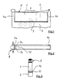
- a valve 1 is connected to a base plate 2. Between the base plate 2 and the valve 1 run - indicated here by dashed lines - various channels 3 to Supply or disposal of the valve 1 with feed pressure or exhaust air.
- the base plate 2 further comprises two mutually spaced support arms 4a and 4b on. Both holder arms 4a and 4b are directly on the existing plastic Base plate 2 formed. Extends between the distal ends of both holder arms 4a and 4b a leaf spring 5 along the upper longitudinal surface 6 of the valve 1.
- the leaf spring 5 is closed one end pivotally mounted on the associated holder arm 4b to a Assembly / disassembly of the valve 1 with / from the base plate 2 with the leaf spring pivoted away 5 to allow.
- the required for attachment of the valve 1 to the base plate Compressive force brings the leaf spring 5 via a central pressure area 7.
- the leaf spring 5 Insofar consists of a punched spring steel piece of sheet metal, to achieve the required bias is given a curved shape.
- the leaf spring 5 is connected to the end associated with the holder arm 4 a via a Holding / releasing mechanism 8 removably attached thereto.
- the holding / releasing mechanism 8 works in the manner of a spring detent mechanism.
- compression in Arrow direction
- two hook legs 9a and 9b these are in accordance with a corresponding opening 10 is brought into the leaf spring 5, so that the two Hook legs 9a and 9b can pass through the window-like opening 10 to to release the leaf spring 5 from the holder arm 4a.
- Fig. 3 is a surface sealing element 11 between the valve 1 and the Base plate 2 for sealing the - not shown here - corresponding Channels against each other and against the atmosphere provided.
- valve 1 in the assembled state immovable with the corresponding Base plate 2 remains in communication, are between the valve 1 and the base plate.
- form-locking interlocking fixing means 12 are provided here by geometric Formations and recesses are formed.
Landscapes
- Engineering & Computer Science (AREA)
- General Engineering & Computer Science (AREA)
- Mechanical Engineering (AREA)
- Physics & Mathematics (AREA)
- Fluid Mechanics (AREA)
- Valve Housings (AREA)
- Safety Valves (AREA)
- Control Of Transmission Device (AREA)
Applications Claiming Priority (2)
| Application Number | Priority Date | Filing Date | Title |
|---|---|---|---|
| DE102004019768A DE102004019768B4 (de) | 2004-04-23 | 2004-04-23 | Grundplatte mit einer Vorrichtung zur lösbaren Befestigung eines Ventils |
| DE102004019768 | 2004-04-23 |
Publications (2)
| Publication Number | Publication Date |
|---|---|
| EP1589269A2 true EP1589269A2 (fr) | 2005-10-26 |
| EP1589269A3 EP1589269A3 (fr) | 2006-03-15 |
Family
ID=34939451
Family Applications (1)
| Application Number | Title | Priority Date | Filing Date |
|---|---|---|---|
| EP05103268A Withdrawn EP1589269A3 (fr) | 2004-04-23 | 2005-04-22 | Dispositif pour fixation amovible d'une soupape sur une plaque de base |
Country Status (2)
| Country | Link |
|---|---|
| EP (1) | EP1589269A3 (fr) |
| DE (1) | DE102004019768B4 (fr) |
Family Cites Families (16)
| Publication number | Priority date | Publication date | Assignee | Title |
|---|---|---|---|---|
| US600670A (en) * | 1898-03-15 | Millaed f | ||
| US2869098A (en) * | 1955-07-25 | 1959-01-13 | Comar Electric Company | Strap type instrument mounting |
| FR1379771A (fr) * | 1963-10-17 | 1964-11-27 | Sigma | Perfectionnements apportés aux distributeurs de fluide à tiroir coulissant et électro-aimant de commande |
| DE1211453B (de) * | 1964-02-11 | 1966-02-24 | Erich Herion | Schnellverschluss fuer Ventile mit geteiltem Gehaeuse |
| FR1462938A (fr) * | 1965-01-09 | 1966-12-16 | Bosch Gmbh Robert | Dispositif d'accouplement rapide de carters et carters équipés de ce dispositif |
| CH552755A (de) * | 1972-06-15 | 1974-08-15 | Westinghouse Brake & Signal | Ventilbatterie. |
| CH577653A5 (fr) * | 1974-04-02 | 1976-07-15 | Interapp Gmbh | |
| DE2516438A1 (de) * | 1975-04-15 | 1976-10-28 | Herion Werke Kg | Vorrichtung zum aufbau von steuerungen |
| GB1577159A (en) * | 1977-11-16 | 1980-10-22 | Sanyo Kiki Kk | Hydraulic control apparatus |
| JP2603160B2 (ja) * | 1990-12-29 | 1997-04-23 | エスエムシー株式会社 | 弁取付装置 |
| DE4112463A1 (de) * | 1991-04-12 | 1992-10-15 | Mannesmann Ag | Ventilanordnung fuer druckmedien |
| FR2720236A3 (fr) * | 1995-05-24 | 1995-12-01 | Lin Chin Ju | Dents disposées sur une pince à cheveux pour renforcer l'action de serrage des cheveux et susceptibles de peigner les cheveux. |
| EP1032058A1 (fr) * | 1999-02-25 | 2000-08-30 | Lucent Technologies Inc. | Boíte de batterie améliorée |
| US6523570B2 (en) * | 2000-05-04 | 2003-02-25 | Parker-Hannifin Corp. | Manifold for valve assembly |
| JP3863769B2 (ja) * | 2001-12-04 | 2006-12-27 | Smc株式会社 | 電磁弁用マニホールド |
| JP2004360864A (ja) * | 2003-06-06 | 2004-12-24 | Toyota Motor Corp | 電磁弁組立体の誤組み付け防止構造 |
-
2004
- 2004-04-23 DE DE102004019768A patent/DE102004019768B4/de not_active Expired - Fee Related
-
2005
- 2005-04-22 EP EP05103268A patent/EP1589269A3/fr not_active Withdrawn
Non-Patent Citations (1)
| Title |
|---|
| Produktkatalog "Das Pneumatik-Programm von Bosch" (Ausgabe 15.31, Drucknummer 1 987 765 015, Auflage 1998.02, Datenblatt 15.31/5.111) |
Also Published As
| Publication number | Publication date |
|---|---|
| EP1589269A3 (fr) | 2006-03-15 |
| DE102004019768B4 (de) | 2010-09-02 |
| DE102004019768A1 (de) | 2005-11-10 |
Similar Documents
| Publication | Publication Date | Title |
|---|---|---|
| DE69124736T2 (de) | Ventilverteiler | |
| DE60209140T2 (de) | Verbindungselement | |
| EP1140437A1 (fr) | Tondeuse a cheveux | |
| WO2008138613A1 (fr) | Étrier de verrouillage pour boîtier de connecteur électrique | |
| EP2485870B1 (fr) | Dispositif de serrage | |
| EP3425248A1 (fr) | Servomoteur pour soupapes de processus | |
| DE19801234C2 (de) | Ventileinheit | |
| EP1616104B1 (fr) | Element de fixation et couvercle, adapte a ce dernier, d'un verin hydraulique | |
| EP1589269A2 (fr) | Dispositif pour fixation amovible d'une soupape sur une plaque de base | |
| DE102021122008A1 (de) | Scharnier sowie Türanordnung und Verfahren zur Befestigung einer Tür | |
| DE102021107264A1 (de) | Auftragsvorrichtung | |
| DE19840700C2 (de) | Ventileinheit | |
| DE102007057413B4 (de) | Druckmittelzylinder mit Zylinderdeckelanordnungen | |
| EP1464741B1 (fr) | Systeme à cylindre de pression à double pression, et dispositif de contrôle des fibres dans une machine textile avec un tel système à cylindre de pression à double pression | |
| DE202005005908U1 (de) | Elektrisch betätigbares Ventil | |
| DE10223936B4 (de) | Pneumatikaggregat mit mindestens einer Anschlussbuchse für eine Druckmittelleitung | |
| DE19803513A1 (de) | Modulare Endstellungsabfrageeinrichtung | |
| EP3189256B1 (fr) | Clip de fixation et soupape équipée de ce dernier | |
| DE102005020185B4 (de) | Ventilanordnung | |
| EP2722471A2 (fr) | Ferrure pour battant et séparation de douche | |
| EP2578891A1 (fr) | Adapteur | |
| EP1306597B1 (fr) | Soupape | |
| DE10159182A1 (de) | Ventileinheit mit einem geräuscharmen Entlüftungskanal | |
| DE102007040003A1 (de) | Steckanschlussvorrichtung für eine pneumatische Druckleitung | |
| EP1801476A2 (fr) | Plaque de raccordement de distributeur pneumatique doté d'un support variable des raccordements de travail |
Legal Events
| Date | Code | Title | Description |
|---|---|---|---|
| PUAI | Public reference made under article 153(3) epc to a published international application that has entered the european phase |
Free format text: ORIGINAL CODE: 0009012 |
|
| AK | Designated contracting states |
Kind code of ref document: A2 Designated state(s): AT BE BG CH CY CZ DE DK EE ES FI FR GB GR HU IE IS IT LI LT LU MC NL PL PT RO SE SI SK TR |
|
| AX | Request for extension of the european patent |
Extension state: AL BA HR LV MK YU |
|
| PUAL | Search report despatched |
Free format text: ORIGINAL CODE: 0009013 |
|
| AK | Designated contracting states |
Kind code of ref document: A3 Designated state(s): AT BE BG CH CY CZ DE DK EE ES FI FR GB GR HU IE IS IT LI LT LU MC NL PL PT RO SE SI SK TR |
|
| AX | Request for extension of the european patent |
Extension state: AL BA HR LV MK YU |
|
| 17P | Request for examination filed |
Effective date: 20060412 |
|
| RAP1 | Party data changed (applicant data changed or rights of an application transferred) |
Owner name: BOSCH REXROTH AG |
|
| AKX | Designation fees paid |
Designated state(s): AT BE BG CH CY CZ DE DK EE ES FI FR GB GR HU IE IS IT LI LT LU MC NL PL PT RO SE SI SK TR |
|
| STAA | Information on the status of an ep patent application or granted ep patent |
Free format text: STATUS: THE APPLICATION IS DEEMED TO BE WITHDRAWN |
|
| 18D | Application deemed to be withdrawn |
Effective date: 20071101 |