EP1589269A2 - Device for releasable attaching a valve to a base plate - Google Patents
Device for releasable attaching a valve to a base plate Download PDFInfo
- Publication number
- EP1589269A2 EP1589269A2 EP05103268A EP05103268A EP1589269A2 EP 1589269 A2 EP1589269 A2 EP 1589269A2 EP 05103268 A EP05103268 A EP 05103268A EP 05103268 A EP05103268 A EP 05103268A EP 1589269 A2 EP1589269 A2 EP 1589269A2
- Authority
- EP
- European Patent Office
- Prior art keywords
- valve
- base plate
- leaf spring
- spring
- holding
- Prior art date
- Legal status (The legal status is an assumption and is not a legal conclusion. Google has not performed a legal analysis and makes no representation as to the accuracy of the status listed.)
- Withdrawn
Links
- 238000007789 sealing Methods 0.000 claims description 7
- 229910000639 Spring steel Inorganic materials 0.000 claims description 3
- 238000003825 pressing Methods 0.000 claims description 2
- 239000000243 solution Substances 0.000 description 5
- 238000005516 engineering process Methods 0.000 description 2
- 238000004519 manufacturing process Methods 0.000 description 2
- 229910052751 metal Inorganic materials 0.000 description 2
- 239000002184 metal Substances 0.000 description 2
- 229910052782 aluminium Inorganic materials 0.000 description 1
- XAGFODPZIPBFFR-UHFFFAOYSA-N aluminium Chemical compound [Al] XAGFODPZIPBFFR-UHFFFAOYSA-N 0.000 description 1
- 230000009286 beneficial effect Effects 0.000 description 1
- 230000005540 biological transmission Effects 0.000 description 1
- 230000015572 biosynthetic process Effects 0.000 description 1
- 238000004891 communication Methods 0.000 description 1
- 230000006835 compression Effects 0.000 description 1
- 238000007906 compression Methods 0.000 description 1
- 238000010276 construction Methods 0.000 description 1
- 230000001419 dependent effect Effects 0.000 description 1
- 238000011161 development Methods 0.000 description 1
- 230000018109 developmental process Effects 0.000 description 1
- 238000005755 formation reaction Methods 0.000 description 1
- 238000002347 injection Methods 0.000 description 1
- 239000007924 injection Substances 0.000 description 1
- 238000001746 injection moulding Methods 0.000 description 1
- 230000003993 interaction Effects 0.000 description 1
- 239000000463 material Substances 0.000 description 1
- 238000000034 method Methods 0.000 description 1
- 238000000465 moulding Methods 0.000 description 1
- 238000002360 preparation method Methods 0.000 description 1
Images
Classifications
-
- F—MECHANICAL ENGINEERING; LIGHTING; HEATING; WEAPONS; BLASTING
- F16—ENGINEERING ELEMENTS AND UNITS; GENERAL MEASURES FOR PRODUCING AND MAINTAINING EFFECTIVE FUNCTIONING OF MACHINES OR INSTALLATIONS; THERMAL INSULATION IN GENERAL
- F16K—VALVES; TAPS; COCKS; ACTUATING-FLOATS; DEVICES FOR VENTING OR AERATING
- F16K27/00—Construction of housing; Use of materials therefor
- F16K27/003—Housing formed from a plurality of the same valve elements
-
- F—MECHANICAL ENGINEERING; LIGHTING; HEATING; WEAPONS; BLASTING
- F15—FLUID-PRESSURE ACTUATORS; HYDRAULICS OR PNEUMATICS IN GENERAL
- F15B—SYSTEMS ACTING BY MEANS OF FLUIDS IN GENERAL; FLUID-PRESSURE ACTUATORS, e.g. SERVOMOTORS; DETAILS OF FLUID-PRESSURE SYSTEMS, NOT OTHERWISE PROVIDED FOR
- F15B13/00—Details of servomotor systems ; Valves for servomotor systems
- F15B13/02—Fluid distribution or supply devices characterised by their adaptation to the control of servomotors
- F15B13/06—Fluid distribution or supply devices characterised by their adaptation to the control of servomotors for use with two or more servomotors
- F15B13/08—Assemblies of units, each for the control of a single servomotor only
- F15B13/0803—Modular units
- F15B13/0807—Manifolds
- F15B13/0814—Monoblock manifolds
-
- F—MECHANICAL ENGINEERING; LIGHTING; HEATING; WEAPONS; BLASTING
- F15—FLUID-PRESSURE ACTUATORS; HYDRAULICS OR PNEUMATICS IN GENERAL
- F15B—SYSTEMS ACTING BY MEANS OF FLUIDS IN GENERAL; FLUID-PRESSURE ACTUATORS, e.g. SERVOMOTORS; DETAILS OF FLUID-PRESSURE SYSTEMS, NOT OTHERWISE PROVIDED FOR
- F15B13/00—Details of servomotor systems ; Valves for servomotor systems
- F15B13/02—Fluid distribution or supply devices characterised by their adaptation to the control of servomotors
- F15B13/06—Fluid distribution or supply devices characterised by their adaptation to the control of servomotors for use with two or more servomotors
- F15B13/08—Assemblies of units, each for the control of a single servomotor only
- F15B13/0803—Modular units
- F15B13/0821—Attachment or sealing of modular units to each other
-
- F—MECHANICAL ENGINEERING; LIGHTING; HEATING; WEAPONS; BLASTING
- F15—FLUID-PRESSURE ACTUATORS; HYDRAULICS OR PNEUMATICS IN GENERAL
- F15B—SYSTEMS ACTING BY MEANS OF FLUIDS IN GENERAL; FLUID-PRESSURE ACTUATORS, e.g. SERVOMOTORS; DETAILS OF FLUID-PRESSURE SYSTEMS, NOT OTHERWISE PROVIDED FOR
- F15B13/00—Details of servomotor systems ; Valves for servomotor systems
- F15B13/02—Fluid distribution or supply devices characterised by their adaptation to the control of servomotors
- F15B13/06—Fluid distribution or supply devices characterised by their adaptation to the control of servomotors for use with two or more servomotors
- F15B13/08—Assemblies of units, each for the control of a single servomotor only
- F15B13/0803—Modular units
- F15B13/0828—Modular units characterised by sealing means of the modular units
-
- F—MECHANICAL ENGINEERING; LIGHTING; HEATING; WEAPONS; BLASTING
- F15—FLUID-PRESSURE ACTUATORS; HYDRAULICS OR PNEUMATICS IN GENERAL
- F15B—SYSTEMS ACTING BY MEANS OF FLUIDS IN GENERAL; FLUID-PRESSURE ACTUATORS, e.g. SERVOMOTORS; DETAILS OF FLUID-PRESSURE SYSTEMS, NOT OTHERWISE PROVIDED FOR
- F15B13/00—Details of servomotor systems ; Valves for servomotor systems
- F15B13/02—Fluid distribution or supply devices characterised by their adaptation to the control of servomotors
- F15B13/06—Fluid distribution or supply devices characterised by their adaptation to the control of servomotors for use with two or more servomotors
- F15B13/08—Assemblies of units, each for the control of a single servomotor only
- F15B13/0803—Modular units
- F15B13/0875—Channels for electrical components, e.g. for cables or sensors
Definitions
- the invention relates to a device for releasably securing a valve to a the Valve via corresponding channels for pressure medium and / or Anêtsignalchuck connecting base plate.
- valves which for the purpose of connection to a compressed air supply and disposal of a corresponding Associated with connections base plate are assigned.
- the base plate can be special
- electrical line means which the electrical Connection of the valves for the transmission of the control signals to an electromagnetic Drive serve.
- multiple valve base plate pairings become one Valve block strung together.
- the valve block thus represents a locally summarized Concentration of several valves for admission of subordinate pressure medium aggregates - Such as pressure cylinder - is.
- valve block is opened of the type explained above.
- the individual valve-base plate pairings are made via tie rod screw connections, which have long since passed through all the base plates, fastened together.
- the attachment of each Valve on the associated base plate also takes place via a screw connection.
- two spaced-apart screws are provided per valve, which by a through hole can be inserted through the valve to enter into the to be screwed in corresponding base plate.
- valve housings and base plates are manufacturing technology quite simply by injection molding let produce.
- Another trend in the technical field of pneumatics is increasing ever narrower valves, to the compactness of this by stringing together increase built valve blocks.
- the conventional encounters screw fastening solution for valves to associated base plates Feasibility limits. Because there is barely enough space on the part of narrow base plates for introducing a reliably cooperating with the screw Threaded bottom hole available. Minimum material thicknesses are required so that the existing plastic threads the prevailing loads withstand. Furthermore, it can easily over-tighten the screws when screwing in the plastic base plate come.
- the use of injected Threaded metal sleeves for the preparation of the threaded base hole in turn requires in view of the narrow construction technique too much space.
- the invention includes the technical teaching that extends along an upper longitudinal surface of the narrow-building valve, a leaf spring extending, which at both ends with the Base plate is in stationary connection and has a central pressure area between the ends exert a force for pressing the valve to the base plate, so that mutually corresponding channels between valve and base plate pressure-tight get in touch with each other.
- the advantage of the solution according to the invention lies in the fact that the so the base plate attached valves are easily assembled and disassembled. Because the attached to the base plate leaf spring is because of their arrangement at the top Longitudinal surface of the valve particularly well accessible. Since no fasteners between the valve and the corresponding base plate are present, is the inventive solution for particularly slim-fitting valve base plate pairings suitable.
- the attachment of the leaf spring to the base plate via two, depending arranged frontally to the valve and towards the area of the upper longitudinal surface extending bracket arms.
- the holder arms can by injection preferably Made of plastic base plate to be molded with, so the extra Production costs remain minimal.
- the two form each end of the Valve extending bracket arms a fairly good guide for the valve, preferably this comes directly to the plant.
- the leaf spring should be to realize a simple assembly / disassembly to one end pivotally mounted on the associated holder arm.
- Another advantage of this arrangement is that the leaf spring is thus captively attached to a support arm of the base plate.
- the pivotal attachment of the leaf spring on the associated holder arm can in particular be easily prepared by means of a pinning.
- the opposite support arm at its distal end with a holding / releasing mechanism equipped in the manner of a spring detent mechanism. This is the leaf spring without additional tool can be locked.
- Said holding / releasing mechanism is preferably made of two opposite one Spring force collapsible hook legs, which are in the relaxed state behind Hook a window-like opening of the leaf spring. A release is done by Squeezing the two hook legs so that they pass through the opening reach and the leaf spring can be removed.
- both holder arms with such a holding / releasing mechanism equip what may be beneficial in very limited space.
- the leaf spring according to the invention preferably consists of a punched out Spring steel sheet piece, which to achieve a sufficient bias one arched shape is awarded.
- This special design of the leaf spring can be Apply enough pressure for the valve in the direction of the base plate to make a pressure-tight connection.
- Another measure improving the invention provides that the Orientation of the valve with respect to the associated base plate in between arranged and positively interlocking means may be provided.
- These positively interlocking means may for example in the form of pin-like Moldings are formed by the base plate, which in corresponding Recesses on the part of the valve intervene without clearance.
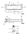
- a valve 1 is connected to a base plate 2. Between the base plate 2 and the valve 1 run - indicated here by dashed lines - various channels 3 to Supply or disposal of the valve 1 with feed pressure or exhaust air.
- the base plate 2 further comprises two mutually spaced support arms 4a and 4b on. Both holder arms 4a and 4b are directly on the existing plastic Base plate 2 formed. Extends between the distal ends of both holder arms 4a and 4b a leaf spring 5 along the upper longitudinal surface 6 of the valve 1.
- the leaf spring 5 is closed one end pivotally mounted on the associated holder arm 4b to a Assembly / disassembly of the valve 1 with / from the base plate 2 with the leaf spring pivoted away 5 to allow.
- the required for attachment of the valve 1 to the base plate Compressive force brings the leaf spring 5 via a central pressure area 7.
- the leaf spring 5 Insofar consists of a punched spring steel piece of sheet metal, to achieve the required bias is given a curved shape.
- the leaf spring 5 is connected to the end associated with the holder arm 4 a via a Holding / releasing mechanism 8 removably attached thereto.
- the holding / releasing mechanism 8 works in the manner of a spring detent mechanism.
- compression in Arrow direction
- two hook legs 9a and 9b these are in accordance with a corresponding opening 10 is brought into the leaf spring 5, so that the two Hook legs 9a and 9b can pass through the window-like opening 10 to to release the leaf spring 5 from the holder arm 4a.
- Fig. 3 is a surface sealing element 11 between the valve 1 and the Base plate 2 for sealing the - not shown here - corresponding Channels against each other and against the atmosphere provided.
- valve 1 in the assembled state immovable with the corresponding Base plate 2 remains in communication, are between the valve 1 and the base plate.
- form-locking interlocking fixing means 12 are provided here by geometric Formations and recesses are formed.
Landscapes
- Engineering & Computer Science (AREA)
- General Engineering & Computer Science (AREA)
- Mechanical Engineering (AREA)
- Physics & Mathematics (AREA)
- Fluid Mechanics (AREA)
- Valve Housings (AREA)
- Safety Valves (AREA)
- Control Of Transmission Device (AREA)
Abstract
Description
Die Erfindung betrifft eine Vorrichtung zur lösbaren Befestigung eines Ventils an einer das Ventil über korrespondierende Kanäle zur Druckmittel- und/oder Ansteuersignalversorgung verbindenden Grundplatte.The invention relates to a device for releasably securing a valve to a the Valve via corresponding channels for pressure medium and / or Ansteuersignalversorgung connecting base plate.
Insbesondere auf dem technischen Gebiet der Pneumatik werden Ventile verwendet, welche zwecks Anschluss an eine Druckluftversorgung und -entsorgung einer entsprechende Anschlüsse aufweisenden Grundplatte zugeordnet sind. Die Grundplatte kann in speziellen Einsatzfällen daneben auch elektrische Leitungsmittel beherbergen, welche dem elektrischen Anschluss der Ventile zur Übertragung der Ansteuersignale an einen elektromagnetischen Antrieb dienen. Gewöhnlich werden mehrere Ventil-Grundplatten-Paarungen zu einem Ventilblock aneinandergereiht. Der Ventilblock stellt somit eine örtlich zusammengefasste Konzentration mehrerer Ventile zur Beaufschlagung nachgeordneter Druckmittelaggregate - wie beispielsweise Druckmittelzylinder - dar.In particular, in the technical field of pneumatics valves are used, which for the purpose of connection to a compressed air supply and disposal of a corresponding Associated with connections base plate are assigned. The base plate can be special In addition applications also accommodate electrical line means which the electrical Connection of the valves for the transmission of the control signals to an electromagnetic Drive serve. Usually, multiple valve base plate pairings become one Valve block strung together. The valve block thus represents a locally summarized Concentration of several valves for admission of subordinate pressure medium aggregates - Such as pressure cylinder - is.
Aus dem Produktkatalog "Das Pneumatik-Programm von Bosch" (Ausgabe 15.31,
Drucknummer 1 987 765 015, Auflage 1998.02, Datenblatt 15.31/5.111) geht ein Ventilblock
der vorstehend erläuterten Art hervor. Konkret werden hier mehrere elektrisch betätigbare
Wegeventilen mit jeweils zugeordneten Grundplatten zu dem Ventilblock zusammengefasst.
Die einzelnen Ventil-Grundplatten-Paarungen werden über Zuganker-Verschraubungen,
welche längst durch alle Grundplatten verlaufen, aneinander befestigt. Die Befestigung jedes
Ventils an der zugeordneten Grundplatte erfolgt ebenfalls über eine Schraubverbindung.
Hierfür sind je Ventil zwei voneinander beabstandete Schrauben vorgesehen, welche durch
eine Durchgangsbohrung seitens des Ventils hindurch gesteckt werden, um in die
korrespondierende Grundplatte eingeschraubt zu werden. Diese Befestigungslösung stellt bei
der vorliegenden Ventil-Grundplatten-Paarung die optimale Lösung dar, da eine einfache
Montage mit einer zuverlässigen Verbindungstechnik sichergestellt ist. Denn die
Grundplatten selbst bestehen hier aus Aluminium, so dass die in die Grundplatte
eingebrachten Gewindegrundbohrungen ein sicheres Zusammenwirken mit den
Gewindegängen der Schraube gewährleisten.From the product catalog "The Pneumatic Program from Bosch" (Issue 15.31,
In jüngster Zeit geht der Trend bei Ventilgehäusen und Grundplatten vermehrt zu Kunststoffausführungen, welche sich fertigungstechnisch recht einfach durch Spritzgießen herstellen lassen. Ein weiterer Trend auf dem technischen Gebiet der Pneumatik geht zu immer schmalbauenderen Ventilen, um die Kompaktheit von hieraus durch Aneinanderreihen aufgebauten Ventilblöcken zu erhöhen. In Folge beider Trends stößt die herkömmliche schraubende Befestigungslösung für Ventile an zugeordnete Grundplatten an Machbarkeitsgrenzen. Denn es steht kaum ausreichend Platz seitens schmaler Grundplatten zur Einbringung einer zuverlässig mit der Schraube zusammenwirkenden Gewindegrundbohrung zur Verfügung. Hierbei sind Mindestmaterialdicken erforderlich, damit die aus Kunststoff bestehenden Gewindegänge den herrschenden Belastungen standhalten. Ferner kann es leicht zu einem Überdrehen der Schrauben beim Einschrauben in die aus Kunststoff bestehende Grundplatte kommen. Die Verwendung von eingespritzten Gewindemetallhülsen zur Herstellung der Gewindegrundbohrung erfordert wiederum angesichts der Schmalbautechnik zu viel Bauraum.Recently, the trend in valve housings and base plates is increasing Plastic versions, which are manufacturing technology quite simply by injection molding let produce. Another trend in the technical field of pneumatics is increasing ever narrower valves, to the compactness of this by stringing together increase built valve blocks. As a result of both trends, the conventional encounters screw fastening solution for valves to associated base plates Feasibility limits. Because there is barely enough space on the part of narrow base plates for introducing a reliably cooperating with the screw Threaded bottom hole available. Minimum material thicknesses are required so that the existing plastic threads the prevailing loads withstand. Furthermore, it can easily over-tighten the screws when screwing in the plastic base plate come. The use of injected Threaded metal sleeves for the preparation of the threaded base hole in turn requires in view of the narrow construction technique too much space.
Es ist daher die Aufgabe der vorliegenden Erfindung eine zuverlässige Vorrichtung zur lösbaren Befestigung eines Ventils an einer Grundplatte zu schaffen, die sich insbesondere für schmalbauende Ventile eignet, und die in einfacher Weise die erforderlichen Befestigungskräfte bei der Ventil- Grundplatte- Paarung zur Verfügung stellt.It is therefore the object of the present invention to provide a reliable device for releasable attachment of a valve to a base plate to create, in particular for slim-fitting valves, and in a simple way the required Mounting forces in the valve base plate pairing provides.
Die Aufgabe wir ausgehend von einer Vorrichtung gemäß dem Oberbegriff des Anspruchs 1
in Verbindung mit dessen kennzeichnenden Merkmalen gelöst. Die nachfolgenden
abhängigen Ansprüche geben vorteilhafte Weiterbildungen der Erfindung wieder.The object we are starting from a device according to the preamble of
Die Erfindung schließt die technische Lehre ein, dass sich entlang einer oberen Längsfläche des schmalbauenden Ventils eine Blattfeder erstreckt, die zu beiden Enden mit der Grundplatte in ortsfester Verbindung steht und über einen zentralen Druckbereich zwischen den Enden eine Kraft zum Andrücken des Ventils an die Grundplatte ausübt, so dass miteinander korrespondierenden Kanäle zwischen Ventil und Grundplatte druckdicht miteinander in Verbindung kommen. The invention includes the technical teaching that extends along an upper longitudinal surface of the narrow-building valve, a leaf spring extending, which at both ends with the Base plate is in stationary connection and has a central pressure area between the ends exert a force for pressing the valve to the base plate, so that mutually corresponding channels between valve and base plate pressure-tight get in touch with each other.
Der Vorteil der erfindungsgemäßen Lösung liegt insbesondere darin, dass die dergestalt an der Grundplatte befestigten Ventile in einfacher Weise montierbar und demontierbar sind. Denn die an der Grundplatte angebrachte Blattfeder ist wegen ihrer Anordnung an der oberen Längsfläche des Ventils besonders gut zugänglich. Da keine Befestigungsmittel zwischen dem Ventil und der korrespondierenden Grundplatte vorhanden sind, ist die erfindungsgemäße Lösung für besonders schmalbauende Ventil- Grundplatte- Paarungen geeignet.The advantage of the solution according to the invention lies in the fact that the so the base plate attached valves are easily assembled and disassembled. Because the attached to the base plate leaf spring is because of their arrangement at the top Longitudinal surface of the valve particularly well accessible. Since no fasteners between the valve and the corresponding base plate are present, is the inventive solution for particularly slim-fitting valve base plate pairings suitable.
Vorzugsweise erfolgt die Befestigung der Blattfeder an der Grundplatte über zwei, je stirnseitig zum Ventil angeordnete und sich zum Bereich der oberen Längsfläche hin erstreckende Halterarme. Die Halterarme können dabei durch Spritzgießen der vorzugsweise aus Kunststoffbestehenden Grundplatte mit angeformt werden, so dass der zusätzliche Herstellungsaufwand recht minimal bleibt. Weiterhin bilden die beiden sich je stirnseitig des Ventils erstreckenden Halterarme eine recht gute Führung für das Ventil, das vorzugsweise hieran direkt zur Anlage kommt.Preferably, the attachment of the leaf spring to the base plate via two, depending arranged frontally to the valve and towards the area of the upper longitudinal surface extending bracket arms. The holder arms can by injection preferably Made of plastic base plate to be molded with, so the extra Production costs remain minimal. Furthermore, the two form each end of the Valve extending bracket arms a fairly good guide for the valve, preferably this comes directly to the plant.
Die Blattfeder sollte zur Realisierung einer einfachen Montage/Demontage zum einen Ende hin schwenkbar am zugeordneten Halterarm angebracht sein. Somit ist die Montage beziehungsweise Demontage des Ventils mit/von der Grundplatte in einfacher Weise bei weggeschwenkter Blattfeder möglich. Ein weiterer Vorteil dieser Anordnung besteht darin, dass die Blattfeder somit unverlierbar an einem Halterarm der Grundplatte angebracht ist. Die schwenkbare Befestigung der Blattfeder am zugeordneten Halterarm kann in besonders einfacher Weise mittels einer Verstiftung hergestellt werden.The leaf spring should be to realize a simple assembly / disassembly to one end pivotally mounted on the associated holder arm. Thus, the assembly or disassembly of the valve with / from the base plate in a simple manner weggeschwenkter leaf spring possible. Another advantage of this arrangement is that the leaf spring is thus captively attached to a support arm of the base plate. The pivotal attachment of the leaf spring on the associated holder arm can in particular be easily prepared by means of a pinning.
Gemäß einer weiteren die Erfindung verbessernden Maßnahme ist vorgesehen, dass der gegenüberliegende Halterarm an seinem distalen Ende mit einem Halte/Lösemechanismus nach Art eines Federrastmechanismus ausgestattet ist. Hieran ist die Blattfeder ohne zusätzliches Werkzeug arretierbar. According to a further measure improving the invention it is provided that the opposite support arm at its distal end with a holding / releasing mechanism equipped in the manner of a spring detent mechanism. This is the leaf spring without additional tool can be locked.
Der besagte Halte/Lösemechanismus besteht vorzugsweise aus zwei entgegen einer Federkraft zusammendrückbaren Hakenschenkeln, die sich im entspannten Zustand hinter einer fensterartigen Öffnung der Blattfeder einhaken. Ein Lösen erfolgt durch Zusammendrücken der beiden Hakenschenkel, so dass diese durch die Öffnung hindurch gelangen und sich die Blattfeder entfernen lässt. Natürlich ist es im Rahmen der vorliegenden Erfindung auch denkbar, beide Halterarme mit einem derartigen Halte/Lösemechanismus auszustatten, was eventuell bei sehr begrenzten Platzverhältnissen von Vorteil sein kann.Said holding / releasing mechanism is preferably made of two opposite one Spring force collapsible hook legs, which are in the relaxed state behind Hook a window-like opening of the leaf spring. A release is done by Squeezing the two hook legs so that they pass through the opening reach and the leaf spring can be removed. Of course it is within the present Invention also conceivable, both holder arms with such a holding / releasing mechanism equip what may be beneficial in very limited space.
Die erfindungsgemäße Blattfeder besteht vorzugsweise aus einem ausgestanzten Federstahlblechstück, welchem zur Erzielung einer ausreichenden Vorspannung eine gewölbte Gestalt verliehen ist. Durch diese spezielle Ausführung der Blattfeder lassen sich genügend große Andrückkräfte für das Ventil in Richtung der Grundplatte aufbringen, um eine druckdichte Verbindung herzustellen. Zusätzlich ist es ratsam, im Kontaktbereich zwischen dem Ventil und der zugeordneten Grundplatte mindestens ein Dichtungselement zur Abdichtung der korrespondierenden Kanäle gegeneinander und gegenüber der Atmosphäre anzuordnen.The leaf spring according to the invention preferably consists of a punched out Spring steel sheet piece, which to achieve a sufficient bias one arched shape is awarded. This special design of the leaf spring can be Apply enough pressure for the valve in the direction of the base plate to make a pressure-tight connection. In addition, it is advisable in the contact area between the valve and the associated base plate at least one sealing element for Sealing the corresponding channels against each other and with respect to the atmosphere to arrange.
Eine andere die Erfmdung verbessernde Maßnahme sieht vor, dass zur eindeutigen Lagebestimmung des Ventils gegenüber der zugeordneten Grundplatte dazwischen angeordnete und formschlüssig ineinandergreifende Mittel vorgesehen sein können. Diese formschlüssig ineinandergreifenden Mittel können beispielsweise in Form von stiftartigen Anformungen seitens der Grundplatte ausgebildet werden, die in korrespondierende Ausnehmungen seitens des Ventils spielfrei eingreifen.Another measure improving the invention provides that the Orientation of the valve with respect to the associated base plate in between arranged and positively interlocking means may be provided. These positively interlocking means may for example in the form of pin-like Moldings are formed by the base plate, which in corresponding Recesses on the part of the valve intervene without clearance.
Weitere die Erfindung verbessernde Maßnahmen werden nachstehend gemeinsam mit der Beschreibung eines bevorzugten Ausführungsbeispiels der Erfindung anhand der Figuren näher dargestellt. Es zeigt:
- Fig.1
- eine Seitenansicht einer Ventil- Grundplatte- Paarung mit einer Vorrichtung zur lösbaren Befestigung beider Verbindungspartner,
- Fig. 2
- eine Draufsicht auf die Ventil-Grundplatten-Paarung gemäß Fig. 1,
- Fig. 3
- eine Seitenansicht der Ventil-Grundplatten-Paarung gemäß Fig. 1 im Bereich des Halte/Lösemechanismus.
- Fig.1
- a side view of a valve base plate pairing with a device for releasably securing both connection partners,
- Fig. 2
- a plan view of the valve base plate pairing of FIG. 1,
- Fig. 3
- a side view of the valve base plate pairing of FIG. 1 in the region of the holding / releasing mechanism.
Gemäß Fig. 1 ist ein Ventil 1 mit einer Grundplatte 2 verbunden. Zwischen der Grundplatte 2
und dem Ventil 1 verlaufen - hier durch Strichlinien angedeutet - diverse Kanäle 3 zur
Versorgung oder Entsorgung des Ventils 1 mit Speisedruck beziehungsweise Abluft.According to FIG. 1, a
Die Grundplatte 2 weist weiterhin zwei beabstandet voneinander angeordnete Halterarme 4a
und 4b auf. Beide Halterarme 4a und 4b sind direkt an die aus Kunststoff bestehende
Grundplatte 2 angeformt. Zwischen den distalen Enden beider Halterarme 4a und 4b erstreckt
sich eine Blattfeder 5 entlang der oberen Längsfläche 6 des Ventils 1. Die Blattfeder 5 ist zu
einem Ende hin schwenkbar am zugeordneten Halterarm 4b gelagert, um eine
Montage/Demontage des Ventils 1 mit/von der Grundplatte 2 bei weggeschwenkter Blattfeder
5 zu ermöglichen. Die zur Befestigung des Ventils 1 an der Grundplatte erforderliche
Druckkraft bringt die Blattfeder 5 über einen zentralen Druckbereich 7 auf. Die Blattfeder 5
besteht insoweit aus einem ausgestanzten Federstahlblechstück, dem zur Erzielung der
erforderlichen Vorspannung eine gewölbte Gestalt verliehen ist.The
Gemäß Fig. 2 ist die Blattfeder 5 an dem dem Halterarm 4a zugeordneten Ende über einen
Halte/Lösemechanismus 8 lösbar hieran angebracht. Der Halte/Lösemechanismus 8
funktioniert nach Art eines Federrastmechanismus. Durch Zusammendrücken (in
Pfeilrichtung) zweier Hakenschenkel 9a und 9b werden diese in Übereinstimmung mit einer
korrespondierenden Öffnung 10 in der Blattfeder 5 gebracht, so dass die beiden
Hakenschenkel 9a und 9b durch die fensterartige Öffnung 10 hindurchgelangen können, um
die Blattfeder 5 vom Halterarm 4a zu lösen.According to FIG. 2, the
Nach Fig. 3 ist ein flächenübergreifendes Dichtelement 11 zwischen dem Ventil 1 und der
Grundplatte 2 zur Abdichtung der - hier nicht weiter dargestellten - korrespondierenden
Kanäle gegeneinander und gegenüber der Atmosphäre vorgesehen.According to Fig. 3 is a
Damit das Ventil 1 im montierten Zustand unverrückbar mit der korrespondierenden
Grundplatte 2 in Verbindung bleibt, sind zwischen dem Ventil 1 und der Grundplatte 2
formschlüssig ineinandergreifende Fixiermittel 12 vorgesehen, die hier durch geometrische
Anformungen und Ausnehmungen ausgebildet sind. Thus, the
- 11
- VentilValve
- 22
- Grundplattebaseplate
- 33
- Kanalchannel
- 44
- Halterarmholder arm
- 55
- Blattfederleaf spring
- 66
- Längsflächelongitudinal surface
- 77
- Druckbereichpressure range
- 88th
- Halte/LösemechanismusHolding / releasing mechanism
- 99
- Halteschenkelholding leg
- 1010
- Öffnungopening
- 1111
- Dichtungselementsealing element
- 1212
- Fixiermittelfixer
Claims (8)
dadurch gekennzeichnet, dass sich entlang einer oberen Längsfläche (6) des Ventils (1) eine Blattfeder (5) erstreckt, die zu beiden Enden mit der Grundplatte (2) in ortsfester Verbindung steht und über einen zentralen Druckbereich (7) zwischen den Enden eine Kraft zum Andrücken des Ventils (1) an die Grundplatte (2) ausübt, so dass die miteinander korrespondierenden Kanäle (3) zwischen Ventil (1) und Grundplatte (2) druckdicht miteinander in Verbindung sind.Device for the releasable attachment of a valve (1) to a base plate (2) connecting the valve (1) via corresponding channels (3) to the pressure medium and / or drive signal supply,
characterized in that along an upper longitudinal surface (6) of the valve (1) a leaf spring (5) extends, which at both ends with the base plate (2) in stationary connection and a central pressure region (7) between the ends of a Force for pressing the valve (1) to the base plate (2) exerts, so that the mutually corresponding channels (3) between the valve (1) and base plate (2) are pressure-tight with each other in combination.
dadurch gekennzeichnet, dass die Befestigung der Blattfeder (5) an der Grundplatte (2) über zwei, je stirnseitig zum Ventil (1) benachbart angeordnete und sich bis zum Bereich der oberen Längsfläche (6) hin erstreckende Haltearme (4a, 4b) erfolgt.Device according to claim 1,
characterized in that the attachment of the leaf spring (5) on the base plate (2) via two, each frontally to the valve (1) arranged adjacent and up to the region of the upper longitudinal surface (6) extending towards holding arms (4a, 4b) takes place.
dadurch gekennzeichnet, dass die Blattfeder (5) zu einem Ende hin schwenkbar am zugeordneten Haltearm (4b) angebracht ist, um eine Montage/Demontage des Ventils (1) mit/von der Grundplatte (2) bei weggeschwenkter Blattfeder (5) zu ermöglichen.Apparatus according to claim 1 or 2,
characterized in that the leaf spring (5) to one end pivotally mounted on the associated support arm (4b) is mounted to allow assembly / disassembly of the valve (1) with / from the base plate (2) in weggeschwenkter leaf spring (5).
dadurch gekennzeichnet, dass die Blattfeder (5) am anderen Ende mittels eines Halte/Lösemechanismus (8) nach Art eines Federrastmechanismus am zugeordneten Haltearm (4b) lösbar angebracht ist. Device according to claim 3,
characterized in that the leaf spring (5) at the other end by means of a holding / releasing mechanism (8) in the manner of a spring detent mechanism on the associated holding arm (4b) is detachably attached.
dadurch gekennzeichnet, dass der Halte/Lösemechanismus (8) aus aus zwei entgegen einer Federkraft zusammendrückbaren Hakenschenkeln (9a, 9b) besteht, die sich im entspannten Zustand hinter eine fensterartige Öffnung (10) der Blattfeder (5) einhaken und hiervon im zusammengedrückten Zustand durch die Öffnung (10) hindurch lösbar sind.Device according to claim 4,
characterized in that the holding / releasing mechanism (8) consists of two against a spring force compressible hook legs (9a, 9b) which hook in the relaxed state behind a window-like opening (10) of the leaf spring (5) and thereof in the compressed state the opening (10) are releasable.
dadurch gekennzeichnet, dass die Blattfeder (5) aus einem ausgestanzten Federstahlblechstück besteht, dem zur Erzielung einer Vorspannung eine gewölbte Gestalt verliehen ist.Device according to one of the preceding claims,
characterized in that the leaf spring (5) consists of a stamped spring steel sheet piece, which is given a curved shape to achieve a bias voltage.
dadurch gekennzeichnet, dass im Kontaktbereich zwischen dem Ventil (1) und der zugeordneten Grundplatte (2) mindestens ein Dichtungselement (11) zur Abdichtung der korrespondierenden Kanäle (3) gegeneinander und gegenüber der Atmosphäre angeordnet ist.Device according to one of the preceding claims,
characterized in that in the contact region between the valve (1) and the associated base plate (2) at least one sealing element (11) for sealing the corresponding channels (3) against each other and against the atmosphere is arranged.
dadurch gekennzeichnet, dass zur Lagebestimmung des Ventils (1) gegenüber der zugeordneten Grundplatte (2) dazwischen angeordnete und formschlüssig ineinandergreifende Fixiermittel (12) vorgesehen sind.Device according to one of the preceding claims,
characterized in that for determining the position of the valve (1) relative to the associated base plate (2) arranged therebetween and positively interlocking fixing means (12) are provided.
Applications Claiming Priority (2)
| Application Number | Priority Date | Filing Date | Title |
|---|---|---|---|
| DE102004019768A DE102004019768B4 (en) | 2004-04-23 | 2004-04-23 | Base plate with a device for releasably securing a valve |
| DE102004019768 | 2004-04-23 |
Publications (2)
| Publication Number | Publication Date |
|---|---|
| EP1589269A2 true EP1589269A2 (en) | 2005-10-26 |
| EP1589269A3 EP1589269A3 (en) | 2006-03-15 |
Family
ID=34939451
Family Applications (1)
| Application Number | Title | Priority Date | Filing Date |
|---|---|---|---|
| EP05103268A Withdrawn EP1589269A3 (en) | 2004-04-23 | 2005-04-22 | Device for releasable attaching a valve to a base plate |
Country Status (2)
| Country | Link |
|---|---|
| EP (1) | EP1589269A3 (en) |
| DE (1) | DE102004019768B4 (en) |
Family Cites Families (16)
| Publication number | Priority date | Publication date | Assignee | Title |
|---|---|---|---|---|
| US600670A (en) * | 1898-03-15 | Millaed f | ||
| US2869098A (en) * | 1955-07-25 | 1959-01-13 | Comar Electric Company | Strap type instrument mounting |
| FR1379771A (en) * | 1963-10-17 | 1964-11-27 | Sigma | Improvements made to fluid distributors with sliding spool and control electromagnet |
| DE1211453B (en) * | 1964-02-11 | 1966-02-24 | Erich Herion | Quick release fastener for valves with split housing |
| FR1462938A (en) * | 1965-01-09 | 1966-12-16 | Bosch Gmbh Robert | Quick coupling device for housings and housings fitted with this device |
| CH552755A (en) * | 1972-06-15 | 1974-08-15 | Westinghouse Brake & Signal | VALVE BATTERY. |
| CH577653A5 (en) * | 1974-04-02 | 1976-07-15 | Interapp Gmbh | |
| DE2516438A1 (en) * | 1975-04-15 | 1976-10-28 | Herion Werke Kg | Pneumatic control system with individual logic elements - is assembled on board having rows equally spaced holes |
| GB1577159A (en) * | 1977-11-16 | 1980-10-22 | Sanyo Kiki Kk | Hydraulic control apparatus |
| JP2603160B2 (en) * | 1990-12-29 | 1997-04-23 | エスエムシー株式会社 | Valve mounting device |
| DE4112463A1 (en) * | 1991-04-12 | 1992-10-15 | Mannesmann Ag | VALVE ARRANGEMENT FOR PRINT MEDIA |
| FR2720236A3 (en) * | 1995-05-24 | 1995-12-01 | Lin Chin Ju | Hair clip with teeth to hold it on hair |
| EP1032058A1 (en) * | 1999-02-25 | 2000-08-30 | Lucent Technologies Inc. | Improved battery box |
| US6523570B2 (en) * | 2000-05-04 | 2003-02-25 | Parker-Hannifin Corp. | Manifold for valve assembly |
| JP3863769B2 (en) * | 2001-12-04 | 2006-12-27 | Smc株式会社 | Manifold for solenoid valve |
| JP2004360864A (en) * | 2003-06-06 | 2004-12-24 | Toyota Motor Corp | Structure to prevent incorrect assembly of solenoid valve assembly |
-
2004
- 2004-04-23 DE DE102004019768A patent/DE102004019768B4/en not_active Expired - Fee Related
-
2005
- 2005-04-22 EP EP05103268A patent/EP1589269A3/en not_active Withdrawn
Non-Patent Citations (1)
| Title |
|---|
| Produktkatalog "Das Pneumatik-Programm von Bosch" (Ausgabe 15.31, Drucknummer 1 987 765 015, Auflage 1998.02, Datenblatt 15.31/5.111) |
Also Published As
| Publication number | Publication date |
|---|---|
| EP1589269A3 (en) | 2006-03-15 |
| DE102004019768B4 (en) | 2010-09-02 |
| DE102004019768A1 (en) | 2005-11-10 |
Similar Documents
| Publication | Publication Date | Title |
|---|---|---|
| DE69124736T2 (en) | Valve manifold | |
| DE60209140T2 (en) | CONNECTOR | |
| EP1140437A1 (en) | Hair clipper | |
| WO2008138613A1 (en) | Locking clip for plug connector housings | |
| EP2485870B1 (en) | Clamping device | |
| EP3425248A1 (en) | Actuator for process valves | |
| DE19801234C2 (en) | Valve unit | |
| EP1616104B1 (en) | Fastening element and adapted cylinder cover of a fluid-actuated working cylinder | |
| EP1589269A2 (en) | Device for releasable attaching a valve to a base plate | |
| DE102021122008A1 (en) | Hinge and door assembly and method of attaching a door | |
| DE102021107264A1 (en) | application device | |
| DE19840700C2 (en) | valve unit | |
| DE102007057413B4 (en) | Pressure medium cylinder with cylinder cover arrangements | |
| EP1464741B1 (en) | Roller system with double pressure means, and device for fibre control in a textile machine comprising such a roller system with double pressure means | |
| DE202005005908U1 (en) | Assembly system for a compact solenoid valve has the valve block fitted to the duct block by an elastic strap secured by a sliding bracket | |
| DE10223936B4 (en) | Pneumatic unit with at least one connection socket for a pressure medium line | |
| DE19803513A1 (en) | Modular end position interrogation device | |
| EP3189256B1 (en) | Attachment clip and valve equipped therewith | |
| DE102005020185B4 (en) | valve assembly | |
| EP2722471A2 (en) | Swing door fitting and shower partition | |
| EP2578891A1 (en) | Adapter | |
| EP1306597B1 (en) | Valve | |
| DE10159182A1 (en) | Valve unit with a low-noise ventilation duct | |
| DE102007040003A1 (en) | Plug connection device for a pneumatic pressure line | |
| EP1801476A2 (en) | Pneumatic distribution valve connection plate with variable positions of the operating connections |
Legal Events
| Date | Code | Title | Description |
|---|---|---|---|
| PUAI | Public reference made under article 153(3) epc to a published international application that has entered the european phase |
Free format text: ORIGINAL CODE: 0009012 |
|
| AK | Designated contracting states |
Kind code of ref document: A2 Designated state(s): AT BE BG CH CY CZ DE DK EE ES FI FR GB GR HU IE IS IT LI LT LU MC NL PL PT RO SE SI SK TR |
|
| AX | Request for extension of the european patent |
Extension state: AL BA HR LV MK YU |
|
| PUAL | Search report despatched |
Free format text: ORIGINAL CODE: 0009013 |
|
| AK | Designated contracting states |
Kind code of ref document: A3 Designated state(s): AT BE BG CH CY CZ DE DK EE ES FI FR GB GR HU IE IS IT LI LT LU MC NL PL PT RO SE SI SK TR |
|
| AX | Request for extension of the european patent |
Extension state: AL BA HR LV MK YU |
|
| 17P | Request for examination filed |
Effective date: 20060412 |
|
| RAP1 | Party data changed (applicant data changed or rights of an application transferred) |
Owner name: BOSCH REXROTH AG |
|
| AKX | Designation fees paid |
Designated state(s): AT BE BG CH CY CZ DE DK EE ES FI FR GB GR HU IE IS IT LI LT LU MC NL PL PT RO SE SI SK TR |
|
| STAA | Information on the status of an ep patent application or granted ep patent |
Free format text: STATUS: THE APPLICATION IS DEEMED TO BE WITHDRAWN |
|
| 18D | Application deemed to be withdrawn |
Effective date: 20071101 |