EP1588979B1 - Chariot de manutention, en particulier chariot élévateur à fourche - Google Patents
Chariot de manutention, en particulier chariot élévateur à fourche Download PDFInfo
- Publication number
- EP1588979B1 EP1588979B1 EP20050007977 EP05007977A EP1588979B1 EP 1588979 B1 EP1588979 B1 EP 1588979B1 EP 20050007977 EP20050007977 EP 20050007977 EP 05007977 A EP05007977 A EP 05007977A EP 1588979 B1 EP1588979 B1 EP 1588979B1
- Authority
- EP
- European Patent Office
- Prior art keywords
- space
- industrial truck
- truck according
- equalizing
- pivot roller
- Prior art date
- Legal status (The legal status is an assumption and is not a legal conclusion. Google has not performed a legal analysis and makes no representation as to the accuracy of the status listed.)
- Expired - Lifetime
Links
Images
Classifications
-
- B—PERFORMING OPERATIONS; TRANSPORTING
- B60—VEHICLES IN GENERAL
- B60G—VEHICLE SUSPENSION ARRANGEMENTS
- B60G17/00—Resilient suspensions having means for adjusting the spring or vibration-damper characteristics, for regulating the distance between a supporting surface and a sprung part of vehicle or for locking suspension during use to meet varying vehicular or surface conditions, e.g. due to speed or load
- B60G17/005—Suspension locking arrangements
-
- B—PERFORMING OPERATIONS; TRANSPORTING
- B66—HOISTING; LIFTING; HAULING
- B66F—HOISTING, LIFTING, HAULING OR PUSHING, NOT OTHERWISE PROVIDED FOR, e.g. DEVICES WHICH APPLY A LIFTING OR PUSHING FORCE DIRECTLY TO THE SURFACE OF A LOAD
- B66F9/00—Devices for lifting or lowering bulky or heavy goods for loading or unloading purposes
- B66F9/06—Devices for lifting or lowering bulky or heavy goods for loading or unloading purposes movable, with their loads, on wheels or the like, e.g. fork-lift trucks
- B66F9/075—Constructional features or details
- B66F9/07572—Propulsion arrangements
-
- B—PERFORMING OPERATIONS; TRANSPORTING
- B66—HOISTING; LIFTING; HAULING
- B66F—HOISTING, LIFTING, HAULING OR PUSHING, NOT OTHERWISE PROVIDED FOR, e.g. DEVICES WHICH APPLY A LIFTING OR PUSHING FORCE DIRECTLY TO THE SURFACE OF A LOAD
- B66F9/00—Devices for lifting or lowering bulky or heavy goods for loading or unloading purposes
- B66F9/06—Devices for lifting or lowering bulky or heavy goods for loading or unloading purposes movable, with their loads, on wheels or the like, e.g. fork-lift trucks
- B66F9/075—Constructional features or details
- B66F9/07586—Suspension or mounting of wheels on chassis
-
- B—PERFORMING OPERATIONS; TRANSPORTING
- B60—VEHICLES IN GENERAL
- B60G—VEHICLE SUSPENSION ARRANGEMENTS
- B60G2300/00—Indexing codes relating to the type of vehicle
- B60G2300/02—Trucks; Load vehicles
- B60G2300/022—Fork lift trucks, Clark
Definitions
- the invention relates to an industrial truck, in particular pallet truck, with a drive part and a load part, wherein at least two load rollers and in the region of the drive part at least one steerable drive wheel and at least one caster are arranged, which are arranged rotatably and vertically movable about a vertical axis is and is supported by means of a spring-damper device.
- Such trucks are known for example as pedestrian-controlled pedestrian vehicles or as a truck with a driver's cab or a driver's seat.
- the load part of such a truck is supported by means of two load rollers on the road.
- the drive member is supported by the drive wheel, which is preferably rigidly attached to the truck on the Farbahn.
- at least one pivot roller is provided on the drive part, which is mounted vertically movable and rotatable on the drive part.
- the drive wheel is arranged laterally spaced from the vehicle longitudinal axis and on the opposite side a spaced from the vehicle longitudinal axis pivot roller is arranged.
- the drive wheel is mounted centrally on the drive part and two casters on the sides of the drive part spaced from the vehicle longitudinal axis are arranged.
- the casters are supported by means of a spring-damper device on the road, wherein the spring of the spring-damper device determines the counteracting Radaufstandskraft supporting force of the caster. Due to the suspension of the casters, the truck becomes a vibratory system, which is provided with a damping means for vibration damping, the spring-damper device.
- a generic truck is out of the DE 197 53 412 C2 known.
- the caster is mounted in a rocker pivotable about a horizontal axis, on which a coil spring attacks. From the spring deflection of the Radaufstandskraft counteracting supporting force of the caster is determined.
- hydraulic cylinder shock absorbers are provided, which are arranged laterally next to the support roller on the rocker. The cylinder shock absorbers act on a deflection of the castor. In a rebound of the castor, the cylinder shock absorbers develop no damping effect.
- the JP 2000-62428 A discloses an industrial truck with a sprung suspended drive wheel and a spring-mounted suspended castor.
- the caster is supported by a spring between two links.
- a hydraulic locking cylinder is arranged, with which the deflection of the caster can be blocked in order to increase the stability of the truck when cornering.
- the locking cylinder is designed as a double-acting hydraulic cylinder whose pressure chambers are connected to each other by means of two lines. By means of a valve, the connection of the two lines can be made to allow the movement of the castor, or the connection of the two lines are shut off to block the castor.
- a surge tank is connected via an opening in the direction of the lines check valve.
- the present invention has for its object to provide an industrial truck of the type mentioned, which has an improved stability.
- the spring-damper device has an effective at a rebound and at a deflection of the caster hydraulic damping means and the spring-damper means a progressive spring characteristic with a progressively increasing during compression of the caster roller support force of the caster and a progressively decreasing during rebound of the swivel castor supporting force of the castor.
- a progressive spring characteristic of the spring-damper device can be achieved with little effort a progressive rising with increasing deflection, the Radaufstandskraft counteracting supporting force of the caster, wherein during rebound of the caster, the supporting force disproportionately decreases and the support force increases disproportionately during compression of the caster.
- a high driving stability of the truck can be achieved by low roll angle, for example during cornering, and high transferable from the drive wheel braking and driving forces. This results in an overall improved stability and improved handling of the truck, whereby the maximum speed of the truck in the loaded and unloaded state can be raised in receipt of the necessary vehicle stability in all driving conditions.
- the damping means of at least one effective during compression throttle device and at least one effective during rebound throttle device is formed.
- throttling devices can be provided in a simple manner, a hydraulic damping means that allows damping during compression and rebound of the caster.
- the spring-damper device according to a preferred embodiment of the invention, a first oil-filled space whose volume is dependent on the deflection or rebound of the castor and which is connected by means of a throttle device with a compensation chamber, and a second oil-filled space, whose volume is dependent on the deflection or rebound of the castor and which is connected by means of a throttle device with the first space and / or by means of a throttle device with the compensation chamber.
- the first chamber communicates with the compensation chamber via a check valve device which opens in the direction of the first chamber, in particular a non-return valve.
- a check valve device which opens in the direction of the first chamber, in particular a non-return valve.
- a damping piston operatively connected to the pivoting roller is arranged in the second space, a volume of the second space, which is dependent on the deflection or rebound of the pivoting roller, can be achieved with little construction effort.
- a progressive spring characteristic and thus a progressive course of the supporting force of the castor can be achieved in a simple manner according to a preferred embodiment of the invention, when the expansion chamber can be brought under a gas bias.
- a gas bias By compressing the gas in the expansion chamber during compression of the castor can be achieved in a simple manner, a progressive spring force and thus supporting force of the castor.
- the spring-damper device can be easily adapted to different types of trucks.
- a further spring is provided which can be brought into operative connection with the castor from a predetermined deflection, a progressive support force can be achieved with little effort.
- the further spring is arranged in the first oil-filled space, resulting in a small space requirement.
- the expansion chamber according to a development of the invention via a direction to the expansion chamber opening check valve, in particular a check valve, is in communication with a container. Leaks in the first room, in the second room and in the compensation chamber, which lead to a drop in gas pressure below the ambient pressure at rebound of the caster, thereby automatically compensated, whereby the spring-damper device has a high reliability.
- the caster is connected to a piston-shaped structural unit, which is mounted longitudinally displaceably in a cylindrical component, in which the first space, the second space and the compensation space is formed. Due to this design of the spring-damper device as a cylindrical assembly, I result in a low construction cost and space requirements.
- a component defining the first space and the compensation space is arranged on the cylindrical component, in which the second space is formed.
- the first space and the compensation space as well as the second space can be formed with low construction costs in the cylindrical component.
- a simple construction of the cylindrical component results in this case, when the cylindrical member has a first space limiting body and a compensating space limiting lid, which is connectable to the base body, wherein between the base body and the lid, the component is arranged and fixed. The component can thereby be clamped in a simple manner between the base body and the lid.
- the throttling device and / or shut-off valve device connecting the first space to the equalization chamber can be formed in the component in a simple manner if, in accordance with an advantageous embodiment, a connecting channel connecting the equalization chamber with the first space is formed in the component, in which the throttling device, in particular one Throttle, is arranged and / or in the component a connecting space connecting the expansion chamber with the first space is formed, in which the Spemrentil worn, in particular a check valve, is arranged.
- a simple arrangement results if a connection channel connecting the second space to the first space is formed in the component, in which the throttle device, in particular a throttle, is arranged.
- the throttling device connecting the second space to the equalizing space can be provided in a simple manner if the second space is formed by a bore-shaped recess of the component in which the damping piston is arranged, which accommodates the second space with the equalizing space connecting throttle device is formed by an annular gap between the damping piston and the recess.
- the compound of the expansion chamber with the container can be produced with low construction costs, if formed in the device according to an expedient embodiment of the invention, an annular groove, which communicates with a channel formed in the lid, which is connectable to the container, wherein in the component is formed by a guided from the annular groove to the expansion chamber connecting channel, in which the check valve, in particular a check valve, is arranged.
- damping piston A simple connection of the damping piston with the castor is obtained if expediently the damping piston is connected by means of a piston rod, which is guided in the component, with the piston-shaped structural unit.
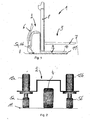
- FIG. 1 is designed as a tiller-guided high-lift pallet truck 1 illustrated, comprising a drive part 2 and a load part 3.
- the drive part 2 has with respect to the longitudinal axis of the truck 1, a centrally arranged drive wheel 4 and two laterally arranged casters 5a, 5b.
- the drive wheel 4 can be steered by means of a drawbar 6.
- the load part 3 comprises support arms 7, which are arranged on a mast 8 up and down movable.
- the load part 3 further comprises two wheel arms 9, in each of which a load roller 10 designed as a single roller or tandem roller is mounted.
- the truck 1 is thus supported by means of the drive wheel 4, the castors 5a, 5b and the load rollers 10 on a roadway 11 from.
- FIG. 2 shows the schematic structure of the drive part 2 of the truck 1 according to the FIG. 1 ,
- the steerable drive wheel 4 is centered to the longitudinal axis of the Fork mounted in a manner not shown on the drive part 2.
- On both sides of the drive wheel 4 is spaced from the longitudinal axis of the truck each have a pivot roller 5a, 5b attached to the drive part 2.
- the swivel caster 5a, 5b is in each case supported on the roadway 11 by means of a spring-damper device 12a, 12b.
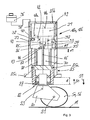
- FIG. 3 is the pivot roller 5a, 5b with a spring-damper device 12a, 12b shown in longitudinal section.
- the pivot roller 5a, 5b is rotatably mounted in a suspension 20 about a horizontal axis 21.
- the suspension 20 is mounted by means of a bearing 22, in particular a roller bearing, rotatably about a vertical axis 23 in a piston-shaped structural unit 24.
- the piston-shaped structural unit 24 is longitudinally displaceably mounted in a cylindrical component 25 of the spring-damper device 12a, 12b in the direction of the vertical axis 23.
- the cylindrical member 25 consists of a main body 25a, which is provided in the lower region with a flange 25c for attachment to the drive part 2, and a lid 25b, which is connected in a manner not shown with the main body 25a.
- the main body 25a and the cover 25b are provided at the mutually facing region, each with a flange formed by a bore heel, between the flanges a component 26 is arranged and fixed by the connection of the lid 25b with the main body 25a.
- a first space 30 is formed, in which a pivot roller 5a, 5b acting spring 27 is arranged.
- a further spring 28 is arranged, which is spaced from the component 26 and can be brought into operative connection with the swivel caster 5a, 5b starting from a predetermined spring deflection d1.
- the cover 25b and the component 26 delimit a compensation chamber 31, which is connected to the first space 30 via a throttling device 32 designed as a throttle and a blocking valve device 33 which opens as a first chamber 30 and is designed as a spring-loaded check valve.
- the throttle device 32 is in this case arranged in a guided from the compensation chamber 31 to the first space 30 connecting line 34, which in the device 26th is trained.
- the check valve device 33 is arranged in a further arranged in the component 26 connecting channel 35, which connects the compensation chamber 31 with the first space 30, the check valve device 33 is arranged.
- the compensation chamber 31 is further connected to a container 36 in connection.
- an annular groove 37 is formed on the component 26, which communicates with a channel formed in the cover 25 b 38 in connection, which is connected to the container 36.
- a connecting groove 39 connecting the annular groove 37 with the compensation chamber 31 is formed, in which a check valve designed as a spring-loaded check valve, which opens in the direction of the compensation chamber 31, is arranged.
- a second space 41 is formed, which is formed by a communicating with the compensation chamber 31 bore-shaped recess 42.
- a connecting channel 43 is further arranged, which is guided from the bore end of the recess 42 to the first space 30.
- this connection channel 43 designed as a throttle throttle device 44 is arranged.
- a damping piston 45 is arranged, which is connected via a guided in the component 26 piston rod 46 with the piston-shaped member 24 and thus the pivot roller 5a, 5b. Between the bore-shaped recess 42 and the damping piston 45, an annular gap is formed, which forms a second chamber 41 with the compensation chamber 31 connecting throttle device 47.
- the first space 30 and the second space 41 are completely filled with pressure medium, for example oil.
- the compensation chamber 31 is filled with pressure medium up to the level 48a.
- the compensation chamber 31 can also be brought under a gas bias.
- a channel 49 communicating with the compensation chamber 31 is provided in the cover 25a.
- the supporting force of the castor 5 a, 5 b is constant in accordance with the predetermined for the truck, by means of the springs 27, 28 and the gas pressure in the expansion chamber 31 adjustable deflection d.
- the compression speed of the castor 5a, 5b is attenuated and avoided multiple overshoot until reaching a state of equilibrium between the supporting force and the Radaufstandskraft, resulting in a controlled deflection behavior of the castor 5a, 5b results.
- a small roll angle about the vehicle longitudinal axis can be achieved with a high driving stability of the industrial truck, in particular during cornering of the industrial truck, by means of a slight deflection of the outside swivel castor.
- the check valve 40 can in this case automatically pressure fluid from the reservoir 36 in the expansion chamber 31 to compensate for the leakage.
Landscapes
- Engineering & Computer Science (AREA)
- Transportation (AREA)
- Structural Engineering (AREA)
- Mechanical Engineering (AREA)
- Civil Engineering (AREA)
- Life Sciences & Earth Sciences (AREA)
- Geology (AREA)
- Chemical & Material Sciences (AREA)
- Combustion & Propulsion (AREA)
- Vehicle Body Suspensions (AREA)
- Vibration Prevention Devices (AREA)
- Forklifts And Lifting Vehicles (AREA)
Claims (20)
- Chariot de manutention (1), en particulier chariot élévateur à fourche, comprenant une partie d'entraînement (2) et une partie de charge (3), au moins deux galets de charge (10) étant disposés dans la région de la partie de charge (3), et au moins une roue d'entraînement dirigeable (4) et au moins un galet pivotant (5a ; 5b) étant disposés dans la région de la partie d'entraînement (2), lequel galet pivotant est disposé de manière déplaçable verticalement et de manière à pouvoir tourner autour d'un axe vertical (23), et est supporté au moyen d'un dispositif ressort-amortisseur (12a ; 12b), caractérisé en ce que le dispositif ressort-amortisseur (12a ; 12b) comprend un moyen d'amortissement hydraulique agissant lors d'un débattement et lors d'une compression du galet pivotant (5a ; 5b), et le dispositif ressort-amortisseur (12a ; 12b) présente une courbe caractéristique de ressort progressive avec une force d'appui du galet pivotant (5a ; 5b) augmentant progressivement lors de la compression du galet pivotant (5a ; 5b) et avec une force d'appui du galet pivotant (5a ; 5b) diminuant progressivement lors du débattement du galet pivotant (5a ; 5b).
- Chariot de manutention selon la revendication 1, caractérisé en ce que le moyen d'amortissement est formé par au moins un dispositif d'étranglement (32 ; 44) agissant lors de la compression et par au moins un dispositif d'étranglement (44 ; 47) agissant lors du débattement.
- Chariot de manutention selon la revendication 1 ou 2, caractérisé en ce que le dispositif ressort-amortisseur (12a ; 12b) comprend un premier espace rempli d'huile (30), dont le volume est dépendant de la compression ou du débattement du galet pivotant (5a ; 5b) et qui est en liaison avec un espace de compensation (31) au moyen d'un dispositif d'étranglement (32), et comprend un deuxième espace rempli d'huile (41), dont le volume est dépendant de la compression ou du débattement du galet pivotant (5a ; 5b) et qui est en liaison avec le premier espace (30) au moyen d'un dispositif d'étranglement (44) et/ou avec l'espace de compensation (31) au moyen d'un dispositif d'étranglement (47).
- Chariot de manutention selon la revendication 3, caractérisé en ce que le premier espace (30) est en liaison avec l'espace de compensation (31) par le biais d'un dispositif de soupape d'arrêt (33) s'ouvrant en direction du premier espace (30), en particulier par le biais d'une soupape anti-retour.
- Chariot de manutention selon la revendication 3 ou 4, caractérisé en ce qu'un piston d'amortissement (45) en liaison fonctionnelle avec le galet pivotant (5a ; 5b) est disposé dans le deuxième espace (41).
- Chariot de manutention selon l'une quelconque des revendications 3 à 5, caractérisé en ce que l'espace de compensation (31) peut être amené à présenter une précontrainte de gaz.
- Chariot de manutention selon l'une quelconque des revendications 3 à 6, caractérisé en ce qu'un ressort (27), en liaison fonctionnelle avec le galet pivotant (5a ; 5b), du dispositif ressort-amortisseur (12a ; 12b) est disposé dans le premier espace rempli d'huile (30).
- Chariot de manutention selon l'une quelconque des revendications 1 à 7, caractérisé en ce qu'un ressort supplémentaire (28) est prévu, lequel peut être amené en liaison fonctionnelle avec le galet pivotant (5a ; 5b) à partir d'une compression prédéfinie (d1).
- Chariot de manutention selon l'une quelconque des revendications 3 à 7 en association avec la revendication 8, caractérisé en ce que le ressort supplémentaire (28) est disposé dans le premier espace rempli d'huile (30).
- Chariot de manutention selon l'une quelconque des revendications 3 à 9, caractérisé en ce que l'espace de compensation (31) est en liaison avec un récipient (36) par le biais d'une soupape d'arrêt (40) s'ouvrant en direction de l'espace de compensation (31), en particulier par le biais d'une soupape anti-retour.
- Chariot de manutention selon l'une quelconque des revendications 3 à 10, caractérisé en ce que le galet pivotant (5a ; 5b) est en liaison avec une unité structurale en forme de piston (24) qui est montée de manière déplaçable longitudinalement dans une partie structurale en forme de cylindre (25) dans laquelle le premier espace (30), le deuxième espace (41) et l'espace de compensation (31) sont réalisés.
- Chariot de manutention selon la revendication 11, caractérisé en ce qu'un élément structural (26) délimitant le premier espace (30) et l'espace de compensation (31) est disposé dans la partie structurale en forme de cylindre (25), dans lequel élément structural est réalisé le deuxième espace (41).
- Chariot de manutention selon la revendication 12, caractérisé en ce que le dispositif d'étranglement (32) reliant le premier espace (30) à l'espace de compensation (31) et/ou le dispositif d'étranglement (47) reliant le deuxième espace (41) à l'espace de compensation (31) et/ou le dispositif d'étranglement (44) reliant le deuxième espace (41) au premier espace (31) et/ou le dispositif de soupape d'arrêt (33) reliant le premier espace (30) à l'espace de compensation (31) et/ou la soupape d'arrêt (40) reliant l'espace de compensation (31) au récipient (36) sont disposés dans l'élément structural (26).
- Chariot de manutention selon la revendication 12 ou 13, caractérisé en ce que la partie structurale en forme de cylindre (25) comprend un corps de base (25a) délimitant le premier espace (30) et un couvercle (25b) délimitant l'espace de compensation (31), lequel couvercle peut être relié au corps de base (25a), l'élément structural (26) étant disposé et fixé entre le corps de base (25a) et le couvercle (25b).
- Chariot de manutention selon la revendication 13 ou 14, caractérisé en ce qu'un canal de liaison (34) reliant l'espace de compensation (31) au premier espace (30) est réalisé dans l'élément structural (26), dans lequel canal de liaison est disposé le dispositif d'étranglement (32), en particulier un étranglement.
- Chariot de manutention selon l'une quelconque des revendications 13 à 15, caractérisé en ce qu'un canal de liaison (35) reliant l'espace de compensation (31) au premier espace (30) est réalisé dans l'élément structural (26), dans lequel canal de liaison est disposé le dispositif de soupape d'arrêt (33), en particulier une soupape anti-retour.
- Chariot de manutention selon l'une quelconque des revendications 13 à 16, caractérisé en ce qu'un canal de liaison (43) reliant le deuxième espace (41) au premier espace (31) est réalisé dans l'élément structural (26), dans lequel canal de liaison est disposé le dispositif d'étranglement (44), en particulier un étranglement.
- Chariot de manutention selon l'une quelconque des revendications 13 à 17, caractérisé en ce que le deuxième espace (41) est formé par un évidement en forme d'alésage (42) de l'élément structural (26) en liaison avec l'espace de compensation (31), dans lequel évidement est disposé le piston d'amortissement (45), le dispositif d'étranglement (47) reliant le deuxième espace (41) à l'espace de compensation (31) étant formé par un interstice annulaire entre le piston d'amortissement (45) et l'évidement (42).
- Chariot de manutention selon l'une quelconque des revendications 13 à 18, caractérisé en ce qu'une rainure annulaire (37) est réalisée dans l'élément structural (26), laquelle est en liaison avec un canal (38) réalisé dans le couvercle (25b), lequel canal peut être raccordé au récipient (36), un canal de liaison (39) menant de la rainure annulaire (37) à l'espace de compensation (31) étant réalisé dans l'élément structural (26), dans lequel canal de liaison est disposée la soupape d'arrêt (40), en particulier une soupape anti-retour.
- Chariot de manutention selon l'une quelconque des revendications 5 à 19, caractérisé en ce que le piston d'amortissement (45) est en liaison avec le galet pivotant (5a ; 5b), en particulier avec l'unité structurale en forme de piston (24), au moyen d'une tige de piston (46).
Applications Claiming Priority (2)
| Application Number | Priority Date | Filing Date | Title |
|---|---|---|---|
| DE200410019072 DE102004019072A1 (de) | 2004-04-20 | 2004-04-20 | Flurförderzeug, insbesondere Gabelhubwagen |
| DE102004019072 | 2004-04-20 |
Publications (3)
| Publication Number | Publication Date |
|---|---|
| EP1588979A2 EP1588979A2 (fr) | 2005-10-26 |
| EP1588979A3 EP1588979A3 (fr) | 2011-11-30 |
| EP1588979B1 true EP1588979B1 (fr) | 2014-11-26 |
Family
ID=34935037
Family Applications (1)
| Application Number | Title | Priority Date | Filing Date |
|---|---|---|---|
| EP20050007977 Expired - Lifetime EP1588979B1 (fr) | 2004-04-20 | 2005-04-12 | Chariot de manutention, en particulier chariot élévateur à fourche |
Country Status (3)
| Country | Link |
|---|---|
| EP (1) | EP1588979B1 (fr) |
| CN (1) | CN1689957B (fr) |
| DE (1) | DE102004019072A1 (fr) |
Cited By (1)
| Publication number | Priority date | Publication date | Assignee | Title |
|---|---|---|---|---|
| CN106986286A (zh) * | 2017-05-23 | 2017-07-28 | 安徽宇锋仓储设备有限公司 | 叉车货叉 |
Families Citing this family (14)
| Publication number | Priority date | Publication date | Assignee | Title |
|---|---|---|---|---|
| DE102008030553B4 (de) * | 2008-06-27 | 2025-05-22 | Kion Warehouse Systems Gmbh | Flurförderzeug, insbesondere Hochregalflurförderzeug |
| CN101747228B (zh) * | 2008-11-28 | 2013-06-26 | 中国石油化工股份有限公司 | 一种酮或醛的氨肟化反应 |
| US9403667B2 (en) | 2011-03-18 | 2016-08-02 | The Raymond Corporation | Dynamic vibration control systems and methods for industrial lift trucks |
| US8731785B2 (en) | 2011-03-18 | 2014-05-20 | The Raymond Corporation | Dynamic stability control systems and methods for industrial lift trucks |
| CN102442623B (zh) * | 2011-12-17 | 2016-04-13 | 苏州先锋物流装备科技有限公司 | 一种堆垛车用可调节式平衡轮 |
| CN102515057A (zh) * | 2011-12-19 | 2012-06-27 | 苏州先锋物流装备科技有限公司 | 一种电动托盘搬运车 |
| CN102515061A (zh) * | 2011-12-19 | 2012-06-27 | 苏州先锋物流装备科技有限公司 | 一种减震堆垛车 |
| US8763990B2 (en) * | 2012-03-20 | 2014-07-01 | The Raymond Corporation | Turn stability systems and methods for lift trucks |
| US9302893B2 (en) | 2013-02-07 | 2016-04-05 | The Raymond Corporation | Vibration control systems and methods for industrial lift trucks |
| US9002557B2 (en) | 2013-03-14 | 2015-04-07 | The Raymond Corporation | Systems and methods for maintaining an industrial lift truck within defined bounds |
| US10315900B2 (en) | 2014-04-01 | 2019-06-11 | The Raymond Corporation | Caster wheel with constant force mechanism |
| US9593003B2 (en) * | 2014-04-01 | 2017-03-14 | The Raymond Corporation | Caster wheel with constant force mechanism |
| EP3459814B1 (fr) | 2017-09-25 | 2022-04-13 | Mitsubishi Logisnext Europe AB | Dispositif de roue de support de stabilisation et chariot de manutention comprenant un tel dispositif de roue de support |
| CN112279155B (zh) * | 2020-10-20 | 2022-07-19 | 苏州三鼎升降机有限公司 | 一种用于搬运铠装移开式开关柜功能车的液压升降车 |
Family Cites Families (9)
| Publication number | Priority date | Publication date | Assignee | Title |
|---|---|---|---|---|
| US5845896A (en) * | 1995-09-08 | 1998-12-08 | Riad; Fawzy | Counter balanced suspension |
| DE3106027C2 (de) * | 1981-02-19 | 1985-11-28 | Jungheinrich Unternehmensverwaltung Kg, 2000 Hamburg | Hublader mit einem höhenausgleichbaren Radnabenantrieb |
| DE3402495A1 (de) * | 1984-01-25 | 1985-07-25 | Steinbock Gmbh, 8052 Moosburg | Deichselgelenktes foerdergeraet |
| DE4432620C2 (de) * | 1994-09-14 | 1996-08-01 | Jungheinrich Ag | Flurförderzeug |
| TW445224B (en) * | 1997-03-25 | 2001-07-11 | Toyoda Automatic Loom Works | Axle controller for industrial vehicles |
| SE509022C2 (sv) * | 1997-11-28 | 1998-11-30 | Bt Ind Ab | Anordning vid stödhjul för truck |
| DE19753412C2 (de) * | 1997-12-02 | 2001-03-22 | Jungheinrich Ag | Gabelhubwagen mit verstellbarer Stützrolle |
| JP2000062428A (ja) * | 1998-08-21 | 2000-02-29 | Toyota Autom Loom Works Ltd | 産業車両の車体揺動制御装置 |
| DE10033801A1 (de) * | 2000-07-12 | 2002-01-24 | Fiat Om Carrelli Elevatori | Flurförderzug |
-
2004
- 2004-04-20 DE DE200410019072 patent/DE102004019072A1/de not_active Withdrawn
-
2005
- 2005-04-12 EP EP20050007977 patent/EP1588979B1/fr not_active Expired - Lifetime
- 2005-04-20 CN CN 200510067264 patent/CN1689957B/zh not_active Expired - Lifetime
Cited By (1)
| Publication number | Priority date | Publication date | Assignee | Title |
|---|---|---|---|---|
| CN106986286A (zh) * | 2017-05-23 | 2017-07-28 | 安徽宇锋仓储设备有限公司 | 叉车货叉 |
Also Published As
| Publication number | Publication date |
|---|---|
| DE102004019072A1 (de) | 2005-11-17 |
| EP1588979A3 (fr) | 2011-11-30 |
| CN1689957A (zh) | 2005-11-02 |
| CN1689957B (zh) | 2011-11-23 |
| EP1588979A2 (fr) | 2005-10-26 |
Similar Documents
| Publication | Publication Date | Title |
|---|---|---|
| EP1588979B1 (fr) | Chariot de manutention, en particulier chariot élévateur à fourche | |
| EP1117548B1 (fr) | Systeme de suspension hydropneumatique | |
| DE2411796C3 (de) | Druckmittelfederung mit aktiver Stabilisierung und Höhenregelung für Fahrzeuge | |
| DE69531448T2 (de) | Hydraulische aufhängung mit unabhängiger regelung von nick- und rollbewegung | |
| EP2804774B1 (fr) | Dispositif de suspension de cabine de conduite à stabilisation de roulis | |
| DE69931859T2 (de) | Fahrzeugaufhängungsvorrichtung | |
| DE69003926T2 (de) | Fahrzeug mit Achsaufhängungsvorrichtung mit Gasfedern und Regelsystem dafür. | |
| EP0512550B1 (fr) | Suspension d'essieu directeur à ressort | |
| EP3015296A2 (fr) | Suspension de roue permettant l'inclinaison pour vehicules | |
| DE2715247C2 (de) | Fahrgestellkonstruktion für ein geländegängiges Fahrzeug mit Knicksteuerung | |
| DE102020105378A1 (de) | Lenkbare Einzelradaufhängung mit zusätzlichem Träger | |
| DE19753412C2 (de) | Gabelhubwagen mit verstellbarer Stützrolle | |
| DE10022400B4 (de) | Gabelhubwagen mit einem Fünfradfahrwerk | |
| DE4227954C2 (de) | Dreirädriges Flurförderzeug | |
| EP3519286B1 (fr) | Motocyclette avec dispositif fluide pour baisser | |
| WO2004016967A1 (fr) | Soupape a piston et/ou soupape d'admission commandable destinee a un amortisseur d'oscillations | |
| DE4205150A1 (de) | Lenkrolle fuer vier- oder mehrraedrige fahrzeuge, insbesondere flurfoerderzeuge | |
| DE4004204A1 (de) | Hydropneumatisches federungssystem mit kippausgleich | |
| DE1901470A1 (de) | Aufhaengung,insbesondere Rad-Aufhaengung,fuer Fahrzeuge | |
| EP1477343A2 (fr) | Système de suspension pour véhicule avec hauteur de châssis variable | |
| DE102020105379A1 (de) | Lenkbare Einzelradaufhängung mit Tragvorrichtung | |
| DE102020105380A1 (de) | Lenkbare Einzelradaufhängung mit Federeinrichtung | |
| DE19912898C1 (de) | Verspannungsregleranordnung für ein Fahrzeug | |
| EP1743786A2 (fr) | Suspension hydropneumatique | |
| DE69809847T2 (de) | Steuerungseinrichtung und hydraulischer Zylinder für eine schwenkbare Nutzfahrzeugachse |
Legal Events
| Date | Code | Title | Description |
|---|---|---|---|
| PUAI | Public reference made under article 153(3) epc to a published international application that has entered the european phase |
Free format text: ORIGINAL CODE: 0009012 |
|
| AK | Designated contracting states |
Kind code of ref document: A2 Designated state(s): AT BE BG CH CY CZ DE DK EE ES FI FR GB GR HU IE IS IT LI LT LU MC NL PL PT RO SE SI SK TR |
|
| AX | Request for extension of the european patent |
Extension state: AL BA HR LV MK YU |
|
| PUAL | Search report despatched |
Free format text: ORIGINAL CODE: 0009013 |
|
| AK | Designated contracting states |
Kind code of ref document: A3 Designated state(s): AT BE BG CH CY CZ DE DK EE ES FI FR GB GR HU IE IS IT LI LT LU MC NL PL PT RO SE SI SK TR |
|
| AX | Request for extension of the european patent |
Extension state: AL BA HR LV MK YU |
|
| RIC1 | Information provided on ipc code assigned before grant |
Ipc: B60G 17/005 20060101ALI20111027BHEP Ipc: B66F 9/075 20060101AFI20111027BHEP |
|
| 17P | Request for examination filed |
Effective date: 20120314 |
|
| 17Q | First examination report despatched |
Effective date: 20120403 |
|
| AKX | Designation fees paid |
Designated state(s): AT BE BG CH CY CZ DE DK EE ES FI FR GB GR HU IE IS IT LI LT LU MC NL PL PT RO SE SI SK TR |
|
| GRAP | Despatch of communication of intention to grant a patent |
Free format text: ORIGINAL CODE: EPIDOSNIGR1 |
|
| INTG | Intention to grant announced |
Effective date: 20140813 |
|
| GRAS | Grant fee paid |
Free format text: ORIGINAL CODE: EPIDOSNIGR3 |
|
| GRAA | (expected) grant |
Free format text: ORIGINAL CODE: 0009210 |
|
| AK | Designated contracting states |
Kind code of ref document: B1 Designated state(s): AT BE BG CH CY CZ DE DK EE ES FI FR GB GR HU IE IS IT LI LT LU MC NL PL PT RO SE SI SK TR |
|
| REG | Reference to a national code |
Ref country code: GB Ref legal event code: FG4D Free format text: NOT ENGLISH |
|
| REG | Reference to a national code |
Ref country code: CH Ref legal event code: EP |
|
| REG | Reference to a national code |
Ref country code: AT Ref legal event code: REF Ref document number: 698038 Country of ref document: AT Kind code of ref document: T Effective date: 20141215 |
|
| REG | Reference to a national code |
Ref country code: IE Ref legal event code: FG4D Free format text: LANGUAGE OF EP DOCUMENT: GERMAN |
|
| REG | Reference to a national code |
Ref country code: DE Ref legal event code: R096 Ref document number: 502005014603 Country of ref document: DE Effective date: 20150108 |
|
| REG | Reference to a national code |
Ref country code: SE Ref legal event code: TRGR |
|
| REG | Reference to a national code |
Ref country code: NL Ref legal event code: VDEP Effective date: 20141126 |
|
| REG | Reference to a national code |
Ref country code: LT Ref legal event code: MG4D |
|
| PG25 | Lapsed in a contracting state [announced via postgrant information from national office to epo] |
Ref country code: NL Free format text: LAPSE BECAUSE OF FAILURE TO SUBMIT A TRANSLATION OF THE DESCRIPTION OR TO PAY THE FEE WITHIN THE PRESCRIBED TIME-LIMIT Effective date: 20141126 Ref country code: ES Free format text: LAPSE BECAUSE OF FAILURE TO SUBMIT A TRANSLATION OF THE DESCRIPTION OR TO PAY THE FEE WITHIN THE PRESCRIBED TIME-LIMIT Effective date: 20141126 Ref country code: FI Free format text: LAPSE BECAUSE OF FAILURE TO SUBMIT A TRANSLATION OF THE DESCRIPTION OR TO PAY THE FEE WITHIN THE PRESCRIBED TIME-LIMIT Effective date: 20141126 Ref country code: LT Free format text: LAPSE BECAUSE OF FAILURE TO SUBMIT A TRANSLATION OF THE DESCRIPTION OR TO PAY THE FEE WITHIN THE PRESCRIBED TIME-LIMIT Effective date: 20141126 Ref country code: IS Free format text: LAPSE BECAUSE OF FAILURE TO SUBMIT A TRANSLATION OF THE DESCRIPTION OR TO PAY THE FEE WITHIN THE PRESCRIBED TIME-LIMIT Effective date: 20150326 Ref country code: PT Free format text: LAPSE BECAUSE OF FAILURE TO SUBMIT A TRANSLATION OF THE DESCRIPTION OR TO PAY THE FEE WITHIN THE PRESCRIBED TIME-LIMIT Effective date: 20150326 |
|
| PG25 | Lapsed in a contracting state [announced via postgrant information from national office to epo] |
Ref country code: GR Free format text: LAPSE BECAUSE OF FAILURE TO SUBMIT A TRANSLATION OF THE DESCRIPTION OR TO PAY THE FEE WITHIN THE PRESCRIBED TIME-LIMIT Effective date: 20150227 Ref country code: CY Free format text: LAPSE BECAUSE OF FAILURE TO SUBMIT A TRANSLATION OF THE DESCRIPTION OR TO PAY THE FEE WITHIN THE PRESCRIBED TIME-LIMIT Effective date: 20141126 |
|
| PG25 | Lapsed in a contracting state [announced via postgrant information from national office to epo] |
Ref country code: EE Free format text: LAPSE BECAUSE OF FAILURE TO SUBMIT A TRANSLATION OF THE DESCRIPTION OR TO PAY THE FEE WITHIN THE PRESCRIBED TIME-LIMIT Effective date: 20141126 Ref country code: DK Free format text: LAPSE BECAUSE OF FAILURE TO SUBMIT A TRANSLATION OF THE DESCRIPTION OR TO PAY THE FEE WITHIN THE PRESCRIBED TIME-LIMIT Effective date: 20141126 Ref country code: CZ Free format text: LAPSE BECAUSE OF FAILURE TO SUBMIT A TRANSLATION OF THE DESCRIPTION OR TO PAY THE FEE WITHIN THE PRESCRIBED TIME-LIMIT Effective date: 20141126 Ref country code: RO Free format text: LAPSE BECAUSE OF FAILURE TO SUBMIT A TRANSLATION OF THE DESCRIPTION OR TO PAY THE FEE WITHIN THE PRESCRIBED TIME-LIMIT Effective date: 20141126 Ref country code: SK Free format text: LAPSE BECAUSE OF FAILURE TO SUBMIT A TRANSLATION OF THE DESCRIPTION OR TO PAY THE FEE WITHIN THE PRESCRIBED TIME-LIMIT Effective date: 20141126 |
|
| REG | Reference to a national code |
Ref country code: DE Ref legal event code: R097 Ref document number: 502005014603 Country of ref document: DE |
|
| PG25 | Lapsed in a contracting state [announced via postgrant information from national office to epo] |
Ref country code: PL Free format text: LAPSE BECAUSE OF FAILURE TO SUBMIT A TRANSLATION OF THE DESCRIPTION OR TO PAY THE FEE WITHIN THE PRESCRIBED TIME-LIMIT Effective date: 20141126 |
|
| PLBE | No opposition filed within time limit |
Free format text: ORIGINAL CODE: 0009261 |
|
| STAA | Information on the status of an ep patent application or granted ep patent |
Free format text: STATUS: NO OPPOSITION FILED WITHIN TIME LIMIT |
|
| 26N | No opposition filed |
Effective date: 20150827 |
|
| PG25 | Lapsed in a contracting state [announced via postgrant information from national office to epo] |
Ref country code: LU Free format text: LAPSE BECAUSE OF FAILURE TO SUBMIT A TRANSLATION OF THE DESCRIPTION OR TO PAY THE FEE WITHIN THE PRESCRIBED TIME-LIMIT Effective date: 20150412 Ref country code: MC Free format text: LAPSE BECAUSE OF FAILURE TO SUBMIT A TRANSLATION OF THE DESCRIPTION OR TO PAY THE FEE WITHIN THE PRESCRIBED TIME-LIMIT Effective date: 20141126 |
|
| REG | Reference to a national code |
Ref country code: CH Ref legal event code: PL |
|
| GBPC | Gb: european patent ceased through non-payment of renewal fee |
Effective date: 20150412 |
|
| REG | Reference to a national code |
Ref country code: IE Ref legal event code: MM4A |
|
| PG25 | Lapsed in a contracting state [announced via postgrant information from national office to epo] |
Ref country code: GB Free format text: LAPSE BECAUSE OF NON-PAYMENT OF DUE FEES Effective date: 20150412 Ref country code: CH Free format text: LAPSE BECAUSE OF NON-PAYMENT OF DUE FEES Effective date: 20150430 Ref country code: LI Free format text: LAPSE BECAUSE OF NON-PAYMENT OF DUE FEES Effective date: 20150430 |
|
| PG25 | Lapsed in a contracting state [announced via postgrant information from national office to epo] |
Ref country code: SI Free format text: LAPSE BECAUSE OF FAILURE TO SUBMIT A TRANSLATION OF THE DESCRIPTION OR TO PAY THE FEE WITHIN THE PRESCRIBED TIME-LIMIT Effective date: 20141126 |
|
| REG | Reference to a national code |
Ref country code: FR Ref legal event code: PLFP Year of fee payment: 12 |
|
| PG25 | Lapsed in a contracting state [announced via postgrant information from national office to epo] |
Ref country code: IE Free format text: LAPSE BECAUSE OF NON-PAYMENT OF DUE FEES Effective date: 20150412 |
|
| REG | Reference to a national code |
Ref country code: AT Ref legal event code: MM01 Ref document number: 698038 Country of ref document: AT Kind code of ref document: T Effective date: 20150412 |
|
| PG25 | Lapsed in a contracting state [announced via postgrant information from national office to epo] |
Ref country code: AT Free format text: LAPSE BECAUSE OF NON-PAYMENT OF DUE FEES Effective date: 20150412 |
|
| REG | Reference to a national code |
Ref country code: DE Ref legal event code: R082 Ref document number: 502005014603 Country of ref document: DE Representative=s name: PATENTSHIP PATENTANWALTSGESELLSCHAFT MBH, DE |
|
| REG | Reference to a national code |
Ref country code: DE Ref legal event code: R082 Ref document number: 502005014603 Country of ref document: DE Representative=s name: PATENTSHIP PATENTANWALTSGESELLSCHAFT MBH, DE |
|
| REG | Reference to a national code |
Ref country code: FR Ref legal event code: PLFP Year of fee payment: 13 |
|
| PG25 | Lapsed in a contracting state [announced via postgrant information from national office to epo] |
Ref country code: HU Free format text: LAPSE BECAUSE OF FAILURE TO SUBMIT A TRANSLATION OF THE DESCRIPTION OR TO PAY THE FEE WITHIN THE PRESCRIBED TIME-LIMIT; INVALID AB INITIO Effective date: 20050412 Ref country code: BG Free format text: LAPSE BECAUSE OF FAILURE TO SUBMIT A TRANSLATION OF THE DESCRIPTION OR TO PAY THE FEE WITHIN THE PRESCRIBED TIME-LIMIT Effective date: 20141126 |
|
| PG25 | Lapsed in a contracting state [announced via postgrant information from national office to epo] |
Ref country code: BE Free format text: LAPSE BECAUSE OF NON-PAYMENT OF DUE FEES Effective date: 20150430 |
|
| PG25 | Lapsed in a contracting state [announced via postgrant information from national office to epo] |
Ref country code: TR Free format text: LAPSE BECAUSE OF FAILURE TO SUBMIT A TRANSLATION OF THE DESCRIPTION OR TO PAY THE FEE WITHIN THE PRESCRIBED TIME-LIMIT Effective date: 20141126 |
|
| REG | Reference to a national code |
Ref country code: FR Ref legal event code: PLFP Year of fee payment: 14 |
|
| PGFP | Annual fee paid to national office [announced via postgrant information from national office to epo] |
Ref country code: TR Payment date: 20180612 Year of fee payment: 15 |
|
| REG | Reference to a national code |
Ref country code: DE Ref legal event code: R082 Ref document number: 502005014603 Country of ref document: DE Representative=s name: PATENTSHIP PATENTANWALTSGESELLSCHAFT MBH, DE Ref country code: DE Ref legal event code: R081 Ref document number: 502005014603 Country of ref document: DE Owner name: STILL S.P.A., IT Free format text: FORMER OWNER: OM CARRELLI ELEVATORI S.P.A., LAINATE, IT |
|
| PG25 | Lapsed in a contracting state [announced via postgrant information from national office to epo] |
Ref country code: IT Free format text: LAPSE BECAUSE OF NON-PAYMENT OF DUE FEES Effective date: 20190412 |
|
| PGFP | Annual fee paid to national office [announced via postgrant information from national office to epo] |
Ref country code: DE Payment date: 20240418 Year of fee payment: 20 |
|
| PGFP | Annual fee paid to national office [announced via postgrant information from national office to epo] |
Ref country code: FR Payment date: 20240417 Year of fee payment: 20 |
|
| PGFP | Annual fee paid to national office [announced via postgrant information from national office to epo] |
Ref country code: SE Payment date: 20240423 Year of fee payment: 20 |
|
| REG | Reference to a national code |
Ref country code: DE Ref legal event code: R071 Ref document number: 502005014603 Country of ref document: DE |
|
| REG | Reference to a national code |
Ref country code: SE Ref legal event code: EUG |