EP1588979B1 - Industrial truck, in particular forklift truck - Google Patents
Industrial truck, in particular forklift truck Download PDFInfo
- Publication number
- EP1588979B1 EP1588979B1 EP20050007977 EP05007977A EP1588979B1 EP 1588979 B1 EP1588979 B1 EP 1588979B1 EP 20050007977 EP20050007977 EP 20050007977 EP 05007977 A EP05007977 A EP 05007977A EP 1588979 B1 EP1588979 B1 EP 1588979B1
- Authority
- EP
- European Patent Office
- Prior art keywords
- space
- industrial truck
- truck according
- equalizing
- pivot roller
- Prior art date
- Legal status (The legal status is an assumption and is not a legal conclusion. Google has not performed a legal analysis and makes no representation as to the accuracy of the status listed.)
- Expired - Lifetime
Links
Images
Classifications
-
- B—PERFORMING OPERATIONS; TRANSPORTING
- B60—VEHICLES IN GENERAL
- B60G—VEHICLE SUSPENSION ARRANGEMENTS
- B60G17/00—Resilient suspensions having means for adjusting the spring or vibration-damper characteristics, for regulating the distance between a supporting surface and a sprung part of vehicle or for locking suspension during use to meet varying vehicular or surface conditions, e.g. due to speed or load
- B60G17/005—Suspension locking arrangements
-
- B—PERFORMING OPERATIONS; TRANSPORTING
- B66—HOISTING; LIFTING; HAULING
- B66F—HOISTING, LIFTING, HAULING OR PUSHING, NOT OTHERWISE PROVIDED FOR, e.g. DEVICES WHICH APPLY A LIFTING OR PUSHING FORCE DIRECTLY TO THE SURFACE OF A LOAD
- B66F9/00—Devices for lifting or lowering bulky or heavy goods for loading or unloading purposes
- B66F9/06—Devices for lifting or lowering bulky or heavy goods for loading or unloading purposes movable, with their loads, on wheels or the like, e.g. fork-lift trucks
- B66F9/075—Constructional features or details
- B66F9/07572—Propulsion arrangements
-
- B—PERFORMING OPERATIONS; TRANSPORTING
- B66—HOISTING; LIFTING; HAULING
- B66F—HOISTING, LIFTING, HAULING OR PUSHING, NOT OTHERWISE PROVIDED FOR, e.g. DEVICES WHICH APPLY A LIFTING OR PUSHING FORCE DIRECTLY TO THE SURFACE OF A LOAD
- B66F9/00—Devices for lifting or lowering bulky or heavy goods for loading or unloading purposes
- B66F9/06—Devices for lifting or lowering bulky or heavy goods for loading or unloading purposes movable, with their loads, on wheels or the like, e.g. fork-lift trucks
- B66F9/075—Constructional features or details
- B66F9/07586—Suspension or mounting of wheels on chassis
-
- B—PERFORMING OPERATIONS; TRANSPORTING
- B60—VEHICLES IN GENERAL
- B60G—VEHICLE SUSPENSION ARRANGEMENTS
- B60G2300/00—Indexing codes relating to the type of vehicle
- B60G2300/02—Trucks; Load vehicles
- B60G2300/022—Fork lift trucks, Clark
Definitions
- the invention relates to an industrial truck, in particular pallet truck, with a drive part and a load part, wherein at least two load rollers and in the region of the drive part at least one steerable drive wheel and at least one caster are arranged, which are arranged rotatably and vertically movable about a vertical axis is and is supported by means of a spring-damper device.
- Such trucks are known for example as pedestrian-controlled pedestrian vehicles or as a truck with a driver's cab or a driver's seat.
- the load part of such a truck is supported by means of two load rollers on the road.
- the drive member is supported by the drive wheel, which is preferably rigidly attached to the truck on the Farbahn.
- at least one pivot roller is provided on the drive part, which is mounted vertically movable and rotatable on the drive part.
- the drive wheel is arranged laterally spaced from the vehicle longitudinal axis and on the opposite side a spaced from the vehicle longitudinal axis pivot roller is arranged.
- the drive wheel is mounted centrally on the drive part and two casters on the sides of the drive part spaced from the vehicle longitudinal axis are arranged.
- the casters are supported by means of a spring-damper device on the road, wherein the spring of the spring-damper device determines the counteracting Radaufstandskraft supporting force of the caster. Due to the suspension of the casters, the truck becomes a vibratory system, which is provided with a damping means for vibration damping, the spring-damper device.
- a generic truck is out of the DE 197 53 412 C2 known.
- the caster is mounted in a rocker pivotable about a horizontal axis, on which a coil spring attacks. From the spring deflection of the Radaufstandskraft counteracting supporting force of the caster is determined.
- hydraulic cylinder shock absorbers are provided, which are arranged laterally next to the support roller on the rocker. The cylinder shock absorbers act on a deflection of the castor. In a rebound of the castor, the cylinder shock absorbers develop no damping effect.
- the JP 2000-62428 A discloses an industrial truck with a sprung suspended drive wheel and a spring-mounted suspended castor.
- the caster is supported by a spring between two links.
- a hydraulic locking cylinder is arranged, with which the deflection of the caster can be blocked in order to increase the stability of the truck when cornering.
- the locking cylinder is designed as a double-acting hydraulic cylinder whose pressure chambers are connected to each other by means of two lines. By means of a valve, the connection of the two lines can be made to allow the movement of the castor, or the connection of the two lines are shut off to block the castor.
- a surge tank is connected via an opening in the direction of the lines check valve.
- the present invention has for its object to provide an industrial truck of the type mentioned, which has an improved stability.
- the spring-damper device has an effective at a rebound and at a deflection of the caster hydraulic damping means and the spring-damper means a progressive spring characteristic with a progressively increasing during compression of the caster roller support force of the caster and a progressively decreasing during rebound of the swivel castor supporting force of the castor.
- a progressive spring characteristic of the spring-damper device can be achieved with little effort a progressive rising with increasing deflection, the Radaufstandskraft counteracting supporting force of the caster, wherein during rebound of the caster, the supporting force disproportionately decreases and the support force increases disproportionately during compression of the caster.
- a high driving stability of the truck can be achieved by low roll angle, for example during cornering, and high transferable from the drive wheel braking and driving forces. This results in an overall improved stability and improved handling of the truck, whereby the maximum speed of the truck in the loaded and unloaded state can be raised in receipt of the necessary vehicle stability in all driving conditions.
- the damping means of at least one effective during compression throttle device and at least one effective during rebound throttle device is formed.
- throttling devices can be provided in a simple manner, a hydraulic damping means that allows damping during compression and rebound of the caster.
- the spring-damper device according to a preferred embodiment of the invention, a first oil-filled space whose volume is dependent on the deflection or rebound of the castor and which is connected by means of a throttle device with a compensation chamber, and a second oil-filled space, whose volume is dependent on the deflection or rebound of the castor and which is connected by means of a throttle device with the first space and / or by means of a throttle device with the compensation chamber.
- the first chamber communicates with the compensation chamber via a check valve device which opens in the direction of the first chamber, in particular a non-return valve.
- a check valve device which opens in the direction of the first chamber, in particular a non-return valve.
- a damping piston operatively connected to the pivoting roller is arranged in the second space, a volume of the second space, which is dependent on the deflection or rebound of the pivoting roller, can be achieved with little construction effort.
- a progressive spring characteristic and thus a progressive course of the supporting force of the castor can be achieved in a simple manner according to a preferred embodiment of the invention, when the expansion chamber can be brought under a gas bias.
- a gas bias By compressing the gas in the expansion chamber during compression of the castor can be achieved in a simple manner, a progressive spring force and thus supporting force of the castor.
- the spring-damper device can be easily adapted to different types of trucks.
- a further spring is provided which can be brought into operative connection with the castor from a predetermined deflection, a progressive support force can be achieved with little effort.
- the further spring is arranged in the first oil-filled space, resulting in a small space requirement.
- the expansion chamber according to a development of the invention via a direction to the expansion chamber opening check valve, in particular a check valve, is in communication with a container. Leaks in the first room, in the second room and in the compensation chamber, which lead to a drop in gas pressure below the ambient pressure at rebound of the caster, thereby automatically compensated, whereby the spring-damper device has a high reliability.
- the caster is connected to a piston-shaped structural unit, which is mounted longitudinally displaceably in a cylindrical component, in which the first space, the second space and the compensation space is formed. Due to this design of the spring-damper device as a cylindrical assembly, I result in a low construction cost and space requirements.
- a component defining the first space and the compensation space is arranged on the cylindrical component, in which the second space is formed.
- the first space and the compensation space as well as the second space can be formed with low construction costs in the cylindrical component.
- a simple construction of the cylindrical component results in this case, when the cylindrical member has a first space limiting body and a compensating space limiting lid, which is connectable to the base body, wherein between the base body and the lid, the component is arranged and fixed. The component can thereby be clamped in a simple manner between the base body and the lid.
- the throttling device and / or shut-off valve device connecting the first space to the equalization chamber can be formed in the component in a simple manner if, in accordance with an advantageous embodiment, a connecting channel connecting the equalization chamber with the first space is formed in the component, in which the throttling device, in particular one Throttle, is arranged and / or in the component a connecting space connecting the expansion chamber with the first space is formed, in which the Spemrentil worn, in particular a check valve, is arranged.
- a simple arrangement results if a connection channel connecting the second space to the first space is formed in the component, in which the throttle device, in particular a throttle, is arranged.
- the throttling device connecting the second space to the equalizing space can be provided in a simple manner if the second space is formed by a bore-shaped recess of the component in which the damping piston is arranged, which accommodates the second space with the equalizing space connecting throttle device is formed by an annular gap between the damping piston and the recess.
- the compound of the expansion chamber with the container can be produced with low construction costs, if formed in the device according to an expedient embodiment of the invention, an annular groove, which communicates with a channel formed in the lid, which is connectable to the container, wherein in the component is formed by a guided from the annular groove to the expansion chamber connecting channel, in which the check valve, in particular a check valve, is arranged.
- damping piston A simple connection of the damping piston with the castor is obtained if expediently the damping piston is connected by means of a piston rod, which is guided in the component, with the piston-shaped structural unit.
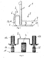
- FIG. 1 is designed as a tiller-guided high-lift pallet truck 1 illustrated, comprising a drive part 2 and a load part 3.
- the drive part 2 has with respect to the longitudinal axis of the truck 1, a centrally arranged drive wheel 4 and two laterally arranged casters 5a, 5b.
- the drive wheel 4 can be steered by means of a drawbar 6.
- the load part 3 comprises support arms 7, which are arranged on a mast 8 up and down movable.
- the load part 3 further comprises two wheel arms 9, in each of which a load roller 10 designed as a single roller or tandem roller is mounted.
- the truck 1 is thus supported by means of the drive wheel 4, the castors 5a, 5b and the load rollers 10 on a roadway 11 from.
- FIG. 2 shows the schematic structure of the drive part 2 of the truck 1 according to the FIG. 1 ,
- the steerable drive wheel 4 is centered to the longitudinal axis of the Fork mounted in a manner not shown on the drive part 2.
- On both sides of the drive wheel 4 is spaced from the longitudinal axis of the truck each have a pivot roller 5a, 5b attached to the drive part 2.
- the swivel caster 5a, 5b is in each case supported on the roadway 11 by means of a spring-damper device 12a, 12b.
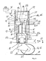
- FIG. 3 is the pivot roller 5a, 5b with a spring-damper device 12a, 12b shown in longitudinal section.
- the pivot roller 5a, 5b is rotatably mounted in a suspension 20 about a horizontal axis 21.
- the suspension 20 is mounted by means of a bearing 22, in particular a roller bearing, rotatably about a vertical axis 23 in a piston-shaped structural unit 24.
- the piston-shaped structural unit 24 is longitudinally displaceably mounted in a cylindrical component 25 of the spring-damper device 12a, 12b in the direction of the vertical axis 23.
- the cylindrical member 25 consists of a main body 25a, which is provided in the lower region with a flange 25c for attachment to the drive part 2, and a lid 25b, which is connected in a manner not shown with the main body 25a.
- the main body 25a and the cover 25b are provided at the mutually facing region, each with a flange formed by a bore heel, between the flanges a component 26 is arranged and fixed by the connection of the lid 25b with the main body 25a.
- a first space 30 is formed, in which a pivot roller 5a, 5b acting spring 27 is arranged.
- a further spring 28 is arranged, which is spaced from the component 26 and can be brought into operative connection with the swivel caster 5a, 5b starting from a predetermined spring deflection d1.
- the cover 25b and the component 26 delimit a compensation chamber 31, which is connected to the first space 30 via a throttling device 32 designed as a throttle and a blocking valve device 33 which opens as a first chamber 30 and is designed as a spring-loaded check valve.
- the throttle device 32 is in this case arranged in a guided from the compensation chamber 31 to the first space 30 connecting line 34, which in the device 26th is trained.
- the check valve device 33 is arranged in a further arranged in the component 26 connecting channel 35, which connects the compensation chamber 31 with the first space 30, the check valve device 33 is arranged.
- the compensation chamber 31 is further connected to a container 36 in connection.
- an annular groove 37 is formed on the component 26, which communicates with a channel formed in the cover 25 b 38 in connection, which is connected to the container 36.
- a connecting groove 39 connecting the annular groove 37 with the compensation chamber 31 is formed, in which a check valve designed as a spring-loaded check valve, which opens in the direction of the compensation chamber 31, is arranged.
- a second space 41 is formed, which is formed by a communicating with the compensation chamber 31 bore-shaped recess 42.
- a connecting channel 43 is further arranged, which is guided from the bore end of the recess 42 to the first space 30.
- this connection channel 43 designed as a throttle throttle device 44 is arranged.
- a damping piston 45 is arranged, which is connected via a guided in the component 26 piston rod 46 with the piston-shaped member 24 and thus the pivot roller 5a, 5b. Between the bore-shaped recess 42 and the damping piston 45, an annular gap is formed, which forms a second chamber 41 with the compensation chamber 31 connecting throttle device 47.
- the first space 30 and the second space 41 are completely filled with pressure medium, for example oil.
- the compensation chamber 31 is filled with pressure medium up to the level 48a.
- the compensation chamber 31 can also be brought under a gas bias.
- a channel 49 communicating with the compensation chamber 31 is provided in the cover 25a.
- the supporting force of the castor 5 a, 5 b is constant in accordance with the predetermined for the truck, by means of the springs 27, 28 and the gas pressure in the expansion chamber 31 adjustable deflection d.
- the compression speed of the castor 5a, 5b is attenuated and avoided multiple overshoot until reaching a state of equilibrium between the supporting force and the Radaufstandskraft, resulting in a controlled deflection behavior of the castor 5a, 5b results.
- a small roll angle about the vehicle longitudinal axis can be achieved with a high driving stability of the industrial truck, in particular during cornering of the industrial truck, by means of a slight deflection of the outside swivel castor.
- the check valve 40 can in this case automatically pressure fluid from the reservoir 36 in the expansion chamber 31 to compensate for the leakage.
Landscapes
- Engineering & Computer Science (AREA)
- Transportation (AREA)
- Structural Engineering (AREA)
- Mechanical Engineering (AREA)
- Civil Engineering (AREA)
- Life Sciences & Earth Sciences (AREA)
- Geology (AREA)
- Chemical & Material Sciences (AREA)
- Combustion & Propulsion (AREA)
- Vehicle Body Suspensions (AREA)
- Vibration Prevention Devices (AREA)
- Forklifts And Lifting Vehicles (AREA)
Description
Die Erfindung betrifft ein Flurförderzeug, insbesondere Gabelhubwagen, mit einem Antriebsteil und einem Lastteil, wobei im Bereich des Lastteils zumindest zwei Lastrollen und im Bereich des Antriebsteils zumindest ein lenkbares Antriebsrad und mindestens eine Schwenkrolle angeordnet sind, die um eine vertikale Achse drehbar und vertikal bewegbar angeordnet ist und mittels einer Feder-Dämpfer-Einrichtung abgestützt ist.The invention relates to an industrial truck, in particular pallet truck, with a drive part and a load part, wherein at least two load rollers and in the region of the drive part at least one steerable drive wheel and at least one caster are arranged, which are arranged rotatably and vertically movable about a vertical axis is and is supported by means of a spring-damper device.
Derartige Flurförderzeuge sind beispielsweise als deichselgeführte Mitgängerfahrzeuge oder als Hubwagen mit einem Fahrerstand bzw. einem Fahrersitz bekannt. Der Lastteil eines derartigen Flurförderzeugs ist mittels zweier Lastrollen auf der Fahrbahn abgestützt. Das Antriebsteil stützt sich mit dem Antriebsrad, das vorzugsweise starr am Flurförderzeug befestigt ist auf der Farbahn ab. Zur Stabilitätserhöhung ist am Antriebsteil zumindest eine Schwenkrolle vorgesehen, die vertikal bewegbar und drehbar am Antriebsteil gelagert ist. Hierbei sind Bauformen bekannt, bei denen das Antriebsrad seitlich im Abstand zur Fahrzeuglängsachse angeordnet ist und auf der gegenüberliegenden Seite eine von der Fahrzeuglängsachse beabstandete Schwenkrolle angeordnet ist. Neben derartigen Flurförderzeug mit einem Vierradfahrwerk sind ebenfalls Flurförderzeuge mit einem Fünfradfahrwerk bekannt, bei denen das Antriebsrad mittig am Antriebsteil befestigt ist und zwei Schwenkrollen an den Seiten des Antriebsteils beabstandet zur Fahrzeuglängsachse angeordnet sind.Such trucks are known for example as pedestrian-controlled pedestrian vehicles or as a truck with a driver's cab or a driver's seat. The load part of such a truck is supported by means of two load rollers on the road. The drive member is supported by the drive wheel, which is preferably rigidly attached to the truck on the Farbahn. To increase stability, at least one pivot roller is provided on the drive part, which is mounted vertically movable and rotatable on the drive part. In this case, designs are known in which the drive wheel is arranged laterally spaced from the vehicle longitudinal axis and on the opposite side a spaced from the vehicle longitudinal axis pivot roller is arranged. In addition to such trucks with a four-wheel drive trucks with a five-wheel drive are also known, in which the drive wheel is mounted centrally on the drive part and two casters on the sides of the drive part spaced from the vehicle longitudinal axis are arranged.
Die Schwenkrollen sind mittels einer Feder-Dämpfer-Einrichtung auf der Fahrbahn abgestützt, wobei die Feder der Feder-Dämpfer-Einrichtung die der Radaufstandskraft entgegenwirkende Abstützkraft der Schwenkrolle bestimmt. Durch die Federung der Schwenkrollen wird das Flurförderzeug zu einem schwingungsfähigen System, wobei zur Schwingungsdämpfung die Feder-Dämpfer-Einrichtung mit einem Dämpfungsmittel versehen ist.The casters are supported by means of a spring-damper device on the road, wherein the spring of the spring-damper device determines the counteracting Radaufstandskraft supporting force of the caster. Due to the suspension of the casters, the truck becomes a vibratory system, which is provided with a damping means for vibration damping, the spring-damper device.
Ein gattungsgemäßes Flurförderzeug ist aus der
Die
Der vorliegenden Erfindung liegt die Aufgabe zugrunde, ein Flurförderzeug der eingangs genannten Gattung zur Verfügung zu stellen, das eine verbesserte Stabilität aufweist.The present invention has for its object to provide an industrial truck of the type mentioned, which has an improved stability.
Diese Aufgabe wird erfindungsgemäß dadurch gelöst, dass die Feder-Dämpfer-Einrichtung ein bei einer Ausfederung und bei einer Einfederung der Schwenkrolle wirksames hydraulisches Dämpfungsmittel aufweist und die Feder-Dämpfer-Einrichtung eine progressive Federkennlinie mit einer beim Einfedern der Schwenkrolle progressiv ansteigenden Abstützkraft der Schwenkrolle und einer beim Ausfedern der Schwenkrolle progressiv abnehmenden Abstützkraft der Schwenkrolle aufweist. Mit einem derartigen Dämpfungsmittel kann die Ausfederungsgeschwindigkeit und die Einfederungsgeschwindigkeit der Schwenkrolle begrenzt werden, wodurch ein kontrolliertes Einfederverhalten und Ausfederverhalten der Schwenkrolle erzielt werden kann. Bei einer Kurvenfahrt oder einem Befahren einer unebenen Fahrbahnoberfläche können hierdurch die Überschwingvorgänge bei einer sich ändernden Radaufstandskraft verbessert werden und ein mehrfaches Überschwingen vermieden werden. Durch eine progressive Federkennlinie der Feder-Dämpfer-Einrichtung kann mit geringem Aufwand eine progressive mit zunehmender Einfederung ansteigende, der Radaufstandskraft entgegenwirkende Abstützkraft der Schwenkrolle erzielt werden, wobei beim Ausfedern der Schwenkrolle die Abstützkraft überproportional abnimmt und beim Einfedern der Schwenkrolle die Abstützkraft überproportional zunimmt. Durch ein derartiges Verhalten der Schwenkrolle kann eine hohe Fahrstabilität des Flurförderzeugs durch geringe Rollwinkel, beispielsweise während einer Kurvenfahrt, und hohe von dem Antriebsrad übertragbare Brems- und Antriebskräfte erzielt werden. Es ergibt sich somit insgesamt eine verbesserte Stabilität und ein verbessertes Fahrverhalten des Flurförderzeugs, wodurch die maximale Fahrgeschwindigkeit des Flurförderzeugs im beladenen und unbeladenen Zustand bei Erhalt der notwendigen Fahrzeugstabilität in allen Fahrzuständen angehoben werden kann.This object is achieved in that the spring-damper device has an effective at a rebound and at a deflection of the caster hydraulic damping means and the spring-damper means a progressive spring characteristic with a progressively increasing during compression of the caster roller support force of the caster and a progressively decreasing during rebound of the swivel castor supporting force of the castor. With such a damping means, the Ausfederungsgeschwindigkeit and the compression speed of the castor can be limited, whereby a controlled compression behavior and Ausfederverhalten the castor can be achieved. When cornering or driving on an uneven road surface, this can contribute to the overshoot a changing Radaufstandskraft be improved and a multiple overshoot can be avoided. By a progressive spring characteristic of the spring-damper device can be achieved with little effort a progressive rising with increasing deflection, the Radaufstandskraft counteracting supporting force of the caster, wherein during rebound of the caster, the supporting force disproportionately decreases and the support force increases disproportionately during compression of the caster. By such a behavior of the castor, a high driving stability of the truck can be achieved by low roll angle, for example during cornering, and high transferable from the drive wheel braking and driving forces. This results in an overall improved stability and improved handling of the truck, whereby the maximum speed of the truck in the loaded and unloaded state can be raised in receipt of the necessary vehicle stability in all driving conditions.
Gemäß einer bevorzugten Ausführungsform der Erfindung ist das Dämpfungsmittel von zumindest einer beim Einfedern wirksamen Drosseleinrichtung und zumindest einer beim Ausfedern wirksamen Drosseleinrichtung gebildet. Mit Drosseleinrichtungen kann auf einfache Weise ein hydraulisches Dämpfungsmittel zur Verfügung gestellt werden, das bei der Einfederung und bei der Ausfederung der Schwenkrolle eine Dämpfung ermöglicht.According to a preferred embodiment of the invention, the damping means of at least one effective during compression throttle device and at least one effective during rebound throttle device is formed. With throttling devices can be provided in a simple manner, a hydraulic damping means that allows damping during compression and rebound of the caster.
Zweckmäßigerweise weist die Feder-Dämpfer-Einrichtung gemäß einer bevorzugten Ausgestaltungsform der Erfindung einen ersten ölgefüllten Raum, dessen Volumen von der Einfederung bzw. Ausfederung der Schwenkrolle abhängig ist und der mittels einer Drosseleinrichtung mit einem Ausgleichsraum in Verbindung steht, und einen zweiten ölgefüllten Raum auf, dessen Volumen von der Einfederung bzw. Ausfederung der Schwenkrolle abhängig ist und der mittels einer Drosseleinrichtung mit dem ersten Raum und/oder mittels einer Drosseleinrichtung mit dem Ausgleichsraum in Verbindung steht. Mit einer derartigen Anordnung ist es auf einfache Weise möglich, einem beim Einfedern und einen beim Ausfedern wirksamen Raum zur Verfügung zu stellen und somit die Einfederungsgeschwindigkeit sowie die Ausfederungsgeschwindigkeit der Schwenkrolle über entsprechende Drosseleinrichtungen zu dämpfen, wodurch ein beim Einfedern sowie beim Ausfedern der Schwenkrolle wirksames Dämpfungsmittel erzielt wird.Conveniently, the spring-damper device according to a preferred embodiment of the invention, a first oil-filled space whose volume is dependent on the deflection or rebound of the castor and which is connected by means of a throttle device with a compensation chamber, and a second oil-filled space, whose volume is dependent on the deflection or rebound of the castor and which is connected by means of a throttle device with the first space and / or by means of a throttle device with the compensation chamber. With such an arrangement, it is easily possible to provide an effective during compression and rebound space and thus to dampen the compression speed and the Ausfederungsgeschwindigkeit the caster on respective throttling devices, whereby an effective during compression and rebound of the caster damping means is achieved.
Zweckmäßigerweise steht der erste Raum über eine in Richtung zum ersten Raum öffnende Sperrventileinrichtung, insbesondere ein Rückschlagventil, mit dem Ausgleichsraum in Verbindung. Hierdurch kann erzielt werden, dass beim Ausfedern Druckmittel über die geöffnete Sperrventileinrichtung vom Ausgleichsraum in den ersten Raum strömt und somit die Dämpfung der Ausfederungsgeschwindigkeit über die den zweiten Raum mit dem ersten Raum und/oder dem Ausgleichsraum verbindende Drosseleinrichtungen erfolgt.Conveniently, the first chamber communicates with the compensation chamber via a check valve device which opens in the direction of the first chamber, in particular a non-return valve. In this way, it can be achieved that, during rebounding, pressure medium flows via the opened shut-off valve device from the equalizing chamber into the first space and thus the damping of the rebounding speed takes place via the throttling devices connecting the second space to the first space and / or the equalizing space.
Sofern gemäß einer bevorzugten Ausgestaltungsform der Erfindung in dem zweiten Raum ein mit der Schwenkrolle in Wirkverbindung stehender Dämpfungskolben angeordnet ist, kann mit geringem Bauaufwand ein von der Einfederung bzw. Ausfederung der Schwenkrolle abhängiges Volumen des zweiten Raumes erzielt werden.If, according to a preferred embodiment of the invention, a damping piston operatively connected to the pivoting roller is arranged in the second space, a volume of the second space, which is dependent on the deflection or rebound of the pivoting roller, can be achieved with little construction effort.
Eine progressive Federkennlinie und somit ein progressiver Verlauf der Abstützkraft der Schwenkrolle kann gemäß einer bevorzugten Ausführungsform der Erfindung auf einfache Weise erzielt werden, wenn der Ausgleichsraum unter eine Gasvorspannung bringbar ist. Durch die Komprimierung des Gases in dem Ausgleichsraum beim Einfedern der Schwenkrolle kann auf einfache Weise eine progressive Federkraft und somit Abstützkraft der Schwenkrolle erzielt werden. Zudem kann durch Veränderung der Gasvorspannung die Feder-Dämpfer-Einrichtung auf einfache Weise an verschiedene Typen von Flurförderzeugen angepasst werden.A progressive spring characteristic and thus a progressive course of the supporting force of the castor can be achieved in a simple manner according to a preferred embodiment of the invention, when the expansion chamber can be brought under a gas bias. By compressing the gas in the expansion chamber during compression of the castor can be achieved in a simple manner, a progressive spring force and thus supporting force of the castor. In addition, by changing the gas bias the spring-damper device can be easily adapted to different types of trucks.
Zweckmäßigerweise ist in dem ersten ölgefüllten Raum eine mit der Schwenkrolle in Wirkverbindung stehende Feder der Feder-Dämpfer-Einrichtung angeordnet. Durch die Anordnung der die Schwenkrolle beaufschlagenden Feder in den ersten Raum ergibt sich ein geringer Bauraumbedarf.Conveniently, in the first oil-filled space with a standing in operative connection with the pivot roller spring of the spring-damper device is arranged. The arrangement of the spring acting on the caster in the first room results in a small space requirement.
Sofern gemäß einer bevorzugten Weiterbildung der Erfindung eine weitere Feder vorgesehen ist, die ab einer vorgegebenen Einfederung mit der Schwenkrolle in Wirkverbindung bringbar ist, kann mit geringem Aufwand eine progressive Abstützkraft erzielt werden.If, according to a preferred embodiment of the invention, a further spring is provided which can be brought into operative connection with the castor from a predetermined deflection, a progressive support force can be achieved with little effort.
Zweckmäßigerweise ist die weitere Feder in dem ersten ölgefüllten Raum angeordnet, wodurch sich ein geringer Bauraumbedarf ergibt.Conveniently, the further spring is arranged in the first oil-filled space, resulting in a small space requirement.
Besondere Vorteile ergeben sich, wenn der Ausgleichsraum gemäß einer Weiterbildung der Erfindung über ein in Richtung zum Ausgleichsraum öffnendes Sperrventil, insbesondere ein Rückschlagventil, mit einem Behälter in Verbindung steht. Leckagen im ersten Raum, im zweiten Raum sowie im Ausgleichsraum, die bei Ausfedern der Schwenkrolle zu einem Abfall des Gasdruckes unterhalb des Umgebungsdruckes führen, können hierdurch automatisch ausgeglichen werden, wodurch die Feder-Dämpfer-Einrichtung eine hohe Zuverlässigkeit aufweist.Particular advantages arise when the expansion chamber according to a development of the invention via a direction to the expansion chamber opening check valve, in particular a check valve, is in communication with a container. Leaks in the first room, in the second room and in the compensation chamber, which lead to a drop in gas pressure below the ambient pressure at rebound of the caster, thereby automatically compensated, whereby the spring-damper device has a high reliability.
Gemäß einer vorteilhaften Ausgestaltungsform der Erfindung steht die Schwenkrolle mit einer kolbenförmigen Baueinheit in Verbindung, die in einem zylinderförmigen Bauteil längsverschiebbar gelagert ist, in dem der erste Raum, der zweite Raum und der Ausgleichsraum ausgebildet ist. Durch diese Ausgestaltung der Feder-Dämpfer-Einrichtung als zylinderförmige Baugruppe ergibt ich ein geringer Bauaufwand und Bauraumbedarf.According to an advantageous embodiment of the invention, the caster is connected to a piston-shaped structural unit, which is mounted longitudinally displaceably in a cylindrical component, in which the first space, the second space and the compensation space is formed. Due to this design of the spring-damper device as a cylindrical assembly, I result in a low construction cost and space requirements.
Zweckmäßigerweise ist an dem zylinderförmigen Bauteil ein den ersten Raum und den Ausgleichsraum begrenzendes Bauelement angeordnet ist, in dem der zweite Raum ausgebildet ist. Mit einem derartigen Bauelement können mit geringem Bauaufwand in dem zylinderförmigen Bauteil der erste Raum und der Ausgleichsraum sowie der zweite Raum gebildet werden.Conveniently, a component defining the first space and the compensation space is arranged on the cylindrical component, in which the second space is formed. With such a component, the first space and the compensation space as well as the second space can be formed with low construction costs in the cylindrical component.
Besondere Vorteile ergeben sich, wenn gemäß einer vorteilhaften Ausführungsform der Erfindung in dem Bauelement die den ersten Raum mit dem Ausgleichsraum verbindende Drosseleinrichtung und/oder die den zweiten Raum mit dem Ausgleichsraum verbindende Drosseleinrichtung und/oder die den zweiten Raum mit dem ersten Raum verbindende Drosseleinrichtung und/oder die den ersten Raum mit dem Ausgleichsraum verbindende Sperrventileinrichtung und/oder das den Ausgleichsraum mit dem Behälter verbindende Sperrventil angeordnet ist. In dem Bauelement können die die entsprechenden Räume verbindenden Drosseleinrichtungen und Sperrventile mit geringem Aufwand angeordnet werden. Durch Ausbildung aller Drosseleinrichtungen und Sperrventile in dem Bauelement kann auf einfache Weise durch Verändern der Drosseleinrichtungen in dem Bauelement die Feder-Dämpfer-Einrichtung an unterschiedliche Typen von Flurförderzeuge angepasst werden.Particular advantages arise when according to an advantageous embodiment of the invention in the component connecting the first space with the compensation chamber throttle device and / or the second space with the compensation chamber connecting throttle device and / or the second space with the first space connecting throttle device and / or the blocking valve device connecting the first space to the compensation chamber and / or the check valve connecting the compensation chamber to the container. In the component, the throttling devices and shut-off valves connecting the corresponding spaces can be arranged with little effort. By forming all throttle devices and check valves in the device can in a simple way by changing the throttle devices in the device the Spring damper device adapted to different types of trucks.
Ein einfacher Aufbau des zylinderförmigen Bauteils ergibt sich hierbei, wenn das zylinderförmige Bauteil einen den ersten Raum begrenzenden Grundkörper und einen den Ausgleichsraum begrenzenden Deckel aufweist, der mit dem Grundkörper verbindbar ist, wobei zwischen dem Grundkörper und dem Deckel das Bauelement angeordnet und befestigt ist. Das Bauelement kann hierdurch auf einfache Weise zwischen dem Grundkörper und dem Deckel eingespannt werden.A simple construction of the cylindrical component results in this case, when the cylindrical member has a first space limiting body and a compensating space limiting lid, which is connectable to the base body, wherein between the base body and the lid, the component is arranged and fixed. The component can thereby be clamped in a simple manner between the base body and the lid.
Die den ersten Raum mit dem Ausgleichsraum verbindenden Drosseleinrichtung und/oder Sperrventileinrichtung können auf einfache Weise in dem Bauelement ausgebildet werden, wenn gemäß einer vorteilhaften Ausführungsform in dem Bauelement ein den Ausgleichsraum mit dem ersten Raum verbindender Verbindungskanal ausgebildet ist, in dem die Drosseleinrichtung, insbesondere eine Drossel, angeordnet ist und/oder in dem Bauelement ein den Ausgleichsraum mit dem ersten Raum verbindender Verbindungskanal ausgebildet ist, in dem die Spemrentileinrichtung, insbesondere ein Rückschlagventil, angeordnet ist. Zudem ist es möglich, die Drosseleinrichtung und die Sperrventileinrichtung zu einem Drosselrückschlagventil zusammen zu fassen und in einem Verbindungskanal des Bauelements anzuordnen.The throttling device and / or shut-off valve device connecting the first space to the equalization chamber can be formed in the component in a simple manner if, in accordance with an advantageous embodiment, a connecting channel connecting the equalization chamber with the first space is formed in the component, in which the throttling device, in particular one Throttle, is arranged and / or in the component a connecting space connecting the expansion chamber with the first space is formed, in which the Spemrentileinrichtung, in particular a check valve, is arranged. In addition, it is possible to combine the throttle device and the shut-off valve device to form a throttle check valve and to arrange it in a connecting channel of the component.
Für die den zweiten Raum mit dem ersten Raum verbindenden Drosseleinrichtung ergibt sich eine einfache Anordnung, wenn in dem Bauelement ein den zweiten Raum mit dem ersten Raum verbindender Verbindungskanal ausgebildet ist, in dem die Drosseleinrichtung, insbesondere eine Drossel, angeordnet ist.For the throttle device connecting the second space to the first space, a simple arrangement results if a connection channel connecting the second space to the first space is formed in the component, in which the throttle device, in particular a throttle, is arranged.
Die den zweiten Raum mit dem Ausgleichsraum verbindende Drosseleinrichtung kann auf einfache Weise vorgesehen werden, wenn der zweite Raum von einer mit dem Ausgleichsraum in Verbindung stehenden bohrungsförmigen Ausnehmung des Bauelements gebildet ist, in der der Dämpfungskolben angeordnet ist, wobei die den zweiten Raum mit dem Ausgleichsraum verbindende Drosseleinrichtung von einem Ringspalt zwischen dem Dämpfungskolben und der Ausnehmung gebildet ist.The throttling device connecting the second space to the equalizing space can be provided in a simple manner if the second space is formed by a bore-shaped recess of the component in which the damping piston is arranged, which accommodates the second space with the equalizing space connecting throttle device is formed by an annular gap between the damping piston and the recess.
Die Verbindung des Ausgleichsraums mit dem Behälter kann mit geringem Bauaufwand hergestellt werden, wenn in dem Bauelement gemäß einer zweckmäßigen Ausgestaltungsform der Erfindung eine Ringnut ausgebildet, die mit einem in dem Deckel ausgebildeten Kanal, der an den Behälter anschließbar ist, in Verbindung steht, wobei in dem Bauelement ein von der Ringnut zu dem Ausgleichsraum geführter Verbindungskanal ausgebildet ist, in dem das Sperrventil, insbesondere ein Rückschlagventil, angeordnet ist.The compound of the expansion chamber with the container can be produced with low construction costs, if formed in the device according to an expedient embodiment of the invention, an annular groove, which communicates with a channel formed in the lid, which is connectable to the container, wherein in the component is formed by a guided from the annular groove to the expansion chamber connecting channel, in which the check valve, in particular a check valve, is arranged.
Eine einfache Verbindung des Dämpfungskolbens mit der Schwenkrolle ergibt sich, wenn zweckmäßigerweise der Dämpfungskolben mittels einer Kolbenstange, die in dem Bauelement geführt ist, mit der kolbenförmigen Baueinheit in Verbindung steht.A simple connection of the damping piston with the castor is obtained if expediently the damping piston is connected by means of a piston rod, which is guided in the component, with the piston-shaped structural unit.
Weitere Vorteile und Einzelheiten der Erfindung werden anhand des in den schematischen Figuren dargestellten Ausführungsbeispiels näher erläutert. Dabei zeigt
- Figur 1
- ein erfindungsgemäßes Flurförderzeug in einer Seitenansicht,
Figur 2- einen Antriebsteil eines erfindungsgemäßen Flurförderzeugs in einer schematischen Rückansicht und
- Figur 3
- eine Schwenkrolle in einem Längsschnitt.
- FIG. 1
- an inventive truck in a side view,
- FIG. 2
- a drive part of a truck according to the invention in a schematic rear view and
- FIG. 3
- a caster in a longitudinal section.
In der
Die
In der
Das zylinderförmige Bauteil 25 besteht aus einem Grundkörper 25a, der im unteren Bereich mit einem Flansch 25c zur Befestigung am Antriebsteil 2 versehen ist, und einem Deckel 25b, der auf nicht mehr dargestellte Weise mit dem Grundkörper 25a verbunden ist. Der Grundkörper 25a und der Deckel 25b sind an dem einander zugewandten Bereich mit jeweils einem von einem Bohrungsabsatz gebildeten Flansch versehen, wobei zwischen den Flanschen ein Bauelement 26 angeordnet und durch die Verbindung des Deckels 25b mit dem Grundkörper 25a befestigt ist.The
In dem Grundkörper 25a ist von dem kolbenförmigen Bauteil 24 und dem Bauelement 26 ein erster Raum 30 gebildet, in dem eine die Schwenkrolle 5a, 5b beaufschlagende Feder 27 angeordnet ist. In dem ersten Raum 30 ist eine weitere Feder 28 angeordnet, die von dem Bauelement 26 beabstandet ist und ab einer von diesem Anstand vorgegebenen Einfederung d1 mit der Schwenkrolle 5a, 5b in Wirkverbindung bringbar ist.In the
Der Deckel 25b und das Bauelement 26 begrenzen einen Ausgleichsraum 31, der über eine als Drossel ausgebildete Drosseleinrichtung 32 und eine als in Richtung zum ersten Raum 30 öffnende, als federbelastetes Rückschlagventil ausgebildete Sperrventileinrichtung 33 mit dem ersten Raum 30 verbunden ist. Die Drosseleinrichtung 32 ist hierbei in einem von dem Ausgleichsraum 31 zu dem ersten Raum 30 geführten Verbindungsleitung 34 angeordnet, die in dem Bauelement 26 ausgebildet ist. In einem weiteren in dem Bauelement 26 angeordneten Verbindungskanal 35, der den Ausgleichsraum 31 mit dem ersten Raum 30 verbindet, ist die Sperrventileinrichtung 33 angeordnet.The cover 25b and the component 26 delimit a
Der Ausgleichsraum 31 steht weiterhin mit einem Behälter 36 in Verbindung. Hierzu ist an dem Bauelement 26 eine Ringnut 37 ausgebildet, die mit einem in dem Deckel 25b ausgebildeten Kanal 38 in Verbindung steht, der an den Behälter 36 angeschlossen ist. In dem Bauelement 26 ist ein die Ringnut 37 mit dem Ausgleichsraum 31 verbindender Verbindungskanal 39 ausgebildet, in dem ein als federbelastetes Rückschlagventil ausgebildetes, in Richtung zum Ausgleichsraum 31 öffnendes Sperrventil 40 angeordnet ist.The
In dem Bauelement 26 ist ein zweiter Raum 41 ausgebildet, der von einer mit dem Ausgleichsraum 31 in Verbindung stehenden bohrungsförmigen Ausnehmung 42 gebildet ist. Im Bauelement 26 ist weiterhin ein Verbindungskanal 43 angeordnet, der vom Bohrungsende der Ausnehmung 42 zum ersten Raum 30 geführt ist. In diesem Verbindungskanal 43 ist eine als Drossel ausgebildete Drosseleinrichtung 44 angeordnet.In the component 26, a second space 41 is formed, which is formed by a communicating with the
In dem zweiten Raum 41 ist ein Dämpfungskolben 45 angeordnet, der über eine in dem Bauelement 26 geführte Kolbenstange 46 mit dem kolbenförmigen Bauteil 24 und somit der Schwenkrolle 5a, 5b verbunden ist. Zwischen der bohrungsförmigen Ausnehmung 42 und dem Dämpfungskolben 45 ist ein Ringspalt ausgebildet, der eine den zweiten Raum 41 mit dem Ausgleichsraum 31 verbindende Drosseleinrichtung 47 bildet.In the second space 41, a damping
In der dargestellten Ausgangsstellung der Schwenkrolle 5a, 5b ist der erste Raum 30 und der zweite Raum 41 vollständig mit Druckmittel, beispielsweise Öl, gefüllt. Der Ausgleichsraum 31 ist bis zum Niveau 48a mit Druckmittel gefüllt. Der Ausgleichsraum 31 ist weiterhin unter eine Gasvorspannung bringbar. Hierzu ist im Deckel 25a ein mit dem Ausgleichsraum 31 in Verbindung stehender Kanal 49 vorgesehen.In the illustrated starting position of the
In der dargestellten Ausgangsstellung ist die Abstützkraft der Schwenkrolle 5a, 5b konstant entsprechend der für das Flurförderzeug vorgegebenen, mittels der Federn 27, 28 und dem Gasdruck in dem Ausgleichsraum 31 einstellbaren Einfederung d.In the initial position shown, the supporting force of the
Bei einer Einfederung der Schwenkrolle 5a, 5b in Richtung 50 der
Bei einer Ausfederung der Schwenkrolle 5a, 5b in Richtung 51 der
Sofern bedingt durch Leckage an der Feder-Dämpfer-Einrichtung 12a, 12b das Ölvolumen im Ausgleichsraum 31 abnimmt, fällt beim Ausfedem der Schwenkrolle 5a, 5b der im Ausgleichsraum 31 anstehende Gasdruck unter den Umgebungsdruck. Über das Sperrventil 40 kann hierbei automatisch Druckmittel aus dem Behälter 36 in den Ausgleichsraum 31 zum Ausgleich der Leckage nachströmen.If, due to leakage at the spring-damper device 12a, 12b, the oil volume in the
Claims (20)
- Industrial truck (1), in particular forklift truck, with a drive part (2) and a load part (3), wherein at least two load rollers (10) are arranged in the region of the load part (3) and at least one steerable drive wheel (4) and at least one pivot roller (5a; 5b) are arranged in the region of the drive part (2), said pivot roller being arranged so as to be rotatable about a vertical axis (23) and so as to be movable vertically and is supported by means of a spring damper device (12a; 12b), characterized in that the spring damper device (12a; 12b) has a hydraulic damping means which is effective during a rebound and during a deflection of the pivot roller (5a; 5b), and the spring damper device (12a; 12b) has a progressive spring characteristic with a supporting force for the pivot roller (5a; 5b) that rises progressively during the deflecting of the pivot roller (5a; 5b) and a supporting force for the pivot roller (5a; 5b) that decreases progressively during the rebounding of the pivot roller (5a; 5b).
- Industrial truck according to Claim 1, characterized in that the damping means is formed by at least one throttle device (32; 44) which is effective during the deflecting and at least one throttle device (44; 47) which is effective during the rebounding.
- Industrial truck according to Claim 1 or 2, characterized in that the spring damper device (12a; 12b) has a first oil-filled space (30), the volume of which is dependent on the deflection and rebound of the pivot roller (5a; 5b) and which is connected to an equalizing space (31) by means of a throttle device (32), and has a second oil-filled space (41), the volume of which is dependent on the deflection and rebound of the pivot roller (5a; 5b) and which is connected to the first space (30) by means of a throttle device (44) and/or to the equalizing space (31) by means of a throttle device (47).
- Industrial truck according to Claim 3, characterized in that the first space (30) is connected to the equalizing space (31) via a shut-off valve device (33) opening in the direction of the first space (30), in particular a non return valve.
- Industrial truck according to Claim 3 or 4, characterized in that a damping piston (45) which is operatively connected to the pivot roller (5a; 5b) is arranged in the second space (41).
- Industrial truck according to one of Claims 3 to 5, characterized in that the equalizing space (31) can be brought under a gas prestress.
- Industrial truck according to one of Claims 3 to 6, characterized in that a spring (27) of the spring damper device (12a; 12b), which spring is operatively connected to the pivot roller (5a; 5b), is arranged in the first oil-filled space (30).
- Industrial truck according to one of Claims 1 to 7, characterized in that a further spring (28) is provided which can be brought into operative connection with the pivot roller (5a; 5b) from a predetermined deflection (d1).
- Industrial truck according to one of Claims 3 to 7 in conjunction with Claim 8, characterized in that the further spring (28) is arranged in the first oil-filled space (30).
- Industrial truck according to one of Claims 3 to 9, characterized in that the equalizing space (31) is connected to a container (36) via a shut-off valve (40) opening in the direction of the equalizing space (31), in particular a non-return valve.
- Industrial truck according to one of Claims 3 to 10, characterized in that the pivot roller (5a; 5b) is connected to a piston-shaped construction unit (24) which is mounted in a longitudinally displaceable manner in a cylindrical component (25) in which the first space (30), the second space (41) and the equalizing space (31) are formed.
- Industrial truck according to Claim 11, characterized in that a structural element (26) which delimits the first space (30) and the equalizing space (31) and in which the second space (41) is formed is arranged in the cylindrical component (25).
- Industrial truck according to Claim 12, characterized in that the throttle device (32) connecting the first space (30) to the equalizing space (31) and/or the throttle device (47) connecting the second space (41) to the equalizing space (31) and/or the throttle device (44) connecting the second space (41) to the first space (31) and/or the shut-off valve device (33) connecting the first space (30) to the equalizing space (31) and/or the shut-off valve (40) connecting the equalizing space (31) to the container (36) are/is arranged in the structural element (26).
- Industrial truck according to Claim 12 or 13, characterized in that the cylindrical component (25) has a basic body (25a) delimiting the first space (30) and a cover (25b) which delimits the equalizing space (31) and is connectable to the basic body (25a), wherein the structural element (26) is arranged and fastened between the basic body (25a) and the cover (25b).
- Industrial truck according to Claim 13 or 14, characterized in that a connecting channel (34) which connects the equalizing space (31) to the first space (30) and in which the throttle device (32), in particular a throttle, is arranged is formed in the structural element (26).
- Industrial truck according to one of Claims 13 to 15, characterized in that a connecting channel (35) which connects the equalizing space (31) to the first space (30) and in which the shut-off valve device (33), in particular a non-return valve, is arranged is formed in the structural element (26).
- Industrial truck according to one of Claims 13 to 16, characterized in that a connecting channel (43) which connects the second space (41) to the first space (31) and in which the throttle device (44), in particular a throttle, is arranged is formed in the structural element (26).
- Industrial truck according to one of Claims 13 to 17, characterized in that the second space (41) is formed by a bore-shaped recess (42) of the structural element (26), which recess is connected to the equalizing space (31) and in which the damping piston (45) is arranged, wherein the throttle device (47) connecting the second space (41) to the equalizing space (31) is formed by an annular gap between the damping piston (45) and the recess (42).
- Industrial truck according to one of Claims 13 to 18, characterized in that an annular groove (37) which is connected to a channel (38), which is formed in the cover (25b) and is connectable to the container (36), is formed in the structural element (26), wherein a connecting channel (39) which leads from the annular groove (37) to the equalizing space (31) and in which the shut-off valve (40), in particular a non-return valve, is arranged is formed in the structural element (26).
- Industrial truck according to one of Claims 5 to 19, characterized in that the damping piston (45) is connected to the pivot roller (5a; 5b), in particular to the piston-shaped construction unit (24), by means of a piston rod (46).
Applications Claiming Priority (2)
| Application Number | Priority Date | Filing Date | Title |
|---|---|---|---|
| DE102004019072 | 2004-04-20 | ||
| DE200410019072 DE102004019072A1 (en) | 2004-04-20 | 2004-04-20 | Industrial truck, in particular pallet truck |
Publications (3)
| Publication Number | Publication Date |
|---|---|
| EP1588979A2 EP1588979A2 (en) | 2005-10-26 |
| EP1588979A3 EP1588979A3 (en) | 2011-11-30 |
| EP1588979B1 true EP1588979B1 (en) | 2014-11-26 |
Family
ID=34935037
Family Applications (1)
| Application Number | Title | Priority Date | Filing Date |
|---|---|---|---|
| EP20050007977 Expired - Lifetime EP1588979B1 (en) | 2004-04-20 | 2005-04-12 | Industrial truck, in particular forklift truck |
Country Status (3)
| Country | Link |
|---|---|
| EP (1) | EP1588979B1 (en) |
| CN (1) | CN1689957B (en) |
| DE (1) | DE102004019072A1 (en) |
Cited By (1)
| Publication number | Priority date | Publication date | Assignee | Title |
|---|---|---|---|---|
| CN106986286A (en) * | 2017-05-23 | 2017-07-28 | 安徽宇锋仓储设备有限公司 | Fork of forklift truck |
Families Citing this family (14)
| Publication number | Priority date | Publication date | Assignee | Title |
|---|---|---|---|---|
| DE102008030553B4 (en) * | 2008-06-27 | 2025-05-22 | Kion Warehouse Systems Gmbh | Industrial trucks, especially high-bay industrial trucks |
| CN101747228B (en) * | 2008-11-28 | 2013-06-26 | 中国石油化工股份有限公司 | Ammoximation reaction of a ketone or aldehyde |
| US9403667B2 (en) | 2011-03-18 | 2016-08-02 | The Raymond Corporation | Dynamic vibration control systems and methods for industrial lift trucks |
| US8731785B2 (en) | 2011-03-18 | 2014-05-20 | The Raymond Corporation | Dynamic stability control systems and methods for industrial lift trucks |
| CN102442623B (en) * | 2011-12-17 | 2016-04-13 | 苏州先锋物流装备科技有限公司 | A kind of adjustable balance wheel for stacking car |
| CN102515061A (en) * | 2011-12-19 | 2012-06-27 | 苏州先锋物流装备科技有限公司 | Damping piling car |
| CN102515057A (en) * | 2011-12-19 | 2012-06-27 | 苏州先锋物流装备科技有限公司 | Electric pallet truck |
| US8763990B2 (en) | 2012-03-20 | 2014-07-01 | The Raymond Corporation | Turn stability systems and methods for lift trucks |
| US9302893B2 (en) | 2013-02-07 | 2016-04-05 | The Raymond Corporation | Vibration control systems and methods for industrial lift trucks |
| US9002557B2 (en) | 2013-03-14 | 2015-04-07 | The Raymond Corporation | Systems and methods for maintaining an industrial lift truck within defined bounds |
| US10315900B2 (en) | 2014-04-01 | 2019-06-11 | The Raymond Corporation | Caster wheel with constant force mechanism |
| US9593003B2 (en) * | 2014-04-01 | 2017-03-14 | The Raymond Corporation | Caster wheel with constant force mechanism |
| EP3459814B1 (en) | 2017-09-25 | 2022-04-13 | Mitsubishi Logisnext Europe AB | Stabilizing support wheel device and an industrial truck with such a support wheel device |
| CN112279155B (en) * | 2020-10-20 | 2022-07-19 | 苏州三鼎升降机有限公司 | Hydraulic lift truck for carrying armored movable switch cabinet function vehicle |
Family Cites Families (9)
| Publication number | Priority date | Publication date | Assignee | Title |
|---|---|---|---|---|
| US5845896A (en) * | 1995-09-08 | 1998-12-08 | Riad; Fawzy | Counter balanced suspension |
| DE3106027C2 (en) * | 1981-02-19 | 1985-11-28 | Jungheinrich Unternehmensverwaltung Kg, 2000 Hamburg | A lift truck with a height-adjustable wheel hub drive |
| DE3402495A1 (en) * | 1984-01-25 | 1985-07-25 | Steinbock Gmbh, 8052 Moosburg | LOCKED STEERING CONVEYOR |
| DE4432620C2 (en) * | 1994-09-14 | 1996-08-01 | Jungheinrich Ag | Industrial truck |
| TW445224B (en) * | 1997-03-25 | 2001-07-11 | Toyoda Automatic Loom Works | Axle controller for industrial vehicles |
| SE9704384L (en) * | 1997-11-28 | 1998-11-30 | Bt Ind Ab | Device for truck support wheels |
| DE19753412C2 (en) * | 1997-12-02 | 2001-03-22 | Jungheinrich Ag | Pallet truck with adjustable support roller |
| JP2000062428A (en) | 1998-08-21 | 2000-02-29 | Toyota Autom Loom Works Ltd | Car body swinging controller for industrial vehicle |
| DE10033801A1 (en) * | 2000-07-12 | 2002-01-24 | Fiat Om Carrelli Elevatori | Flurförderzug |
-
2004
- 2004-04-20 DE DE200410019072 patent/DE102004019072A1/en not_active Withdrawn
-
2005
- 2005-04-12 EP EP20050007977 patent/EP1588979B1/en not_active Expired - Lifetime
- 2005-04-20 CN CN 200510067264 patent/CN1689957B/en not_active Expired - Lifetime
Cited By (1)
| Publication number | Priority date | Publication date | Assignee | Title |
|---|---|---|---|---|
| CN106986286A (en) * | 2017-05-23 | 2017-07-28 | 安徽宇锋仓储设备有限公司 | Fork of forklift truck |
Also Published As
| Publication number | Publication date |
|---|---|
| CN1689957B (en) | 2011-11-23 |
| EP1588979A3 (en) | 2011-11-30 |
| EP1588979A2 (en) | 2005-10-26 |
| CN1689957A (en) | 2005-11-02 |
| DE102004019072A1 (en) | 2005-11-17 |
Similar Documents
| Publication | Publication Date | Title |
|---|---|---|
| EP1588979B1 (en) | Industrial truck, in particular forklift truck | |
| EP1117548B1 (en) | Hydropneumatic suspension system | |
| DE2411796C3 (en) | Hydraulic suspension with active stabilization and height control for vehicles | |
| DE69531448T2 (en) | HYDRAULIC SUSPENSION WITH INDEPENDENT CONTROL OF NICK AND ROLLING MOVEMENT | |
| EP2804774B1 (en) | Driver's cab suspension device with roll stabilizing means | |
| DE69931859T2 (en) | Car suspension device | |
| DE69003926T2 (en) | Vehicle with axle suspension device with gas springs and control system therefor. | |
| EP3871909B1 (en) | Mobile agricultural machine | |
| EP0512550B1 (en) | Spring suspension of a steering axle | |
| DE19753412C2 (en) | Pallet truck with adjustable support roller | |
| DE10022400B4 (en) | Pallet truck with a five-wheel drive | |
| DE4227954C2 (en) | Three-wheel industrial truck | |
| EP3519286B1 (en) | Motorcycle with fluid actuated lowering mechanism | |
| WO2004016967A1 (en) | Controllable piston valve and/or flap valve for a vibration damper | |
| DE4205150A1 (en) | STEERING CASTOR FOR FOUR- OR MULTI-WHEELED VEHICLES, IN PARTICULAR FLOOR TRUCKS | |
| DE4004204A1 (en) | Hydropneumatic suspension system for vehicle - incorporates two piston-cylinder units connected to reservoir | |
| DE1901470A1 (en) | Suspension, especially wheel suspension, for vehicles | |
| EP1477343A2 (en) | Vehicle suspension system with height adjustable chassis | |
| DE102020105380A1 (en) | Steerable independent wheel suspension with spring device | |
| DE102020105379A1 (en) | Steerable independent wheel suspension with carrying device | |
| DE19912898C1 (en) | Tension regulator assembly for a vehicle | |
| EP1743786A2 (en) | Hydropneumatic suspension | |
| DE69809847T2 (en) | Control device and hydraulic cylinder for a swiveling commercial vehicle axle | |
| DE4135928C2 (en) | ||
| DE4242434A1 (en) |
Legal Events
| Date | Code | Title | Description |
|---|---|---|---|
| PUAI | Public reference made under article 153(3) epc to a published international application that has entered the european phase |
Free format text: ORIGINAL CODE: 0009012 |
|
| AK | Designated contracting states |
Kind code of ref document: A2 Designated state(s): AT BE BG CH CY CZ DE DK EE ES FI FR GB GR HU IE IS IT LI LT LU MC NL PL PT RO SE SI SK TR |
|
| AX | Request for extension of the european patent |
Extension state: AL BA HR LV MK YU |
|
| PUAL | Search report despatched |
Free format text: ORIGINAL CODE: 0009013 |
|
| AK | Designated contracting states |
Kind code of ref document: A3 Designated state(s): AT BE BG CH CY CZ DE DK EE ES FI FR GB GR HU IE IS IT LI LT LU MC NL PL PT RO SE SI SK TR |
|
| AX | Request for extension of the european patent |
Extension state: AL BA HR LV MK YU |
|
| RIC1 | Information provided on ipc code assigned before grant |
Ipc: B60G 17/005 20060101ALI20111027BHEP Ipc: B66F 9/075 20060101AFI20111027BHEP |
|
| 17P | Request for examination filed |
Effective date: 20120314 |
|
| 17Q | First examination report despatched |
Effective date: 20120403 |
|
| AKX | Designation fees paid |
Designated state(s): AT BE BG CH CY CZ DE DK EE ES FI FR GB GR HU IE IS IT LI LT LU MC NL PL PT RO SE SI SK TR |
|
| GRAP | Despatch of communication of intention to grant a patent |
Free format text: ORIGINAL CODE: EPIDOSNIGR1 |
|
| INTG | Intention to grant announced |
Effective date: 20140813 |
|
| GRAS | Grant fee paid |
Free format text: ORIGINAL CODE: EPIDOSNIGR3 |
|
| GRAA | (expected) grant |
Free format text: ORIGINAL CODE: 0009210 |
|
| AK | Designated contracting states |
Kind code of ref document: B1 Designated state(s): AT BE BG CH CY CZ DE DK EE ES FI FR GB GR HU IE IS IT LI LT LU MC NL PL PT RO SE SI SK TR |
|
| REG | Reference to a national code |
Ref country code: GB Ref legal event code: FG4D Free format text: NOT ENGLISH |
|
| REG | Reference to a national code |
Ref country code: CH Ref legal event code: EP |
|
| REG | Reference to a national code |
Ref country code: AT Ref legal event code: REF Ref document number: 698038 Country of ref document: AT Kind code of ref document: T Effective date: 20141215 |
|
| REG | Reference to a national code |
Ref country code: IE Ref legal event code: FG4D Free format text: LANGUAGE OF EP DOCUMENT: GERMAN |
|
| REG | Reference to a national code |
Ref country code: DE Ref legal event code: R096 Ref document number: 502005014603 Country of ref document: DE Effective date: 20150108 |
|
| REG | Reference to a national code |
Ref country code: SE Ref legal event code: TRGR |
|
| REG | Reference to a national code |
Ref country code: NL Ref legal event code: VDEP Effective date: 20141126 |
|
| REG | Reference to a national code |
Ref country code: LT Ref legal event code: MG4D |
|
| PG25 | Lapsed in a contracting state [announced via postgrant information from national office to epo] |
Ref country code: NL Free format text: LAPSE BECAUSE OF FAILURE TO SUBMIT A TRANSLATION OF THE DESCRIPTION OR TO PAY THE FEE WITHIN THE PRESCRIBED TIME-LIMIT Effective date: 20141126 Ref country code: ES Free format text: LAPSE BECAUSE OF FAILURE TO SUBMIT A TRANSLATION OF THE DESCRIPTION OR TO PAY THE FEE WITHIN THE PRESCRIBED TIME-LIMIT Effective date: 20141126 Ref country code: FI Free format text: LAPSE BECAUSE OF FAILURE TO SUBMIT A TRANSLATION OF THE DESCRIPTION OR TO PAY THE FEE WITHIN THE PRESCRIBED TIME-LIMIT Effective date: 20141126 Ref country code: LT Free format text: LAPSE BECAUSE OF FAILURE TO SUBMIT A TRANSLATION OF THE DESCRIPTION OR TO PAY THE FEE WITHIN THE PRESCRIBED TIME-LIMIT Effective date: 20141126 Ref country code: IS Free format text: LAPSE BECAUSE OF FAILURE TO SUBMIT A TRANSLATION OF THE DESCRIPTION OR TO PAY THE FEE WITHIN THE PRESCRIBED TIME-LIMIT Effective date: 20150326 Ref country code: PT Free format text: LAPSE BECAUSE OF FAILURE TO SUBMIT A TRANSLATION OF THE DESCRIPTION OR TO PAY THE FEE WITHIN THE PRESCRIBED TIME-LIMIT Effective date: 20150326 |
|
| PG25 | Lapsed in a contracting state [announced via postgrant information from national office to epo] |
Ref country code: GR Free format text: LAPSE BECAUSE OF FAILURE TO SUBMIT A TRANSLATION OF THE DESCRIPTION OR TO PAY THE FEE WITHIN THE PRESCRIBED TIME-LIMIT Effective date: 20150227 Ref country code: CY Free format text: LAPSE BECAUSE OF FAILURE TO SUBMIT A TRANSLATION OF THE DESCRIPTION OR TO PAY THE FEE WITHIN THE PRESCRIBED TIME-LIMIT Effective date: 20141126 |
|
| PG25 | Lapsed in a contracting state [announced via postgrant information from national office to epo] |
Ref country code: EE Free format text: LAPSE BECAUSE OF FAILURE TO SUBMIT A TRANSLATION OF THE DESCRIPTION OR TO PAY THE FEE WITHIN THE PRESCRIBED TIME-LIMIT Effective date: 20141126 Ref country code: DK Free format text: LAPSE BECAUSE OF FAILURE TO SUBMIT A TRANSLATION OF THE DESCRIPTION OR TO PAY THE FEE WITHIN THE PRESCRIBED TIME-LIMIT Effective date: 20141126 Ref country code: CZ Free format text: LAPSE BECAUSE OF FAILURE TO SUBMIT A TRANSLATION OF THE DESCRIPTION OR TO PAY THE FEE WITHIN THE PRESCRIBED TIME-LIMIT Effective date: 20141126 Ref country code: RO Free format text: LAPSE BECAUSE OF FAILURE TO SUBMIT A TRANSLATION OF THE DESCRIPTION OR TO PAY THE FEE WITHIN THE PRESCRIBED TIME-LIMIT Effective date: 20141126 Ref country code: SK Free format text: LAPSE BECAUSE OF FAILURE TO SUBMIT A TRANSLATION OF THE DESCRIPTION OR TO PAY THE FEE WITHIN THE PRESCRIBED TIME-LIMIT Effective date: 20141126 |
|
| REG | Reference to a national code |
Ref country code: DE Ref legal event code: R097 Ref document number: 502005014603 Country of ref document: DE |
|
| PG25 | Lapsed in a contracting state [announced via postgrant information from national office to epo] |
Ref country code: PL Free format text: LAPSE BECAUSE OF FAILURE TO SUBMIT A TRANSLATION OF THE DESCRIPTION OR TO PAY THE FEE WITHIN THE PRESCRIBED TIME-LIMIT Effective date: 20141126 |
|
| PLBE | No opposition filed within time limit |
Free format text: ORIGINAL CODE: 0009261 |
|
| STAA | Information on the status of an ep patent application or granted ep patent |
Free format text: STATUS: NO OPPOSITION FILED WITHIN TIME LIMIT |
|
| 26N | No opposition filed |
Effective date: 20150827 |
|
| PG25 | Lapsed in a contracting state [announced via postgrant information from national office to epo] |
Ref country code: LU Free format text: LAPSE BECAUSE OF FAILURE TO SUBMIT A TRANSLATION OF THE DESCRIPTION OR TO PAY THE FEE WITHIN THE PRESCRIBED TIME-LIMIT Effective date: 20150412 Ref country code: MC Free format text: LAPSE BECAUSE OF FAILURE TO SUBMIT A TRANSLATION OF THE DESCRIPTION OR TO PAY THE FEE WITHIN THE PRESCRIBED TIME-LIMIT Effective date: 20141126 |
|
| REG | Reference to a national code |
Ref country code: CH Ref legal event code: PL |
|
| GBPC | Gb: european patent ceased through non-payment of renewal fee |
Effective date: 20150412 |
|
| REG | Reference to a national code |
Ref country code: IE Ref legal event code: MM4A |
|
| PG25 | Lapsed in a contracting state [announced via postgrant information from national office to epo] |
Ref country code: GB Free format text: LAPSE BECAUSE OF NON-PAYMENT OF DUE FEES Effective date: 20150412 Ref country code: CH Free format text: LAPSE BECAUSE OF NON-PAYMENT OF DUE FEES Effective date: 20150430 Ref country code: LI Free format text: LAPSE BECAUSE OF NON-PAYMENT OF DUE FEES Effective date: 20150430 |
|
| PG25 | Lapsed in a contracting state [announced via postgrant information from national office to epo] |
Ref country code: SI Free format text: LAPSE BECAUSE OF FAILURE TO SUBMIT A TRANSLATION OF THE DESCRIPTION OR TO PAY THE FEE WITHIN THE PRESCRIBED TIME-LIMIT Effective date: 20141126 |
|
| REG | Reference to a national code |
Ref country code: FR Ref legal event code: PLFP Year of fee payment: 12 |
|
| PG25 | Lapsed in a contracting state [announced via postgrant information from national office to epo] |
Ref country code: IE Free format text: LAPSE BECAUSE OF NON-PAYMENT OF DUE FEES Effective date: 20150412 |
|
| REG | Reference to a national code |
Ref country code: AT Ref legal event code: MM01 Ref document number: 698038 Country of ref document: AT Kind code of ref document: T Effective date: 20150412 |
|
| PG25 | Lapsed in a contracting state [announced via postgrant information from national office to epo] |
Ref country code: AT Free format text: LAPSE BECAUSE OF NON-PAYMENT OF DUE FEES Effective date: 20150412 |
|
| REG | Reference to a national code |
Ref country code: DE Ref legal event code: R082 Ref document number: 502005014603 Country of ref document: DE Representative=s name: PATENTSHIP PATENTANWALTSGESELLSCHAFT MBH, DE |
|
| REG | Reference to a national code |
Ref country code: DE Ref legal event code: R082 Ref document number: 502005014603 Country of ref document: DE Representative=s name: PATENTSHIP PATENTANWALTSGESELLSCHAFT MBH, DE |
|
| REG | Reference to a national code |
Ref country code: FR Ref legal event code: PLFP Year of fee payment: 13 |
|
| PG25 | Lapsed in a contracting state [announced via postgrant information from national office to epo] |
Ref country code: HU Free format text: LAPSE BECAUSE OF FAILURE TO SUBMIT A TRANSLATION OF THE DESCRIPTION OR TO PAY THE FEE WITHIN THE PRESCRIBED TIME-LIMIT; INVALID AB INITIO Effective date: 20050412 Ref country code: BG Free format text: LAPSE BECAUSE OF FAILURE TO SUBMIT A TRANSLATION OF THE DESCRIPTION OR TO PAY THE FEE WITHIN THE PRESCRIBED TIME-LIMIT Effective date: 20141126 |
|
| PG25 | Lapsed in a contracting state [announced via postgrant information from national office to epo] |
Ref country code: BE Free format text: LAPSE BECAUSE OF NON-PAYMENT OF DUE FEES Effective date: 20150430 |
|
| PG25 | Lapsed in a contracting state [announced via postgrant information from national office to epo] |
Ref country code: TR Free format text: LAPSE BECAUSE OF FAILURE TO SUBMIT A TRANSLATION OF THE DESCRIPTION OR TO PAY THE FEE WITHIN THE PRESCRIBED TIME-LIMIT Effective date: 20141126 |
|
| REG | Reference to a national code |
Ref country code: FR Ref legal event code: PLFP Year of fee payment: 14 |
|
| PGFP | Annual fee paid to national office [announced via postgrant information from national office to epo] |
Ref country code: TR Payment date: 20180612 Year of fee payment: 15 |
|
| REG | Reference to a national code |
Ref country code: DE Ref legal event code: R082 Ref document number: 502005014603 Country of ref document: DE Representative=s name: PATENTSHIP PATENTANWALTSGESELLSCHAFT MBH, DE Ref country code: DE Ref legal event code: R081 Ref document number: 502005014603 Country of ref document: DE Owner name: STILL S.P.A., IT Free format text: FORMER OWNER: OM CARRELLI ELEVATORI S.P.A., LAINATE, IT |
|
| PG25 | Lapsed in a contracting state [announced via postgrant information from national office to epo] |
Ref country code: IT Free format text: LAPSE BECAUSE OF NON-PAYMENT OF DUE FEES Effective date: 20190412 |
|
| PGFP | Annual fee paid to national office [announced via postgrant information from national office to epo] |
Ref country code: DE Payment date: 20240418 Year of fee payment: 20 |
|
| PGFP | Annual fee paid to national office [announced via postgrant information from national office to epo] |
Ref country code: FR Payment date: 20240417 Year of fee payment: 20 |
|
| PGFP | Annual fee paid to national office [announced via postgrant information from national office to epo] |
Ref country code: SE Payment date: 20240423 Year of fee payment: 20 |
|
| REG | Reference to a national code |
Ref country code: DE Ref legal event code: R071 Ref document number: 502005014603 Country of ref document: DE |
|
| REG | Reference to a national code |
Ref country code: SE Ref legal event code: EUG |