EP1588975A2 - Attelage - Google Patents
Attelage Download PDFInfo
- Publication number
- EP1588975A2 EP1588975A2 EP05008722A EP05008722A EP1588975A2 EP 1588975 A2 EP1588975 A2 EP 1588975A2 EP 05008722 A EP05008722 A EP 05008722A EP 05008722 A EP05008722 A EP 05008722A EP 1588975 A2 EP1588975 A2 EP 1588975A2
- Authority
- EP
- European Patent Office
- Prior art keywords
- toothed disc
- suspension element
- counter
- element according
- suspension
- Prior art date
- Legal status (The legal status is an assumption and is not a legal conclusion. Google has not performed a legal analysis and makes no representation as to the accuracy of the status listed.)
- Granted
Links
- 230000008878 coupling Effects 0.000 title 1
- 238000010168 coupling process Methods 0.000 title 1
- 238000005859 coupling reaction Methods 0.000 title 1
- 239000000725 suspension Substances 0.000 claims abstract description 53
- 239000004952 Polyamide Substances 0.000 claims description 6
- 229920002647 polyamide Polymers 0.000 claims description 6
- 239000004033 plastic Substances 0.000 claims description 4
- 230000035515 penetration Effects 0.000 description 2
- XLYOFNOQVPJJNP-UHFFFAOYSA-N water Substances O XLYOFNOQVPJJNP-UHFFFAOYSA-N 0.000 description 2
- 241000309551 Arthraxon hispidus Species 0.000 description 1
- 230000004913 activation Effects 0.000 description 1
- 238000004026 adhesive bonding Methods 0.000 description 1
- 230000015572 biosynthetic process Effects 0.000 description 1
- 230000001419 dependent effect Effects 0.000 description 1
- 238000011161 development Methods 0.000 description 1
- 230000018109 developmental process Effects 0.000 description 1
- 230000035939 shock Effects 0.000 description 1
Images


Classifications
-
- B—PERFORMING OPERATIONS; TRANSPORTING
- B66—HOISTING; LIFTING; HAULING
- B66B—ELEVATORS; ESCALATORS OR MOVING WALKWAYS
- B66B7/00—Other common features of elevators
- B66B7/06—Arrangements of ropes or cables
- B66B7/08—Arrangements of ropes or cables for connection to the cars or cages, e.g. couplings
-
- F—MECHANICAL ENGINEERING; LIGHTING; HEATING; WEAPONS; BLASTING
- F16—ENGINEERING ELEMENTS AND UNITS; GENERAL MEASURES FOR PRODUCING AND MAINTAINING EFFECTIVE FUNCTIONING OF MACHINES OR INSTALLATIONS; THERMAL INSULATION IN GENERAL
- F16B—DEVICES FOR FASTENING OR SECURING CONSTRUCTIONAL ELEMENTS OR MACHINE PARTS TOGETHER, e.g. NAILS, BOLTS, CIRCLIPS, CLAMPS, CLIPS OR WEDGES; JOINTS OR JOINTING
- F16B7/00—Connections of rods or tubes, e.g. of non-circular section, mutually, including resilient connections
- F16B7/06—Turnbuckles
-
- F—MECHANICAL ENGINEERING; LIGHTING; HEATING; WEAPONS; BLASTING
- F16—ENGINEERING ELEMENTS AND UNITS; GENERAL MEASURES FOR PRODUCING AND MAINTAINING EFFECTIVE FUNCTIONING OF MACHINES OR INSTALLATIONS; THERMAL INSULATION IN GENERAL
- F16C—SHAFTS; FLEXIBLE SHAFTS; ELEMENTS OR CRANKSHAFT MECHANISMS; ROTARY BODIES OTHER THAN GEARING ELEMENTS; BEARINGS
- F16C7/00—Connecting-rods or like links pivoted at both ends; Construction of connecting-rod heads
- F16C7/06—Adjustable connecting-rods
-
- F—MECHANICAL ENGINEERING; LIGHTING; HEATING; WEAPONS; BLASTING
- F16—ENGINEERING ELEMENTS AND UNITS; GENERAL MEASURES FOR PRODUCING AND MAINTAINING EFFECTIVE FUNCTIONING OF MACHINES OR INSTALLATIONS; THERMAL INSULATION IN GENERAL
- F16G—BELTS, CABLES, OR ROPES, PREDOMINANTLY USED FOR DRIVING PURPOSES; CHAINS; FITTINGS PREDOMINANTLY USED THEREFOR
- F16G11/00—Means for fastening cables or ropes to one another or to other objects; Caps or sleeves for fixing on cables or ropes
- F16G11/12—Connections or attachments, e.g. turnbuckles, adapted for straining of cables, ropes, or wire
Definitions
- the invention relates to a suspension element according to the preamble of claim 1
- Suspension elements are known, for example for hanging, but also for lateral attachment or support from below of luggage boxes, cabinet elements or other interior fittings in an airplane or other vehicles such.
- the threaded sleeve can through a directly into the inner surface of the middle element cut thread to be replaced. It has a the two threaded sleeves a left-hand thread, the other a Right-hand thread on, so by rotation of the central element against the two fasteners the total length of the suspension element can be varied.
- the length of the suspension elements may optionally different ceiling heights of the plane or other Vehicles are balanced so that the luggage boxes or other suspended elements in a horizontal plane hang.
- a backup provided such that on the shank of the fasteners a clamping element, for example a lock nut arranged is, which is tightened after the adjustment.
- a clamping element for example a lock nut arranged is, which is tightened after the adjustment.
- the disadvantage of this design is that on the one hand after Setting the optimal length of the suspension elements the clamping element for each suspension element separately by hand or by means of tightening a tool, resulting in a high labor and time required. Furthermore, there is a risk that a clamping or screw fastening in case of vibrations, as in particular in airplanes or others Vehicles occur, triggers and there is a possibility that lower the suspended elements. This is especially true the danger that even persons may be harmed, if hanging over the persons hanging elements suddenly deep fall.
- the object of the invention is a suspension element to provide, which is easier to handle and a has improved protection against length adjustments.
- At least one of the shafts has which have a thread, on its end face a toothed disc with radially extending teeth, which in on the face a counter-toothed disc arranged radially extending Engage teeth, with the counter-tooth disc on their back surface is acted upon by a spring element.
- the spring element In the rest position, the spring element thus presses the counter toothed disk against the toothed wheel of the shaft of one of the fasteners. A twisting of the fastener against the central element without applying a force against the spring force is thus not possible, creating an anti-rotation is guaranteed.
- an activation of the anti-twist device by tightening do not need a clamping element. It is thus ensured that in automatically after setting the desired Length of the suspension element ensures the rotation is.
- Another advantage of the invention is that the rotation lock on a force and a positive Intervention is based and thus releasing the rotation not possible due to vibrations and vibrations is because the teeth of the toothed disc and the counter-toothed disc by the application of the spring element in any position in firm, positive engagement.
- both shafts have a thread, which in one each arranged in the middle element threaded sleeve or in a cut into the inner surface of the central element thread intervention.
- the middle element can be used with fixed fastening elements be rotated, either with both fasteners out of the middle element - or both Move fasteners into the center element.
- a guide sleeve is inserted in the middle element, which an axial opening with the inner contour of a Has multiple edges.
- a polygonal tube on the counter-toothed disc on its back surface arranged a polygonal tube. Attacks the polygonal pipe in the axial opening of the guide sleeve, which opposite the center element is arranged non-rotatably, is about the guide of the polygonal tube the counter-toothed disc in relation arranged against rotation on the middle element.
- the polygonal tube of the counter-toothed disc in the axial opening of the guide sleeve displaceable, wherein the vote of the outer contour of the polygonal tube of the counter-toothed disc on the inner contour of the axial opening of the guide sleeve ensures a torsionally displaceable is.
- the Outside dimensions of the polygonal tube of the counter-toothed disc Play the polygonal tube in the axial opening of the guide sleeve to.
- that can be Polygonal tube of the counter-toothed disc due to the approved Game in the axial opening against the central element and thus against the toothed disc of the shaft of the fastener slightly moving, causing the teeth of the toothed disc in the Slip gaps between the teeth of the counter-toothed disc can, so that in each position a form-fitting Ensures engagement of the toothed disc in the counter-toothed disc is.
- the spring element is supported against the back surface the counter-toothed disc and the guide sleeve is supported.
- plastic rings preferably Polyamide rings can be used. These seal the shaft of the Fasten and prevent against the middle element thus the penetration of water in particular. A special effective seal is achieved when the plastic rings after Insert into the middle element to be crimped into this.
- the flanks of the teeth of the toothed disc and the counter-tooth disc at an angle of 60 ° to each other 120 °, preferably at an angle of 90 °.
- the intervention of the teeth can hardly be overcome by rotation be, at smaller angles, the intervention relatively easy to overcome and hardly ever Reliable security against rotation.
- At an angle of attack of Flanks of 90 ° becomes a positive engagement of the teeth guaranteed.
- each two to sixteen preferably six teeth arranged on the end face of the toothed disc and the End face of the counter-toothed disk.
- the number of teeth influenced the change in length of the suspension element. For a small one Number of teeth equals every twist by one tooth a greater change in length than a large number of Teeth. However, a larger number of teeth requires same height of the teeth a steeper angle between the Teeth, which are no longer overcome by rotation can or at constant angle a smaller height, the no longer guarantees reliable engagement of the teeth.
- the total length of the suspension element is 20 mm up to 2000 mm. Depending on the differences to be compensated in the ceiling heights can thus the appropriate suspension elements to get voted.
- the invention corresponds the rotation of the teeth around a tooth of a change in length of the suspension element of 0.1 mm to 10 mm.
- the change in length depends on both the number of teeth on the Sprocket or the counter-toothed disc as well as the pitch the thread in the threaded sleeves of the central element.
- the rotation of the toothing corresponds to a tooth of a change in length of the suspension element of 0.1 to 5 mm.
- the middle element has on the outside a Profile structure on. This increases the grip security of the person which wants to twist the middle element.
- At least one fastening element as Clevis is formed.
- At least one fastening element is as a joint bearing head educated.
- the fastener Spherical bearings can be any axle offsets between the axis of the pivot bearing and the axis of the introduced Elements, such as a bolt balanced become.
- FIG. 1 shows an axial section through an inventive device Suspension element with a central element 10, a first fastening element 30 and a second fastener 40th
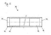
- the middle element 10 consists of a round hollow tube two end faces 11, 12 (see Fig. 2). Starting from the End faces is the inner diameter of the central element in a section 16 widened to the use of two polyamide rings 17 to enable. At the widened portion 16 closes in each case a threaded sleeve 13, 14.
- the threaded sleeves 13, 14 can also by a in the inner surface of the Middle element cut thread to be replaced. there has one of the threaded sleeves 13, 14 a right-hand thread and the others of the threaded sleeves 13, 14 a left-hand thread.
- the threaded sleeves 13, 14 are secured against rotation in the middle element 10 attached, for example by gluing.
- each one of the fasteners 30, 40 used.
- the fasteners in each case a shaft 32, 42, which one of the respective Threaded sleeve 13, 14 has corresponding thread.
- the free Ends of the shafts 32, 42 terminate in an end face 33, 43. the two fasteners 30, 40 can thus in the in the middle element 10 inserted threaded sleeves 13, 14 screwed become.
- the polyamide rings 17 seal the shafts 32, 42 of the fasteners 30, 40 against the middle element 10 from. After use the polyamide rings 17 in the sections 16 become the polyamide rings 17 crimped (see Fig. 1a), the tightness to increase and in particular the penetration of water in the Interior of the central element 10 to prevent.
- a disc 50 is placed, which glued example or riveted to ensure that the fastener 40 not completely unscrewed from the thread 13 can be.
- the toothed disc 20 On the end face 33 of the first fastening element 30 is a toothed disc 20 is placed, which also firmly with the Shank 32 is connected, for example by riveting or Bonding.
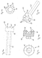
- the toothed disc 20 has a smooth bottom surface 22 and an end face 21 on which a plurality of radially extending Teeth 25 with flanks 26, tooth tips 27 and tooth reasons 28 are arranged (see Figures 3a to 3d).
- the flanks 26 of the teeth 25 are at right angles arranged to each other so that symmetrical teeth arise.
- the teeth can also be asymmetric or wavy be educated.
- the tooth tips 27 have a radius on and are thus slightly rounded, so that the movement Tooth tips does not lead to excessive loads.
- In the planar bottom surface 22 of the toothed disc 20 is a recess let into which the shaft 33 of the fastener 30 is used.
- the counter-toothed disc 60 In the interior of the central element 10 is a counter-toothed disc 60 slidably arranged.
- the counter-toothed disc 60 has a smooth back surface 62 and an end face 61 on which a plurality of radially extending teeth 65 with flanks 66, tooth tips 67 and tooth bases 68 are arranged (see Figures 4a to 4e).
- the flanks 66 are the teeth 65 arranged at right angles to each other, so that give symmetrical teeth.
- the tooth tips 67 are also slightly rounded.
- the counter-toothed disc 60 is so in the interior arranged the center element 10 that its end face 61 of End face 21 of the arranged on the fastening element 30 Toothed wheel 20 faces.
- the teeth 25 of the toothed disc 20th are thus in engagement with the teeth 65 of the counter-toothed disc 60 and form a gearing. Due to the symmetrical design Teeth 25 and 65 is an optimal positive fit Intervention ensured.
- a guide sleeve 80 is inserted, which in its outer diameter with the inner diameter of Middle element 10 matches.
- the guide sleeve 80 is thus pressed against rotation in the middle element 10.
- the twist resistance can be extra profiled Surfaces on the inner surface of the central elements 10 or on the outer surface of the guide sleeve 80 are attached.
- the guide sleeve 81 has an axial passage opening 81 with the inner contour of a polygon on.
- the inner contour of the Axial passage opening 81 corresponds to the outer contour of the polygonal shaft 63 of the counter-toothed disc 60, so that the Counter toothed disc 60 movable in the guide sleeve 80 slidably is.
- the inner contour of the passage opening 81 or the outer contour of the polygonal shaft 63 may be any polygon be, which the torsional security of the polygonal shaft Guaranteed 63 relative to the guide sleeve 80.
- the polygonal shaft 63 as a cylindrical tube with a be formed on the surface axially extending groove in which a correspondingly shaped bridge an otherwise cylindrical trained passage opening 81 engages.
- present is the cross section of the polygonal shaft 63 and the cross section the passage opening 81 formed as a regular 6-corner. The polygonal shaft 63 is thus in the passage opening 81 displaceable.
- a spring element 70 in the present case a spiral spring, arranged, which against the guide sleeve 80 and the back surface 62nd the counter-toothed disc 60 is supported and thus an admission the counter-toothed disc 60 causes.
- the movable counter-toothed disc 60 is thus always against the toothed disc 20 of the fastener 30 is pressed (see Fig. 1a, 1b).
- Both the toothed disc 20 and the counter tooth 60th are over the entire circumference with radially extending, equidistant arranged teeth 25, 65 provided.
- both the toothed disc 20 and the counter-toothed disc 60 also only partially with radially extending Be equipped teeth.
- the outer contours of the polygonal shaft 63 allow a game in the passage opening 81.
- the advantage of such a game is that, if at a rotation of the central element 10, the teeth 25 of the toothed disc 20 with its tip 27 not completely in the tooth surfaces 68 should slide, but on the flanks 66 of the teeth 65 of the counter-toothed disc 60 are should remain, the polygonal tube 63 of the counter-toothed disk 60 due to the approved clearance in the axial through hole 81 against the central element 10 and thus against the Sprocket 20 of the shaft 32 of the fastener 30 slightly can move, causing the teeth 25 of the toothed disc 20 due to the loading by the spring element 70 in the tooth surfaces 68 between the teeth 65 of the counter-toothed disc 60 can slip, so that in each position a positive fit Engagement of the toothed disc 20 in the counter-toothed disc 60th is guaranteed.
- the suspension element according to the invention operates in the following manner. Upon rotation of the central element 10 with fixed fasteners 30, 40 is due to the opposing thread the two threaded sleeves 13, 14, the length of the suspension element characterized in that either both fasteners 30, 40 pulled into the middle element 10 or pushed out become. The rotation of the central element 10 is facilitates the user that on the surface of the Middle element 10 is arranged a profile structure.
- the maximum change in length of the suspension depends from the length of the thread on the shank of the fastener 30, 40 and the length of the threaded sleeves 13, 14 and can be up to 100 mm.
- the total length of the different ones Types of suspension elements varies between 20 and 2000 mm
- the design of the fasteners is of the application depending on the suspension elements.
- the first fastener 30 as a condyle educated.
- the second fastening element 40 is designed as a clevis.
- the type of fasteners is not essential to the invention. In particular, you can also both fasteners 30, 40 as a joint head or as Clevis be formed.
Applications Claiming Priority (2)
| Application Number | Priority Date | Filing Date | Title |
|---|---|---|---|
| DE102004020000A DE102004020000B4 (de) | 2004-04-21 | 2004-04-21 | Abhängeelement |
| DE102004020000 | 2004-04-21 |
Publications (3)
| Publication Number | Publication Date |
|---|---|
| EP1588975A2 true EP1588975A2 (fr) | 2005-10-26 |
| EP1588975A3 EP1588975A3 (fr) | 2008-12-03 |
| EP1588975B1 EP1588975B1 (fr) | 2012-04-11 |
Family
ID=34935508
Family Applications (1)
| Application Number | Title | Priority Date | Filing Date |
|---|---|---|---|
| EP05008722A Active EP1588975B1 (fr) | 2004-04-21 | 2005-04-21 | Attelage |
Country Status (4)
| Country | Link |
|---|---|
| EP (1) | EP1588975B1 (fr) |
| AT (1) | ATE553055T1 (fr) |
| DE (1) | DE102004020000B4 (fr) |
| ES (1) | ES2385665T3 (fr) |
Cited By (10)
| Publication number | Priority date | Publication date | Assignee | Title |
|---|---|---|---|---|
| DE202009016397U1 (de) | 2009-12-02 | 2010-03-25 | Ro-Ra Produktions Gmbh | Zug-Druck-Stange |
| DE202010008858U1 (de) | 2010-10-21 | 2010-12-16 | Ro-Ra Produktions Gmbh | Zug-Druck-Stange |
| EP2320100A1 (fr) | 2009-11-10 | 2011-05-11 | RO-RA Produktions GmbH | Barre de traction-compression |
| WO2011057627A1 (fr) | 2009-11-10 | 2011-05-19 | Ro-Ra Produktions Gmbh | Lanterne de serrage |
| CN102221067A (zh) * | 2010-04-15 | 2011-10-19 | 路德链条里格及荻茨联合有限公司 | 用于链条的拉紧装置 |
| CN105570265A (zh) * | 2014-04-18 | 2016-05-11 | 王玲燕 | 一种核电站用连接件 |
| EP3647607A1 (fr) | 2018-10-31 | 2020-05-06 | SACS GmbH | Dispositif bielle |
| WO2020164704A1 (fr) * | 2019-02-13 | 2020-08-20 | Gmt Gummi-Metall-Technik Gmbh | Douille de raccordement, barre de traction-compression et procédé pour la fabrication d'une barre de traction-compression |
| EP3865717A1 (fr) * | 2020-02-14 | 2021-08-18 | on.gmbh | Montant télescopique |
| WO2022053293A1 (fr) * | 2020-09-10 | 2022-03-17 | Westdeutscher Drahtseil-Verkauf Dolezych Gmbh & Co. Kg | Dispositif de mise en tension |
Families Citing this family (3)
| Publication number | Priority date | Publication date | Assignee | Title |
|---|---|---|---|---|
| DE102011053063B3 (de) * | 2011-08-29 | 2013-02-28 | Jürgen Freigeber | Spannschloss für Zurrketten oder Zurrbänder zum Festzurren von Ladungen insbesondere auf Fahrzeugen |
| WO2013164243A1 (fr) | 2012-05-02 | 2013-11-07 | Jet Aviation Ag | Tête de tirant |
| DE202012102522U1 (de) * | 2012-07-09 | 2013-10-11 | Pfeifer Holding Gmbh & Co. Kg | Endverbindung, insbesondere für das Verbinden von Zugelementen |
Citations (3)
| Publication number | Priority date | Publication date | Assignee | Title |
|---|---|---|---|---|
| GB524717A (en) * | 1939-02-04 | 1940-08-13 | Francis William Kennedy | Improvements relating to adjustable turnbuckles or like tensioning-devices |
| DE720193C (de) * | 1941-04-06 | 1942-04-28 | Ernst Heinkel Flugzeugwerke G | Spannschlosssicherung fuer den Luftfahrzeugbau |
| DE20307918U1 (de) * | 2002-12-31 | 2003-07-31 | Hsieh David | Positionierungsanordnung zur Positionierung eines Containers auf einer Plattform |
Family Cites Families (5)
| Publication number | Priority date | Publication date | Assignee | Title |
|---|---|---|---|---|
| US2352585A (en) * | 1943-07-03 | 1944-06-27 | Ronan & Kunzl | Self-locking turnbuckle |
| US2810595A (en) * | 1953-02-12 | 1957-10-22 | George W Purdy | Turnbuckles |
| US2859991A (en) * | 1956-04-04 | 1958-11-11 | Wadsworth W Mount | Self-locking turnbuckle |
| SE7309714L (sv) * | 1973-07-11 | 1975-01-13 | Mustad Ab J | Vantskruv. |
| US5702196A (en) * | 1996-06-21 | 1997-12-30 | Teleflex, Incorporated | Turnbuckle-type adjustable link |
-
2004
- 2004-04-21 DE DE102004020000A patent/DE102004020000B4/de not_active Expired - Fee Related
-
2005
- 2005-04-21 ES ES05008722T patent/ES2385665T3/es active Active
- 2005-04-21 AT AT05008722T patent/ATE553055T1/de active
- 2005-04-21 EP EP05008722A patent/EP1588975B1/fr active Active
Patent Citations (3)
| Publication number | Priority date | Publication date | Assignee | Title |
|---|---|---|---|---|
| GB524717A (en) * | 1939-02-04 | 1940-08-13 | Francis William Kennedy | Improvements relating to adjustable turnbuckles or like tensioning-devices |
| DE720193C (de) * | 1941-04-06 | 1942-04-28 | Ernst Heinkel Flugzeugwerke G | Spannschlosssicherung fuer den Luftfahrzeugbau |
| DE20307918U1 (de) * | 2002-12-31 | 2003-07-31 | Hsieh David | Positionierungsanordnung zur Positionierung eines Containers auf einer Plattform |
Cited By (19)
| Publication number | Priority date | Publication date | Assignee | Title |
|---|---|---|---|---|
| AT508984B1 (de) * | 2009-11-10 | 2011-07-15 | Ro Ra Produktions Gmbh | Zug-druck-stange |
| EP2320100A1 (fr) | 2009-11-10 | 2011-05-11 | RO-RA Produktions GmbH | Barre de traction-compression |
| WO2011057627A1 (fr) | 2009-11-10 | 2011-05-19 | Ro-Ra Produktions Gmbh | Lanterne de serrage |
| DE202009016397U1 (de) | 2009-12-02 | 2010-03-25 | Ro-Ra Produktions Gmbh | Zug-Druck-Stange |
| EP2690312A1 (fr) * | 2010-04-15 | 2014-01-29 | RUD Ketten Rieger & Dietz GmbH u. Co. KG | Dispositif de serrage pour chaînes |
| AU2016228214B2 (en) * | 2010-04-15 | 2018-09-20 | Rud Ketten Rieger & Dietz Gmbh U. Co. Kg | Tensioning device for chains |
| DE102010015266A1 (de) * | 2010-04-15 | 2011-10-20 | Rud Ketten Rieger & Dietz Gmbh U. Co. Kg | Spannvorrichtung für Ketten |
| EP2378158A3 (fr) * | 2010-04-15 | 2012-11-28 | RUD Ketten Rieger & Dietz GmbH u. Co. KG | Dispositif de serrage pour chaînes |
| CN102221067A (zh) * | 2010-04-15 | 2011-10-19 | 路德链条里格及荻茨联合有限公司 | 用于链条的拉紧装置 |
| CN102221067B (zh) * | 2010-04-15 | 2014-05-14 | 路德链条里格及荻茨联合有限公司 | 用于链条的拉紧装置 |
| CN104019187A (zh) * | 2010-04-15 | 2014-09-03 | 路德链条里格及荻茨联合有限公司 | 用于链条的拉紧装置 |
| US9103405B2 (en) | 2010-04-15 | 2015-08-11 | Rud Ketten Rieger & Dietz Gmbh U. Co. Kg | Tensioning device for chains |
| DE202010008858U1 (de) | 2010-10-21 | 2010-12-16 | Ro-Ra Produktions Gmbh | Zug-Druck-Stange |
| CN105570265A (zh) * | 2014-04-18 | 2016-05-11 | 王玲燕 | 一种核电站用连接件 |
| EP3647607A1 (fr) | 2018-10-31 | 2020-05-06 | SACS GmbH | Dispositif bielle |
| WO2020089111A1 (fr) | 2018-10-31 | 2020-05-07 | Sacs Aerospace Gmbh | Dispositif de couplage |
| WO2020164704A1 (fr) * | 2019-02-13 | 2020-08-20 | Gmt Gummi-Metall-Technik Gmbh | Douille de raccordement, barre de traction-compression et procédé pour la fabrication d'une barre de traction-compression |
| EP3865717A1 (fr) * | 2020-02-14 | 2021-08-18 | on.gmbh | Montant télescopique |
| WO2022053293A1 (fr) * | 2020-09-10 | 2022-03-17 | Westdeutscher Drahtseil-Verkauf Dolezych Gmbh & Co. Kg | Dispositif de mise en tension |
Also Published As
| Publication number | Publication date |
|---|---|
| DE102004020000A1 (de) | 2005-11-10 |
| EP1588975A3 (fr) | 2008-12-03 |
| ATE553055T1 (de) | 2012-04-15 |
| DE102004020000B4 (de) | 2006-06-01 |
| ES2385665T3 (es) | 2012-07-30 |
| EP1588975B1 (fr) | 2012-04-11 |
Similar Documents
| Publication | Publication Date | Title |
|---|---|---|
| EP1588975B1 (fr) | Attelage | |
| EP1961976B1 (fr) | Dispositif de fixation | |
| DE102006029253B3 (de) | Scheibe und damit versehene Schraubenverbindung | |
| DE112012000062T5 (de) | Vorrichtung zum Festziehen von mit Gewinden versehenen Befestigungsmittel | |
| EP3565976B1 (fr) | Dispositif de limitation de couple comportant trois brides | |
| DE4030978C2 (de) | Verbindungseinrichtung für Rohre | |
| DE202012013475U1 (de) | Profilverbindung | |
| DE2708538C3 (de) | Verbindung zwischen den Kettengliedern einer Gleiskette | |
| DE102005007754B3 (de) | Toleranzausgleichselement | |
| AT401080B (de) | Halter für die biegemomentfreie lagerung von glasplatten | |
| DE102016209395A1 (de) | Befestigungselement für den Toleranzausgleich | |
| DE1400801A1 (de) | Kontermutter und Verfahren zu ihrer Herstellung | |
| DE19906480A1 (de) | Hülsenmutter | |
| DE10248102B4 (de) | Verfahren zum Fügen von Stahlelementen mit einer Schraube | |
| DE102006053298A1 (de) | Vorrichtung zum Blockieren einer Radaufhängung eines Fahrzeugs | |
| DE1961980B2 (de) | Nabenbefestigung | |
| DE4316808C2 (de) | Spannstück für Rohrelemente | |
| EP3470693A1 (fr) | Écrou | |
| WO2018224237A1 (fr) | Moyens de serrage intérieur à bague segmentée de serrage bloquée | |
| AT503129B1 (de) | Verbindungsbeschlag für holzteile | |
| DE102004051669B4 (de) | Selbstsichernde Schraube und selbstsichernde Befestigungsanordnung | |
| EP0604696B1 (fr) | Dispositif de fixation | |
| DE19527602A1 (de) | Vorrichtung zum Befestigen von Gegenständen | |
| EP2159433B1 (fr) | Dispositif de fixation amovible | |
| DE102015225258A1 (de) | Befestigungsvorrichtung, insbesondere für eine Leuchte, sowie Leuchte |
Legal Events
| Date | Code | Title | Description |
|---|---|---|---|
| PUAI | Public reference made under article 153(3) epc to a published international application that has entered the european phase |
Free format text: ORIGINAL CODE: 0009012 |
|
| AK | Designated contracting states |
Kind code of ref document: A2 Designated state(s): AT BE BG CH CY CZ DE DK EE ES FI FR GB GR HU IE IS IT LI LT LU MC NL PL PT RO SE SI SK TR |
|
| AX | Request for extension of the european patent |
Extension state: AL BA HR LV MK YU |
|
| PUAL | Search report despatched |
Free format text: ORIGINAL CODE: 0009013 |
|
| AK | Designated contracting states |
Kind code of ref document: A3 Designated state(s): AT BE BG CH CY CZ DE DK EE ES FI FR GB GR HU IE IS IT LI LT LU MC NL PL PT RO SE SI SK TR |
|
| AX | Request for extension of the european patent |
Extension state: AL BA HR LV MK YU |
|
| RIC1 | Information provided on ipc code assigned before grant |
Ipc: F16G 11/12 20060101ALI20081029BHEP Ipc: B66B 7/08 20060101AFI20050718BHEP Ipc: F16B 7/06 20060101ALI20081029BHEP |
|
| 17P | Request for examination filed |
Effective date: 20090220 |
|
| AKX | Designation fees paid |
Designated state(s): AT BE BG CH CY CZ DE DK EE ES FI FR GB GR HU IE IS IT LI LT LU MC NL PL PT RO SE SI SK TR |
|
| 17Q | First examination report despatched |
Effective date: 20100122 |
|
| GRAP | Despatch of communication of intention to grant a patent |
Free format text: ORIGINAL CODE: EPIDOSNIGR1 |
|
| GRAS | Grant fee paid |
Free format text: ORIGINAL CODE: EPIDOSNIGR3 |
|
| GRAA | (expected) grant |
Free format text: ORIGINAL CODE: 0009210 |
|
| AK | Designated contracting states |
Kind code of ref document: B1 Designated state(s): AT BE BG CH CY CZ DE DK EE ES FI FR GB GR HU IE IS IT LI LT LU MC NL PL PT RO SE SI SK TR |
|
| REG | Reference to a national code |
Ref country code: GB Ref legal event code: FG4D Free format text: NOT ENGLISH |
|
| REG | Reference to a national code |
Ref country code: DE Ref legal event code: R081 Ref document number: 502005012607 Country of ref document: DE Owner name: SACS GMBH, DE Free format text: FORMER OWNER: SACS GMBH, 78628 ROTTWEIL, DE |
|
| REG | Reference to a national code |
Ref country code: CH Ref legal event code: EP |
|
| REG | Reference to a national code |
Ref country code: AT Ref legal event code: REF Ref document number: 553055 Country of ref document: AT Kind code of ref document: T Effective date: 20120415 |
|
| REG | Reference to a national code |
Ref country code: IE Ref legal event code: FG4D Free format text: LANGUAGE OF EP DOCUMENT: GERMAN |
|
| REG | Reference to a national code |
Ref country code: CH Ref legal event code: NV Representative=s name: R. A. EGLI & CO. PATENTANWAELTE |
|
| REG | Reference to a national code |
Ref country code: DE Ref legal event code: R096 Ref document number: 502005012607 Country of ref document: DE Effective date: 20120606 |
|
| REG | Reference to a national code |
Ref country code: ES Ref legal event code: FG2A Ref document number: 2385665 Country of ref document: ES Kind code of ref document: T3 Effective date: 20120730 |
|
| REG | Reference to a national code |
Ref country code: NL Ref legal event code: VDEP Effective date: 20120411 |
|
| LTIE | Lt: invalidation of european patent or patent extension |
Effective date: 20120411 |
|
| BERE | Be: lapsed |
Owner name: SACS G.M.B.H. Effective date: 20120430 |
|
| PG25 | Lapsed in a contracting state [announced via postgrant information from national office to epo] |
Ref country code: PL Free format text: LAPSE BECAUSE OF FAILURE TO SUBMIT A TRANSLATION OF THE DESCRIPTION OR TO PAY THE FEE WITHIN THE PRESCRIBED TIME-LIMIT Effective date: 20120411 Ref country code: LT Free format text: LAPSE BECAUSE OF FAILURE TO SUBMIT A TRANSLATION OF THE DESCRIPTION OR TO PAY THE FEE WITHIN THE PRESCRIBED TIME-LIMIT Effective date: 20120411 Ref country code: IS Free format text: LAPSE BECAUSE OF FAILURE TO SUBMIT A TRANSLATION OF THE DESCRIPTION OR TO PAY THE FEE WITHIN THE PRESCRIBED TIME-LIMIT Effective date: 20120811 Ref country code: CY Free format text: LAPSE BECAUSE OF FAILURE TO SUBMIT A TRANSLATION OF THE DESCRIPTION OR TO PAY THE FEE WITHIN THE PRESCRIBED TIME-LIMIT Effective date: 20120411 Ref country code: FI Free format text: LAPSE BECAUSE OF FAILURE TO SUBMIT A TRANSLATION OF THE DESCRIPTION OR TO PAY THE FEE WITHIN THE PRESCRIBED TIME-LIMIT Effective date: 20120411 Ref country code: SE Free format text: LAPSE BECAUSE OF FAILURE TO SUBMIT A TRANSLATION OF THE DESCRIPTION OR TO PAY THE FEE WITHIN THE PRESCRIBED TIME-LIMIT Effective date: 20120411 |
|
| PG25 | Lapsed in a contracting state [announced via postgrant information from national office to epo] |
Ref country code: SI Free format text: LAPSE BECAUSE OF FAILURE TO SUBMIT A TRANSLATION OF THE DESCRIPTION OR TO PAY THE FEE WITHIN THE PRESCRIBED TIME-LIMIT Effective date: 20120411 Ref country code: GR Free format text: LAPSE BECAUSE OF FAILURE TO SUBMIT A TRANSLATION OF THE DESCRIPTION OR TO PAY THE FEE WITHIN THE PRESCRIBED TIME-LIMIT Effective date: 20120712 Ref country code: PT Free format text: LAPSE BECAUSE OF FAILURE TO SUBMIT A TRANSLATION OF THE DESCRIPTION OR TO PAY THE FEE WITHIN THE PRESCRIBED TIME-LIMIT Effective date: 20120813 Ref country code: MC Free format text: LAPSE BECAUSE OF NON-PAYMENT OF DUE FEES Effective date: 20120430 |
|
| REG | Reference to a national code |
Ref country code: IE Ref legal event code: MM4A |
|
| PG25 | Lapsed in a contracting state [announced via postgrant information from national office to epo] |
Ref country code: DK Free format text: LAPSE BECAUSE OF FAILURE TO SUBMIT A TRANSLATION OF THE DESCRIPTION OR TO PAY THE FEE WITHIN THE PRESCRIBED TIME-LIMIT Effective date: 20120411 Ref country code: EE Free format text: LAPSE BECAUSE OF FAILURE TO SUBMIT A TRANSLATION OF THE DESCRIPTION OR TO PAY THE FEE WITHIN THE PRESCRIBED TIME-LIMIT Effective date: 20120411 Ref country code: IE Free format text: LAPSE BECAUSE OF NON-PAYMENT OF DUE FEES Effective date: 20120421 Ref country code: CZ Free format text: LAPSE BECAUSE OF FAILURE TO SUBMIT A TRANSLATION OF THE DESCRIPTION OR TO PAY THE FEE WITHIN THE PRESCRIBED TIME-LIMIT Effective date: 20120411 Ref country code: RO Free format text: LAPSE BECAUSE OF FAILURE TO SUBMIT A TRANSLATION OF THE DESCRIPTION OR TO PAY THE FEE WITHIN THE PRESCRIBED TIME-LIMIT Effective date: 20120411 Ref country code: BE Free format text: LAPSE BECAUSE OF NON-PAYMENT OF DUE FEES Effective date: 20120430 Ref country code: SK Free format text: LAPSE BECAUSE OF FAILURE TO SUBMIT A TRANSLATION OF THE DESCRIPTION OR TO PAY THE FEE WITHIN THE PRESCRIBED TIME-LIMIT Effective date: 20120411 Ref country code: NL Free format text: LAPSE BECAUSE OF FAILURE TO SUBMIT A TRANSLATION OF THE DESCRIPTION OR TO PAY THE FEE WITHIN THE PRESCRIBED TIME-LIMIT Effective date: 20120411 |
|
| PLBE | No opposition filed within time limit |
Free format text: ORIGINAL CODE: 0009261 |
|
| STAA | Information on the status of an ep patent application or granted ep patent |
Free format text: STATUS: NO OPPOSITION FILED WITHIN TIME LIMIT |
|
| 26N | No opposition filed |
Effective date: 20130114 |
|
| REG | Reference to a national code |
Ref country code: DE Ref legal event code: R097 Ref document number: 502005012607 Country of ref document: DE Effective date: 20130114 |
|
| PG25 | Lapsed in a contracting state [announced via postgrant information from national office to epo] |
Ref country code: BG Free format text: LAPSE BECAUSE OF FAILURE TO SUBMIT A TRANSLATION OF THE DESCRIPTION OR TO PAY THE FEE WITHIN THE PRESCRIBED TIME-LIMIT Effective date: 20120711 |
|
| PG25 | Lapsed in a contracting state [announced via postgrant information from national office to epo] |
Ref country code: TR Free format text: LAPSE BECAUSE OF FAILURE TO SUBMIT A TRANSLATION OF THE DESCRIPTION OR TO PAY THE FEE WITHIN THE PRESCRIBED TIME-LIMIT Effective date: 20120411 |
|
| PG25 | Lapsed in a contracting state [announced via postgrant information from national office to epo] |
Ref country code: LU Free format text: LAPSE BECAUSE OF NON-PAYMENT OF DUE FEES Effective date: 20120421 |
|
| PG25 | Lapsed in a contracting state [announced via postgrant information from national office to epo] |
Ref country code: HU Free format text: LAPSE BECAUSE OF FAILURE TO SUBMIT A TRANSLATION OF THE DESCRIPTION OR TO PAY THE FEE WITHIN THE PRESCRIBED TIME-LIMIT Effective date: 20050421 |
|
| REG | Reference to a national code |
Ref country code: DE Ref legal event code: R082 Ref document number: 502005012607 Country of ref document: DE Representative=s name: WESTPHAL, MUSSGNUG & PARTNER PATENTANWAELTE MI, DE Ref country code: DE Ref legal event code: R081 Ref document number: 502005012607 Country of ref document: DE Owner name: SACS GMBH, DE Free format text: FORMER OWNER: SACS GMBH, 78628 ROTTWEIL, DE Ref country code: DE Ref legal event code: R082 Ref document number: 502005012607 Country of ref document: DE Representative=s name: PATENTANWAELTE MAGENBAUER & KOLLEGEN PARTNERSC, DE |
|
| REG | Reference to a national code |
Ref country code: FR Ref legal event code: PLFP Year of fee payment: 12 |
|
| REG | Reference to a national code |
Ref country code: DE Ref legal event code: R082 Ref document number: 502005012607 Country of ref document: DE Representative=s name: PATENTANWAELTE MAGENBAUER & KOLLEGEN PARTNERSC, DE |
|
| REG | Reference to a national code |
Ref country code: FR Ref legal event code: PLFP Year of fee payment: 13 |
|
| REG | Reference to a national code |
Ref country code: FR Ref legal event code: PLFP Year of fee payment: 14 |
|
| PGFP | Annual fee paid to national office [announced via postgrant information from national office to epo] |
Ref country code: ES Payment date: 20190520 Year of fee payment: 15 Ref country code: IT Payment date: 20190419 Year of fee payment: 15 |
|
| PGFP | Annual fee paid to national office [announced via postgrant information from national office to epo] |
Ref country code: FR Payment date: 20210421 Year of fee payment: 17 |
|
| PGFP | Annual fee paid to national office [announced via postgrant information from national office to epo] |
Ref country code: GB Payment date: 20210422 Year of fee payment: 17 Ref country code: CH Payment date: 20210422 Year of fee payment: 17 |
|
| REG | Reference to a national code |
Ref country code: ES Ref legal event code: FD2A Effective date: 20210902 |
|
| PG25 | Lapsed in a contracting state [announced via postgrant information from national office to epo] |
Ref country code: IT Free format text: LAPSE BECAUSE OF NON-PAYMENT OF DUE FEES Effective date: 20200421 |
|
| PG25 | Lapsed in a contracting state [announced via postgrant information from national office to epo] |
Ref country code: ES Free format text: LAPSE BECAUSE OF NON-PAYMENT OF DUE FEES Effective date: 20200422 |
|
| REG | Reference to a national code |
Ref country code: CH Ref legal event code: PL |
|
| GBPC | Gb: european patent ceased through non-payment of renewal fee |
Effective date: 20220421 |
|
| PG25 | Lapsed in a contracting state [announced via postgrant information from national office to epo] |
Ref country code: LI Free format text: LAPSE BECAUSE OF NON-PAYMENT OF DUE FEES Effective date: 20220430 Ref country code: GB Free format text: LAPSE BECAUSE OF NON-PAYMENT OF DUE FEES Effective date: 20220421 Ref country code: FR Free format text: LAPSE BECAUSE OF NON-PAYMENT OF DUE FEES Effective date: 20220430 Ref country code: CH Free format text: LAPSE BECAUSE OF NON-PAYMENT OF DUE FEES Effective date: 20220430 |
|
| P01 | Opt-out of the competence of the unified patent court (upc) registered |
Effective date: 20230524 |
|
| PGFP | Annual fee paid to national office [announced via postgrant information from national office to epo] |
Ref country code: DE Payment date: 20230320 Year of fee payment: 19 |
|
| PGFP | Annual fee paid to national office [announced via postgrant information from national office to epo] |
Ref country code: AT Payment date: 20230414 Year of fee payment: 19 |