EP1588892B1 - Armlehne und Sitz mit der Armlehne - Google Patents
Armlehne und Sitz mit der Armlehne Download PDFInfo
- Publication number
- EP1588892B1 EP1588892B1 EP05008019A EP05008019A EP1588892B1 EP 1588892 B1 EP1588892 B1 EP 1588892B1 EP 05008019 A EP05008019 A EP 05008019A EP 05008019 A EP05008019 A EP 05008019A EP 1588892 B1 EP1588892 B1 EP 1588892B1
- Authority
- EP
- European Patent Office
- Prior art keywords
- arm rest
- guide rails
- armrest
- seat
- vehicle
- Prior art date
- Legal status (The legal status is an assumption and is not a legal conclusion. Google has not performed a legal analysis and makes no representation as to the accuracy of the status listed.)
- Expired - Lifetime
Links
Images


Classifications
-
- A—HUMAN NECESSITIES
- A47—FURNITURE; DOMESTIC ARTICLES OR APPLIANCES; COFFEE MILLS; SPICE MILLS; SUCTION CLEANERS IN GENERAL
- A47C—CHAIRS; SOFAS; BEDS
- A47C1/00—Chairs adapted for special purposes
- A47C1/02—Reclining or easy chairs
- A47C1/022—Reclining or easy chairs having independently-adjustable supporting parts
- A47C1/03—Reclining or easy chairs having independently-adjustable supporting parts the parts being arm-rests
-
- B—PERFORMING OPERATIONS; TRANSPORTING
- B60—VEHICLES IN GENERAL
- B60N—SEATS SPECIALLY ADAPTED FOR VEHICLES; VEHICLE PASSENGER ACCOMMODATION NOT OTHERWISE PROVIDED FOR
- B60N2/00—Seats specially adapted for vehicles; Arrangement or mounting of seats in vehicles
- B60N2/75—Arm-rests
- B60N2/763—Arm-rests adjustable
- B60N2/77—Height adjustment
-
- B—PERFORMING OPERATIONS; TRANSPORTING
- B60—VEHICLES IN GENERAL
- B60N—SEATS SPECIALLY ADAPTED FOR VEHICLES; VEHICLE PASSENGER ACCOMMODATION NOT OTHERWISE PROVIDED FOR
- B60N2/00—Seats specially adapted for vehicles; Arrangement or mounting of seats in vehicles
- B60N2/75—Arm-rests
- B60N2/763—Arm-rests adjustable
- B60N2/773—Longitudinal adjustment
-
- B—PERFORMING OPERATIONS; TRANSPORTING
- B60—VEHICLES IN GENERAL
- B60N—SEATS SPECIALLY ADAPTED FOR VEHICLES; VEHICLE PASSENGER ACCOMMODATION NOT OTHERWISE PROVIDED FOR
- B60N2/00—Seats specially adapted for vehicles; Arrangement or mounting of seats in vehicles
- B60N2/02—Seats specially adapted for vehicles; Arrangement or mounting of seats in vehicles the seat or part thereof being movable, e.g. adjustable
- B60N2002/0204—Seats specially adapted for vehicles; Arrangement or mounting of seats in vehicles the seat or part thereof being movable, e.g. adjustable characterised by the seat or seat part turning about or moving along a non-standard, particular axis, i.e. an axis different from the axis characterising the conventional movement
- B60N2002/0208—Seats specially adapted for vehicles; Arrangement or mounting of seats in vehicles the seat or part thereof being movable, e.g. adjustable characterised by the seat or seat part turning about or moving along a non-standard, particular axis, i.e. an axis different from the axis characterising the conventional movement the seat or seat part turning about or moving along an inclined axis
Definitions
- an armrest comprising a fixed part, which carries a movable between two positions Ellebogen matter, said moving is accomplished by an arcuate sliding in a housing part.
- FIG. 1 shows as an embodiment of the invention, a side view of an armrest in the context of a center console of a passenger car.
- the armrest comprises a lower part 10, which is for example firmly connected between the driver and passenger seat of the passenger vehicle with this. Furthermore, the armrest comprises a movable against the lower part 10 trained Upper part 20, which is connected via guide rails 32 and 31 with the lower part 10.
- An upper surface of the upper part 20 is preferably formed padded for placing at least a portion of a human arm. Seen from the lower part 10, said surface is convex.
- FIG. 1 is shown by solid lines, a first end position of the upper part 20 and with dotted line a second end position of the upper part 20. Due to the curved design of the guide rails 31 and 32, the upper part 20 is displaced in an advantageous manner when moving the upper part 20 adapted to the ergonomics in both the horizontal and vertical directions.
- the FIG. 2 shows in a side view two cooperating guide rails 31 and 32 of the armrest of FIG. 1 ,
- the longer guide rail 31 is arranged in the lower part 10 and the shorter guide rail 32 is connected to the upper part 20 accordingly.
- the longer guide rail may be arranged to the upper part and the shorter the lower part associated or both guide rails are formed of equal length.
- the guided in the cage 36 ball-like rolling elements 35 are arranged in the FIG. 2 are shown with dashed thin lines.
- the FIG. 2 shows the guide rails 31 and 32 in the first end position.
- the FIG. 3 further shows a cross section of the rolling bearing assembly of FIG. 2 at the in the FIG. 2 AA-designated cross-sectional area.
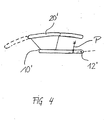
- FIG. 4 shows as a further embodiment of the invention, a side view of another armrest.
- the further armrest on a lower part 10 ', which is arranged pivotably about a rotation axis 12' according to the curved double arrow P.
- the armrest comprises a lower part 10 'movable upper part 20', which is connected via guide rails with the lower part 10 '.
- An upper surface of the upper part 20 ' is preferably padded for laying on at least a part of a human arm. Seen from the lower part 10 'from the said surface is convex.
- the cooperating arcuate guide rails which are seen from the lower part 10 'of convex.
- the upper part 20 'and the lower part 10' in each case comprise two guide rails, wherein in each case one of the guide rails of the upper part 20 'cooperates with one of the guide rails of the lower part 10'.
- the cooperating guide rails are slidably intermeshed. In the FIG. 4 is shown by a solid line a first end position of the upper part 20 'and with a dashed line a second end position of the upper part 20'.
Landscapes
- Engineering & Computer Science (AREA)
- Health & Medical Sciences (AREA)
- Dentistry (AREA)
- General Health & Medical Sciences (AREA)
- Aviation & Aerospace Engineering (AREA)
- Transportation (AREA)
- Mechanical Engineering (AREA)
- Seats For Vehicles (AREA)
- Passenger Equipment (AREA)
- Vehicle Step Arrangements And Article Storage (AREA)
Description
- Die Erfindung betrifft eine Armlehne, umfassend ein befestigbares Unterteil und ein gegen das Unterteil bewegbares Oberteil, und einen Sitz mit der Armlehne.
- Aus der
DE 197 01 388 A1 ist eine Armlehne für einen Fahrzeugsitz bekannt, die zur Verstellung in der Höhe und zur gleichzeitigen Verstellung in Sitzlängsrichtung mit einer Gelenkeinrichtung verbunden ist, die einen ersten und einen zweiten Schwenkhebel aufweist, die zueinander mindestens annähernd parallel vorgesehen sind. Die der vorausgehend beschriebenen Armlehne zugrundeliegende Mechanik ist dabei vergleichsweise komplex. - Aus der
WO 03/068025 A2 - Aus der
DE 44 15 264 C2 ist eine Armlehne eines Bürodrehstuhls bekannt, die über eine bogenartige Führung vor- und rückbewegbar ist. - Aus der
EP 1 245 438 A1 ist eine motorisch verstellbare Armlehne im Mittelkonsolenbereich eines Kraftfahrzeugs bekannt. - Aus der
FR 2 749 233 A1 - Aus der
JP 60-213519 A - Eine Aufgabe der Erfindung ist es, eine verbesserte Armlehne, die sowohl in der Höhe als auch in Armlehnenlängsrichtung verstellbar ist, zu schaffen, so dass die Armlehne insbesondere einen einfachen mechanischen Aufbau aufweist.
- Die Aufgabe wird durch den Gegenstand des Anspruchs 1 gelöst. Vorteilhafte Ausgestaltungen sind in den Unteransprüchen beschrieben.
- Gemäß Anspruch 1 umfasst eine Armlehne ein befestigbares Unterteil und ein gegen das Unterteil für wenigstens eine Höhenverstellbarkeit der Armlehne bewegbares Oberteil, wobei die Teile jeweils wenigstens eine Führungsschiene umfassen, die Teile über die Führungsschienen gegeneinander bewegbar sind, die Führungsschienen zueinander passend in Armlehnenlängsrichtung bogenartig ausgebildet sind, und die Führungsschienen vom Unterteil aus gesehen zum Oberteil hin konkav oder konvex ausgebildet sind.
- Durch den Einsatz der gebogenen Führungsschienen wird mit besonderem Vorteil bei einem einfachen mechanischen Aufbau eine Verstellbarkeit der Armlehne sowohl in der Höhe als auch in Armlehnenlängsrichtung ermöglicht. Weiterhin sind damit hohe ergonomische und auch ästhetische Anforderungen erfüllbar. Durch eine entsprechende Wahl der Radien der Führungsschienen und/oder durch Ausnutzung einer Elastizität der Führungsschienen sind an die jeweilige Verwendung angepasste, unterschiedlichste Bewegungsbahnen des Oberteils realisierbar.
- Weitere Vorteile, Merkmale und Einzelheiten der Erfindung ergeben sich aus den im folgenden beschriebenen Ausführungsbeispielen anhand der Figuren. Dabei zeigen:
- Figur 1
- eine Seitenansicht einer Armlehne im Rahmen einer Mittelkonsole eines Personenkraftwagens,
- Figur 2
- eine Seitenansicht von Führungsschienen der Armlehne der
Figur 1 , - Figur 3
- einen Querschnitt durch die Führungsschienen der
Figur 2 und - Figur 4
- eine Seitenansicht einer weiteren Armlehne.
- Die
Figur 1 zeigt als ein Ausführungsbeispiel der Erfindung eine Seitenansicht einer Armlehne im Rahmen einer Mittelkonsole eines Personenkraftfahrzeugs. Die Armlehne umfasst dabei ein Unterteil 10, das beispielsweise fest zwischen dem Fahrer- und Beifahrersitz des Personenkraftfahrzeugs mit diesem verbunden ist. Weiterhin umfasst die Armlehne ein gegen das Unterteil 10 bewegbar ausgebildetes Oberteil 20, das über Führungsschienen 32 und 31 mit dem Unterteil 10 verbunden ist. Eine obere Oberfläche des Oberteils 20 ist dabei zum Auflegen wenigstens eines Teils eines menschlichen Arms bevorzugt gepolstert ausgebildet. Vom Unterteil 10 aus gesehen ist dabei die besagte Oberfläche konvex ausgebildet. - In einem unteren Bereich des Oberteils 20 hin zum Unterteil 10 sowie in einem oberen Bereich des Unterteils 10 hin zum Oberteil 20 sind die zusammenwirkenden bogenartigen Führungsschienen 31 und 32 angeordnet, die vom Unterteil 10 aus gesehen konkav ausgebildet sind. Das Oberteil 20 und das Unterteil 10 umfassen dabei jeweils zwei Führungsschienen 31 und 32, wobei jeweils eine der Führungsschienen 32 des Oberteils 20 mit jeweils einer der Führungsschienen 31 des Unterteils 10 zusammenwirkt. Zwischen den zusammenwirkenden Führungsschienen 31 und 32 sind in einem Käfig 36 angeordnete kugelförmige Wälzkörper 35 angeordnet. In einer anderen Ausführungsform sind die zusammenwirkenden Führungsschienen gleitend ineinandergreifend ausgebildet.
- In der
Figur 1 ist mit durchgezogenen Linien eine erste Endstellung des Oberteils 20 und mit strichpunktierter Linie eine zweite Endstellung des Oberteils 20 dargestellt. Aufgrund der gebogenen Ausbildung der Führungsschienen 31 und 32 wird dabei mit Vorteil bei einem Bewegen des Oberteils 20 das Oberteil 20 angepasst an die Ergonomie sowohl in horizontaler als auch vertikaler Richtung verschoben. Dabei erkennt man, dass zwischen den beiden Endstellungen ein maximaler Höhengewinn h an der Armlehne erzielbar ist und zwischen den beiden Endstellungen ein von der jeweiligen Endstellung abhängiger höchster Punkt des Oberteils 20 um eine Hublänge 1 verschiebbar ist, die in etwa einem 1,5 fachen einer tatsächlichen Hublänge k entspricht, wobei sich in anderen Ausführungsformen für vorgenanntes Vielfaches in Abhängigkeit von der Kontur besagter Oberfläche des Oberteils und den Biegeradien der Führungsschienen auch andere Werte ergeben können. Gegenüber geradlinigen, horizontal angeordneten Führungsschienen wird also der höchste Punkt zusätzlich verschoben. Bei jeder Stellung des Oberteils 20 ist dabei konstruktionsbedingt sichergestellt, dass ein Spalt zwischen dem Oberteil 20 und dem Unterteil 10 entlang der Führungsschienen 31 und 32 konstant bleibt, was unter anderem auch für die optische Ästhetik von Vorteil ist. Gegenüber vergleichbaren Lösungen, die für ein Verstellen in der Höhe und ein Verstellen in Armlehnenlängsrichtung separate Mechanismen nutzen, ergibt sich bei der Ausführungsform gemäß derFigur 1 ein Raumgewinn, der beispielsweise zum Unterbringen von Belüftungsauslässen 15 einer Belüftungsanlage nutzbar ist. - Die
Figur 2 zeigt in einer Seitenansicht zwei zusammenwirkende Führungsschienen 31 und 32 der Armlehne derFigur 1 . Dabei ist die längere Führungsschiene 31 im Unterteil 10 angeordnet und die kürzere Führungsschiene 32 mit dem Oberteil 20 entsprechend verbunden. In anderen Ausführungsformen kann auch die längere Führungsschiene dem Oberteil und die kürzere dem Unterteil zugehörig angeordnet sein oder es sind beide Führungsschienen gleich lang ausgebildet. Im Überdeckungsbereich zwischen den beiden Führungsschienen 31 und 32 sind die in dem Käfig 36 geführten kugelartigen Wälzkörper 35 angeordnet, die in derFigur 2 mit gestrichelten dünnen Linien dargestellt sind. DieFigur 2 zeigt dabei die Führungsschienen 31 und 32 in der ersten Endstellung. DieFigur 3 zeigt weiterhin einen Querschnitt der Wälzlageranordnung derFigur 2 an der in derFigur 2 mit AA bezeichneten Querschnittsfläche. - Die
Figur 4 zeigt als ein weiteres Ausführungsbeispiel der Erfindung eine Seitenansicht einer weiteren Armlehne. Dabei weist die weitere Armlehne ein Unterteil 10' auf, das um eine Drehachse 12' gemäß dem gebogenen Doppelpfeil P verschwenkbar angeordnet ist. Des Weiteren umfasst die Armlehne ein gegen das Unterteil 10' bewegbares Oberteil 20', das über Führungsschienen mit dem Unterteil 10' verbunden ist. Eine obere Oberfläche des Oberteils 20' ist dabei zum Auflegen wenigstens eines Teils eines menschlichen Arms bevorzugt gepolstert ausgebildet. Vom Unterteil 10' aus gesehen ist dabei die besagte Oberfläche konvex ausgebildet. - In einem unteren Bereich des Oberteils 20' hin zum Unterteil 10' sowie in einem oberen Bereich des Unterteils 10' hin zum Oberteil 20' sind die zusammenwirkenden bogenartigen Führungsschienen angeordnet, die vom Unterteil 10' aus gesehen konvex ausgebildet sind. Das Oberteil 20' und das Unterteil 10' umfassen dabei jeweils zwei Führungsschienen, wobei jeweils eine der Führungsschienen des Oberteils 20' mit jeweils einer der Führungsschienen des Unterteils 10' zusammenwirkt. Zwischen den zusammenwirkenden Führungsschienen sind in einem Käfig angeordnete kugelförmige Wälzkörper angeordnet. In einer anderen Ausführungsform sind die zusammenwirkenden Führungsschienen gleitend ineinandergreifend ausgebildet. In der
Figur 4 ist mit durchgezogener Linie eine erste Endstellung des Oberteils 20' und mit gestrichelter Linie eine zweite Endstellung des Oberteils 20' dargestellt. -
- 10, 10'
- Unterteil
- 12'
- Drehachse
- 15
- Belüftungsauslass
- 20, 20'
- Oberteil
- 31, 32
- Führungsschiene
- 35
- Wälzkörper
- 36
- Käfig
- P
- Doppelpfeil
- h
- Höhengewinn
- l, k
- Hublänge
Claims (17)
- Armlehne, umfassend ein befestigbares Unterteil (10,10') und ein gegen das Unterteil (10, 10') für wenigstens eine Höhenverstellbarkeit der Armlehne bewegbares Oberteil (20, 20'), wobei die Teile (10, 10', 20, 20') jeweils wenigstens eine Führungsschiene (31, 32) umfassen, die Teile (10, 10', 20, 20') über die Führungsschienen (31, 32) gegeneinander bewegbar sind, die Führungsschienen (31, 32) zueinander passend bogenartig ausgebildet sind, dadurch gekennzeichnet, dass die Führungsschienen (31, 32), in Armlehnenlängsrichtung, vom Unterteil (10, 10') aus gesehen zum Oberteil (20, 20') hin konkav oder konvex ausgebildet sind.
- Armlehne nach Anspruch 1, wobei zwischen den Führungsschienen (31, 32) Wälzkörper (35) angeordnet sind.
- Armlehne nach Anspruch 2, wobei die Armlehne zum Führen der Wälzkörper (35) einen zwischen den Führungsschienen (31, 32) angeordneten Käfig (36) umfasst.
- Armlehne nach einem der Ansprüche 2 oder 3, wobei die Wälzkörper (35) Kugeln umfassen.
- Armlehne nach Anspruch 1, wobei die Führungsschienen (31, 32) gleitend ineinandergreifend ausgebildet sind.
- Armlehne nach einem der Ansprüche 1 bis 5, wobei das Oberteil (20, 20') eine Oberfläche zum Auflegen wenigstens eines Teils eines menschlichen Arms aufweist.
- Armlehne nach Anspruch 6, wobei besagter Teil gepolstert ausgebildet ist.
- Armlehne nach einem der Ansprüche 1 bis 7, wobei eine Oberfläche des Oberteils (20, 20') zum Auflegen wenigstens eines Teils eines menschlichen Arms vom Unterteil (10, 10') aus gesehen konvex ausgebildet ist.
- Armlehne nach einem der Ansprüche 1 bis 8, wobei das Unterteil (10, 10') um eine zur Bewegungsrichtung senkrechte Drehachse (12') verschwenkbar befestigt ist.
- Armlehne nach einem der Ansprüche 1 bis 9, wobei das Ober- und das Unterteil (10, 10', 20, 20') jeweils eine erste und eine zweite Führungsschiene (31, 32) umfassen.
- Armlehne nach einem der Ansprüche 1 bis 10, wobei in das Unterteil (10, 10') wenigstens ein Teil (15) einer Belüftungsanlage integriert ist.
- Sitz mit der Armlehne nach einem der Ansprüche 1 bis 11.
- Sitz nach Anspruch 12, wobei der Sitz in einem Fahrzeug oder Flugzeug angeordnet ist.
- Sitz nach Anspruch 13, wobei das Fahrzeug ein straßen- oder schienengebundenes Fahrzeug ist.
- Sitz nach einem der Ansprüche 13 oder 14, wobei das Fahrzeug ein Personen- oder Nutzkraftwagen ist.
- Sitz nach einem der Ansprüche 12 bis 15, wobei die Armlehne mit einer dem Sitz zugeordneten Türe verbunden ist.
- Sitz nach einem der Ansprüche 12 bis 15, wobei die Armlehne einer Mittelkonsole, insbesondere eines Personenkraftwagens zugeordnet ist.
Applications Claiming Priority (2)
| Application Number | Priority Date | Filing Date | Title |
|---|---|---|---|
| DE102004019397A DE102004019397B4 (de) | 2004-04-19 | 2004-04-19 | Armlehne und Sitz mit der Armlehne |
| DE102004019397 | 2004-04-19 |
Publications (3)
| Publication Number | Publication Date |
|---|---|
| EP1588892A2 EP1588892A2 (de) | 2005-10-26 |
| EP1588892A3 EP1588892A3 (de) | 2007-01-31 |
| EP1588892B1 true EP1588892B1 (de) | 2008-03-05 |
Family
ID=34935073
Family Applications (1)
| Application Number | Title | Priority Date | Filing Date |
|---|---|---|---|
| EP05008019A Expired - Lifetime EP1588892B1 (de) | 2004-04-19 | 2005-04-13 | Armlehne und Sitz mit der Armlehne |
Country Status (3)
| Country | Link |
|---|---|
| EP (1) | EP1588892B1 (de) |
| AT (1) | ATE388044T1 (de) |
| DE (2) | DE102004019397B4 (de) |
Families Citing this family (6)
| Publication number | Priority date | Publication date | Assignee | Title |
|---|---|---|---|---|
| DE102011110389A1 (de) * | 2011-08-17 | 2013-02-21 | Grammer Aktiengesellschaft | Fahrzeugausstattungsteil |
| WO2016168779A1 (en) * | 2015-04-17 | 2016-10-20 | Shanghai Yanfeng Jinqiao Automative Trim Systems Co. Ltd | Console for vehicle interior |
| US10358063B2 (en) | 2017-01-13 | 2019-07-23 | Crown Equipment Corporation | Industrial vehicle armrest |
| DE102023203265A1 (de) * | 2023-04-11 | 2024-10-17 | Volkswagen Aktiengesellschaft | Mittelkonsole für ein Kraftfahrzeug mit einem verschiebbaren Armauflagekörper, dessen Neigung sich beim Verschieben verändert |
| DE102023132211B3 (de) | 2023-11-20 | 2025-01-09 | Dr. Ing. H.C. F. Porsche Aktiengesellschaft | Mittelkonsole eines Kraftfahrzeugs |
| DE102023133981B4 (de) * | 2023-12-05 | 2026-03-12 | Dr. Ing. H.C. F. Porsche Aktiengesellschaft | Kfz-Mittelarmlehnen-Anordnung |
Family Cites Families (7)
| Publication number | Priority date | Publication date | Assignee | Title |
|---|---|---|---|---|
| JPS60213519A (ja) * | 1984-04-06 | 1985-10-25 | Nippon Denso Co Ltd | 車両用の温度調節装置 |
| DE4415264C2 (de) * | 1994-04-15 | 1997-04-24 | Taipei Design Center Duesseldo | Bürodrehstuhl |
| US5439268A (en) * | 1994-06-14 | 1995-08-08 | Shin Yen Enterprise Co., Ltd. | Adjustable armrest assembly for a chair |
| FR2749233B1 (fr) * | 1996-05-28 | 1998-08-21 | Peugeot | Accoudoir pour vehicules automobiles |
| DE19701388C2 (de) * | 1997-01-16 | 1999-05-20 | Grammer Ag | Armlehne für einen Fahrzeugsitz |
| JP3785944B2 (ja) * | 2001-03-30 | 2006-06-14 | 日産自動車株式会社 | 車両用の操作部配置構造 |
| CA2684418C (en) * | 2002-02-13 | 2012-07-31 | Herman Miller, Inc. | Back support structure |
-
2004
- 2004-04-19 DE DE102004019397A patent/DE102004019397B4/de not_active Expired - Fee Related
-
2005
- 2005-04-13 EP EP05008019A patent/EP1588892B1/de not_active Expired - Lifetime
- 2005-04-13 AT AT05008019T patent/ATE388044T1/de not_active IP Right Cessation
- 2005-04-13 DE DE502005003047T patent/DE502005003047D1/de not_active Expired - Lifetime
Also Published As
| Publication number | Publication date |
|---|---|
| DE102004019397A1 (de) | 2005-11-17 |
| EP1588892A2 (de) | 2005-10-26 |
| EP1588892A3 (de) | 2007-01-31 |
| DE502005003047D1 (de) | 2008-04-17 |
| ATE388044T1 (de) | 2008-03-15 |
| DE102004019397B4 (de) | 2012-01-26 |
Similar Documents
| Publication | Publication Date | Title |
|---|---|---|
| DE19853156B4 (de) | Sitz | |
| EP2746100B1 (de) | Nutzfahrzeugsitz mit einem Verriegelungselement | |
| EP2867109B1 (de) | Verstelleinrichtung zum verstellen der position eines windschilds | |
| EP1789281B1 (de) | Kraftfahrzeugsitz mit verstellbaren seitenwangen | |
| EP3423301B1 (de) | Kopfstütze mit verbesserter verstelleinrichtung | |
| EP2746103A2 (de) | Nutzfahrzeugsitz mit doppelarretierbarem Querschlittenteil | |
| EP2019762B1 (de) | Sitzanordnung für ein kraftfahrzeug | |
| WO2021104865A1 (de) | Anzeigeeinrichtung, fahrzeug und betriebsverfahren für eine anzeigeeinrichtung | |
| WO2019091916A1 (de) | Kindersitzvorrichtung | |
| EP0823357B1 (de) | Einrichtung zum Bewegen einer Steckzunge eines Sicherheitsgurtes in eine ergonomisch günstige Präsentationsstellung | |
| DE10005215C1 (de) | Kraftfahrzeugsitz mit verstellbaren Seitenwangen | |
| EP2910412B1 (de) | Sitz, insbesondere Fahrgastsitz | |
| DE102004019397B4 (de) | Armlehne und Sitz mit der Armlehne | |
| DE102014101301A1 (de) | Verstellbarer Fahrzeugsitz | |
| DE102015211093B4 (de) | Armlehnenanordnung für einen Fahrzeuginnenraum | |
| EP4101764B1 (de) | Tischeinrichtung für ein fahrzeug | |
| EP1225089B1 (de) | Armlehne mit beweglicher Armauflage, insbesondere für Fahrzeuge | |
| DE10131541C2 (de) | Kraftfahrzeug mit einer verschwenkbaren Dacheinheit | |
| EP1514725B1 (de) | Verstelleinrichtung für einen Rücksitz eines Fahrzeuges | |
| DE202005006988U1 (de) | Vorrichtung zum Verstellen einer Seitenwange eines Fahrzeugsitzes | |
| DE102006056532B4 (de) | Fahrzeug mit einem Gurtführungselement | |
| EP1216879A1 (de) | Fahrgastsitz für Personenbeförderungsfahrzeuge | |
| DE102009055838A1 (de) | Fahrzeugsitz | |
| DE102009035833A1 (de) | Fahrzeugsitz | |
| DE102023104524A1 (de) | Gurtführungsanordnung für ein Gurtband eines Fahrzeugsitzes |
Legal Events
| Date | Code | Title | Description |
|---|---|---|---|
| PUAI | Public reference made under article 153(3) epc to a published international application that has entered the european phase |
Free format text: ORIGINAL CODE: 0009012 |
|
| AK | Designated contracting states |
Kind code of ref document: A2 Designated state(s): AT BE BG CH CY CZ DE DK EE ES FI FR GB GR HU IE IS IT LI LT LU MC NL PL PT RO SE SI SK TR |
|
| AX | Request for extension of the european patent |
Extension state: AL BA HR LV MK YU |
|
| PUAL | Search report despatched |
Free format text: ORIGINAL CODE: 0009013 |
|
| AK | Designated contracting states |
Kind code of ref document: A3 Designated state(s): AT BE BG CH CY CZ DE DK EE ES FI FR GB GR HU IE IS IT LI LT LU MC NL PL PT RO SE SI SK TR |
|
| AX | Request for extension of the european patent |
Extension state: AL BA HR LV MK YU |
|
| RIC1 | Information provided on ipc code assigned before grant |
Ipc: B60N 2/46 20060101AFI20050720BHEP Ipc: A47C 7/54 20060101ALI20061222BHEP Ipc: A47C 1/03 20060101ALI20061222BHEP Ipc: B60N 2/56 20060101ALI20061222BHEP |
|
| RTI1 | Title (correction) |
Free format text: ARMREST AND SEAT WITH THIS ARMREST |
|
| 17P | Request for examination filed |
Effective date: 20070210 |
|
| 17Q | First examination report despatched |
Effective date: 20070426 |
|
| AKX | Designation fees paid |
Designated state(s): AT BE BG CH CY CZ DE DK EE ES FI FR GB GR HU IE IS IT LI LT LU MC NL PL PT RO SE SI SK TR |
|
| GRAP | Despatch of communication of intention to grant a patent |
Free format text: ORIGINAL CODE: EPIDOSNIGR1 |
|
| GRAS | Grant fee paid |
Free format text: ORIGINAL CODE: EPIDOSNIGR3 |
|
| GRAA | (expected) grant |
Free format text: ORIGINAL CODE: 0009210 |
|
| AK | Designated contracting states |
Kind code of ref document: B1 Designated state(s): AT BE BG CH CY CZ DE DK EE ES FI FR GB GR HU IE IS IT LI LT LU MC NL PL PT RO SE SI SK TR |
|
| REG | Reference to a national code |
Ref country code: GB Ref legal event code: FG4D Free format text: NOT ENGLISH |
|
| REG | Reference to a national code |
Ref country code: CH Ref legal event code: EP |
|
| REG | Reference to a national code |
Ref country code: IE Ref legal event code: FG4D Free format text: LANGUAGE OF EP DOCUMENT: GERMAN |
|
| REF | Corresponds to: |
Ref document number: 502005003047 Country of ref document: DE Date of ref document: 20080417 Kind code of ref document: P |
|
| PG25 | Lapsed in a contracting state [announced via postgrant information from national office to epo] |
Ref country code: ES Free format text: LAPSE BECAUSE OF FAILURE TO SUBMIT A TRANSLATION OF THE DESCRIPTION OR TO PAY THE FEE WITHIN THE PRESCRIBED TIME-LIMIT Effective date: 20080616 Ref country code: FI Free format text: LAPSE BECAUSE OF FAILURE TO SUBMIT A TRANSLATION OF THE DESCRIPTION OR TO PAY THE FEE WITHIN THE PRESCRIBED TIME-LIMIT Effective date: 20080305 |
|
| NLV1 | Nl: lapsed or annulled due to failure to fulfill the requirements of art. 29p and 29m of the patents act | ||
| PG25 | Lapsed in a contracting state [announced via postgrant information from national office to epo] |
Ref country code: PL Free format text: LAPSE BECAUSE OF FAILURE TO SUBMIT A TRANSLATION OF THE DESCRIPTION OR TO PAY THE FEE WITHIN THE PRESCRIBED TIME-LIMIT Effective date: 20080305 Ref country code: SI Free format text: LAPSE BECAUSE OF FAILURE TO SUBMIT A TRANSLATION OF THE DESCRIPTION OR TO PAY THE FEE WITHIN THE PRESCRIBED TIME-LIMIT Effective date: 20080305 |
|
| ET | Fr: translation filed | ||
| REG | Reference to a national code |
Ref country code: IE Ref legal event code: FD4D |
|
| BERE | Be: lapsed |
Owner name: A.B. SKF Effective date: 20080430 |
|
| PG25 | Lapsed in a contracting state [announced via postgrant information from national office to epo] |
Ref country code: SE Free format text: LAPSE BECAUSE OF FAILURE TO SUBMIT A TRANSLATION OF THE DESCRIPTION OR TO PAY THE FEE WITHIN THE PRESCRIBED TIME-LIMIT Effective date: 20080605 Ref country code: PT Free format text: LAPSE BECAUSE OF FAILURE TO SUBMIT A TRANSLATION OF THE DESCRIPTION OR TO PAY THE FEE WITHIN THE PRESCRIBED TIME-LIMIT Effective date: 20080805 Ref country code: SK Free format text: LAPSE BECAUSE OF FAILURE TO SUBMIT A TRANSLATION OF THE DESCRIPTION OR TO PAY THE FEE WITHIN THE PRESCRIBED TIME-LIMIT Effective date: 20080305 Ref country code: CZ Free format text: LAPSE BECAUSE OF FAILURE TO SUBMIT A TRANSLATION OF THE DESCRIPTION OR TO PAY THE FEE WITHIN THE PRESCRIBED TIME-LIMIT Effective date: 20080305 Ref country code: NL Free format text: LAPSE BECAUSE OF FAILURE TO SUBMIT A TRANSLATION OF THE DESCRIPTION OR TO PAY THE FEE WITHIN THE PRESCRIBED TIME-LIMIT Effective date: 20080305 |
|
| PG25 | Lapsed in a contracting state [announced via postgrant information from national office to epo] |
Ref country code: MC Free format text: LAPSE BECAUSE OF NON-PAYMENT OF DUE FEES Effective date: 20080430 Ref country code: RO Free format text: LAPSE BECAUSE OF FAILURE TO SUBMIT A TRANSLATION OF THE DESCRIPTION OR TO PAY THE FEE WITHIN THE PRESCRIBED TIME-LIMIT Effective date: 20080305 |
|
| PG25 | Lapsed in a contracting state [announced via postgrant information from national office to epo] |
Ref country code: IS Free format text: LAPSE BECAUSE OF FAILURE TO SUBMIT A TRANSLATION OF THE DESCRIPTION OR TO PAY THE FEE WITHIN THE PRESCRIBED TIME-LIMIT Effective date: 20080705 |
|
| PLBE | No opposition filed within time limit |
Free format text: ORIGINAL CODE: 0009261 |
|
| STAA | Information on the status of an ep patent application or granted ep patent |
Free format text: STATUS: NO OPPOSITION FILED WITHIN TIME LIMIT |
|
| PG25 | Lapsed in a contracting state [announced via postgrant information from national office to epo] |
Ref country code: IE Free format text: LAPSE BECAUSE OF FAILURE TO SUBMIT A TRANSLATION OF THE DESCRIPTION OR TO PAY THE FEE WITHIN THE PRESCRIBED TIME-LIMIT Effective date: 20080305 Ref country code: LT Free format text: LAPSE BECAUSE OF FAILURE TO SUBMIT A TRANSLATION OF THE DESCRIPTION OR TO PAY THE FEE WITHIN THE PRESCRIBED TIME-LIMIT Effective date: 20080305 Ref country code: EE Free format text: LAPSE BECAUSE OF FAILURE TO SUBMIT A TRANSLATION OF THE DESCRIPTION OR TO PAY THE FEE WITHIN THE PRESCRIBED TIME-LIMIT Effective date: 20080305 Ref country code: DK Free format text: LAPSE BECAUSE OF FAILURE TO SUBMIT A TRANSLATION OF THE DESCRIPTION OR TO PAY THE FEE WITHIN THE PRESCRIBED TIME-LIMIT Effective date: 20080305 |
|
| 26N | No opposition filed |
Effective date: 20081208 |
|
| PG25 | Lapsed in a contracting state [announced via postgrant information from national office to epo] |
Ref country code: BE Free format text: LAPSE BECAUSE OF NON-PAYMENT OF DUE FEES Effective date: 20080430 |
|
| PG25 | Lapsed in a contracting state [announced via postgrant information from national office to epo] |
Ref country code: BG Free format text: LAPSE BECAUSE OF FAILURE TO SUBMIT A TRANSLATION OF THE DESCRIPTION OR TO PAY THE FEE WITHIN THE PRESCRIBED TIME-LIMIT Effective date: 20080605 |
|
| PG25 | Lapsed in a contracting state [announced via postgrant information from national office to epo] |
Ref country code: AT Free format text: LAPSE BECAUSE OF NON-PAYMENT OF DUE FEES Effective date: 20080413 Ref country code: IT Free format text: LAPSE BECAUSE OF FAILURE TO SUBMIT A TRANSLATION OF THE DESCRIPTION OR TO PAY THE FEE WITHIN THE PRESCRIBED TIME-LIMIT Effective date: 20080305 |
|
| PG25 | Lapsed in a contracting state [announced via postgrant information from national office to epo] |
Ref country code: CY Free format text: LAPSE BECAUSE OF FAILURE TO SUBMIT A TRANSLATION OF THE DESCRIPTION OR TO PAY THE FEE WITHIN THE PRESCRIBED TIME-LIMIT Effective date: 20080305 |
|
| REG | Reference to a national code |
Ref country code: CH Ref legal event code: PL |
|
| GBPC | Gb: european patent ceased through non-payment of renewal fee |
Effective date: 20090413 |
|
| PG25 | Lapsed in a contracting state [announced via postgrant information from national office to epo] |
Ref country code: CH Free format text: LAPSE BECAUSE OF NON-PAYMENT OF DUE FEES Effective date: 20090430 Ref country code: LI Free format text: LAPSE BECAUSE OF NON-PAYMENT OF DUE FEES Effective date: 20090430 |
|
| PG25 | Lapsed in a contracting state [announced via postgrant information from national office to epo] |
Ref country code: GB Free format text: LAPSE BECAUSE OF NON-PAYMENT OF DUE FEES Effective date: 20090413 |
|
| PG25 | Lapsed in a contracting state [announced via postgrant information from national office to epo] |
Ref country code: LU Free format text: LAPSE BECAUSE OF NON-PAYMENT OF DUE FEES Effective date: 20080413 Ref country code: HU Free format text: LAPSE BECAUSE OF FAILURE TO SUBMIT A TRANSLATION OF THE DESCRIPTION OR TO PAY THE FEE WITHIN THE PRESCRIBED TIME-LIMIT Effective date: 20080906 |
|
| PG25 | Lapsed in a contracting state [announced via postgrant information from national office to epo] |
Ref country code: TR Free format text: LAPSE BECAUSE OF FAILURE TO SUBMIT A TRANSLATION OF THE DESCRIPTION OR TO PAY THE FEE WITHIN THE PRESCRIBED TIME-LIMIT Effective date: 20080305 |
|
| PG25 | Lapsed in a contracting state [announced via postgrant information from national office to epo] |
Ref country code: GR Free format text: LAPSE BECAUSE OF FAILURE TO SUBMIT A TRANSLATION OF THE DESCRIPTION OR TO PAY THE FEE WITHIN THE PRESCRIBED TIME-LIMIT Effective date: 20080606 |
|
| REG | Reference to a national code |
Ref country code: FR Ref legal event code: PLFP Year of fee payment: 12 |
|
| PGFP | Annual fee paid to national office [announced via postgrant information from national office to epo] |
Ref country code: FR Payment date: 20160427 Year of fee payment: 12 |
|
| PGFP | Annual fee paid to national office [announced via postgrant information from national office to epo] |
Ref country code: DE Payment date: 20160630 Year of fee payment: 12 |
|
| REG | Reference to a national code |
Ref country code: DE Ref legal event code: R119 Ref document number: 502005003047 Country of ref document: DE |
|
| REG | Reference to a national code |
Ref country code: DE Ref legal event code: R079 Ref document number: 502005003047 Country of ref document: DE Free format text: PREVIOUS MAIN CLASS: B60N0002460000 Ipc: B60N0002750000 |
|
| REG | Reference to a national code |
Ref country code: FR Ref legal event code: ST Effective date: 20171229 |
|
| PG25 | Lapsed in a contracting state [announced via postgrant information from national office to epo] |
Ref country code: FR Free format text: LAPSE BECAUSE OF NON-PAYMENT OF DUE FEES Effective date: 20170502 Ref country code: DE Free format text: LAPSE BECAUSE OF NON-PAYMENT OF DUE FEES Effective date: 20171103 |