EP1588872B1 - Verfahren zur Messung des Eindrückens eines Stoßdämpfers und dessen Anwendung in einem Flugzeugfahrgestell - Google Patents
Verfahren zur Messung des Eindrückens eines Stoßdämpfers und dessen Anwendung in einem Flugzeugfahrgestell Download PDFInfo
- Publication number
- EP1588872B1 EP1588872B1 EP05290770A EP05290770A EP1588872B1 EP 1588872 B1 EP1588872 B1 EP 1588872B1 EP 05290770 A EP05290770 A EP 05290770A EP 05290770 A EP05290770 A EP 05290770A EP 1588872 B1 EP1588872 B1 EP 1588872B1
- Authority
- EP
- European Patent Office
- Prior art keywords
- wave
- hydraulic fluid
- movable portion
- shock absorber
- level
- Prior art date
- Legal status (The legal status is an assumption and is not a legal conclusion. Google has not performed a legal analysis and makes no representation as to the accuracy of the status listed.)
- Expired - Lifetime
Links
Images
Classifications
-
- F—MECHANICAL ENGINEERING; LIGHTING; HEATING; WEAPONS; BLASTING
- F16—ENGINEERING ELEMENTS AND UNITS; GENERAL MEASURES FOR PRODUCING AND MAINTAINING EFFECTIVE FUNCTIONING OF MACHINES OR INSTALLATIONS; THERMAL INSULATION IN GENERAL
- F16F—SPRINGS; SHOCK-ABSORBERS; MEANS FOR DAMPING VIBRATION
- F16F9/00—Springs, vibration-dampers, shock-absorbers, or similarly-constructed movement-dampers using a fluid or the equivalent as damping medium
- F16F9/32—Details
- F16F9/3264—Arrangements for indicating, e.g. fluid level; Arrangements for checking dampers
-
- B—PERFORMING OPERATIONS; TRANSPORTING
- B64—AIRCRAFT; AVIATION; COSMONAUTICS
- B64C—AEROPLANES; HELICOPTERS
- B64C25/00—Alighting gear
- B64C25/32—Alighting gear characterised by elements which contact the ground or similar surface
- B64C25/58—Arrangements or adaptations of shock-absorbers or springs
- B64C25/60—Oleo legs
-
- F—MECHANICAL ENGINEERING; LIGHTING; HEATING; WEAPONS; BLASTING
- F16—ENGINEERING ELEMENTS AND UNITS; GENERAL MEASURES FOR PRODUCING AND MAINTAINING EFFECTIVE FUNCTIONING OF MACHINES OR INSTALLATIONS; THERMAL INSULATION IN GENERAL
- F16F—SPRINGS; SHOCK-ABSORBERS; MEANS FOR DAMPING VIBRATION
- F16F2230/00—Purpose; Design features
- F16F2230/08—Sensor arrangement
Definitions
- the invention relates to a method for measuring a theoretical level of hydraulic fluid in a damper, and an aircraft lander making application.
- a damper comprising a damper having a first portion and a second portion movable between them slidably, the damper being equipped with a wave transmitter / receiver assembly disposed on the first movable portion, the transmitter being arranged to emit the wave towards the second moving part; and the receiver being adapted to receive the wave after reflection thereof on an obstacle formed by a mechanical part integral with the second mobile part.
- the damper is equipped with a transmitter / receiver assembly adapted to send a wave on an obstacle formed by a free surface of a hydraulic fluid contained in the damper or a mechanical part defining this free surface.
- the invention relates to a measurement method for determining a theoretical level of hydraulic fluid in the damper and is defined in the main claims.
- the measurement makes it possible to determine a depression of the damper, and, by exploiting the relation between depression and theoretical level of hydraulic fluid or by using tables, it is possible to deduce the theoretical level of hydraulic fluid that should correspond to the depression if the shock absorber is properly conditioned.
- the actual level of hydraulic fluid is then determined in a manner similar to the damming of the damper by two transmitting / receiving units operating in parallel.
- the two sets determine two different parameters well: the first set makes it possible to determine a theoretical level of hydraulic fluid, whereas the second set makes it possible to determine a real level of hydraulic fluid.
- the method of the invention comprises the step of comparing the actual level of hydraulic fluid to the theoretical level of hydraulic fluid. This comparison makes it possible to deduce information on the conditioning of the damper.
- the invention also relates to an aircraft undercarriage comprising a shock absorber with a first part and a second part movably movable together, comprising a first wave transmitter / receiver assembly disposed on the first movable part, the transmitter being arranged for emitting a first wave towards the second mobile part, and the receiver being able to receive the first wave after reflection thereof on an obstacle formed by a mechanical part integral with the second mobile part, and a second transmitter / receiver assembly independent device disposed on the first mobile part, the transmitter being arranged to emit a second wave towards the second mobile part, and the receiver being able to receive the second wave after reflection thereof on an obstacle formed by a free surface of the hydraulic fluid contained in the damper or a mechanical part defining this free surface.
- the transmitter / receiver assemblies are arranged on the landing gear so that the path of the waves emitted by the transmitter / receiver assemblies is entirely internal to the damper.
- the invention applies to an undercarriage equipped with a so-called conventional shock absorber, also well known.
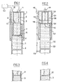
- Such a damper comprises a casing 1 in which a rod 2 slides.
- the casing is directly connected to the aircraft (most often by means of a hinge), and the rod carries to its bottom end the wheels of the aircraft.
- the damper contains hydraulic fluid (symbolized in the figures by horizontal lines) which, in the relaxed position of the damper shown here, completely fills the oil chamber 5 and the expansion chamber 7, and partially fills the chamber 6. The remaining volume of the latter is filled with nitrogen (symbolized in the figures by dots) under pressure.
- the rod 2 slides in the casing, which causes the transfer of hydraulic fluid from the oil chamber 5 to the air chamber 6 and the expansion chamber 7, via rolling orifices 15 which pass through the diaphragm 4.
- the level of hydraulic fluid in the air chamber 6 thus increases progressively as the damper is driven in.
- the damper is equipped with a first transmitter / receiver assembly 10 which is mounted at the upper end of the box 1 to emit a wave towards the upper end 13 of the rod 2.
- the transmitted wave After reflection on said upper end 13, the transmitted wave returns to the transmitter / receiver 10 to be received.
- An associated measuring member measures the time elapsed between the emission and the reception of the wave. This time is representative of the position of the upper end of the rod 2 in the casing 1, and therefore the depression of the damper.
- damping curve of the damper as a function of the load depends on several damping conditioning parameters, such as the initial nitrogen pressure (measured when the damper is expanded), and the fluid volume. hydraulic contained in the damper. If, due to leaks, nitrogen or hydraulic fluid escapes from the shock absorber, the actual damping of the shock may not correspond to the theoretical depression expected given the nominal conditioning.
- the shock absorber is equipped with a second transmitter / receiver assembly 11, also disposed at the upper end of the casing 1, for send a wave towards the rod 2 so that the wave reflects on the free surface 12 of the hydraulic fluid in the air chamber 6. After reflection on said free surface 12, the wave is received by the second set transmitter / receiver 11.
- An associated measuring device measures the time elapsed between transmission and reception of the wave. This time is representative of the actual level of hydraulic fluid in the air chamber 6.
- the aircraft is preferably equipped with a computer 50 adapted to calculate a theoretical level of hydraulic fluid in the damper from the measurement of the travel time of the wave emitted by the first transmitter / receiver assembly 10 to calculate a real level of hydraulic fluid in the damper from the measurement of the travel time of the wave emitted by the second transmitter / receiver unit 11, to compare these two levels, and to generate if necessary a setpoint maintenance to the pilot or ground maintenance crews.
- a computer 50 adapted to calculate a theoretical level of hydraulic fluid in the damper from the measurement of the travel time of the wave emitted by the first transmitter / receiver assembly 10 to calculate a real level of hydraulic fluid in the damper from the measurement of the travel time of the wave emitted by the second transmitter / receiver unit 11, to compare these two levels, and to generate if necessary a setpoint maintenance to the pilot or ground maintenance crews.
- the computer 50 may be external to the aircraft and be connected to the aircraft systems of the aircraft (by a cable connection or remotely) for example during a maintenance visit.
- the computer is arranged to cause the transmission of waves by the transmitter / receiver assemblies 10, 11, to exploit the travel times and check if the damper is properly conditioned.
- dampers are equipped with a separating piston 21 sliding freely inside the dip tube 3 and separating the nitrogen from the hydraulic fluid.
- the wave emitted by the second emitter / receiver unit 11 will then be reflected on said separator piston 21.
- the reflector 20 or the separating piston 21 are naturally movable and gradually sink into the damper as and when the rod 2 is pushed into the casing 1.
- the two transmitter / receiver assemblies 10 and 11 are arranged at the top of the box, which facilitates their electrical connection with the aircraft, and avoids the always tricky installation of cables running along the undercarriage.
- the invention also applies to an aircraft undercarriage equipped with an inverted damping device, such as that illustrated in FIG. figure 2 .
- This damper comprises a box 101, a rod 102, and a dip tube 103 carrying a diaphragm 104.
- the inverted damper also comprises an oil chamber 105 and an air chamber 106 in which hydraulic fluid from the chamber oil 105 is transferred via an orifice 115 formed in the diaphragm 104, during a depression of the damper.
- the air chamber 106 is no longer limited to the internal volume of the plunger tube, but is delimited laterally by the internal walls of the casing 106.
- the inverted damper further comprises an expansion chamber 107, but this is no longer arranged between the rod and the dip tube, but between the rod 102 and the casing 101.
- the expansion chamber 107 is this time powered by hydraulic fluid not by the oil chamber 105, but by the air chamber 106, via an orifice 116 formed in the upper bearing of the rod 102 which slides sealingly in the housing 101.
- the undercarriage is equipped with a first transmitter / receiver assembly 110, installed on the side of the box 101 to emit a wave towards an external reflector 113 associated with the rod 102. After reflection on said reflector 113, the wave is received by the transmitter / receiver assembly 110.
- An associated measuring device measures the time that has elapsed between the emission and the reception of the wave. This time is representative of the displacement of the reflector 113, therefore of the rod 102, and therefore the depression of the damper.
- the measured characteristic of the wave is the time elapsed between its emission and its reception, it will be possible to measure other characteristics of the wave, such as for example its reflection rate.
- each of the transmitter / receiver assemblies has been shown to be fully integrated in one and the same housing, the transmitter and receiver may be physically separated while forming a functional assembly. The path of the incident wave and the reflected wave may then not coincide.
Landscapes
- Engineering & Computer Science (AREA)
- General Engineering & Computer Science (AREA)
- Mechanical Engineering (AREA)
- Aviation & Aerospace Engineering (AREA)
- Vibration Prevention Devices (AREA)
- Measurement Of Mechanical Vibrations Or Ultrasonic Waves (AREA)
- Geophysics And Detection Of Objects (AREA)
- Testing Of Devices, Machine Parts, Or Other Structures Thereof (AREA)
Claims (4)
- Verfahren zur Kontrolle eines Füllstandes eines Hydraulikfluids in einem Stoßdämpfer, der einen ersten Abschnitt (1; 101) und einen zweiten Abschnitt (2; 102) umfasst, die zueinander verschiebbar sind, wobei das Verfahren die Schritte umfasst:- Aussenden einer ersten Welle, die dazu geeignet ist, sich ohne materielle Unterstützung auszubreiten, mit Hilfe eines ersten, an dem ersten beweglichen Abschnitt (1; 101) angeordneten Senders (10; 110) in Richtung des zweiten beweglichen Abschnittes (2; 102),- Empfangen der ersten ausgesandten Welle mit Hilfe eines ersten, an dem ersten beweglichen Abschnitt (1; 101) angeordneten Empfängers nach Reflexion der ausgesandten Welle an einem mechanischen Teil (13; 113), das fest mit dem zweiten beweglichen Abschnitt (2; 102) verbunden ist,- Herleiten eines theoretischen Füllstandes des Hydraulikfluids in dem Stoßdämpfer, welcher derjenige des Fluids in dem Stoßdämpfer in einem nominalen Konditionierungszustand des Stoßdämpfers wäre, ausgehend von einer Messung einer Eigenschaft der so empfangenen ersten Welle,- Aussenden einer zweiten Welle, die dazu geeignet ist, sich ohne materielle Unterstützung auszubreiten, mit Hilfe eines zweiten, an dem ersten beweglichen Abschnitt angeordneten Senders (11; 111) in Richtung des zweiten beweglichen Abschnittes,- Empfangen der zweiten ausgesandten Welle mit Hilfe eines zweiten, an dem ersten beweglichen Abschnitt angeordneten Empfängers nach Reflexion der ausgesandten Welle an einer freien Oberfläche (12; 112) des Hydraulikfluids oder an einem mechanischen Teil (20; 21), das diese freie Oberfläche begrenzt,- Herleiten eines tatsächlichen Füllstandes des Hydraulikfluids in dem Stoßdämpfer ausgehend von einer Messung einer Eigenschaft der so empfangenen zweiten Welle,- Vergleichen des tatsächlichen Füllstandes des Hydraulikfluids mit dem theoretischen Füllstand des Hydraulikfluids.
- Verfahren nach Anspruch 1, bei dem die Eigenschaft der Wellen, die gemessen wird, eine Zeitspanne ist, die zwischen dem Zeitpunkt, zu dem die Welle ausgesandt wird, und dem Zeitpunkt, zu dem die Welle empfangen wird, verstreicht.
- Flugzeug-Fahrwerk, umfassend einen Stoßdämpfer mit einem ersten Abschnitt (1; 101) und einem zweiten Abschnitt (2; 102), die zueinander verschiebbar sind, und
eine erste Sender/Empfänger-Einheit (10; 110) für Wellen, die an dem ersten beweglichen Abschnitt (1; 101) angeordnet ist, wobei der Sender so angeordnet ist, dass er eine erste Welle in Richtung des zweiten beweglichen Abschnittes (2; 102) aussendet, und der Empfänger dazu geeignet ist, die erste Welle nach deren Reflexion an einem Hindernis zu empfangen, das aus einem mechanischen Teil (13; 113) gebildet ist, das fest mit dem zweiten beweglichen Abschnitt (2; 102) verbunden ist, dadurch gekennzeichnet, dass das Fahrwerk ferner umfasst:- eine unabhängige zweite Sender/Empfänger-Einheit (11; 111), die an dem ersten beweglichen Abschnitt angeordnet ist, wobei der Sender derart angeordnet ist, dass er eine zweite Welle in Richtung des zweiten beweglichen Abschnitts aussendet, und der Empfänger dazu geeignet ist, die zweite Welle nach deren Reflexion an einem Hindernis zu empfangen, das aus einer freien Oberfläche (12; 112) eines in dem Stoßdämpfer enthaltenen Hydraulikfluids oder einem diese freie Oberfläche begrenzenden mechanischen Teil (20; 21) gebildet ist,- Rechenmittel (50) zum Bestimmen eines theoretischen Füllstandes des Hydraulikfluids in dem Stoßdämpfer ausgehend von der Messung einer Eigenschaft der ersten Welle und zum Bestimmen eines tatsächlichen Füllstandes des Hydraulikfluids in dem Stoßdämpfer ausgehend von der Messung einer Eigenschaft der zweiten Welle, wobei die genannten Mittel (50) derart ausgebildet sind, dass sie einen Vergleich zwischen dem theoretischen Füllstand des Fluids in dem Stoßdämpfer und dem tatsächlichen Füllstand des Fluids in dem Stoßdämpfer durchführen. - Fahrwerk nach Anspruch 3, wobei die Sender/Empfänger-Einheiten (10, 11; 110, 111) so an dem Fahrwerk angeordnet sind, dass der Weg der von den Sender/Empfänger-Einheiten ausgesandten Wellen vollständig im Inneren des Stoßdämpfers liegt.
Applications Claiming Priority (2)
| Application Number | Priority Date | Filing Date | Title |
|---|---|---|---|
| FR0404091 | 2004-04-19 | ||
| FR0404091A FR2869103B1 (fr) | 2004-04-19 | 2004-04-19 | Procede de mesure d'enfoncement d'un amortisseur, et atterrisseur d'aeronef faisant application |
Publications (3)
| Publication Number | Publication Date |
|---|---|
| EP1588872A2 EP1588872A2 (de) | 2005-10-26 |
| EP1588872A3 EP1588872A3 (de) | 2007-12-05 |
| EP1588872B1 true EP1588872B1 (de) | 2009-11-18 |
Family
ID=34942084
Family Applications (1)
| Application Number | Title | Priority Date | Filing Date |
|---|---|---|---|
| EP05290770A Expired - Lifetime EP1588872B1 (de) | 2004-04-19 | 2005-04-07 | Verfahren zur Messung des Eindrückens eines Stoßdämpfers und dessen Anwendung in einem Flugzeugfahrgestell |
Country Status (5)
| Country | Link |
|---|---|
| US (1) | US7454275B2 (de) |
| EP (1) | EP1588872B1 (de) |
| DE (1) | DE602005017697D1 (de) |
| ES (1) | ES2335506T3 (de) |
| FR (1) | FR2869103B1 (de) |
Cited By (1)
| Publication number | Priority date | Publication date | Assignee | Title |
|---|---|---|---|---|
| US11597249B2 (en) | 2018-09-18 | 2023-03-07 | Firestone Industrial Products Company, Llc | Internal damper sensors as well as damper assemblies and suspension systems including same |
Families Citing this family (4)
| Publication number | Priority date | Publication date | Assignee | Title |
|---|---|---|---|---|
| GB2496426B (en) | 2011-11-11 | 2013-12-25 | Messier Dowty Ltd | Gauge |
| WO2017184994A1 (en) * | 2016-04-22 | 2017-10-26 | KSR IP Holdings, LLC | Inductive sensor for shock absorber |
| EP3336485B1 (de) | 2016-12-15 | 2020-09-23 | Safran Landing Systems UK Limited | Flugzeuganordnung mit ablenkungssensor |
| CN107416189B (zh) * | 2017-07-26 | 2023-07-21 | 深圳市科卫泰实业发展有限公司 | 一种快速装配的飞行器起落架组件 |
Family Cites Families (5)
| Publication number | Priority date | Publication date | Assignee | Title |
|---|---|---|---|---|
| US4092947A (en) * | 1977-10-06 | 1978-06-06 | The United States Of America As Represented By The Secretary Of The Navy | Oil level indicator for use with damping fluid metering pins |
| US5104144A (en) * | 1990-09-25 | 1992-04-14 | Monroe Auto Equipment Company | Shock absorber with sonar position sensor |
| US5371598A (en) * | 1993-10-07 | 1994-12-06 | Motorola, Inc. | Optical displacement sensor and method for sensing linear displacements in a shock absorber |
| JPH1172132A (ja) * | 1997-06-25 | 1999-03-16 | Japan Radio Co Ltd | ばね上、ばね下構造体の相対挙動測定装置 |
| US7552803B2 (en) * | 2002-09-25 | 2009-06-30 | Goodrich Corporation | Aircraft shock strut having a fluid level monitor |
-
2004
- 2004-04-19 FR FR0404091A patent/FR2869103B1/fr not_active Expired - Fee Related
-
2005
- 2005-04-07 EP EP05290770A patent/EP1588872B1/de not_active Expired - Lifetime
- 2005-04-07 DE DE602005017697T patent/DE602005017697D1/de not_active Expired - Lifetime
- 2005-04-07 ES ES05290770T patent/ES2335506T3/es not_active Expired - Lifetime
- 2005-04-19 US US11/109,147 patent/US7454275B2/en not_active Expired - Lifetime
Cited By (2)
| Publication number | Priority date | Publication date | Assignee | Title |
|---|---|---|---|---|
| US11597249B2 (en) | 2018-09-18 | 2023-03-07 | Firestone Industrial Products Company, Llc | Internal damper sensors as well as damper assemblies and suspension systems including same |
| EP3853497B1 (de) * | 2018-09-18 | 2024-03-13 | Firestone Industrial Products Company, LLC | Interne dämpfersensoren sowie dämpferbaugruppen und aufhängungssysteme, die diese beinhalten |
Also Published As
| Publication number | Publication date |
|---|---|
| US20050230200A1 (en) | 2005-10-20 |
| ES2335506T3 (es) | 2010-03-29 |
| EP1588872A3 (de) | 2007-12-05 |
| FR2869103A1 (fr) | 2005-10-21 |
| DE602005017697D1 (de) | 2009-12-31 |
| US7454275B2 (en) | 2008-11-18 |
| FR2869103B1 (fr) | 2006-09-22 |
| EP1588872A2 (de) | 2005-10-26 |
Similar Documents
| Publication | Publication Date | Title |
|---|---|---|
| EP1571080A1 (de) | Aufhängevorrichtung eines Flugzeugtriebwerks an einem Flügelpylon | |
| CA2762767C (fr) | Amortisseur et atterrisseur equipe d'un tel amortisseur | |
| FR2928344A1 (fr) | Dispositif d'amortissement et systeme de rotor d'aerodyne l'incorporant | |
| FR2997151A1 (fr) | Amortisseur avec fonction ressort associee | |
| CA2936791C (fr) | Dispositif d'amortissement, et aeronef | |
| FR3010701A1 (fr) | Agencement d'un reservoir entre un capot de nacelle et une turbomachine | |
| EP1588872B1 (de) | Verfahren zur Messung des Eindrückens eines Stoßdämpfers und dessen Anwendung in einem Flugzeugfahrgestell | |
| CA2696709A1 (fr) | Nacelle de turboreacteur a amortisseurs pour demi-coquilles | |
| EP0117203B1 (de) | Dichtungsvorrichtung für hydraulischen telekopischen Energiedampfer | |
| FR2841954A1 (fr) | Ensemble de suspension pneumatique et de valve pour un systeme de suspension pneumatique combine a un amortisseur | |
| FR2809786A1 (fr) | Amortisseur d'oscillations a chambre annulaire de volume variable | |
| EP0173625A1 (de) | Flüssigkeitsbetätigte Einrichtung mit Spielkompensierung, insbesondere für Reibkupplungsmechanismus | |
| FR3141978A1 (fr) | Amortisseur hydraulique de suspension de véhicule automobile. | |
| FR2947485A1 (fr) | Moteur pivotant hydraulique | |
| EP0421826B1 (de) | Druckausgleichsvorrichtung eines untergetauchten Gasvolumens, insbesondere für einen untergetauchten Lautsprecher | |
| EP2317195A1 (de) | Keilschieber mit Druckausgleichssystem | |
| EP1431147B1 (de) | Bremspedal | |
| EP1978277B1 (de) | Ausgleichsmodul für einen Fahrzeughydraulikdämpfer und Dämpfer, der mit einem solchen Ausgleichsmodul ausgestattet ist | |
| FR3162817A1 (fr) | Vanne papillon de regulation d’un flux d’air comprenant un papillon double plaque | |
| FR3061087A1 (fr) | Dispositif hydraulique de reglage de garde au sol pour vehicule automobile et systeme de suspension et d'amortissement comprenant un tel dispositif | |
| FR3081146A1 (fr) | Systeme d'alimentation en air frais pour un sous-marin comportant un tel systeme | |
| WO2022229552A1 (fr) | Système d'étanchéité pour un dispositif d'accès à une infrastructure souterraine | |
| FR2962773A1 (fr) | Ensemble hydraulique a piston de section variable, pour une commande de debrayage | |
| FR3098266A1 (fr) | Amortisseur hydraulique télescopique multi-tarages | |
| EP1460243A1 (de) | Schalldämpfungsanlage |
Legal Events
| Date | Code | Title | Description |
|---|---|---|---|
| PUAI | Public reference made under article 153(3) epc to a published international application that has entered the european phase |
Free format text: ORIGINAL CODE: 0009012 |
|
| AK | Designated contracting states |
Kind code of ref document: A2 Designated state(s): AT BE BG CH CY CZ DE DK EE ES FI FR GB GR HU IE IS IT LI LT LU MC NL PL PT RO SE SI SK TR |
|
| AX | Request for extension of the european patent |
Extension state: AL BA HR LV MK YU |
|
| 17P | Request for examination filed |
Effective date: 20060327 |
|
| PUAL | Search report despatched |
Free format text: ORIGINAL CODE: 0009013 |
|
| AK | Designated contracting states |
Kind code of ref document: A3 Designated state(s): AT BE BG CH CY CZ DE DK EE ES FI FR GB GR HU IE IS IT LI LT LU MC NL PL PT RO SE SI SK TR |
|
| AX | Request for extension of the european patent |
Extension state: AL BA HR LV MK YU |
|
| 17Q | First examination report despatched |
Effective date: 20080131 |
|
| AKX | Designation fees paid |
Designated state(s): DE ES FR GB IT |
|
| GRAP | Despatch of communication of intention to grant a patent |
Free format text: ORIGINAL CODE: EPIDOSNIGR1 |
|
| RIC1 | Information provided on ipc code assigned before grant |
Ipc: F16F 9/00 20060101ALI20090513BHEP Ipc: G01F 23/296 20060101ALI20090513BHEP Ipc: G01B 11/14 20060101ALI20090513BHEP Ipc: B60G 17/00 20060101AFI20090513BHEP Ipc: G01B 17/00 20060101ALI20090513BHEP Ipc: G01B 7/14 20060101ALI20090513BHEP |
|
| GRAS | Grant fee paid |
Free format text: ORIGINAL CODE: EPIDOSNIGR3 |
|
| GRAA | (expected) grant |
Free format text: ORIGINAL CODE: 0009210 |
|
| AK | Designated contracting states |
Kind code of ref document: B1 Designated state(s): DE ES FR GB IT |
|
| REG | Reference to a national code |
Ref country code: GB Ref legal event code: FG4D Free format text: NOT ENGLISH |
|
| REF | Corresponds to: |
Ref document number: 602005017697 Country of ref document: DE Date of ref document: 20091231 Kind code of ref document: P |
|
| REG | Reference to a national code |
Ref country code: ES Ref legal event code: FG2A Ref document number: 2335506 Country of ref document: ES Kind code of ref document: T3 |
|
| PLBE | No opposition filed within time limit |
Free format text: ORIGINAL CODE: 0009261 |
|
| STAA | Information on the status of an ep patent application or granted ep patent |
Free format text: STATUS: NO OPPOSITION FILED WITHIN TIME LIMIT |
|
| 26N | No opposition filed |
Effective date: 20100819 |
|
| REG | Reference to a national code |
Ref country code: DE Ref legal event code: R082 Ref document number: 602005017697 Country of ref document: DE Representative=s name: SCHAUMBURG, THOENES, THURN, LANDSKRON, ECKERT, DE |
|
| REG | Reference to a national code |
Ref country code: DE Ref legal event code: R081 Ref document number: 602005017697 Country of ref document: DE Owner name: MESSIER-BUGATTI-DOWTY, FR Free format text: FORMER OWNER: MESSIER-DOWTY S.A., VELIZY VILLACOUBLAY, FR Effective date: 20110711 Ref country code: DE Ref legal event code: R082 Ref document number: 602005017697 Country of ref document: DE Representative=s name: PATENTANWAELTE SCHAUMBURG, THOENES, THURN, LAN, DE Effective date: 20110711 Ref country code: DE Ref legal event code: R081 Ref document number: 602005017697 Country of ref document: DE Owner name: MESSIER-BUGATTI-DOWTY, FR Free format text: FORMER OWNER: MESSIER-BUGATTI-DOWTY, VELIZY VILLACOUBLAY, FR Effective date: 20110711 Ref country code: DE Ref legal event code: R082 Ref document number: 602005017697 Country of ref document: DE Representative=s name: SCHAUMBURG & PARTNER PATENTANWAELTE GBR, DE Effective date: 20110711 Ref country code: DE Ref legal event code: R082 Ref document number: 602005017697 Country of ref document: DE Representative=s name: SCHAUMBURG UND PARTNER PATENTANWAELTE MBB, DE Effective date: 20110711 |
|
| REG | Reference to a national code |
Ref country code: GB Ref legal event code: 732E Free format text: REGISTERED BETWEEN 20110901 AND 20110907 |
|
| REG | Reference to a national code |
Ref country code: FR Ref legal event code: TP Owner name: MESSIER-BUGATTI-DOWTY, FR Effective date: 20110922 |
|
| REG | Reference to a national code |
Ref country code: ES Ref legal event code: PC2A Owner name: MESSIER-BUGATTI-DOWTY Effective date: 20120113 |
|
| PGFP | Annual fee paid to national office [announced via postgrant information from national office to epo] |
Ref country code: IT Payment date: 20120321 Year of fee payment: 8 |
|
| PGFP | Annual fee paid to national office [announced via postgrant information from national office to epo] |
Ref country code: ES Payment date: 20120410 Year of fee payment: 8 |
|
| PG25 | Lapsed in a contracting state [announced via postgrant information from national office to epo] |
Ref country code: IT Free format text: LAPSE BECAUSE OF NON-PAYMENT OF DUE FEES Effective date: 20140407 |
|
| REG | Reference to a national code |
Ref country code: DE Ref legal event code: R082 Ref document number: 602005017697 Country of ref document: DE Representative=s name: SCHAUMBURG & PARTNER PATENTANWAELTE GBR, DE Ref country code: DE Ref legal event code: R082 Ref document number: 602005017697 Country of ref document: DE Representative=s name: SCHAUMBURG UND PARTNER PATENTANWAELTE MBB, DE |
|
| REG | Reference to a national code |
Ref country code: ES Ref legal event code: FD2A Effective date: 20150527 |
|
| PG25 | Lapsed in a contracting state [announced via postgrant information from national office to epo] |
Ref country code: ES Free format text: LAPSE BECAUSE OF NON-PAYMENT OF DUE FEES Effective date: 20140408 |
|
| REG | Reference to a national code |
Ref country code: FR Ref legal event code: PLFP Year of fee payment: 12 |
|
| REG | Reference to a national code |
Ref country code: FR Ref legal event code: PLFP Year of fee payment: 13 |
|
| REG | Reference to a national code |
Ref country code: FR Ref legal event code: CD Owner name: MESSIER-BUGATTI-DOWTY, FR Effective date: 20170518 |
|
| REG | Reference to a national code |
Ref country code: FR Ref legal event code: PLFP Year of fee payment: 14 |
|
| PGFP | Annual fee paid to national office [announced via postgrant information from national office to epo] |
Ref country code: GB Payment date: 20240320 Year of fee payment: 20 |
|
| PGFP | Annual fee paid to national office [announced via postgrant information from national office to epo] |
Ref country code: FR Payment date: 20240320 Year of fee payment: 20 |
|
| PGFP | Annual fee paid to national office [announced via postgrant information from national office to epo] |
Ref country code: DE Payment date: 20240320 Year of fee payment: 20 |
|
| REG | Reference to a national code |
Ref country code: DE Ref legal event code: R071 Ref document number: 602005017697 Country of ref document: DE |
|
| REG | Reference to a national code |
Ref country code: GB Ref legal event code: PE20 Expiry date: 20250406 |
|
| PG25 | Lapsed in a contracting state [announced via postgrant information from national office to epo] |
Ref country code: GB Free format text: LAPSE BECAUSE OF EXPIRATION OF PROTECTION Effective date: 20250406 |