EP1588872B1 - Method of measurement of the depression of a shock absorber and its use in an aircraft undercarriage - Google Patents
Method of measurement of the depression of a shock absorber and its use in an aircraft undercarriage Download PDFInfo
- Publication number
- EP1588872B1 EP1588872B1 EP05290770A EP05290770A EP1588872B1 EP 1588872 B1 EP1588872 B1 EP 1588872B1 EP 05290770 A EP05290770 A EP 05290770A EP 05290770 A EP05290770 A EP 05290770A EP 1588872 B1 EP1588872 B1 EP 1588872B1
- Authority
- EP
- European Patent Office
- Prior art keywords
- wave
- hydraulic fluid
- movable portion
- shock absorber
- level
- Prior art date
- Legal status (The legal status is an assumption and is not a legal conclusion. Google has not performed a legal analysis and makes no representation as to the accuracy of the status listed.)
- Expired - Lifetime
Links
Images
Classifications
-
- F—MECHANICAL ENGINEERING; LIGHTING; HEATING; WEAPONS; BLASTING
- F16—ENGINEERING ELEMENTS AND UNITS; GENERAL MEASURES FOR PRODUCING AND MAINTAINING EFFECTIVE FUNCTIONING OF MACHINES OR INSTALLATIONS; THERMAL INSULATION IN GENERAL
- F16F—SPRINGS; SHOCK-ABSORBERS; MEANS FOR DAMPING VIBRATION
- F16F9/00—Springs, vibration-dampers, shock-absorbers, or similarly-constructed movement-dampers using a fluid or the equivalent as damping medium
- F16F9/32—Details
- F16F9/3264—Arrangements for indicating, e.g. fluid level; Arrangements for checking dampers
-
- B—PERFORMING OPERATIONS; TRANSPORTING
- B64—AIRCRAFT; AVIATION; COSMONAUTICS
- B64C—AEROPLANES; HELICOPTERS
- B64C25/00—Alighting gear
- B64C25/32—Alighting gear characterised by elements which contact the ground or similar surface
- B64C25/58—Arrangements or adaptations of shock-absorbers or springs
- B64C25/60—Oleo legs
-
- F—MECHANICAL ENGINEERING; LIGHTING; HEATING; WEAPONS; BLASTING
- F16—ENGINEERING ELEMENTS AND UNITS; GENERAL MEASURES FOR PRODUCING AND MAINTAINING EFFECTIVE FUNCTIONING OF MACHINES OR INSTALLATIONS; THERMAL INSULATION IN GENERAL
- F16F—SPRINGS; SHOCK-ABSORBERS; MEANS FOR DAMPING VIBRATION
- F16F2230/00—Purpose; Design features
- F16F2230/08—Sensor arrangement
Definitions
- the invention relates to a method for measuring a theoretical level of hydraulic fluid in a damper, and an aircraft lander making application.
- a damper comprising a damper having a first portion and a second portion movable between them slidably, the damper being equipped with a wave transmitter / receiver assembly disposed on the first movable portion, the transmitter being arranged to emit the wave towards the second moving part; and the receiver being adapted to receive the wave after reflection thereof on an obstacle formed by a mechanical part integral with the second mobile part.
- the damper is equipped with a transmitter / receiver assembly adapted to send a wave on an obstacle formed by a free surface of a hydraulic fluid contained in the damper or a mechanical part defining this free surface.
- the invention relates to a measurement method for determining a theoretical level of hydraulic fluid in the damper and is defined in the main claims.
- the measurement makes it possible to determine a depression of the damper, and, by exploiting the relation between depression and theoretical level of hydraulic fluid or by using tables, it is possible to deduce the theoretical level of hydraulic fluid that should correspond to the depression if the shock absorber is properly conditioned.
- the actual level of hydraulic fluid is then determined in a manner similar to the damming of the damper by two transmitting / receiving units operating in parallel.
- the two sets determine two different parameters well: the first set makes it possible to determine a theoretical level of hydraulic fluid, whereas the second set makes it possible to determine a real level of hydraulic fluid.
- the method of the invention comprises the step of comparing the actual level of hydraulic fluid to the theoretical level of hydraulic fluid. This comparison makes it possible to deduce information on the conditioning of the damper.
- the invention also relates to an aircraft undercarriage comprising a shock absorber with a first part and a second part movably movable together, comprising a first wave transmitter / receiver assembly disposed on the first movable part, the transmitter being arranged for emitting a first wave towards the second mobile part, and the receiver being able to receive the first wave after reflection thereof on an obstacle formed by a mechanical part integral with the second mobile part, and a second transmitter / receiver assembly independent device disposed on the first mobile part, the transmitter being arranged to emit a second wave towards the second mobile part, and the receiver being able to receive the second wave after reflection thereof on an obstacle formed by a free surface of the hydraulic fluid contained in the damper or a mechanical part defining this free surface.
- the transmitter / receiver assemblies are arranged on the landing gear so that the path of the waves emitted by the transmitter / receiver assemblies is entirely internal to the damper.
- the invention applies to an undercarriage equipped with a so-called conventional shock absorber, also well known.
- Such a damper comprises a casing 1 in which a rod 2 slides.
- the casing is directly connected to the aircraft (most often by means of a hinge), and the rod carries to its bottom end the wheels of the aircraft.
- the damper contains hydraulic fluid (symbolized in the figures by horizontal lines) which, in the relaxed position of the damper shown here, completely fills the oil chamber 5 and the expansion chamber 7, and partially fills the chamber 6. The remaining volume of the latter is filled with nitrogen (symbolized in the figures by dots) under pressure.
- the rod 2 slides in the casing, which causes the transfer of hydraulic fluid from the oil chamber 5 to the air chamber 6 and the expansion chamber 7, via rolling orifices 15 which pass through the diaphragm 4.
- the level of hydraulic fluid in the air chamber 6 thus increases progressively as the damper is driven in.
- the damper is equipped with a first transmitter / receiver assembly 10 which is mounted at the upper end of the box 1 to emit a wave towards the upper end 13 of the rod 2.
- the transmitted wave After reflection on said upper end 13, the transmitted wave returns to the transmitter / receiver 10 to be received.
- An associated measuring member measures the time elapsed between the emission and the reception of the wave. This time is representative of the position of the upper end of the rod 2 in the casing 1, and therefore the depression of the damper.
- damping curve of the damper as a function of the load depends on several damping conditioning parameters, such as the initial nitrogen pressure (measured when the damper is expanded), and the fluid volume. hydraulic contained in the damper. If, due to leaks, nitrogen or hydraulic fluid escapes from the shock absorber, the actual damping of the shock may not correspond to the theoretical depression expected given the nominal conditioning.
- the shock absorber is equipped with a second transmitter / receiver assembly 11, also disposed at the upper end of the casing 1, for send a wave towards the rod 2 so that the wave reflects on the free surface 12 of the hydraulic fluid in the air chamber 6. After reflection on said free surface 12, the wave is received by the second set transmitter / receiver 11.
- An associated measuring device measures the time elapsed between transmission and reception of the wave. This time is representative of the actual level of hydraulic fluid in the air chamber 6.
- the aircraft is preferably equipped with a computer 50 adapted to calculate a theoretical level of hydraulic fluid in the damper from the measurement of the travel time of the wave emitted by the first transmitter / receiver assembly 10 to calculate a real level of hydraulic fluid in the damper from the measurement of the travel time of the wave emitted by the second transmitter / receiver unit 11, to compare these two levels, and to generate if necessary a setpoint maintenance to the pilot or ground maintenance crews.
- a computer 50 adapted to calculate a theoretical level of hydraulic fluid in the damper from the measurement of the travel time of the wave emitted by the first transmitter / receiver assembly 10 to calculate a real level of hydraulic fluid in the damper from the measurement of the travel time of the wave emitted by the second transmitter / receiver unit 11, to compare these two levels, and to generate if necessary a setpoint maintenance to the pilot or ground maintenance crews.
- the computer 50 may be external to the aircraft and be connected to the aircraft systems of the aircraft (by a cable connection or remotely) for example during a maintenance visit.
- the computer is arranged to cause the transmission of waves by the transmitter / receiver assemblies 10, 11, to exploit the travel times and check if the damper is properly conditioned.
- dampers are equipped with a separating piston 21 sliding freely inside the dip tube 3 and separating the nitrogen from the hydraulic fluid.
- the wave emitted by the second emitter / receiver unit 11 will then be reflected on said separator piston 21.
- the reflector 20 or the separating piston 21 are naturally movable and gradually sink into the damper as and when the rod 2 is pushed into the casing 1.
- the two transmitter / receiver assemblies 10 and 11 are arranged at the top of the box, which facilitates their electrical connection with the aircraft, and avoids the always tricky installation of cables running along the undercarriage.
- the invention also applies to an aircraft undercarriage equipped with an inverted damping device, such as that illustrated in FIG. figure 2 .
- This damper comprises a box 101, a rod 102, and a dip tube 103 carrying a diaphragm 104.
- the inverted damper also comprises an oil chamber 105 and an air chamber 106 in which hydraulic fluid from the chamber oil 105 is transferred via an orifice 115 formed in the diaphragm 104, during a depression of the damper.
- the air chamber 106 is no longer limited to the internal volume of the plunger tube, but is delimited laterally by the internal walls of the casing 106.
- the inverted damper further comprises an expansion chamber 107, but this is no longer arranged between the rod and the dip tube, but between the rod 102 and the casing 101.
- the expansion chamber 107 is this time powered by hydraulic fluid not by the oil chamber 105, but by the air chamber 106, via an orifice 116 formed in the upper bearing of the rod 102 which slides sealingly in the housing 101.
- the undercarriage is equipped with a first transmitter / receiver assembly 110, installed on the side of the box 101 to emit a wave towards an external reflector 113 associated with the rod 102. After reflection on said reflector 113, the wave is received by the transmitter / receiver assembly 110.
- An associated measuring device measures the time that has elapsed between the emission and the reception of the wave. This time is representative of the displacement of the reflector 113, therefore of the rod 102, and therefore the depression of the damper.
- the measured characteristic of the wave is the time elapsed between its emission and its reception, it will be possible to measure other characteristics of the wave, such as for example its reflection rate.
- each of the transmitter / receiver assemblies has been shown to be fully integrated in one and the same housing, the transmitter and receiver may be physically separated while forming a functional assembly. The path of the incident wave and the reflected wave may then not coincide.
Landscapes
- Engineering & Computer Science (AREA)
- General Engineering & Computer Science (AREA)
- Mechanical Engineering (AREA)
- Aviation & Aerospace Engineering (AREA)
- Vibration Prevention Devices (AREA)
- Measurement Of Mechanical Vibrations Or Ultrasonic Waves (AREA)
- Geophysics And Detection Of Objects (AREA)
- Testing Of Devices, Machine Parts, Or Other Structures Thereof (AREA)
Description
L'invention concerne un procédé de mesure d'un niveau théorique de fluide hydraulique dans un amortisseur, ainsi qu'un atterrisseur d'aéronef faisant application.The invention relates to a method for measuring a theoretical level of hydraulic fluid in a damper, and an aircraft lander making application.
On connaît, du document
En mesurant le temps de trajet de l'onde, on en déduit un enfoncement de l'amortisseur.By measuring the travel time of the wave, we deduce a depression of the damper.
Dans une variante mentionnée dans ce même document, l'amortisseur est équipé d'un ensemble émetteur/récepteur adapté à envoyer une onde sur un obstacle formé par une surface libre d'un fluide hydraulique contenu dans l'amortisseur ou une pièce mécanique délimitant cette surface libre.In a variant mentioned in this same document, the damper is equipped with a transmitter / receiver assembly adapted to send a wave on an obstacle formed by a free surface of a hydraulic fluid contained in the damper or a mechanical part defining this free surface.
En mesurant le temps de trajet de l'onde, on en déduit un niveau réel de fluide hydraulique dans l'amortisseur. En connaissant la relation entre le niveau théorique de fluide hydraulique dans l'amortisseur et son enfoncement, on en déduit un enfoncement de l'amortisseur.By measuring the travel time of the wave, we deduce a real level of hydraulic fluid in the damper. Knowing the relationship between the theoretical level of hydraulic fluid in the damper and its depression, one deduces a depression of the damper.
Cependant, l'application de cette méthode suppose que l'amortisseur ait été correctement conditionné et n'ait pas subi de fuites de fluide hydraulique, de sorte que le niveau théorique de fluide hydraulique et le niveau réel de fluide hydraulique coïncident.However, the application of this method assumes that the damper has been properly conditioned and has not suffered hydraulic fluid leakage, so that the theoretical level of hydraulic fluid and the actual level of hydraulic fluid coincide.
Si une quantité incorrecte de fluide hydraulique a été introduite dans l'amortisseur ou si l'amortisseur a subi des fuites, alors le niveau réel de fluide hydraulique peut être différent du niveau théorique de fluide hydraulique, de sorte que l'on en déduit un mauvais enfoncement.If an incorrect amount of hydraulic fluid has been introduced into the damper or if the damper has leaks, then the actual level of hydraulic fluid may be different from the theoretical level of hydraulic fluid, so that we can deduce a bad depression.
L'invention a pour objet un procédé de mesure permettant de déterminer un niveau théorique de fluide hydraulique dans l'amortisseur et elle est défini dans les revendications principales.The invention relates to a measurement method for determining a theoretical level of hydraulic fluid in the damper and is defined in the main claims.
Le procédé de mesure de l'enfoncement d'un amortisseur comprenant une première et une deuxième parties mobiles entre elles à coulissement,' comporte, selon l'invention, les étapes de :
- émettre une onde apte à se propager sans support matériel à l'aide d'un émetteur disposé sur la première partie mobile en direction de la deuxième partie mobile;
- recevoir l'onde émise à l'aide d'un récepteur disposé sur la première partie mobile, après réflexion de l'onde émise sur un obstacle mobile solidaire de la deuxième partie mobile ;
- déduire un niveau théorique de fluide hydraulique à partir d'une mesure d'une caractéristique de l'onde ainsi reçue.
- emitting a wave capable of propagating without physical support by means of an emitter disposed on the first moving part in the direction of the second mobile part;
- receiving the transmitted wave with the aid of a receiver disposed on the first mobile part, after reflection of the wave emitted on a mobile obstacle secured to the second mobile part;
- deduce a theoretical level of hydraulic fluid from a measurement of a characteristic of the wave thus received.
La mesure permet de déterminer un enfoncement de l'amortisseur, et, en exploitant la relation entre enfoncement et niveau théorique de fluide hydraulique ou encore en utilisant des tables, on en déduit le niveau théorique de fluide hydraulique qui devrait correspondre à l'enfoncement si l'amortisseur est correctement conditionné.The measurement makes it possible to determine a depression of the damper, and, by exploiting the relation between depression and theoretical level of hydraulic fluid or by using tables, it is possible to deduce the theoretical level of hydraulic fluid that should correspond to the depression if the shock absorber is properly conditioned.
Le procédé de l'invention comporte en outre les étapes de :
- émettre une deuxième onde apte à se propager sans support matériel à l'aide d'un deuxième émetteur disposé sur la première partie mobile en direction de la deuxième partie mobile ;
- recevoir l'onde émise à l'aide d'un deuxième récepteur disposé sur la première partie mobile après réflexion de l'onde émise sur une surface libre du fluide hydraulique ou sur une pièce mécanique délimitant cette surface libre ;
- déduire un niveau réel de fluide hydraulique de la mesure d'une caractéristique de l'onde ainsi reçue.
- to emit a second wave able to propagate without any material support by means of a second transmitter disposed on the first movable part in the direction of the second moving part;
- receiving the transmitted wave with the aid of a second receiver disposed on the first moving part after reflection of the wave emitted on a free surface of the hydraulic fluid or on a mechanical part delimiting this free surface;
- deduce a real level of hydraulic fluid from the measurement of a characteristic of the wave thus received.
Le niveau réel de fluide hydraulique est alors déterminé de façon similaire à l'enfoncement de l'amortisseur par deux ensembles émetteur/récepteur fonctionnant parallèlement.The actual level of hydraulic fluid is then determined in a manner similar to the damming of the damper by two transmitting / receiving units operating in parallel.
On remarquera que les deux ensembles déterminent bien deux paramètres différents : le premier ensemble permet de déterminer un niveau théorique de fluide hydraulique, tandis que le deuxième ensemble permet de déterminer un niveau réel de fluide hydraulique.It will be noted that the two sets determine two different parameters well: the first set makes it possible to determine a theoretical level of hydraulic fluid, whereas the second set makes it possible to determine a real level of hydraulic fluid.
Le procédé de l'invention comporte l'étape de comparer le niveau réel de fluide hydraulique au niveau théorique de fluide hydraulique. Cette comparaison permet d'en déduire une information sur le conditionnement de l'amortisseur.The method of the invention comprises the step of comparing the actual level of hydraulic fluid to the theoretical level of hydraulic fluid. This comparison makes it possible to deduce information on the conditioning of the damper.
L'invention concerne également un atterrisseur d'aéronef comportant un amortisseur avec une première partie et une deuxième partie mobiles entre elles à coulissement, comportant un premier ensemble émetteur/récepteur d'onde disposé sur la première partie mobile, l'émetteur étant disposé pour émettre une première onde en direction de la deuxième partie mobile, et le récepteur étant apte à recevoir la première onde après réflexion de celle-ci sur un obstacle formé par une pièce mécanique solidaire de la deuxième partie mobile, et un deuxième ensemble émetteur/récepteur indépendant disposé sur la première partie mobile, l'émetteur étant disposé pour émettre une deuxième onde en direction de la deuxième partie mobile, et le récepteur étant apte à recevoir la deuxième onde après réflexion de celle-ci sur un obstacle formé par une surface libre du fluide hydraulique contenu dans l'amortisseur ou une pièce mécanique délimitant cette surface libre.The invention also relates to an aircraft undercarriage comprising a shock absorber with a first part and a second part movably movable together, comprising a first wave transmitter / receiver assembly disposed on the first movable part, the transmitter being arranged for emitting a first wave towards the second mobile part, and the receiver being able to receive the first wave after reflection thereof on an obstacle formed by a mechanical part integral with the second mobile part, and a second transmitter / receiver assembly independent device disposed on the first mobile part, the transmitter being arranged to emit a second wave towards the second mobile part, and the receiver being able to receive the second wave after reflection thereof on an obstacle formed by a free surface of the hydraulic fluid contained in the damper or a mechanical part defining this free surface.
Avantageusement, les ensembles émetteur/récepteur sont disposés sur l'atterrisseur de telle sorte que le cheminement des ondes émises par les ensembles émetteur/récepteur soit en totalité interne à l'amortisseur.Advantageously, the transmitter / receiver assemblies are arranged on the landing gear so that the path of the waves emitted by the transmitter / receiver assemblies is entirely internal to the damper.
L'invention sera mieux comprise à la lumière de la description qui suit en référence aux figures des dessins annexés parmi lesquelles :
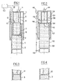
- la
figure 1 est une vue en coupe partielle d'un atterrisseur d'aéronef selon l'invention ; - la
figure 2 est une vue en coupe partielle d'un autre atterrisseur d'aéronef selon l'invention ; - la
figure 3 est une vue en coupe partielle d'un amortisseur d'aéronef équipé d'un piston séparateur ; - la
figure 4 est une vue en coupe partielle d'un amortisseur d'aéronef équipé d'un réflecteur flottant.
- the
figure 1 is a partial sectional view of an aircraft undercarriage according to the invention; - the
figure 2 is a partial sectional view of another aircraft undercarriage according to the invention; - the
figure 3 is a partial sectional view of an aircraft damper equipped with a separator piston; - the
figure 4 is a partial sectional view of an aircraft damper equipped with a floating reflector.
Comme cela est illustré à la
Un tel amortisseur comporte un caisson 1 dans lequel coulisse une tige 2. Dans le cas d'un atterrisseur direct, le caisson est directement relié à l'aéronef (le plus souvent au moyen d'une articulation), et la tige porte à son extrémité inférieure les roues de l'aéronef.Such a damper comprises a casing 1 in which a
Dans la tige 2 s'étend un tube plongeur 3 terminé par un diaphragme 4. L'amortisseur ainsi constitué comporte trois chambres fonctionnelles :
- une première chambre dite chambre d'huile 5, qui s'étend dans la
tige 2 est qui est fermée par le diaphragme 4 ; - une deuxième chambre dite chambre d'air 6, qui correspond au volume interne du
tube plongeur 3 ; - une troisième chambre annulaire dite chambre de
détente 7, qui s'étend entre latige 2 et letube plongeur 3.
- a first chamber called
oil chamber 5, which extends in therod 2 is closed by the diaphragm 4; - a second chamber called
air chamber 6, which corresponds to the internal volume of theplunger tube 3; - a third annular chamber called
expansion chamber 7, which extends between therod 2 and thedip tube 3.
L'amortisseur contient du fluide hydraulique (symbolisé sur les figures par des traits horizontaux) qui, dans la position détendue de l'amortisseur représentée ici, remplit entièrement la chambre d'huile 5 et la chambre de détente 7, et remplit partiellement la chambre d'air 6. Le volume restant de cette dernière est rempli d'azote (symbolisé sur les figures par des points) sous pression.The damper contains hydraulic fluid (symbolized in the figures by horizontal lines) which, in the relaxed position of the damper shown here, completely fills the
Lors d'un enfoncement de l'amortisseur (par exemple lors d'un atterrissage), la tige 2 coulisse dans le caisson, ce qui provoque le transfert de fluide hydraulique depuis la chambre d'huile 5 vers la chambre d'air 6 et la chambre de détente 7, via des orifices de laminage 15 qui traversent le diaphragme 4. Le niveau de fluide hydraulique dans la chambre d'air 6 augmente ainsi progressivement au fur et à mesure de l'enfoncement de l'amortisseur.During a depression of the damper (for example during a landing), the
Selon l'invention, l'amortisseur est équipé d'une premier ensemble émetteur/récepteur 10 qui est monté à l'extrémité supérieure du caisson 1 pour émettre une onde en direction de l'extrémité supérieure 13 de la tige 2.According to the invention, the damper is equipped with a first transmitter /
Après réflexion sur ladite extrémité supérieure 13, l'onde émise revient vers l'ensemble émetteur/récepteur 10 pour être reçue. Un organe de mesure associé (l'organe de mesure pouvant ou non être intégré dans ledit ensemble) mesure le temps écoulé entre l'émission et la réception de l'onde. Ce temps est représentatif de la position de l'extrémité supérieure de la tige 2 dans le caisson 1, et donc de l'enfoncement de l'amortisseur.After reflection on said
On obtient ainsi une mesure en temps réel de l'enfoncement, qui ne fait appel à aucun support spécifique de propagation puisque l'onde se propage tout simplement dans l'air.We obtain a real-time measurement of the depression, which does not use any specific support of propagation since the wave propagates itself simply in the air.
Il est à remarquer que l'onde se propage ici dans une partie interne du caisson à l'abri des pollutions extérieures.It should be noted that the wave propagates here in an internal part of the box protected from external pollution.
On sait que la courbe d'enfoncement de l'amortisseur en fonction de la charge dépend de plusieurs paramètres de conditionnement de l'amortisseur, comme la pression initiale d'azote (mesurée lorsque l'amortisseur est détendu), et le volume de fluide hydraulique contenu dans l'amortisseur. Si, en raison de fuites, de l'azote ou du fluide hydraulique s'échappe de l'amortisseur, il se peut que l'enfoncement réel de l'amortisseur ne corresponde pas à l'enfoncement théorique attendu compte tenu du conditionnement nominal.It is known that the damping curve of the damper as a function of the load depends on several damping conditioning parameters, such as the initial nitrogen pressure (measured when the damper is expanded), and the fluid volume. hydraulic contained in the damper. If, due to leaks, nitrogen or hydraulic fluid escapes from the shock absorber, the actual damping of the shock may not correspond to the theoretical depression expected given the nominal conditioning.
L'invention permet de vérifier à tout moment l'état de conditionnement de l'amortisseur par le moyen suivant : on équipe l'amortisseur d'un deuxième ensemble émetteur/récepteur 11, également disposé à l'extrémité supérieure du caisson 1, pour envoyer une onde en direction de la tige 2 de sorte que l'onde de réfléchisse sur la surface libre 12 du fluide hydraulique dans la chambre d'air 6. Après réflexion sur ladite surface libre 12, l'onde est reçue par le deuxième ensemble émetteur/récepteur 11. Un organe de mesure associé (l'organe de mesure pouvant ou non être intégré dans ledit ensemble) mesure le temps écoulé entre l'émission et la réception de l'onde. Ce temps est représentatif du niveau réel de fluide hydraulique dans la chambre d'air 6.The invention makes it possible to check at any time the conditioning condition of the shock absorber by the following means: the shock absorber is equipped with a second transmitter /
Il est alors aisé de comparer ce niveau réel à un niveau théorique calculé à partir de la mesure de l'enfoncement de l'amortisseur obtenue au moyen du premier ensemble émetteur/récepteur 10, compte tenu des paramètres de conditionnement nominaux. Si le niveau réel ne correspond pas au niveau théorique, à une marge d'erreur prédéterminée près, alors on en déduit que l'amortisseur est mal conditionné ou que des fuites se sont produites. Il est alors possible de générer automatiquement une consigne de maintenance à destination du pilote de l'aéronef, ou des équipes de maintenance au sol.It is then easy to compare this actual level to a theoretical level calculated from the measurement of the depression of the damper obtained by means of the first transmitter /
Pour cela, l'aéronef est de préférence équipé d'un calculateur 50 adapté à calculer un niveau théorique de fluide hydraulique dans l'amortisseur à partir de la mesure du temps de parcours de l'onde émise par le premier ensemble émetteur/récepteur 10, à calculer un niveau réel de fluide hydraulique dans l'amortisseur à partir de la mesure du temps de parcours de l'onde émise par le deuxième ensemble émetteur/récepteur 11, à comparer ces deux niveaux, et à générer le cas échéant une consigne de maintenance à destination du pilote ou des équipes de maintenance au sol.For this, the aircraft is preferably equipped with a
En variante, le calculateur 50 peut être externe à l'aéronef et être connecté aux systèmes de bord de l'aéronef (par une liaison par câble ou encore à distance) par exemple à l'occasion d'une visite de maintenance. Le calculateur est agencé pour provoquer l'émission d'ondes par les ensembles émetteur/récepteur 10,11, pour en exploiter les temps de parcours et vérifier si l'amortisseur est correctement conditionné.Alternatively, the
Comme cela est illustré à la
Pour améliorer la réflexion de l'onde émise par le deuxième ensemble émetteur/récepteur 11, il est possible, comme cela est illustré à la
Le réflecteur 20 ou le piston séparateur 21 sont naturellement mobiles et s'enfoncent progressivement dans l'amortisseur au fur et à mesure de l'enfoncement de la tige 2 dans le caisson 1.The
On remarquera que les deux ensembles émetteur/récepteur 10 et 11 sont disposés en haut du caisson, ce qui facilite leur liaison électrique avec l'aéronef, et évite l'installation toujours délicate de câbles courant le long de l'atterrisseur.Note that the two transmitter /
L'invention s'applique également à un atterrisseur d'aéronef équipé d'un amortisseur dit inversé, tel que celui illustré à la
L'amortisseur inversé comporte en outre une chambre de détente 107, mais celle-ci n'est plus agencée entre la tige et le tube plongeur, mais entre la tige 102 et le caisson 101. La chambre de détente 107 est cette fois alimentée en fluide hydraulique non pas par la chambre d'huile 105, mais par la chambre d'air 106, via un orifice 116 ménagé dans le palier supérieur de la tige 102 qui coulisse à étanchéité dans le caisson 101.The inverted damper further comprises an
L'atterrisseur est équipé d'un premier ensemble émetteur/récepteur 110, installé sur le côté du caisson 101 pour émettre une onde en direction d'un réflecteur externe 113 associé à la tige 102. Après réflexion sur ledit réflecteur 113, l'onde est reçue par l'ensemble émetteur/récepteur 110. Un organe de mesure associé mesure le temps qui s'est écoulé entre l'émission et la réception de l'onde. Ce temps est représentatif du déplacement du réflecteur 113 , donc de la tige 102, et donc de l'enfoncement de l'amortisseur.The undercarriage is equipped with a first transmitter /
On remarquera qu'il n'a pas été ici possible de disposer l'ensemble émetteur/récepteur 110 de telle sorte que l'onde associée se propage en totalité à l'intérieur de l'amortisseur. En effet, dans un amortisseur inversé, la totalité de la partie supérieure de la tige 102 est submergée par le fluide hydraulique, de sorte qu'il n'est pas possible de faire réfléchir une onde directement sur ladite partie supérieure.Note that it has not been possible here to arrange the transmitter /
En revanche, il est possible, à l'instar d'un amortisseur classique, de disposer un deuxième ensemble émetteur/récepteur 111 sur le haut du caisson 101 de telle sorte que celui-ci envoie une onde en direction de la surface libre 112 du fluide hydraulique.On the other hand, it is possible, like a conventional damper, to have a second transmitter /
L'invention n'est pas limitée aux modalités particulières qui viennent d'être décrites, mais bien au contraire englobe toute variante entrant dans le cadre de l'invention tel que défini par les revendications.The invention is not limited to the particular conditions just described, but on the contrary encompasses any variant within the scope of the invention as defined by the claims.
En particulier, bien que l'on ait illustré les atterrisseurs de l'invention avec des amortisseurs équipés de deux ensembles émetteur/récepteur, on pourra se contenter d'équiper l'amortisseur d'un seul de ces ensembles, permettant d'apprécier le niveau théorique de fluide hydraulique.In particular, although the undercarriages of the invention have been illustrated with dampers equipped with two transmitter / receiver assemblies, it will be sufficient to equip the damper with only one of these sets, making it possible to appreciate the theoretical level of hydraulic fluid.
Bien que la caractéristique mesurée de l'onde soit le temps écoulé entre son émission et sa réception, on pourra mesurer d'autres caractéristiques de l'onde, comme par exemple son taux de réflexion.Although the measured characteristic of the wave is the time elapsed between its emission and its reception, it will be possible to measure other characteristics of the wave, such as for example its reflection rate.
Enfin, bien que chacun des ensembles émetteur/récepteur ait été illustré comme étant complètement intégré dans un seul et même boîtier, l'émetteur et le récepteur pourront être physiquement séparés tout en formant un ensemble fonctionnel. Le trajet de l'onde incidente et de l'onde réfléchie pourront alors ne pas coïncider.Finally, although each of the transmitter / receiver assemblies has been shown to be fully integrated in one and the same housing, the transmitter and receiver may be physically separated while forming a functional assembly. The path of the incident wave and the reflected wave may then not coincide.
Claims (4)
- A method of verifying a hydraulic fluid level in a shock absorber comprising first and second portions (1, 2; 101, 102) that are slidably movable relative to each other, the method comprising the steps consisting in:• using a first transmitter (10; 110) located on the first moving portion (1; 101) to transmitting a first wave suitable for propagating without a physical medium towards the second movable portion (2; 102);• using a first receiver disposed on the first movable portion (1; 101) to receive the first transmitted wave after the transmitted wave has been reflected on a mechanical part (13; 113) secured to the second movable portion (2; 102); and• deducing a theoretical level of hydraulic fluid in the shock absorber from a measured characteristic of the first wave as received in this way;• using a second transmitter (11; 111) disposed on the first movable portion to transmit a second wave suitable for propagating without a physical medium towards the second movable portion;• using a second receiver located on the first movable portion to receive the second transmitted wave after reflection of the transmitted wave on a free surface (12; 112) of the hydraulic fluid or on a mechanical part (20; 21) defining said free surface; and• deducing a real level of hydraulic fluid in the shock absorber from a measured characteristic of the second wave as received in this way;• comparing the real level of hydraulic fluid and the theoretical level of hydraulic fluid.
- A method according claim 1, in which the measured characteristic of the wave(s) is the time that elapses between the instant the wave is transmitted and the instant the wave is received.
- An airplane undercarriage including a shock absorber having first and second portions (1, 101; 2, 102) that are slidably movable relative to each other, said undercarriage further including a first wave transceiver assembly (10; 110) disposed on the first movable portion (1; 101), the transmitter being disposed to transmit a first wave towards the second movable portion (2; 102), and the receiver being suitable for receiving the first wave after it has been reflected on an obstacle formed by a mechanical part (13; 113) secured to the second movable portion (2; 102);
characterized in that said undercarriage further includes:- an independent second transceiver assembly (11; 111) disposed on the first movable portion, the transmitter being disposed to transmit a second wave towards the second movable portion, and the receiver being suitable for receiving the second wave after it has been reflected on an obstacle formed by a free surface (12; 112) of a hydraulic fluid contained in the shock absorber or a mechanical part (20; 21) defining said free surface.- computation means (50) for determining a theoretical hydraulic fluid level into the shock absorber from a measure of a characteristic of said first wave, and for determining a real hydraulic fluid level into the shock absorber from a characteristic of said second wave, said computation means (50) being adapted to compare said theoretical fluid level and said real fluid level. - An undercarriage according to claim 3, characterized in that the transceiver assemblies (10, 11; 110, 111) are disposed on the undercarriage in such a manner that the paths followed by the waves transmitted by the transceiver assemblies are contained fully within the shock absorber.
Applications Claiming Priority (2)
| Application Number | Priority Date | Filing Date | Title |
|---|---|---|---|
| FR0404091 | 2004-04-19 | ||
| FR0404091A FR2869103B1 (en) | 2004-04-19 | 2004-04-19 | METHOD OF MEASURING DEPRESSION OF A DAMPER, AND AIRCRAFT IMPELLER USING THE SAME |
Publications (3)
| Publication Number | Publication Date |
|---|---|
| EP1588872A2 EP1588872A2 (en) | 2005-10-26 |
| EP1588872A3 EP1588872A3 (en) | 2007-12-05 |
| EP1588872B1 true EP1588872B1 (en) | 2009-11-18 |
Family
ID=34942084
Family Applications (1)
| Application Number | Title | Priority Date | Filing Date |
|---|---|---|---|
| EP05290770A Expired - Lifetime EP1588872B1 (en) | 2004-04-19 | 2005-04-07 | Method of measurement of the depression of a shock absorber and its use in an aircraft undercarriage |
Country Status (5)
| Country | Link |
|---|---|
| US (1) | US7454275B2 (en) |
| EP (1) | EP1588872B1 (en) |
| DE (1) | DE602005017697D1 (en) |
| ES (1) | ES2335506T3 (en) |
| FR (1) | FR2869103B1 (en) |
Cited By (1)
| Publication number | Priority date | Publication date | Assignee | Title |
|---|---|---|---|---|
| US11597249B2 (en) | 2018-09-18 | 2023-03-07 | Firestone Industrial Products Company, Llc | Internal damper sensors as well as damper assemblies and suspension systems including same |
Families Citing this family (4)
| Publication number | Priority date | Publication date | Assignee | Title |
|---|---|---|---|---|
| GB2496426B (en) | 2011-11-11 | 2013-12-25 | Messier Dowty Ltd | Gauge |
| WO2017184994A1 (en) * | 2016-04-22 | 2017-10-26 | KSR IP Holdings, LLC | Inductive sensor for shock absorber |
| EP3336485B1 (en) | 2016-12-15 | 2020-09-23 | Safran Landing Systems UK Limited | Aircraft assembly including deflection sensor |
| CN107416189B (en) * | 2017-07-26 | 2023-07-21 | 深圳市科卫泰实业发展有限公司 | Quick-assembly aircraft landing gear assembly |
Family Cites Families (5)
| Publication number | Priority date | Publication date | Assignee | Title |
|---|---|---|---|---|
| US4092947A (en) * | 1977-10-06 | 1978-06-06 | The United States Of America As Represented By The Secretary Of The Navy | Oil level indicator for use with damping fluid metering pins |
| US5104144A (en) * | 1990-09-25 | 1992-04-14 | Monroe Auto Equipment Company | Shock absorber with sonar position sensor |
| US5371598A (en) * | 1993-10-07 | 1994-12-06 | Motorola, Inc. | Optical displacement sensor and method for sensing linear displacements in a shock absorber |
| JPH1172132A (en) * | 1997-06-25 | 1999-03-16 | Japan Radio Co Ltd | Measurement device for relative behavior of sprung and unsprung structures |
| US7552803B2 (en) * | 2002-09-25 | 2009-06-30 | Goodrich Corporation | Aircraft shock strut having a fluid level monitor |
-
2004
- 2004-04-19 FR FR0404091A patent/FR2869103B1/en not_active Expired - Fee Related
-
2005
- 2005-04-07 EP EP05290770A patent/EP1588872B1/en not_active Expired - Lifetime
- 2005-04-07 DE DE602005017697T patent/DE602005017697D1/en not_active Expired - Lifetime
- 2005-04-07 ES ES05290770T patent/ES2335506T3/en not_active Expired - Lifetime
- 2005-04-19 US US11/109,147 patent/US7454275B2/en not_active Expired - Lifetime
Cited By (2)
| Publication number | Priority date | Publication date | Assignee | Title |
|---|---|---|---|---|
| US11597249B2 (en) | 2018-09-18 | 2023-03-07 | Firestone Industrial Products Company, Llc | Internal damper sensors as well as damper assemblies and suspension systems including same |
| EP3853497B1 (en) * | 2018-09-18 | 2024-03-13 | Firestone Industrial Products Company, LLC | Internal damper sensors as well as damper assemblies and suspension systems including same |
Also Published As
| Publication number | Publication date |
|---|---|
| US20050230200A1 (en) | 2005-10-20 |
| ES2335506T3 (en) | 2010-03-29 |
| EP1588872A3 (en) | 2007-12-05 |
| FR2869103A1 (en) | 2005-10-21 |
| DE602005017697D1 (en) | 2009-12-31 |
| US7454275B2 (en) | 2008-11-18 |
| FR2869103B1 (en) | 2006-09-22 |
| EP1588872A2 (en) | 2005-10-26 |
Similar Documents
| Publication | Publication Date | Title |
|---|---|---|
| EP1571080A1 (en) | Aircraft engine attachment onto a wing pylon | |
| CA2762767C (en) | Shock absorber and landing gear provided with such a shock absorber | |
| FR2928344A1 (en) | DAMPING DEVICE AND AERODYNE ROTOR SYSTEM INCORPORATING IT | |
| FR2997151A1 (en) | DAMPER WITH RELATIVE SPRING FUNCTION | |
| CA2936791C (en) | Shock absorbing device, and aircraft | |
| FR3010701A1 (en) | ARRANGEMENT OF A TANK BETWEEN A NACELLE HOOD AND A TURBOMACHINE | |
| EP1588872B1 (en) | Method of measurement of the depression of a shock absorber and its use in an aircraft undercarriage | |
| CA2696709A1 (en) | A jet engine nacelle having dampers for half-shells | |
| EP0117203B1 (en) | Sealing device for a hydraulic energy damper of the telescopic type | |
| FR2841954A1 (en) | PNEUMATIC SUSPENSION AND VALVE ASSEMBLY FOR A PNEUMATIC SUSPENSION SYSTEM COMBINED WITH A SHOCK ABSORBER | |
| FR2809786A1 (en) | VARIABLE VOLUME ANNULAR CHAMBER OSCILLATOR | |
| EP0173625A1 (en) | Fluid pressure-actuated device with wear compensation, especially for friction clutch mechanisms | |
| FR3141978A1 (en) | Hydraulic motor vehicle suspension shock absorber. | |
| FR2947485A1 (en) | HYDRAULIC SWIVEL MOTOR | |
| EP0421826B1 (en) | Pressure balancing device of a submerged gas volume, especially for a submerged loudspeaker | |
| EP2317195A1 (en) | Shut-off valve with pressure balancing system | |
| EP1431147B1 (en) | Brake pedal | |
| EP1978277B1 (en) | Compensation module for a hydraulic shock absorber of a vehicle and shock absorber equipped with such a compensation module | |
| FR3162817A1 (en) | BUTTERFLY VALVE FOR REGULATING AIRFLOW, COMPRISING A DOUBLE-PLATE BUTTERFLY | |
| FR3061087A1 (en) | HYDRAULIC FLOAT CONTROL DEVICE FOR MOTOR VEHICLE AND SUSPENSION AND DAMPING SYSTEM COMPRISING SUCH A DEVICE | |
| FR3081146A1 (en) | FRESH AIR SUPPLY SYSTEM FOR A SUBMARINE HAVING SUCH A SYSTEM | |
| WO2022229552A1 (en) | Sealing system for a device for accessing an underground infrastructure | |
| FR2962773A1 (en) | Hydraulic assembly for use as e.g. fixed swept volume emitter assembly in clutch control device of automobile, has tapered flexible upper lip whose free end is provided in dynamic sealing contact with periphery of emitter piston | |
| FR3098266A1 (en) | Multi-setting telescopic hydraulic shock absorber | |
| EP1460243A1 (en) | Acoustic silencing system |
Legal Events
| Date | Code | Title | Description |
|---|---|---|---|
| PUAI | Public reference made under article 153(3) epc to a published international application that has entered the european phase |
Free format text: ORIGINAL CODE: 0009012 |
|
| AK | Designated contracting states |
Kind code of ref document: A2 Designated state(s): AT BE BG CH CY CZ DE DK EE ES FI FR GB GR HU IE IS IT LI LT LU MC NL PL PT RO SE SI SK TR |
|
| AX | Request for extension of the european patent |
Extension state: AL BA HR LV MK YU |
|
| 17P | Request for examination filed |
Effective date: 20060327 |
|
| PUAL | Search report despatched |
Free format text: ORIGINAL CODE: 0009013 |
|
| AK | Designated contracting states |
Kind code of ref document: A3 Designated state(s): AT BE BG CH CY CZ DE DK EE ES FI FR GB GR HU IE IS IT LI LT LU MC NL PL PT RO SE SI SK TR |
|
| AX | Request for extension of the european patent |
Extension state: AL BA HR LV MK YU |
|
| 17Q | First examination report despatched |
Effective date: 20080131 |
|
| AKX | Designation fees paid |
Designated state(s): DE ES FR GB IT |
|
| GRAP | Despatch of communication of intention to grant a patent |
Free format text: ORIGINAL CODE: EPIDOSNIGR1 |
|
| RIC1 | Information provided on ipc code assigned before grant |
Ipc: F16F 9/00 20060101ALI20090513BHEP Ipc: G01F 23/296 20060101ALI20090513BHEP Ipc: G01B 11/14 20060101ALI20090513BHEP Ipc: B60G 17/00 20060101AFI20090513BHEP Ipc: G01B 17/00 20060101ALI20090513BHEP Ipc: G01B 7/14 20060101ALI20090513BHEP |
|
| GRAS | Grant fee paid |
Free format text: ORIGINAL CODE: EPIDOSNIGR3 |
|
| GRAA | (expected) grant |
Free format text: ORIGINAL CODE: 0009210 |
|
| AK | Designated contracting states |
Kind code of ref document: B1 Designated state(s): DE ES FR GB IT |
|
| REG | Reference to a national code |
Ref country code: GB Ref legal event code: FG4D Free format text: NOT ENGLISH |
|
| REF | Corresponds to: |
Ref document number: 602005017697 Country of ref document: DE Date of ref document: 20091231 Kind code of ref document: P |
|
| REG | Reference to a national code |
Ref country code: ES Ref legal event code: FG2A Ref document number: 2335506 Country of ref document: ES Kind code of ref document: T3 |
|
| PLBE | No opposition filed within time limit |
Free format text: ORIGINAL CODE: 0009261 |
|
| STAA | Information on the status of an ep patent application or granted ep patent |
Free format text: STATUS: NO OPPOSITION FILED WITHIN TIME LIMIT |
|
| 26N | No opposition filed |
Effective date: 20100819 |
|
| REG | Reference to a national code |
Ref country code: DE Ref legal event code: R082 Ref document number: 602005017697 Country of ref document: DE Representative=s name: SCHAUMBURG, THOENES, THURN, LANDSKRON, ECKERT, DE |
|
| REG | Reference to a national code |
Ref country code: DE Ref legal event code: R081 Ref document number: 602005017697 Country of ref document: DE Owner name: MESSIER-BUGATTI-DOWTY, FR Free format text: FORMER OWNER: MESSIER-DOWTY S.A., VELIZY VILLACOUBLAY, FR Effective date: 20110711 Ref country code: DE Ref legal event code: R082 Ref document number: 602005017697 Country of ref document: DE Representative=s name: PATENTANWAELTE SCHAUMBURG, THOENES, THURN, LAN, DE Effective date: 20110711 Ref country code: DE Ref legal event code: R081 Ref document number: 602005017697 Country of ref document: DE Owner name: MESSIER-BUGATTI-DOWTY, FR Free format text: FORMER OWNER: MESSIER-BUGATTI-DOWTY, VELIZY VILLACOUBLAY, FR Effective date: 20110711 Ref country code: DE Ref legal event code: R082 Ref document number: 602005017697 Country of ref document: DE Representative=s name: SCHAUMBURG & PARTNER PATENTANWAELTE GBR, DE Effective date: 20110711 Ref country code: DE Ref legal event code: R082 Ref document number: 602005017697 Country of ref document: DE Representative=s name: SCHAUMBURG UND PARTNER PATENTANWAELTE MBB, DE Effective date: 20110711 |
|
| REG | Reference to a national code |
Ref country code: GB Ref legal event code: 732E Free format text: REGISTERED BETWEEN 20110901 AND 20110907 |
|
| REG | Reference to a national code |
Ref country code: FR Ref legal event code: TP Owner name: MESSIER-BUGATTI-DOWTY, FR Effective date: 20110922 |
|
| REG | Reference to a national code |
Ref country code: ES Ref legal event code: PC2A Owner name: MESSIER-BUGATTI-DOWTY Effective date: 20120113 |
|
| PGFP | Annual fee paid to national office [announced via postgrant information from national office to epo] |
Ref country code: IT Payment date: 20120321 Year of fee payment: 8 |
|
| PGFP | Annual fee paid to national office [announced via postgrant information from national office to epo] |
Ref country code: ES Payment date: 20120410 Year of fee payment: 8 |
|
| PG25 | Lapsed in a contracting state [announced via postgrant information from national office to epo] |
Ref country code: IT Free format text: LAPSE BECAUSE OF NON-PAYMENT OF DUE FEES Effective date: 20140407 |
|
| REG | Reference to a national code |
Ref country code: DE Ref legal event code: R082 Ref document number: 602005017697 Country of ref document: DE Representative=s name: SCHAUMBURG & PARTNER PATENTANWAELTE GBR, DE Ref country code: DE Ref legal event code: R082 Ref document number: 602005017697 Country of ref document: DE Representative=s name: SCHAUMBURG UND PARTNER PATENTANWAELTE MBB, DE |
|
| REG | Reference to a national code |
Ref country code: ES Ref legal event code: FD2A Effective date: 20150527 |
|
| PG25 | Lapsed in a contracting state [announced via postgrant information from national office to epo] |
Ref country code: ES Free format text: LAPSE BECAUSE OF NON-PAYMENT OF DUE FEES Effective date: 20140408 |
|
| REG | Reference to a national code |
Ref country code: FR Ref legal event code: PLFP Year of fee payment: 12 |
|
| REG | Reference to a national code |
Ref country code: FR Ref legal event code: PLFP Year of fee payment: 13 |
|
| REG | Reference to a national code |
Ref country code: FR Ref legal event code: CD Owner name: MESSIER-BUGATTI-DOWTY, FR Effective date: 20170518 |
|
| REG | Reference to a national code |
Ref country code: FR Ref legal event code: PLFP Year of fee payment: 14 |
|
| PGFP | Annual fee paid to national office [announced via postgrant information from national office to epo] |
Ref country code: GB Payment date: 20240320 Year of fee payment: 20 |
|
| PGFP | Annual fee paid to national office [announced via postgrant information from national office to epo] |
Ref country code: FR Payment date: 20240320 Year of fee payment: 20 |
|
| PGFP | Annual fee paid to national office [announced via postgrant information from national office to epo] |
Ref country code: DE Payment date: 20240320 Year of fee payment: 20 |
|
| REG | Reference to a national code |
Ref country code: DE Ref legal event code: R071 Ref document number: 602005017697 Country of ref document: DE |
|
| REG | Reference to a national code |
Ref country code: GB Ref legal event code: PE20 Expiry date: 20250406 |
|
| PG25 | Lapsed in a contracting state [announced via postgrant information from national office to epo] |
Ref country code: GB Free format text: LAPSE BECAUSE OF EXPIRATION OF PROTECTION Effective date: 20250406 |