EP1588870A1 - Notlaufring für Fahrzeugrad - Google Patents
Notlaufring für Fahrzeugrad Download PDFInfo
- Publication number
- EP1588870A1 EP1588870A1 EP05290733A EP05290733A EP1588870A1 EP 1588870 A1 EP1588870 A1 EP 1588870A1 EP 05290733 A EP05290733 A EP 05290733A EP 05290733 A EP05290733 A EP 05290733A EP 1588870 A1 EP1588870 A1 EP 1588870A1
- Authority
- EP
- European Patent Office
- Prior art keywords
- ring
- segments
- rim
- safety support
- tire
- Prior art date
- Legal status (The legal status is an assumption and is not a legal conclusion. Google has not performed a legal analysis and makes no representation as to the accuracy of the status listed.)
- Withdrawn
Links
Images


Classifications
-
- B—PERFORMING OPERATIONS; TRANSPORTING
- B60—VEHICLES IN GENERAL
- B60C—VEHICLE TYRES; TYRE INFLATION; TYRE CHANGING; CONNECTING VALVES TO INFLATABLE ELASTIC BODIES IN GENERAL; DEVICES OR ARRANGEMENTS RELATED TO TYRES
- B60C17/00—Tyres characterised by means enabling restricted operation in damaged or deflated condition; Accessories therefor
- B60C17/04—Tyres characterised by means enabling restricted operation in damaged or deflated condition; Accessories therefor utilising additional non-inflatable supports which become load-supporting in emergency
-
- B—PERFORMING OPERATIONS; TRANSPORTING
- B60—VEHICLES IN GENERAL
- B60C—VEHICLE TYRES; TYRE INFLATION; TYRE CHANGING; CONNECTING VALVES TO INFLATABLE ELASTIC BODIES IN GENERAL; DEVICES OR ARRANGEMENTS RELATED TO TYRES
- B60C15/00—Tyre beads, e.g. ply turn-up or overlap
- B60C15/02—Seating or securing beads on rims
- B60C15/028—Spacers between beads
- B60C15/032—Spacers between beads inflatable
-
- B—PERFORMING OPERATIONS; TRANSPORTING
- B60—VEHICLES IN GENERAL
- B60C—VEHICLE TYRES; TYRE INFLATION; TYRE CHANGING; CONNECTING VALVES TO INFLATABLE ELASTIC BODIES IN GENERAL; DEVICES OR ARRANGEMENTS RELATED TO TYRES
- B60C17/00—Tyres characterised by means enabling restricted operation in damaged or deflated condition; Accessories therefor
- B60C17/04—Tyres characterised by means enabling restricted operation in damaged or deflated condition; Accessories therefor utilising additional non-inflatable supports which become load-supporting in emergency
- B60C17/041—Tyres characterised by means enabling restricted operation in damaged or deflated condition; Accessories therefor utilising additional non-inflatable supports which become load-supporting in emergency characterised by coupling or locking means between rim and support
-
- B—PERFORMING OPERATIONS; TRANSPORTING
- B60—VEHICLES IN GENERAL
- B60C—VEHICLE TYRES; TYRE INFLATION; TYRE CHANGING; CONNECTING VALVES TO INFLATABLE ELASTIC BODIES IN GENERAL; DEVICES OR ARRANGEMENTS RELATED TO TYRES
- B60C17/00—Tyres characterised by means enabling restricted operation in damaged or deflated condition; Accessories therefor
- B60C17/04—Tyres characterised by means enabling restricted operation in damaged or deflated condition; Accessories therefor utilising additional non-inflatable supports which become load-supporting in emergency
- B60C17/06—Tyres characterised by means enabling restricted operation in damaged or deflated condition; Accessories therefor utilising additional non-inflatable supports which become load-supporting in emergency resilient
Definitions
- the present invention relates to a wheel safety support of a vehicle, that is to say a support to support at least partially a tread of a tire in low or no pressure conditions.
- the present invention relates more particularly to a support of the type comprising a ring which is intended to be mounted on a rim of a wheel inside a tire and that is subdivided into at least two arcuate segments having ends mutually face each other, and several means of connection that connect everyone two ends mutually facing two segments of the ring, at least one of said connecting means comprising at least one element male at one end of a segment and at least one female part at a end of another segment and adapted to receive said male element by a relative displacement of the two segments relative to each other in the circumferential direction of the ring.
- a known security support of this type is for example described in EP-A-0 798 141.
- segmented ring type safety bearings offer the advantage of being able to be mounted on a rim with mounting groove therefore not to require a special rim geometry (from type PAX for example) or a rim in two parts, like the one shown in Figure 3 of EP-A-0 834 407.
- the safety seals of the segmented ring type have the disadvantage that their mounting on a wheel rim and their disassembly with respect to said wheel rim are relatively complicated and time consuming to implement.
- the safety supports known segmented ring require special tools for their assembly / disassembly with respect to the rim, in particular for tightening and loosening the segments of the ring.
- the present invention therefore aims to provide support for Segmented ring type safety, which can be mounted on a rim at conventional groove for mounting and dismounting said rim more easily and faster than the known safety bearings of the ring type segmented.
- the present invention relates to a support of segmented ring type defined in the preamble, characterized in that said at least one connecting means further comprises means of approximation capable of bringing the two ends mutually opposite the two segments when said male element is partially engaged in said female part, and in response to a axial displacement of said ring relative to the rim.
- the means of approximation shall include a lever mechanism minus two rods of different lengths which are articulated one to the other and each at a respective end of the two segments to be connected to each other by axes parallel to the geometric axis of the ring, said lever mechanism acting in such a way as to bring the two two mutually opposite ends of the two segments when said male element is partially engaged in said female part and when a joint joint to two links of the lever mechanism is displaced substantially radially with respect to the center of the ring response to said axial displacement of the ring.
- said hinge common to two links are in the interior space defined by the ring.
- the linkages of the lever mechanism are fully housed in slots formed in the ends mutually into look at the two segments and in a base area of said segments which is intended to come into contact with the rim.
- one of the two links of the lever mechanism has, in the region of said joint joint, a surface beveled in such a way that when the ring is subjected to a force directed parallel to the geometric axis of the ring and that said beveled outer surface comes into contact with a side of a throat of a wheel rim, said joint joint is subjected to a force tending to move it radially outward from the center of the ring.
- the ring segments of the safety support have a relatively high weight, especially in the case of safety for a heavy vehicle wheel, it is preferably provided for in least one holding element capable of temporarily holding said male element partially engaged in said female part as long as said joint joint has not been moved radially to tighten the ring on a wheel rim.
- said holding member may be constituted by a clip made of spring material, which has a general U shape, with two branches that have mutually convergent parts followed by mutually diverging end portions, and each of the two segments connected by the lever mechanism comprises, in one face side, a light adapted to receive one of the two branches of the clip.
- the lever mechanism can have two links.
- the invention is not limited to safety support whose lever mechanism comprises two links, because this mechanism may comprise for example three links, namely a first and a second link, each articulated to a respective ends of the two segments to be connected to each other, and a third link, longer than the first and second links and articulated to these.
- each segment of the ring has a base surface that is able to come into contact with a surface substantially cylindrical wheel rim and one of said base and said substantially cylindrical surface carries at least one protrusion adapted to snap into a groove formed in the other of said base surface and said substantially cylindrical surface.
- the invention also relates to a vehicle wheel comprising a rim, a tire and a safety support presenting one or more of the above characteristics.
- the vehicle wheel may further include, in particular in the case of a wheel whose rim has a width (measured dimension parallel to the axis of rotation of the wheel) significantly larger than the width of the ring of the safety support, especially in the case of a heavy vehicle wheel, at least one blocking element of tire bead that is placed around the rim between one side side of the ring of the safety support and a tire bead.
- said bead blocking element may be in the shape of a ring with a semi-rigid tubular structure, which is provided with a valve for inflating the ring with a tubular structure in the presence of a compressed gas in the tire of the wheel, and preventing the deflating said tubular structure ring when a rapid drop in pressure in the tire.
- the means of approximation shall include a lever mechanism minus two rods of different lengths which are articulated one to the other and each at a respective end of the two segments to be connected to each other by axes parallel to the geometric axis of the ring, said lever mechanism acting in such a way as to bring the two two mutually opposite ends of the two segments when said male element is partially engaged in said female part and when a joint joint to two links of the lever mechanism is moved substantially radially relative to the center of the ring.
- a vehicle wheel 1 having a rim 2 on which are mounted a tire 3 and a safety support 4.
- the rim 2 shown in FIG. 1 has a rim profile which has successively from the inner side to the side outside, that is to say from the right side to the left side of the figure, a hook-shaped inner rim 2a, an inner seat 2b for the inner bead 3a of the tire 3, a part 2c, cylindrical or substantially cylindrical, which supports the safety support 4, a throat 2d mounting whose inner side 2di connects smoothly to part 2c and whose outer flank 2de connects to a seat 2e for the outer bead 3b of the tire 3, and an outer rim 2f in hook shape.
- the rim shown in Figure 1 has a width relatively large, as is the case for vehicles, sports or sports vehicles or some high-end vehicles.
- the safety support 4 has a width significantly smaller than that of the rim 2.
- at least one, for example two heel locking elements 5 are also mounted on the rim 2, on either side of the safety support 4, between the face 4a inner side or outer 4b of said safety support 4 and the heel corresponding inner 3a or outer tire 3b 3. Two embodiments of the locking elements 5 will be described in detail further.
- the heel blocking element (s) 5 are not absolutely necessary and we can do without it in some cases, particular when the rim 2 has a relatively small width as this is for example the case for some light vehicles. An example of wheel without heel locking element will also be described later.
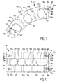
- FIG. 2 shows, in the folded state, a safety support 4 of the segmented ring type according to a first embodiment of the invention.
- the ring 6 of the safety support 4 has several arcuate segments, for example six segments 6a to 6f as shown in FIG. FIG. 2. All segments 6a to 6f can be identical as shown in Figure 2 and in this case they have a length corresponding to an arc of 60 °.
- the invention is of course not limited to a support the ring is subdivided into six identical segments.
- the ring may have a larger number of segments or smaller than six, for example two or three segments as in the the case of the safety support described in EP-A-0 798 141, and the segments can have equal lengths or lengths different as is known.
- the ring segments of the support of safety are generally made of a synthetic material plastic or elastomeric material optionally reinforced with fibers, by example polyamide), it is preferable, for reasons of reduction manufacturing cost, that all segments of ring 6 be identical and have the same length, because a single mold can then suffice to make the ring of the safety support. Likewise, it is better that the ring 6 has at least three segments, as this allows the put in a folded state that facilitates the insertion of the safety support in the tire 3 or the removal of the safety support outside said when at least the outer bead 3b of the tire 3 is clear of the outer seat 2nd of the rim 2.
- the segments 6a to 6f of the ring 6 of the safety support have ends 7a, 8a, 7b, 8b, ... 7f, 8f, respectively, which, in use, are mutually opposite each other, as for example the ends 8c and 7d.
- the mutually opposite ends of the segments 6a to 6f are connected to each other by connecting means 9. preferably, all the connecting means 9 are identical and one of them will be described in detail later.
- segment 6a made by example nylon 6/6 (registered trademark), has two side parts 11a and 12a, respectively inner and outer, which extend parallel to each other and which are bridged by two partitions 13a and 14a and, near the ends 7a and 8a, by bars 15a and 16a.
- the partitions 13a and 14a have a dimension radial corresponding to that of the side portions 11a and 12a of the segment 6a, while the two bars 15a and 16a have a radial dimension smaller than that of segment 6a and are in the immediate vicinity of the outer peripheral surface 17a of the segment 6a, that is to say the surface of said segment which is farthest from the rim 2. It is thus formed three cells 18a, 19a and 21a ( Figure 4) between the two parts 11a and 12a of the segment 6a. Each of the two cells 18a and 21a end opens, in the form of slots, both in the corresponding end face 7a or 8a of the segment 6a and in the inner peripheral surface 22a of said segment 6a, i.e. in its base surface intended to come into contact with the rim 2.
- lights 23a, 24a and 25a are formed in pairs vis-à-vis in the parts 11a and 12a of the segment 6a.
- the cells 18a, 19a and 21a and the lights 23a, 24a and 25a allow both to save money material and, in use, provide ventilation for the corresponding segment 6a when, in case of puncture, the wheel 1 rolls on the floor via the safety support 4.
- Each connecting means 9 comprises at least one element male 26 and at least one female portion 27 (not shown in FIG. but visible in FIGS. 3, 4 and 11 to 17), as well as a mechanism for lever 28 having at least two rods 29 and 31 of lengths different.
- each of the segments 6a to 6f of the ring 6 of the safety support 4 preferably comprises two male elements 26 which are fixed on one of its end faces, for example the face 8a as shown in Figures 3 and 4 for segment 6a, and two parts females 27 which are formed in the other end face of the segment, for example the face 7a as shown in Figures 3 and 4.
- Each female part is able to receive a corresponding male element 26 carried by the adjacent end face of another segment of the ring 6, by example the end face 8f of the segment 6f as shown in the Figures 15 to 17.
- Each male element 26 can be constituted for example by a steel dowel having a threaded portion 26a which is screwed in a tapped hole 32a in the end face 8a of the segment 6a, and a smooth cylindrical portion 26b, with a conical or frustoconical end, which can be slidably engaged in one of the two parts females 27 of the next segment, for example segment 6b following the segment 6a.
- Each female portion 27 may be constituted by a hole blind, cylindrical and smooth, which is formed in the end face 7a of the segment 6a during the molding thereof.
- each blind hole 27 may be provided a countersink 33 adapted to receive a collar 34 carried by the corresponding male element 26 at the junction between its threaded portion 26a and its smooth portion 26b.
- each female part 27 could be constituted by a metal insert in the form of a socket, embedded or embedded in the end face 7a of the segment 6a.
- each segment 6a to 6f is not limited to two, but may be smaller or greater than two depending on the value of the segment width, ie according to the width of the safety support 4, measured in one direction parallel to the axis of rotation of the wheel 1.
- Each lever mechanism 28 preferably comprises two rods 29 and 31, for example molded of a plastic material such nylon 6/6, which are shown in detail in Figures 5 to 9.
- the link 29 has, seen from the side, substantially the shape of a bicycle chain link, with two holes cylindrical 35 and 36 respectively for hinge pins 37 and 38 ( Figures 15-17).
- the rod 29 has a general T-shape as shown in Figure 6, with a wide portion 29a around the hole 35 and a portion narrow 29b in the remaining part of the rod 29.
- link 31 has a shape generally U-shaped, with a base portion 31a and two branches 31b and 31c.
- the two branches 31b and 31c are bridged by a bar 31 d which is in one piece with the two branches.
- a hole cylindrical 39 is formed in the base portion 31a of the rod 31 for a hinge pin 41 (FIGS. 15 to 17) and two holes mutually aligned 42 are formed near the free ends of the branches 31b and 31c to receive the hinge axis 38 mentioned above which is common to two links 29 and 31.
- the wide part 29a of the rod 29 and the rod 31 have the same width and the value of this width corresponds to that of the width of the slot formed between the two lateral parts 11a and 12a of the segment 6a as shown in Figure 18, or the width of the slot formed between the side portions 11f and 12f of the segment 6f, with respect to relates to the part of the rod 31 which lies between these two last side parts in the case of the two connecting rods 29 and 31 connecting the segments 6a and 6f.
- each lever mechanism 28 are articulated to each other by the hinge axis 38 which is threaded into the aligned cylindrical holes 36 and 42 of the rods 29 and 31;
- the rod 29 is articulated to a end of one of the segments, for example segment 6a, by means of the hinge axis 37 whose ends are housed in holes cylindrical aligned cylinders 43 formed in the side portions 11a and 12a of the segment 6a near the end 7a thereof;
- the rod 31 is articulated at the end of another segment, for example segment 6f, at means of the axis 41 whose ends are housed in aligned holes 44 formed in the side portions 11f and 12f of the segment 6f, near the 8f end of it.
- the branches 31b and 31c of the rod 31 are bent so as not to interfere with the part wide 29a of the rod 29 when the rods are in the position shown in FIGS. 14 and 17.
- the branch 31b of the link 31 has a bevelled outer surface in the area of joint joint to the two rods 29 and 31 which is defined by the holes 36 and 42 and the hinge pin 38.
- the surface beveled 31e can be formed by a flat, but it preferably a conical shape.
- the tapered surface 31 e is formed on the branch 31b of the rod 31 in a region facing the flank inside 2di of the 2d throat of the rim 2 during the operations of mounting the safety support 4 on said rim, as shown in the figure 18.
- the surface bevel 31e of each rod 31 comes into contact with the flank inside 2di of the groove 2d and the articulation common to the two links 29 and 31 of each lever mechanism 28 is then subjected to a force having a component directed radially outwards which tends to moving said common hinge radially outwards by compared to the center C of the ring 6.
- each lever mechanism 28 moves from the state shown on the FIG. 16 in the state shown in FIG. 17, thus causing a bringing the ends of the segments of the ring 6 together shown in Fig. 17 and hence a reduction in the inside diameter 6.
- the ring 6 tightens around the rim 2 and the base surfaces 22a to 22f of the segments 6a to 6f are applied against said cylindrical portion or substantially cylindrical 2c of the rim.
- the safety support 4 may further comprise at least one holding element 45 (FIG. 10), preferably six elements of maintaining in the case where the ring 6 has six segments 6a to 6f.
- the retainers 45 serve to temporarily maintain the segments 6a to 6f of ring 6 in a partial approximation state in which the male elements 26 of each segment are partially engaged in the female portions 27 of the corresponding adjacent segment, as we will see later.
- each holding element 45 may be constituted by a clip made of a spring material, for example spring steel wire.
- the clip 45 is shaped to present a generally U-shaped, with a base portion 45a and two branches 45b and 45c which successively, starting from the base portion 45a, mutually parallel parts 45b1 and 45c1 followed by parts mutually convergent 45b2 and 45c2, which are finally followed by mutually diverging end portions 45b3 and 45c3.
- the parts 45b1 and 45c1 of the two branches 45b and 45c have a length corresponding approximately to the width of the arcuate side of each segment of the ring 6 (for example the arcuate lateral part 12a of segment 6a).
- the length of the base portion 45a of the clip 45 is chosen in such a way that when the two branches 45b and 45c of the clip are engaged, for example, respectively in the light 23a of the segment 6a and in the light 25f of the segment 6f, as shown in FIG. FIG. 16, the two branches 45b and 45c maintain a predefined set between the end faces 7a and 8f of the segments 6a and 6f.
- the game predefined value has a value smaller than the length of the smooth portion 26b male elements 26 that protrude on the face 8f end of the segment 6f.
- the predefined set may have a value of 12 mm.
- the two heel locking elements 5 represented in the Figure 1 may have the same width or substantially the same width in the case where the safety support 4 must be placed on the rim 2 in a position centered or approximately centered with respect to the plane median PM of Wheel 1, as shown in Figure 1.
- the two heel blocking elements 5 may have widths noticeably different in the case where the ring 6 of the safety support 4 must be installed on the rim 2 in a position clearly off center by relative to the median plane PM, as for example in the position shown in Figure 20.
- the heel blocking elements 5 may have the shape of a semi-rigid tubular structure ring, which is provided with a valve 46 for inflating the tubular structure ring in the presence of a compressed gas in the tire 3 of the wheel 1, and preventing the deflation of said tubular structure ring when there is a rapid drop in pressure in the tire 3.
- the valve 46 is tared to open for example when the pressure difference between the pressure on the outside of the tubular structure of the heel blocking element 5, therefore the pressure inside the tire 3, and the pressure inside said tubular structure of the element 5 exceeds 0.1 bar (10 4 Pa).
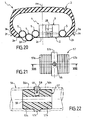
- Each ring-shaped heel blocking element 5 can have a rectangular meridian section with rounded corners, as shown in Figures 1 and 19.
- the structure tubular of the heel blocking element 5 has walls having a multilayer structure, as shown in Figure 19.
- the multilayer structure may comprise successively, from the inside to the outside of the tubular structure, an inner layer of sealing rubber 47 with a high modulus of elasticity, surrounded by a tablecloth 48 armed with oriented threads obliquely, for example at + 27 ° with respect to the median plane PM 'of the meridian section of the tubular structure, and a tablecloth 49 armed with yarns oriented obliquely and crosswise with respect to the threads of the ply 48, for example at an angle of -27 ° relative to the median plane PM '.
- the structure multilayer On its outer peripheral wall which carries the valve 46, the structure multilayer further comprises a web 51 armed with son oriented 90 ° relative to the median plane PM ', which is itself fretted by a tablecloth 52 army of metal wires oriented at 0 ° to the median plane PM '. Finally, the multilayer structure is covered with a tablecloth outer protective rubber 53.
- the outer hoop 52 is intended to reduce the effects of centrifugal force on the wall outer periphery of the tubular structure of the locking element of heel 5 and it is also intended to prevent or limit the deformation of said outer peripheral wall radially towards outside under the effect of the pressure of the gas (air) inside the heel blocking element 5 when the pressure inside the pneumatic 3 has fallen sharply, for example because of a puncture.
- the outer hooping sheet 52 whose reinforcing wires are inextensible, has a larger diameter than that of rim 2f of the rim 2, so that the heel blocking element 5 can be put in place on said rim.
- the multilayer structure described above allows the heel blocking element 5 to deform radially inward under the effect of internal pressure in order to fill at least partially in the groove 2d of the rim 2, while also accepting an increase in the transversal dimension of the heel blocking element 5, that is to say of its measured dimension parallel to the axis of rotation of the wheel 1, in order to block the corresponding heel 3a or 3b of the tire 3 against the rim corresponding 2e or 2f of the rim 2.
- the rim 2 of the wheel is fixed, if it had not already been made, at the rim holder of a conventional apparatus of assembly / disassembly of pneumatic.
- the tire 3 is placed axially in front of the rim 2 so that the inner bead 3a of the tire is located substantially in front of the outer rim 2f of the rim 2.
- the inner bead 3a of the tire is engaged over the outer edge 2f of the rim 2 and it is placed on the part 2c of said rim in an intermediate position corresponding substantially median plane PM.
- the element 5 for blocking the inner bead 3a is introduced inside the cavity of the tire 3 by passing it between the outer rim 2f of the rim 2 and the outer bead 3b of the tire 3, then passing it between the rim 2 and the ring 6 to then slide it on part 2c of the rim 2 until said element 5 comes into contact with the inner bead 3a of the 3. Then, the ring 6 is placed in an axial position, relative to the rim 2, such as the rods 29 and 31 of all the lever mechanisms 28 are located opposite the throat 2d of said rim 2.
- the segments 6a to 6f of the ring 6 are brought closer together manually two by two successively and progressively in beginning for example by the two segments that are in the lower part of the wheel, for example the segments 6d and 6c of FIG. 12, and, after approximation of these segments, by rotating the ring 6 approximately 60 ° to be able to reconcile two other segments, for example segments 6e and 6d.
- Manual operations mutual approximation of the segments 6a to 6f are continued until that all the male elements 26 of the segments are partially engaged in female parts 27 of adjacent segments correspondents.
- spade (partially shown in Figure 18), which is part of the usual tooling of the apparatus of tire assembly / disassembly and which can be moved at a time radially and axially with respect to the rim holder of said apparatus, is brought into contact with the outer face 4b of the safety support 4.
- the dimension of the spade 55, measured in a direction corresponding to the circumferential direction of the ring 6 is larger than the predefined set mentioned above between the segments of the ring 6.
- the rim holder of the assembly / dismounting device of pneumatic is rotated to rotate the rim 2 around the axis of rotation of the wheel, then either the rim holder is moved axially towards the spade 55, or the latter is displaced axially towards the rim holder so as to axially push the ring 6 and therefore also the heel blocking element 5 and the inner bead 3a to the inner rim 2a of the rim 2.
- the surface beveled 31 e of the links 31 lever mechanisms 28 enters into contact with the inner side 2di of the throat 2d of the rim 2.
- the spade 55 of the face is slightly axially 4b exterior of the safety support 4, to spread the outside heel 3b of the tire of the outer rim 2f of the rim 2 just leaving the place to introduce the second heel blocking element 5.
- This second heel blocking element 5 is then introduced gradually to the hand in the cavity of the tire 3 by passing it between the rim 2f exterior of the rim 2 and the outer bead 3b of the tire 3, all by rotating the rim 2 with the help of the rotating rim holder tire mounting / dismounting device.
- the spade 55 is removed, then the outer bead 3b of the tire is put in place. classic way on the 2nd outer seat of the rim 2 by doing it passes over the rim 2f of said rim using appropriate tools of the tire mounting / dismounting device.
- the mounting operations of the support 4, heel blocking elements 5 and tire 3 on the rim 2 requires less than fifteen minutes (not counting the possible balancing and inflating operations) ie a considerably less time than is necessary for the mounting of a conventional safety device of the segmented ring type.
- the dismantling operations of the safety support 4 are carried out as follows. First, the outer heel 3b tire 3 is released from the outside seat 2e of the rim 2 of classic way using appropriate tools from a mounting / dismounting device of tire.
- a conical roller forming part of the usual tools of the tire mounting / dismounting device is placed in contact with the sidewall of the tire 3 which is on the inside of the wheel 1 (the right side in Figure 1). Then the rim holder of the tire assembly / disassembly is rotated and moved axially with respect to the aforementioned roller and / or said roller is moved axially with respect to the rim holder, so as to slide the heel inside 3a of the tire 3, the inner bead blocking element 5, the ring 6 of the safety support and the heel blocking element outside 5 axially outward. Then, as soon as the element of external bead blocking 5 passes over the outer rim 2f of the rim 2, it is extracted manually.
- rods 29 and 31 are free to pivot around their axes 37 and 41 so that their joint joint (axis 38) penetrates into the groove 2d of the rim 2, thus allowing the segments 6a to 6f to deviate from each other. Then, the rotation of the rim holder tire mounting / dismounting device is stopped and, if necessary, the male elements 26 of the segments of the ring 6 are completely out of the corresponding female parts 27 into introducing a suitable tool, for example a screwdriver, between mutually opposite said segments and using the screwdriver as a lever to separate them from each other. In these conditions, the ring 6 can be put in a state such as that shown in FIG.
- a suitable tool for example a screwdriver
- Figure 20 shows another embodiment of the invention in which the safety support 4 is off-center with respect to median plane PM of wheel 1 and deported to the inner side of this last.
- Figure 20 also shows another embodiment heel blocking elements 5. It is here provided four elements of heel lock 5 which each have the shape of a section torus circular meridian.
- each bead blocking element 5 may be example consisting of a piece of pipe 56 made of an elastomeric material armed, whose two ends 56a and 56b are connected to each other by a tubular connector 57 (FIGS. 21 and 22).
- the connector 57 has two male tips 57a and 57b which are respectively nested in the corresponding ends 56a and 56b of the pipe 56 and which have an outer surface whose longitudinal profile has a shape similar to saw teeth.
- the teeth are shaped and oriented way to promote the fitting of each end 57a or 57b in the corresponding end 56a or 56b of the pipe 56 and to prevent or any at least slow down the extraction of each tip out of the end corresponding pipe.
- the two ends 56a and 56b of the pipe 56 can be fixed respectively to the tips 57a and 57b for example by gluing and / or hooping. Between the two end pieces 57a and 57b, the fitting 57 has a collar 57c. A hole 58 extends radially in the neck 57c and opens into the inner channel 59 of the connector 57. A valve 46, similar to the valve described above, is fixed in the hole 58 to allow the filling of the internal cavity of the pipe 56 with compressed air.
- Figure 23 shows another embodiment of the support 4 of the invention, which is usable in the case of a rim having a width smaller than that shown in FIGS. 20 and which is more particularly intended for a wheel for a vehicle lightweight.
- the rim 2 comprises, between the outer side 2 of the 2d throat and the 2nd outer seat, a 2g anti-decoupling boss, still called “hump" by the men of art, to maintain the heel outside 3b of the tire 3 on the outer seat 2e and in contact with the outer rim 2f of the rim 2.
- cylindrical or substantially cylindrical portion 2c of the rim 2 comprises, close to the inner side 2di of the groove 2d, a clipping groove 2h, shallow, which has for example a section semicircular transverse.
- Each segment of the ring 6 of the support of security 4 has, on its base surface 22, a clipping projection 61 which is engaged in the clipping groove 2h when the ring 6 of the safety support 4 occupies a desired axial position with respect to the rim 2, in order to maintain said ring 6 in said axial position desired.
- each segment of the ring 6 is supported by its inner side against the inner heel 3a of 3, in order to maintain said heel 3a on the seat 2b of the rim 2 and against the inner rim 2a of said rim.
- the part of base 62 of each segment of the ring 6 may comprise, on the inside the wheel 1, a beveled inner side surface 63.
- the clipping projection 61 can be made under the shape of a rib extending continuously in the direction circumferential ring 6 over all or part of the length of each segment 6a to 6f of said ring 6.
- said clipping protrusion can be realized in the form of a series of bosses, for example in shaped spherical caps, spaced in the circumferential direction of the ring 6.
- the clipping projection 61 that is to say the rib or series of bosses, can be worn by the surface substantially cylindrical 2c of the rim 2, while the groove of clipping 2h can be formed in the base surface 22a, ... 22f of segments 6a, ... 6f of the ring 6 of the safety support.
- each segment of the ring 6 of the safety support 4 has a width such that it extends into the axial direction of the wheel 1 substantially until the transition between the outer side 2de of the throat 2d and the boss anti-decoupling 2g and thus completely or almost completely covers the throat 2d.
- the base portion 62 of each segment of the ring 6 of the safety support 4 is strongly beveled as shown at 64 in Figure 23.
- the ring 6 of the safety support 4 shown on the Figure 23 can be made in a manner similar to that described above. about the embodiment of Figures 1 to 18 (except for heel blocking elements 5 which, in this case, are absent).
- the segments of the ring 6 are assembled to each other by male elements 26 and female parts 27 and by lever mechanisms 28 quite similar to those described upper.
- each lever mechanism 28 had two links 29 and 31.
- the invention should not be limited to with two links, because to reach the goal which is at the base of the present invention, it is equally possible to use a mechanism comprising for example three links, like the mechanism 28 represented in FIG. 24 which partially corresponds to FIG. first embodiment.
- the mechanism 28 comprises two rods 29 and 29 'identical and of the same length, which are hinged respectively by the axes 37 and 41 each at a respective end two segments of the ring of the safety support, for example the segments 6a and 6f, and a third link 65, longer than the two rods 29 and 29 'and hinged thereto respectively by the pins 38 and 38 '.
- the link 65 globally an H-shape, with two parallel branches 65a, of which only one is visible in Figure 24 and which are bridged by one or two sleepers 65b.
- the rod 65 has a sectional view along the line A-A and according to line B-B of FIG. 24, a shape similar to that shown in Figure 9, that is, one of the parallel branches 65a of the link 65 has, at both ends, a bevelled surface similar to the bevelled surface 31e shown in Figure 9, in order to facilitate the sliding of the ends of the rod 65 along the side inside 2di of the rim 2 when setting up the safety support 4 on part 2c of said rim.
- the link 29 (as also the rod 29 ') can have in the region of the joint defined by the axis 38 (or by the axis 38 'for the rod 29') a curved outer surface 29c which has a spiral profile or which is offset from the axis 38.
- the tightening of the segments of the ring 6 of the safety support 4 can be amplified by a cam effect given by the surface 29c of the rod 29 in contact with the rim when the rod 29 pivots about the axis 37.
Landscapes
- Engineering & Computer Science (AREA)
- Mechanical Engineering (AREA)
- Tires In General (AREA)
Applications Claiming Priority (2)
| Application Number | Priority Date | Filing Date | Title |
|---|---|---|---|
| FR0404208 | 2004-04-21 | ||
| FR0404208A FR2869262B1 (fr) | 2004-04-21 | 2004-04-21 | Appui de securite pour roue de vehicule |
Publications (1)
| Publication Number | Publication Date |
|---|---|
| EP1588870A1 true EP1588870A1 (de) | 2005-10-26 |
Family
ID=34942062
Family Applications (1)
| Application Number | Title | Priority Date | Filing Date |
|---|---|---|---|
| EP05290733A Withdrawn EP1588870A1 (de) | 2004-04-21 | 2005-04-04 | Notlaufring für Fahrzeugrad |
Country Status (3)
| Country | Link |
|---|---|
| US (1) | US7264031B2 (de) |
| EP (1) | EP1588870A1 (de) |
| FR (1) | FR2869262B1 (de) |
Cited By (6)
| Publication number | Priority date | Publication date | Assignee | Title |
|---|---|---|---|---|
| FR2951994A1 (fr) * | 2009-11-04 | 2011-05-06 | Hutchinson | Dispositif de roulage a plat pour vehicule automobile et ensemble monte l'incorporant |
| GB2472373B (en) * | 2009-05-07 | 2013-11-06 | Run Flat Systems Ltd | A runflat device and a method for fitting the same |
| RU2540037C2 (ru) * | 2013-05-23 | 2015-01-27 | Федеральное государственное казенное учреждение "3 Центральный научно-исследовательский институт" Минобороны России | Безопасное колесо транспортного средства |
| RU2653913C2 (ru) * | 2016-07-04 | 2018-05-15 | Федеральное государственное казенное военное образовательное учреждение высшего образования "Рязанское высшее воздушно-десантное ордена Суворова дважды Краснознаменное командное училище имени генерала армии В.Ф. Маргелова Министерства обороны Российской Федерации | Безопасное колесо транспортного средства |
| US20180186196A1 (en) * | 2013-02-20 | 2018-07-05 | Run Flat Systems Limited | Runflat device and fitting method |
| RU2750478C1 (ru) * | 2020-11-20 | 2021-06-28 | Шаньдун Хонгуанг Руббер Технолоджи Со., Лтд. | Устройство защиты от аварии из-за прокола шины автомобиля |
Families Citing this family (7)
| Publication number | Priority date | Publication date | Assignee | Title |
|---|---|---|---|---|
| EP2139704A4 (de) * | 2007-03-22 | 2010-09-29 | Khaled Khatib | Runflat-reifensystem und -vorrichtung |
| US8281835B2 (en) * | 2008-03-24 | 2012-10-09 | Dynamic Runflats, Inc. | Run-flat support assembly for a pneumatic tired wheel and method for use of same |
| US8196629B2 (en) * | 2008-05-01 | 2012-06-12 | Dynamic Runflats, Inc. | Run-flat support system for a pneumatic tired wheel and method for installing same |
| WO2010011340A2 (en) * | 2008-07-24 | 2010-01-28 | Hutchinson S.A. | Runflat system with interconnected sectors |
| US20110297287A1 (en) * | 2010-06-04 | 2011-12-08 | Vianna Alexandre S | Applied to band for protection of vehicular wheels and tires |
| WO2014055078A1 (en) * | 2012-10-01 | 2014-04-10 | Scennco, Inc. | Segmented tire apparatus |
| CN108891207B (zh) * | 2018-08-02 | 2023-09-08 | 湖北源久汽车零部件有限公司 | 一种汽车防爆胎安全机构 |
Citations (7)
| Publication number | Priority date | Publication date | Assignee | Title |
|---|---|---|---|---|
| US2286507A (en) * | 1941-04-26 | 1942-06-16 | Quinn Hubert | Noncollapsible pneumatic tire |
| US3420288A (en) * | 1966-04-08 | 1969-01-07 | Ernest A Unruh | Internal safety wheel for pneumatic tires |
| US3828836A (en) * | 1972-12-13 | 1974-08-13 | C Bradley | Safety wheel and tire securing assembly |
| US4046182A (en) * | 1974-08-08 | 1977-09-06 | Dunlop Limited | Safety tire and wheel assemblies |
| DE2842929A1 (de) * | 1978-10-02 | 1980-04-17 | Joachim Schindler | Antiausbrechvorrichtung fuer kraftfahrzeuge |
| EP0798141A1 (de) * | 1996-03-26 | 1997-10-01 | Hutchinson | Notlaufvorrichtung für Fahrzeug und Verfahren zu ihrer Montage |
| JP2002178727A (ja) * | 2000-12-08 | 2002-06-26 | Bridgestone Corp | タイヤ用中子体、中子付きリムホイール及びタイヤ・リム組立体 |
Family Cites Families (6)
| Publication number | Priority date | Publication date | Assignee | Title |
|---|---|---|---|---|
| FR2416785A1 (fr) * | 1978-02-13 | 1979-09-07 | Rhone Poulenc Ind | Procede d'impermeabilisation aux gaz de corps creux en polyester |
| FR2754215B1 (fr) | 1996-10-07 | 1998-12-04 | Hutchinson | Dispositif de roulage a plat pour vehicule automobile |
| FR2808734B1 (fr) * | 2000-05-11 | 2003-02-07 | Hutchinson | Dispositif de roulage a plat pour vehicule automobile |
| DE60321802D1 (de) * | 2002-05-28 | 2008-08-07 | Topy Ind | Notlauf-stützring |
| US7575030B2 (en) * | 2003-12-10 | 2009-08-18 | Hutchinson | Runflat device for a motor vehicle, and a mounted assembly incorporating it |
| JP4410575B2 (ja) * | 2004-02-02 | 2010-02-03 | 住友ゴム工業株式会社 | サポートリング及びそれを用いたタイヤ組立体 |
-
2004
- 2004-04-21 FR FR0404208A patent/FR2869262B1/fr not_active Expired - Fee Related
-
2005
- 2005-04-04 EP EP05290733A patent/EP1588870A1/de not_active Withdrawn
- 2005-04-18 US US11/108,529 patent/US7264031B2/en not_active Expired - Fee Related
Patent Citations (7)
| Publication number | Priority date | Publication date | Assignee | Title |
|---|---|---|---|---|
| US2286507A (en) * | 1941-04-26 | 1942-06-16 | Quinn Hubert | Noncollapsible pneumatic tire |
| US3420288A (en) * | 1966-04-08 | 1969-01-07 | Ernest A Unruh | Internal safety wheel for pneumatic tires |
| US3828836A (en) * | 1972-12-13 | 1974-08-13 | C Bradley | Safety wheel and tire securing assembly |
| US4046182A (en) * | 1974-08-08 | 1977-09-06 | Dunlop Limited | Safety tire and wheel assemblies |
| DE2842929A1 (de) * | 1978-10-02 | 1980-04-17 | Joachim Schindler | Antiausbrechvorrichtung fuer kraftfahrzeuge |
| EP0798141A1 (de) * | 1996-03-26 | 1997-10-01 | Hutchinson | Notlaufvorrichtung für Fahrzeug und Verfahren zu ihrer Montage |
| JP2002178727A (ja) * | 2000-12-08 | 2002-06-26 | Bridgestone Corp | タイヤ用中子体、中子付きリムホイール及びタイヤ・リム組立体 |
Non-Patent Citations (1)
| Title |
|---|
| PATENT ABSTRACTS OF JAPAN vol. 2002, no. 10 10 October 2002 (2002-10-10) * |
Cited By (8)
| Publication number | Priority date | Publication date | Assignee | Title |
|---|---|---|---|---|
| GB2472373B (en) * | 2009-05-07 | 2013-11-06 | Run Flat Systems Ltd | A runflat device and a method for fitting the same |
| FR2951994A1 (fr) * | 2009-11-04 | 2011-05-06 | Hutchinson | Dispositif de roulage a plat pour vehicule automobile et ensemble monte l'incorporant |
| EP2322361A1 (de) | 2009-11-04 | 2011-05-18 | Hutchinson | Notlaufvorrichtung für Kraftfahrzeug und damit montierte Anordnung |
| US8978726B2 (en) | 2009-11-04 | 2015-03-17 | Hutchinson | Flat-running device for motor vehicle and mounted assembly incorporating same |
| US20180186196A1 (en) * | 2013-02-20 | 2018-07-05 | Run Flat Systems Limited | Runflat device and fitting method |
| RU2540037C2 (ru) * | 2013-05-23 | 2015-01-27 | Федеральное государственное казенное учреждение "3 Центральный научно-исследовательский институт" Минобороны России | Безопасное колесо транспортного средства |
| RU2653913C2 (ru) * | 2016-07-04 | 2018-05-15 | Федеральное государственное казенное военное образовательное учреждение высшего образования "Рязанское высшее воздушно-десантное ордена Суворова дважды Краснознаменное командное училище имени генерала армии В.Ф. Маргелова Министерства обороны Российской Федерации | Безопасное колесо транспортного средства |
| RU2750478C1 (ru) * | 2020-11-20 | 2021-06-28 | Шаньдун Хонгуанг Руббер Технолоджи Со., Лтд. | Устройство защиты от аварии из-за прокола шины автомобиля |
Also Published As
| Publication number | Publication date |
|---|---|
| US7264031B2 (en) | 2007-09-04 |
| FR2869262B1 (fr) | 2007-09-14 |
| US20050236082A1 (en) | 2005-10-27 |
| FR2869262A1 (fr) | 2005-10-28 |
Similar Documents
| Publication | Publication Date | Title |
|---|---|---|
| EP1588870A1 (de) | Notlaufring für Fahrzeugrad | |
| WO2009092917A2 (fr) | Dispositif de raccordement rapide d'un tube avec bague de securite | |
| EP0878328B1 (de) | Halbhohlreifen und Walze mit solchen Reifen | |
| EP1807648B1 (de) | Segmentierter klemmring und entsprechende anordnung und befestigungsverfahren | |
| EP0351362B1 (de) | Spurkranz für eine Antirutschvorrichtung | |
| WO2010004233A1 (fr) | Dispositif de serrage comprenant un collier | |
| CA2603272C (fr) | Anneau de verrouillage dans un ensemble de montage d'un pneumatique sur un moyeu de vehicule | |
| EP0956212B1 (de) | Notlaufvorrichtung für auto und verfahren zu seiner montage | |
| WO2012107678A1 (fr) | Vis destinee a l'extrusion ou au melangeage d ' elastomeres et son procédé d'assemblage | |
| WO2011030269A1 (fr) | Dispositif de roulage a plat pour vehicule automobile, ensemble monte l'incorporant et son procede de montage/ demontage. | |
| EP1254034B1 (de) | Reifenwulst mit verlängerter mobilität | |
| CA2163581A1 (fr) | Tambour d'assemblage de pneumatique | |
| EP0159274A2 (de) | Vorrichtung zum Festspannen eines Luftreifens auf einer Felge | |
| EP1289779A1 (de) | Reifen mit einem verstärkungselement in mindestens einer seitenwand und montierte reifen/felge einheit | |
| EP1853439B1 (de) | Fahrzeugantiblockiersystem | |
| WO2002051651A1 (fr) | Ensemble consitute d'un pneumatique et d'une piece d'etancheite et procede de fabrication | |
| EP3112242A1 (de) | Fixierstift und nabe für rad eines fahrrads | |
| WO2004041685A2 (fr) | Maillon pour tapis de convoyage d'objets quelconques | |
| EP1838540B1 (de) | Reifen, von dem mindestens ein wulstsitz eine rippe umfasst | |
| FR2809348A1 (fr) | Pneumatique comprenant un profile de renfort dans au moins un flanc et ensemble pneumatique/jante comprenant un tel pneumatique | |
| EP0133072A2 (de) | Rad für ein Fahrrad mit einem Schlauchreifen | |
| WO2008129169A1 (fr) | Pneumatique pour cycle et jante adaptée à ce pneumatique, ainsi qu'une roue de cycle les comportant | |
| FR2843335A1 (fr) | Dispositif de securite pour les pneumatiques montes sur des jantes monobloc a gorge de montage. | |
| FR2809054A1 (fr) | Pneumatique, ensemble pneumatique et jante | |
| EP1612063A1 (de) | Vorrichtung zum Demontieren eines Reifens von einer Felge mit nach aussen geneigten Schultern |
Legal Events
| Date | Code | Title | Description |
|---|---|---|---|
| PUAI | Public reference made under article 153(3) epc to a published international application that has entered the european phase |
Free format text: ORIGINAL CODE: 0009012 |
|
| 17P | Request for examination filed |
Effective date: 20050728 |
|
| AK | Designated contracting states |
Kind code of ref document: A1 Designated state(s): AT BE BG CH CY CZ DE DK EE ES FI FR GB GR HU IE IS IT LI LT LU MC NL PL PT RO SE SI SK TR |
|
| AX | Request for extension of the european patent |
Extension state: AL BA HR LV MK YU |
|
| AKX | Designation fees paid |
Designated state(s): DE FR GB IT |
|
| 17Q | First examination report despatched |
Effective date: 20120120 |
|
| RAP1 | Party data changed (applicant data changed or rights of an application transferred) |
Owner name: MICHELIN RECHERCHE ET TECHNIQUE S.A. Owner name: COMPAGNIE GENERALE DES ETABLISSEMENTS MICHELIN |
|
| STAA | Information on the status of an ep patent application or granted ep patent |
Free format text: STATUS: THE APPLICATION IS DEEMED TO BE WITHDRAWN |
|
| 18D | Application deemed to be withdrawn |
Effective date: 20130906 |