EP1588813A1 - Stitching device with feeding apparatus for at least one continuous wire - Google Patents
Stitching device with feeding apparatus for at least one continuous wire Download PDFInfo
- Publication number
- EP1588813A1 EP1588813A1 EP05103016A EP05103016A EP1588813A1 EP 1588813 A1 EP1588813 A1 EP 1588813A1 EP 05103016 A EP05103016 A EP 05103016A EP 05103016 A EP05103016 A EP 05103016A EP 1588813 A1 EP1588813 A1 EP 1588813A1
- Authority
- EP
- European Patent Office
- Prior art keywords
- wire
- stitching
- stapling
- mode
- stapling apparatus
- Prior art date
- Legal status (The legal status is an assumption and is not a legal conclusion. Google has not performed a legal analysis and makes no representation as to the accuracy of the status listed.)
- Granted
Links
Images

Classifications
-
- B—PERFORMING OPERATIONS; TRANSPORTING
- B42—BOOKBINDING; ALBUMS; FILES; SPECIAL PRINTED MATTER
- B42B—PERMANENTLY ATTACHING TOGETHER SHEETS, QUIRES OR SIGNATURES OR PERMANENTLY ATTACHING OBJECTS THERETO
- B42B4/00—Permanently attaching together sheets, quires or signatures by discontinuous stitching with filamentary material, e.g. wire
Definitions
- the invention relates to staplers with a feeding device for feeding at least an endless stitching wire according to the preamble of claim 1 or 3.
- DD 100 437 shows a feeding device for feeding at least one endless one Stapling wire from a stapling wire stock moved into one when feeding as a whole Stapler with a first conveyor for continuously conveying the Stapling wire from the stitching wire supply and with a second conveyor for Conveying the stitching wire.
- BE 554 705 A discloses a feeder with an intermediate storage formed loops of the supplied material.
- DE-PS 123 706 describes a stapler in which the switching of Double production takes place on collective production by changing the stitching wire feed.
- the invention is based on the object staplers with a feeder for Supplying at least one endless stitching wire with improved wire feed create.
- the achievable with the present invention consist in particular that the Switching the stapler from the first to the second mode Reconfigure the separator or the second stapling head no longer necessary is.
- the second stapling head remains in the same position as in the second operating mode in the first mode of the stapler.
- the batch feeder is the second stapling head in the second mode, however, not supplied with wire sections, so that the second stapling head perform a stapling movement in the second mode like in the first mode, but there is no stitching, because the second stapling head of the necessary wire section is missing.
- staplers can also be the stapler in the first mode the feeding device continuously feed the stitching wire.
- the stitching wire can then move at a fixed speed.
- speed of the stitching wire is subject to change. At times, speeds may be greater than the fixed ones Speed of stitching wire in the first mode.
- a Top speed of the stitching wire in the second mode be twice as large like a fixed speed of the stitching wire in the first mode.
- the stitching wire may become uniform during feeding accelerated or decelerated. This can be during an acceleration phase of the stitching wire or during a deceleration phase of the stitching wire or both occur during acceleration as well as during deceleration of the stitching wire.
- the Delay phase may occur immediately after the acceleration phase be initiated so that the stitching wire immediately upon reaching his Top speed is delayed again, without this top speed for to maintain for a longer time.
- the stapling heads are on one Stapling cylinder arranged.
- the stitching heads of the stapling head pair can be diametrically on Heft cylinder be arranged. It is also possible to have a plurality of in the axial direction staggered pairs of stitching heads on the stitching cylinder provided.
- the separator comprises blades which are paired to Shearing the stitching wire together.
- the blades on the Heftgro pfen be formed.
- it may be at the stapling heads trained blades act around protrusions, with which the stitching heads in Interaction of another blade, which is an edge of an exit z.
- shear in the first mode of the stapler both the first stapling head and the second stapling head detach wire sections from the stapling wire, in order to perform a stapling with these afterwards.
- the second mode shears only the first stapling head a wire section from the stitching wire, while the second Stapling head as a result of the batchwise supply of the stitching wire no wire section can shear because the stitching wire has not yet been fed.
- the stapler is most preferably designed such that it during a Operation between the first and the second mode is switchable. He is suitable therefore particularly well suited for use in a central control room Press.
- the feeding device of the stapler preferably comprises a first and a second conveyor, wherein the first serves, in both modes stitching wire to continuously promote from one main stock to an intermediate stock and the second at least in the second mode, the stitching wire from the intermediate supply intermittently further.
- Such an embodiment is particularly advantageous when it applies, by means of the second clamp the stitching wire from a when feeding as a whole moving stapler main stock, such as a wire reel to remove. Because such a coil of wire may have a considerable mass of up to 100 kg the first conveyor can apply considerable torque; there she keeps the main supply moving evenly due to continuous production Nevertheless, a low acceleration capacity is sufficient, i. H. a low one Drive power of the first conveyor.
- the second conveyor In the second operating mode, it only has to accelerate the content of the intermediate supply. However, its mass corresponds only approximately to that of a staple, so that despite a low drive power and the second conveyor for timely supply the bonding wire required high accelerations can be achieved.
- the stitching wire in the second mode of the second conveyor accelerated and decelerated, while from the first Conveyor continuously fed, it comes to a periodic forming jam of the stitching wire on the second conveyor.
- the second conveyor In order for in the second mode before the second conveyor accumulate periodically Stitching wire to create space for evasion is also particularly preferred Storage space for the stitching wire between the first and the second conveyor intended.
- the second conveyor can operate continuously, so that, like the first conveyor, it continuously advances the stitching wire, or the second conveyor may be turned off the stitching wire in the first mode be. In the latter case, the first conveyor alone provides for the forward movement and the feeding of the stitching wire.
- the second Conveyor during the first mode intermittently, albeit with an im Medium higher conveying speed than in the second mode to operate; Whether this is appropriate depends inter alia on the geometric conditions of the Stapling heads and their movement.
- the feed device comprises a sensor for detecting the position of the respective stapling head to be supplied with wire sections.
- the feeder then preferably further comprises a control unit based in the second mode the detection results of the sensor controls the second conveyor. This will be an automated operation of the stapler possible.
- the conveyors can, for example, a stapling the wire clamping Include roller pair. In general, it can be at the terminals but any other means clamping the stitching wire and advancing means such.
- Fig. 1 is a schematic representation of a stapler in front view to see.
- Fig. 2 shows the stapler of Fig. 1 from a lateral view.
- On a lateral surface a rotatably mounted stitching cylinder 03 is a pair of stitching heads 01; 02, consisting from a first stapling head 01 and a second stapling head 02, arranged.
- the stitching heads 01; 02 are arranged diametrically on the stitching cylinder 03.
- the stitching heads 01; 02 each have two projections 08; 17, z. B. blades 08; 17, which has a recess 18 or limit 19 in the longitudinal direction of the stapling cylinder 03.
- the protrusions 08; 17 each have a directed in the radial direction of the stapling cylinder 03 stage 22. In Fig. 1, this step 22 is located at the projections 17 of the stapling head 02 on the facing away from the viewer and is therefore not visible.
- a feed device 04, 07 essentially comprises one parallel to the longitudinal axis of the Stapling cylinder 03 extending feed tube 04 and a servo motor 07, z. B.
- one Electric motor 07 drives a pair of rollers. At a tack side end forms the Feed tube 04 an edge 21.
- An unrolled from an endless roll, not shown Stapling wire 06 is clamped between the rollers driven by the servo motor 07 and is pushed by them through the feed tube 04.
- a wire section 09 of the Stapling wire 06 protrudes in FIG. 1 from the end of the feed tube 04 that is at the stapler head.
- FIG. 1 shows this wire section 09 in a moment immediately before he Cooperation of the edge 21 of the feed tube 04 and facing this edge Projection 08 or 17 of the stapling head 01 is sheared off from the stitching wire 06.
- a cylinder 23 is used to staple the stapler cooperates, and a bending roller 28 is not shown in Fig. 1; but they are for it but in Fig. 2 located.
- the stapler is employed on the rotatably mounted cylinder 23, the closing plates 26 has.
- a dashed line circumferential circle 27th drawn in, the ends of the stitching heads 01; 02 during a rotation of the stapling cylinder Go through 03.
- This peripheral circle 27 forms with the cylinder 23 a stitching gap, through a staple stack of sheets 24 is guided by sheets.
- a bending roller 28 is at the height of the recesses 18; 19 such between the stapler and the cylinder 23 arranged that it partially penetrates into the circumferential circle 27 and thereby in the Recesses 18; 19 intervenes.
- the stapling cylinder 03 rotates in through an arrow in Fig. 2 indicated direction.
- the stitching wire 06 from the servo motor 07 continuously through the feed tube 04 pushed, so that at the end of the staple head feed tube 04 outstanding wire section 09 of the stitching wire 06 evenly over time gets longer.
- the propulsion speed of the stitching wire 06 and the rotational speed of the stapling cylinder 03 are coordinated so that when the wire section 09 has reached the width of the stapling head 01 or 02 corresponding length I, the step 22nd a stapling head 01 or 02, in FIG. 1 that of the first stapling head 01, the stapling wire 06 presses against the edge 21 and a wire section 09 from the stitching wire 06 shears off.
- the Wire section 09 is taken from the stapling head 01.
- the stapling head 01 leads, in a known manner, to a stitching of the stapling head Stack of sheets 24 out.
- the wire section 09 in the further course of Rotation pressed against the bending roller 28. Because the bending roller 28 is arranged such that when passing through a stapling head 01; 02 in its recess 18; 19 intervenes, the wire portion 09 of the bending roller 28 in the respective recess 18; 19 pressed. Thereby, the wire portion 09 becomes a shape having a straight line Middle section and two legs bent at 90 ° bent.
- the stapling head 01 reaches the cylinder 23, he pushes the then bent wire section 09 with the Tips of the legs ahead through the stack of sheets 24.
- the cylinder 23 has gone up rotated so far that one of the closing plates 26 the stapling head 01 is opposite. With the closing plate 26 of the stapling head 01 acts together and performs the stapling of Stack of sheets 24 with the wire section 09 to the end.
- the stapling cylinder 03 continues to rotate and also the stitching wire 06 is continuously pushed by the servo motor 07 through the feed tube 04, so that upon arrival of the stapling head 02 at the end of the feed tube 04 at the end of the stapling head new wire section 09 of length I protrudes from this, the on the plane described way abuts the projection 08 of the stapling head 02 and of the stage 22 and the edge 21 is sheared off.
- the new wire section 09 is from the second Stapling head 02 taken, whereupon this as the first stapling head 01 to the same described manner performs a stitch with him. Subsequently, the repeated Operation in the manner described.
- the respective not stapling head 01 or 02 umkonkonfigurieren so that with its projections 08 or 17 and the edge 21 no wire section 09 can be sheared off more. moreover a feed speed of the stitching wire 06 must be reduced so that the Wire section 09 when shearing off by the respective stapling stapling head 01 or 02 has the correct length I.
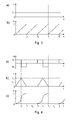
- FIG. 3 a For clarification, in the case of the double production in FIG. 3 a a speed-time diagram and in FIG. 3 b an associated location-time diagram for the tip of the stitching wire 06 are shown. Since the stitching wire 06 is fed with continuous speed v in the double production, the speed v of the stitching wire 06 has the constant value v 1 for all times t. This is shown in the speed-time diagram of FIG. 3a.
- the path traveled by the stitching wire 06 corresponds to the removal of the tip of the stitching wire 06 from the edge 21, this path being at the same time the length of the wire section 09 of the stitching wire 06 protruding at the stapler side end of the feed tube 04.
- this wire section 09 begins to form; its length increases linearly up to time T 1 .
- the end section has reached the length I and is sheared off from the stitching wire 06 by the projection 08 of the stitching head 01 and the edge 21 as the wire section 09 having this length I.
- a renewed projecting wire section 09 whose length in turn increases linearly, is formed at the end of the feed tube 04 at the head end.
- This new wire section 09 is sheared off at the time T 2 from the projection 17 of the second stitching head 02 and the edge 21 also with a length I as the wire section 09.
- FIGS. 4a, 4b and 4c Corresponding diagrams are shown for the advancement of the stitching wire 06 for the second mode of operation, ie in collective production, in FIGS. 4a, 4b and 4c.
- the feed of the stitching wire 06 in the second mode is in batches, wherein in FIGS. 4a, 4b and 4c, a preferred variant of such a batch feed is shown.
- the type of feed can be easily adjusted via the servo motor 07.
- the stitching wire 06 From the time t 1 to the time T 1 , the stitching wire 06 with an acceleration -a 0 with the same amount as a 0 , but with the opposite sign, delayed.
- the associated speed profile of the stitching wire 06 is shown in Fig. 4b.
- the speed v of the stitching wire 06 increases linearly up to a peak value v 2 , in order to linearly fall back to the value 0 from the time t 1 to the time T 1 .
- this projection is sheared from the projection 08 of the stapling head end of the feed tube 04 passing stapling head 01 and the edge 21 and taken as a wire section 09 with a length I.
- the stapling wire 06 remains at rest and undergoes no advance. Both its velocity v and its acceleration a are zero.
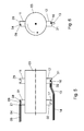
- FIGs. 5 and 6 another embodiment of a stapler once in Front view and once shown in side view.
- this stapler has a second stapling head pair 11, 12, which is on the same Stapling cylinder 03 as the first stapling head pair 01, 02 is arranged, with each diametrical arrangement of the stitching heads 01; 02, 11; 12.
- the stapling head pairs 01, 02 and 11, 12 are arranged staggered in the axial direction of the stapling cylinder 03.
- the stitching heads 11; 12 have protrusions 29; 31, z. B. blades 29; 30 on.
- a first feed tube 04 serves for Supply of stitching heads 01; 02 with wire sections 09, from a first stitching wire 06, as described above, of protrusions 08; 17 of the stitching heads 01; 02 and the edge 21 sheared off.
- a second supply pipe 13 for supplying the Pair of stitching heads 11; 12 provided. It has an edge at the head end 32 on.
- a stitching wire 14 is supplied, of which the Protrusions 29; 31 of the stitching heads 11; 12 with the edge 32 each wire sections 16th shear.
- the feed tube 13 In order to abut a stapling head 01; 02 of the first pair of stitching heads 01; 02 to avoid the second feed tube 13, the feed tube 13 to that in Fig. 5th shown manner and forms between the stitching head pairs 01, 02 and 11, 12 two Bends.
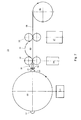
- FIG. 6 A preferred embodiment of the feed device 33 of a stapler is shown in FIG. 6 in schematic form.
- a viewing direction turned by 90 °.
- the feeder 33 includes a first motor 37, z. B. electric motor 37 with a driven by this first conveyor 38, z. B. pair of rollers 38 and a second motor 34, z. B. electric motor 38 with a second driven by this Conveyor 36, z. B. pair of rollers 36, and a wire cutting nozzle 39 with Feed tube 04 and edge 21, and a sensor 41 with control unit.
- the roller pairs 36; 38 are spaced from each other by a storage space 43.
- the one of the wire reel 42 unwound stitching wire 06 only passes through the first pair of rollers 38, passes through the Storage space 43, then passes through the second pair of rollers 36 and finally reaches the feed tube 04 of the wire cutting nozzle 39, from which it exits at the edge 21.
- the stapler If the stapler is operated with the feeder 33 in the first mode, so drives the first motor 37, the first pair of rollers 38, which the stitching wire 06 of the up to 100 kg heavy wire roll 42 unwinds continuously. With the same constant Speed v at which the stitching wire 06 is transported by the pair of rollers 38 is, the stitching wire 06 from the second pair of rollers 36, the weaker second Motor 34 is driven, inserted into the feed tube 04 and exits at the edge 21 the wire cutting nozzle 39 from. As described above, is a well-worn Wire section 09 alternately from one of the stitching heads 01: 02 from the stitching wire 06th separated and taken away.
- the rollers of the second Roller pair 36 in the first mode of stitching wire 06 ab sensible, so that the Stapling wire 06 is driven by the first pair of rollers 38 alone.
- the first motor 34 is the one with the sensor 41st connected control unit always set in motion when the sensor 41 the Passage of the stitching head to be supplied with stitching wire 01 is detected.
- rollers of the second pair 36 are lightweight, with low moment of inertia, designed to a high acceleration by the motor 34 despite low power of the same allow, and the clamping force between the rollers of the pair 36 and the stitching wire 06 is not significantly larger than to accelerate the stitching wire 06 of the wire loop 44 required.
- the second motor 34 therefore requires no precise Speed control; as soon as the stitching wire 06 in the storage space 43 - in good time the passage of the stapling head 01 in front of the edge 21 - pulled tight, he slips between the rolls of the pair 36, so that between the time of getting tightened the stitching wire 06 and the shearing by the stapling head 01, the propulsion speed the stitching wire 06 is determined by the speed v of the first pair of rollers 38.
- control unit switches the second motor 34 back on out, so that after shearing no stitching wire 06 more of the wire cutting 39th exits until the stapling head 02, which is not to be supplied, has passed the edge 21.
Abstract
Description
Die Erfindung betrifft Heftapparate mit einer Zuführeinrichtung zum Zuführen wenigstens eines endlosen Heftdrahtes gemäß dem Oberbegriff des Anspruchs 1 oder 3.The invention relates to staplers with a feeding device for feeding at least an endless stitching wire according to the preamble of claim 1 or 3.
Die DD 100 437 zeigt eine Zuführeinrichtung zum Zuführen wenigstens eines endlosen Heftdrahtes aus einem beim Zuführen als Ganzes bewegten Heftdrahtvorrates zu einem Heftapparat mit einer ersten Fördereinrichtung zum kontinuierlichen Fördern des Heftdrahtes aus dem Heftdrahtvorrat und mit einer zweiten Fördereinrichtung zum Fördern des Heftdrahtes.DD 100 437 shows a feeding device for feeding at least one endless one Stapling wire from a stapling wire stock moved into one when feeding as a whole Stapler with a first conveyor for continuously conveying the Stapling wire from the stitching wire supply and with a second conveyor for Conveying the stitching wire.
Die BE 554 705 A offenbart eine Zuführeinrichtung mit einer als Zwischenvorrat ausgebildeten Schlaufen des zugeführten Materials.BE 554 705 A discloses a feeder with an intermediate storage formed loops of the supplied material.
Die DE-PS 123 706 beschreibt einen Heftapparat bei dem die Umschaltung von Doppelproduktion auf Sammelproduktion durch Veränderung der Heftdrahtzufuhr erfolgt.DE-PS 123 706 describes a stapler in which the switching of Double production takes place on collective production by changing the stitching wire feed.
Der Erfindung liegt die Aufgabe zugrunde, Heftapparate mit einer Zuführeinrichtung zum Zuführen wenigstens eines endlosen Heftdrahtes mit verbesserter Drahtzuführung zu schaffen.The invention is based on the object staplers with a feeder for Supplying at least one endless stitching wire with improved wire feed create.
Die Aufgabe erfindungsgemäß durch die Merkmale des Anspruchs 1 oder 3 gelöst.The object is achieved by the features of claim 1 or 3.
Die mit der Erfindung erzielbaren Vorteile bestehen insbesondere darin, dass zum Umschalten des Heftapparates von der ersten in die zweite Betriebsart ein Umkonfigurieren der Trenneinrichtung oder des zweiten Heftkopfes nicht mehr notwendig ist. Der zweite Heftkopf verbleibt auch in der zweiten Betriebsart in derselben Position wie in der ersten Betriebsart des Heftapparates. In Folge der schubweisen Zuführung wird der zweite Heftkopf in der zweiten Betriebsart dagegen nicht mit Drahtabschnitten versorgt, so dass der zweite Heftkopf in der zweiten Betriebsart zwar eine Heftbewegung ausführen mag wie in der ersten Betriebsart, dabei jedoch keine Heftung zustande kommt, weil dem zweiten Heftkopf der dafür nötige Drahtabschnitt fehlt. Dies erlaubt einerseits eine vereinfachte Konstruktion der Heftköpfe bzw. der Trenneinrichtung, da sie nicht mehr umkonfigurierbar sein müssen.The achievable with the present invention consist in particular that the Switching the stapler from the first to the second mode Reconfigure the separator or the second stapling head no longer necessary is. The second stapling head remains in the same position as in the second operating mode in the first mode of the stapler. As a result of the batch feeder is the second stapling head in the second mode, however, not supplied with wire sections, so that the second stapling head perform a stapling movement in the second mode like in the first mode, but there is no stitching, because the second stapling head of the necessary wire section is missing. This allows one hand simplified construction of the stitching heads or the separating device, since they no longer must be reconfigurable.
Als weiterer Vorteil der Erfindung entfällt das bei bekannten Heftapparaten vorhandene Schieberadgetriebe für die Drahtzufuhr mitsamt einem kompletten für dieses Schieberadgetriebe benötigten Ölraum. Dies führt zu einer erheblichen Vereinfachung der mechanischen Ausführung des Heftapparates und wirkt sich günstig sowohl auf seine Herstellungskosten als auch auf seine Betriebskosten aus, weil z. B. kein Getriebeölstand mehr gewartet werden muss. Ein weiterer großer Vorteil des Heftapparates ist der, dass zwischen den Betriebsarten während eines Betriebes des Heftapparates umgeschaltet werden kann. Der Heftapparat muss dazu weder angehalten werden, noch muss der zweite Heftkopf dafür zugänglich sein. Aufwand und Zeit zum Umschalten zwischen den Betriebsarten sind daher deutlich reduziert. Außerdem ist dadurch der Heftapparat vollständig von einer Leitwarte aus fernsteuerbar. Im Gegensatz zu bekannten Heftapparaten kann die Umschaltung nunmehr auch automatisiert durchgeführt werden, so dass eine rechnergestützte Steuerung des Heftapparates implementierbar ist.As a further advantage of the invention eliminates the existing in known staplers Sliding gear for the wire feed complete with a complete for this Sliding gear needed oil space. This leads to a considerable simplification of the mechanical execution of the stapler and affects both its favorable Production costs as well as its operating costs, because z. B. no gear oil level more maintenance. Another great advantage of the stapler is that switched between the modes during operation of the stapler can be. The stapler does not have to be stopped, nor must the second stapling head be accessible. Effort and time to switch between the Operating modes are therefore significantly reduced. In addition, this is the stapler completely remotely controllable from a control room. Unlike known Staplers, the switching can now be carried out automatically, so that a computer-aided control of the stapler is implementable.
Wie bei bekannten Heftapparaten kann auch beim Heftapparat in der ersten Betriebsart die Zuführeinrichtung den Heftdraht kontinuierlich zuführen. Der Heftdraht kann sich dann mit einer festen Geschwindigkeit bewegen. Bei der schubweisen Zuführung der zweiten Betriebsart jedoch ist die Geschwindigkeit des Heftdrahtes Änderungen unterworfen. Dabei können zeitweilig Geschwindigkeiten auftreten, die größer sind als die feste Geschwindigkeit des Heftdrahtes in der ersten Betriebsart. Beispielsweise kann eine Spitzengeschwindigkeit des Heftdrahtes in der zweiten Betriebsart doppelt so groß sein wie eine feste Geschwindigkeit des Heftdrahtes in der ersten Betriebsart.As with known staplers can also be the stapler in the first mode the feeding device continuously feed the stitching wire. The stitching wire can then move at a fixed speed. With the batchwise feeding of the second Mode, however, the speed of the stitching wire is subject to change. At times, speeds may be greater than the fixed ones Speed of stitching wire in the first mode. For example, a Top speed of the stitching wire in the second mode be twice as large like a fixed speed of the stitching wire in the first mode.
In der zweiten Betriebsart kann der Heftdraht während des Zuführens gleichmäßig beschleunigt oder abgebremst werden. Diese kann während einer Beschleunigungsphase des Heftdrahtes oder während einer Verzögerungsphase des Heftdrahtes oder sowohl beim Beschleunigen als auch beim Verzögern des Heftdrahtes auftreten. Die Verzögerungsphase kann unmittelbar im Anschluss an die Beschleunigungsphase eingeleitet werden, so dass der Heftdraht sofort mit Erreichen seiner Spitzengeschwindigkeit wieder verzögert wird, ohne diese Spitzengeschwindigkeit für längere Zeit beizubehalten.In the second mode of operation, the stitching wire may become uniform during feeding accelerated or decelerated. This can be during an acceleration phase of the stitching wire or during a deceleration phase of the stitching wire or both occur during acceleration as well as during deceleration of the stitching wire. The Delay phase may occur immediately after the acceleration phase be initiated so that the stitching wire immediately upon reaching his Top speed is delayed again, without this top speed for to maintain for a longer time.
In einer bevorzugten Ausführung des Heftapparates sind die Heftköpfe an einem Heftzylinder angeordnet. Die Heftköpfe des Heftkopfpaares können dabei diametral am Heftzylinder angeordnet sein. Es ist auch möglich, eine Mehrzahl von in axialer Richtung gestaffelten Paaren von Heftköpfen am Heftzylinder vorzusehen.In a preferred embodiment of the stapler, the stapling heads are on one Stapling cylinder arranged. The stitching heads of the stapling head pair can be diametrically on Heft cylinder be arranged. It is also possible to have a plurality of in the axial direction staggered pairs of stitching heads on the stitching cylinder provided.
Besonders bevorzugt umfasst die Trenneinrichtung Klingen, die paarweise zum Abscheren des Heftdrahtes zusammenwirken. Dabei können die Klingen an den Heftköpfen ausgebildet sein. Beispielsweise kann es sich bei den an den Heftköpfen ausgebildeten Klingen um Vorsprünge handeln, mit denen die Heftköpfe in Zusammenwirkung einer weiteren Klinge, bei der es sich um eine Kante eines Ausgangs z. B. einer Düse (Schneiddüse) eines Rohres, durch welches der Heftdraht zugeführt wird, oder einfach einen ortsfesten Anschlag handeln kann, einen jeweiligen Drahtabschnitt vom Heftdraht abscheren. Dann scheren in der ersten Betriebsart des Heftapparates sowohl der erste Heftkopf als auch der zweite Heftkopf Drahtabschnitte vom Heftdraht ab, um mit diesen anschließend eine Heftung auszuführen. In der zweiten Betriebsart schert nur der erste Heftkopf einen Drahtabschnitt vom Heftdraht ab, während der zweite Heftkopf in Folge der schubweisen Zuführung des Heftdrahtes keinen Drahtabschnitt abscheren kann, weil der Heftdraht noch nicht zugeführt worden ist.Particularly preferably, the separator comprises blades which are paired to Shearing the stitching wire together. The blades on the Heftköpfen be formed. For example, it may be at the stapling heads trained blades act around protrusions, with which the stitching heads in Interaction of another blade, which is an edge of an exit z. B. a nozzle (cutting nozzle) of a tube through which the stitching wire is fed, or simply a stationary stop can act, a respective wire section Shear off the stitching wire. Then shear in the first mode of the stapler both the first stapling head and the second stapling head detach wire sections from the stapling wire, in order to perform a stapling with these afterwards. In the second mode shears only the first stapling head a wire section from the stitching wire, while the second Stapling head as a result of the batchwise supply of the stitching wire no wire section can shear because the stitching wire has not yet been fed.
Der Heftapparat ist ganz besonders bevorzugt derart ausgeführt, dass er während eines Betriebes zwischen der ersten und der zweiten Betriebsart umschaltbar ist. Er eignet sich dadurch besonders gut für den Einsatz in einer über eine zentrale Leitwarte gesteuerten Druckmaschine.The stapler is most preferably designed such that it during a Operation between the first and the second mode is switchable. He is suitable therefore particularly well suited for use in a central control room Press.
Die Zuführeinrichtung des Heftapparates umfasst vorzugsweise eine erste und eine zweite Fördereinrichtung, wobei die erste dazu dient, in beiden Betriebsarten Heftdraht kontinuierlich von einem Hauptvorrat in einen Zwischenvorrat zu fördern und die zweite wenigstens in der zweiten Betriebsart den Heftdraht aus dem Zwischenvorrat intermittierend weiterfördert. Eine solche Ausführung ist dann besonders vorteilhaft, wenn es gilt, mittels der zweiten Klemme den Heftdraht aus einem beim Zuführen als Ganzes bewegten Heftdrahthauptvorrat, wie zum Beispiel einer Drahtrolle, zu entnehmen. Weil eine solche Drahtrolle eine beträchtliche Masse von bis zu 100 kg aufweisen kann, muss die erste Fördereinrichtung ein beträchtliches Drehmoment aufbringen können; da sie aufgrund der kontinuierlichen Förderung den Hauptvorrat gleichmäßig in Bewegung hält, genügt dennoch ein geringes Beschleunigungsvermögen, d. h. eine niedrige Antriebsleistung der ersten Fördereinrichtung. Die zweite Fördereinrichtung hingegen muss in der zweiten Betriebsart nur den Inhalt des Zwischenvorrats beschleunigen. Dessen Masse entspricht jedoch nur ungefähr der einer Heftklammer, so dass trotz einer niedrigen Antriebsleistung auch der zweiten Fördereinrichtung für die zeitgerechte Zufuhr des Haftdrahts erforderliche hohe Beschleunigungen erreichbar sind.The feeding device of the stapler preferably comprises a first and a second conveyor, wherein the first serves, in both modes stitching wire to continuously promote from one main stock to an intermediate stock and the second at least in the second mode, the stitching wire from the intermediate supply intermittently further. Such an embodiment is particularly advantageous when it applies, by means of the second clamp the stitching wire from a when feeding as a whole moving stapler main stock, such as a wire reel to remove. Because such a coil of wire may have a considerable mass of up to 100 kg the first conveyor can apply considerable torque; there she keeps the main supply moving evenly due to continuous production Nevertheless, a low acceleration capacity is sufficient, i. H. a low one Drive power of the first conveyor. The second conveyor on the other hand In the second operating mode, it only has to accelerate the content of the intermediate supply. However, its mass corresponds only approximately to that of a staple, so that despite a low drive power and the second conveyor for timely supply the bonding wire required high accelerations can be achieved.
Weil der Heftdraht in der zweiten Betriebsart von der zweiten Fördereinrichtung schubweise beschleunigt und verzögert wird, während er von der ersten Fördereinrichtung kontinuierlich der zugeführt wird, kommt es zu einem periodisch sich bildenden Stau des Heftdrahtes an der zweiten Fördereinrichtung. Um für den in der zweiten Betriebsart vor der zweiten Fördereinrichtung sich periodisch aufstauenden Heftdraht Raum zum Ausweichen zu schaffen, ist ebenfalls besonders bevorzugt ein Stauraum für den Heftdraht zwischen der ersten und der zweiten Fördereinrichtung vorgesehen.Because the stitching wire in the second mode of the second conveyor accelerated and decelerated, while from the first Conveyor continuously fed, it comes to a periodic forming jam of the stitching wire on the second conveyor. In order for in the second mode before the second conveyor accumulate periodically Stitching wire to create space for evasion is also particularly preferred Storage space for the stitching wire between the first and the second conveyor intended.
In der ersten Betriebsart kann die zweite Fördereinrichtung kontinuierlich arbeiten, so dass sie wie die erste Fördereinrichtung den Heftdraht kontinuierlich vorwärtsbewegt, oder die zweite Fördereinrichtung kann in der ersten Betriebsart vom Heftdraht abgestellt sein. Im letzteren Fall sorgt die erste Fördereinrichtung allein für die Vorwärtsbewegung und die Zuführung des Heftdrahtes. Natürlich ist es auch möglich, die zweite Fördereinrichtung während der ersten Betriebsart intermittierend, wenn auch mit einer im Mittel höheren Fördergeschwindigkeit als in der zweiten Betriebsart, arbeiten zu lassen; ob dies zweckmäßig ist, hängt unter anderem von den geometrischen Gegebenheiten der Heftköpfe und ihrer Bewegung ab.In the first mode, the second conveyor can operate continuously, so that, like the first conveyor, it continuously advances the stitching wire, or the second conveyor may be turned off the stitching wire in the first mode be. In the latter case, the first conveyor alone provides for the forward movement and the feeding of the stitching wire. Of course it is also possible, the second Conveyor during the first mode intermittently, albeit with an im Medium higher conveying speed than in the second mode to operate; Whether this is appropriate depends inter alia on the geometric conditions of the Stapling heads and their movement.
Vorteilhafterweise umfasst die Zuführeinrichtung einen Sensor zum Erfassen der Position des jeweiligen mit Drahtabschnitten zu versorgenden Heftkopfes. Die Zuführeinrichtung umfasst dann bevorzugt ferner eine Steuereinheit, die in der zweiten Betriebsart anhand der Erfassungsergebnisse des Sensors die zweite Fördereinrichtung steuert. Damit wird ein automatisierter Betrieb des Heftapparates möglich.Advantageously, the feed device comprises a sensor for detecting the position of the respective stapling head to be supplied with wire sections. The feeder then preferably further comprises a control unit based in the second mode the detection results of the sensor controls the second conveyor. This will be an automated operation of the stapler possible.
Die Fördereinrichtungen können beispielsweise ein den Heftdraht klemmendes Walzenpaar umfassen. Ganz allgemein kann es sich bei den Klemmen aber um beliebige andere den Heftdraht einklemmende und vorwärtsbewegende Mittel handeln, wie z. B. Greifer in den verschiedensten Ausführungen, Klemmbacken etc.The conveyors can, for example, a stapling the wire clamping Include roller pair. In general, it can be at the terminals but any other means clamping the stitching wire and advancing means such. B. Grippers in various designs, jaws, etc.
Ausführungsbeispiele der Erfindung sind in den Zeichnungen dargestellt und werden im Folgenden näher beschrieben.Embodiments of the invention are illustrated in the drawings and are in Described in more detail below.
Es zeigen:
- Fig. 1
- eine schematische Skizze eines Heftapparates in Vorderansicht;
- Fig. 2
- den Heftapparat aus Fig. 1 in Seitenansicht;
- Fig. 3a
- ein Geschwindigkeits-Zeit-Diagramm für einen Heftdraht in der ersten Betriebsart des Heftapparates;
- Fig. 3b
- ein Ort-Zeit-Diagramm für einen Heftdraht in der ersten Betriebsart des Heftapparates;
- Fig. 4a
- ein Beschleunigungs-Zeit-Diagramm für einen Heftdraht in der zweiten Betriebsart des Heftapparates;
- Fig. 4b
- ein Geschwindigkeits-Zeit-Diagramm für einen Heftdraht in der zweiten Betriebsart des Heftapparates;
- Fig. 4c
- Ort-Zeit-Diagramm für einen Heftdraht in der zweiten Betriebsart des Heftapparates;
- Fig. 5
- eine weitere Ausführung eines Heftapparates in Vorderansicht;
- Fig. 6
- den Heftapparat aus Fig. 5 in Seitenansicht;
- Fig. 7
- eine Zuführeinrichtung.
- Fig. 1
- a schematic sketch of a stapler in front view;
- Fig. 2
- the stapler of Figure 1 in side view.
- Fig. 3a
- a speed-time diagram for a stitching wire in the first mode of the stapler;
- Fig. 3b
- a location-time diagram for a stitching wire in the first mode of the stapler;
- Fig. 4a
- an acceleration-time diagram for a stitching wire in the second mode of the stapler;
- Fig. 4b
- a speed-time diagram for a stitching wire in the second mode of the stapler;
- Fig. 4c
- Place-time diagram for a stitching wire in the second mode of the stapler;
- Fig. 5
- another embodiment of a stapler in front view;
- Fig. 6
- the stapler of Figure 5 in side view.
- Fig. 7
- a feeder.
In Fig. 1 ist eine schematische Darstellung eines Heftapparates in Vorderansicht zu
sehen. Fig. 2 zeigt den Heftapparat der Fig. 1 aus seitlicher Sicht. Auf einer Mantelfläche
eines drehbar gelagerten Heftzylinders 03 ist ein Paar von Heftköpfen 01; 02, bestehend
aus einem ersten Heftkopf 01 und einem zweiten Heftkopf 02, angeordnet. Die Heftköpfe
01; 02 sind dabei auf dem Heftzylinder 03 diametral angeordnet. Die Heftköpfe 01; 02
weisen jeweils zwei Vorsprünge 08; 17, z. B. Klingen 08; 17 auf, die eine Ausnehmung 18
bzw. 19 in der Längsrichtung des Heftzylinders 03 begrenzen. Die Vorsprünge 08; 17
weisen jeweils eine in radialer Richtung des Heftzylinders 03 ausgerichtete Stufe 22 auf.
In Fig. 1 befindet sich diese Stufe 22 bei den Vorsprüngen 17 des Heftkopfes 02 auf der
dem Betrachter abgewandten Seite und ist daher nicht zu sehen.In Fig. 1 is a schematic representation of a stapler in front view to
see. Fig. 2 shows the stapler of Fig. 1 from a lateral view. On a lateral surface
a rotatably mounted
Eine Zuführeinrichtung 04, 07 umfasst im Wesentlichen ein parallel zur Längsachse des
Heftzylinders 03 verlaufendes Zuführrohr 04 und einen Servomotor 07, z. B. einen
Elektromotor 07 der ein Walzenpaar antreibt. An einem heftkopfseitigen Ende bildet das
Zuführrohr 04 eine Kante 21. Ein von einer nicht gezeigten Endlosrolle abgerollter
Heftdraht 06 ist zwischen den vom Servomotor 07 angetriebenen Walzen eingeklemmt
und wird von diesen durch das Zuführrohr 04 geschoben. Ein Drahtabschnitt 09 des
Heftdrahtes 06 ragt in Fig. 1 aus dem heftkopfseitigen Ende des Zuführrohrs 04. Fig. 1
zeigt diesen Drahtabschnitt 09 in einem Moment unmittelbar bevor er im
Zusammenwirken der Kante 21 des Zuführrohrs 04 und des dieser Kante zugewandten
Vorsprungs 08 bzw. 17 des Heftkopfs 01 vom Heftdraht 06 abgeschert wird.A
Aus Gründen der Klarheit sind ein Zylinder 23, mit dem der Heftapparat beim Heften
zusammenwirkt, und eine Biegerolle 28 in Fig. 1 nicht gezeigt; sie sind dafür aber in Fig. 2
eingezeichnet.For clarity, a
Der Heftapparat ist an den drehbar gelagerten Zylinder 23 angestellt, der Schließplatten
26 aufweist. In der Seitenansicht des Heftapparates ist gestrichelt ein Umfangskreis 27
eingezeichnet, den die Enden der Heftköpfe 01; 02 bei einer Drehung des Heftzylinders
03 durchlaufen. Dieser Umfangskreis 27 bildet mit dem Zylinder 23 einen Heftspalt, durch
den ein zu heftender Stapel von Bogen 24 von Bogen geführt wird. Eine Biegerolle 28 ist
auf Höhe der Ausnehmungen 18; 19 derart zwischen dem Heftapparat und dem Zylinder
23 angeordnet, dass sie teilweise in den Umfangskreis 27 eindringt und dabei in die
Ausnehmungen 18; 19 eingreift.The stapler is employed on the rotatably mounted
In einer ersten Betriebsart des Heftapparates dreht sich der Heftzylinder 03 in die durch
einen Pfeil in Fig. 2 angezeigte Richtung. Während der Drehbewegung des Heftzylinders
03 wird der Heftdraht 06 vom Servomotor 07 kontinuierlich durch das Zuführrohr 04
geschoben, so dass ein an dem heftkopfseitigen Ende des Zuführrohrs 04
herausragender Drahtabschnitt 09 des Heftdrahtes 06 im Laufe der Zeit gleichmäßig
länger wird. Die Vortriebgeschwindigkeit des Heftdrahtes 06 und die Drehgeschwindigkeit
des Heftzylinders 03 sind so aufeinander abgestimmt, dass wenn der Drahtabschnitt 09
eine der Breite des Heftkopfs 01 oder 02 entsprechende Länge I erreicht hat, die Stufe 22
eines Heftkopfs 01 oder 02, in Fig. 1 die des ersten Heftkopfes 01, den Heftdraht 06
gegen die Kante 21 drückt und einen Drahtabschnitt 09 vom Heftdraht 06 abschert. Der
Drahtabschnitt 09 wird vom Heftkopf 01 mitgenommen.In a first mode of the stapler, the stapling
Mit diesem Drahtabschnitt 09 führt der Heftkopf 01 auf bekannte Weise eine Heftung des
Stapels von Bogen 24 aus. Hierzu wird der Drahtabschnitt 09 im weiteren Verlauf der
Drehung gegen die Biegerolle 28 gedrückt. Weil die Biegerolle 28 derart angeordnet ist,
dass sie bei Passieren eines Heftkopfs 01; 02 in dessen Ausnehmung 18; 19 eingreift,
wird der Drahtabschnitt 09 von der Biegerolle 28 in die jeweilige Ausnehmung 18; 19
gedrückt. Dadurch wird der Drahtabschnitt 09 zu einer Gestalt mit einem geradlinigen
Mittelabschnitt und zwei unter 90° abgewinkelten Schenkeln verbogen. Wenn der Heftkopf
01 den Zylinder 23 erreicht, drückt er den dann verbogenen Drahtabschnitt 09 mit den
Spitzen der Schenkel voraus durch den Stapel von Bogen 24. Der Zylinder 23 hat sich bis
dahin soweit gedreht, dass eine der Schließplatten 26 dem Heftkopf 01 gegenüberliegt.
Mit der Schließplatte 26 wirkt der Heftkopf 01 zusammen und führt die Heftung des
Stapels von Bogen 24 mit dem Drahtabschnitt 09 zu Ende aus.With this
Inzwischen dreht sich der Heftzylinder 03 kontinuierlich weiter und auch der Heftdraht 06
wird vom Servomotor 07 kontinuierlich weiter durch das Zuführrohr 04 geschoben, so
dass bei Ankunft des Heftkopfes 02 am heftkopfseitigen Ende des Zuführrohrs 04 ein
neuerlicher Drahtabschnitt 09 der Länge I aus diesem herausragt, der auf die eben
beschriebene Weise am Vorsprung 08 des Heftkopfes 02 anschlägt und von dessen Stufe
22 und der Kante 21 abgeschert wird. Der neue Drahtabschnitt 09 wird vom zweiten
Heftkopf 02 mitgenommen, woraufhin dieser wie der erste Heftkopf 01 auf die gleiche
beschriebene Weise ein Heftung mit ihm ausführt. Anschließend wiederholt sich der
Vorgang auf die beschriebene Weise.Meanwhile, the stapling
Bei dieser oben beschriebenen Betriebsart des Heftapparates werden Heftungen sowohl
vom ersten Heftkopf 01 als auch vom zweiten Heftkopf 02 abwechselnd ausgeführt. In der
Drucktechnik wird diese Betriebsart Doppelproduktion genannt. Es ist aber auch eine
Sammelproduktion des Heftapparates bekannt, bei der vor Ausführung der Heftung zwei
Stapel von in einem dem Heftapparat vorgelagerten Druckwerk nacheinander auf einen
Materialstrang gedruckten Druckseiten zu einem kombinierten Stapel gesammelt und
dieser Stapel dann geheftet wird. Die Taktrate, mit der die zu heftenden Stapel am
Heftapparat eintreffen, ist hier nur halb so groß wie bei der Doppelproduktion. Bei der
Sammelproduktion wird daher nur einer der beiden Heftköpfe 01; 02 zum Heften
eingesetzt. Dazu ist es bei bekannten Heftapparaten notwendig, den jeweiligen nicht
heftenden Heftkopf 01 oder 02 umzukonfigurieren, so dass mit seinen Vorsprüngen 08
bzw. 17 und der Kante 21 kein Drahtabschnitt 09 mehr abgeschert werden kann. Zudem
muss eine Zuführgeschwindigkeit des Heftdrahtes 06 reduziert werden, damit der
Drahtabschnitt 09 beim Abscheren durch den jeweiligen heftenden Heftkopf 01 oder 02
die richtige Länge I aufweist.In this mode of operation of the stapler described above, stitches become both
alternately executed by the
Zur Verdeutlichung ist für den Fall der Doppelproduktion in der Fig. 3a ein
Geschwindigkeits-Zeit-Diagramm und in der Fig. 3b ein zugehöriges Ort-Zeit-Diagramm
für die Spitze des Heftdrahtes 06 dargestellt. Da in der Doppelproduktion der Heftdraht 06
mit kontinuierlicher Geschwindigkeit v zugeführt wird, hat die Geschwindigkeit v des
Heftdrahtes 06 für alle Zeiten t den konstanten Wert v1. Dies zeigt das Geschwindigkeits-Zeit-Diagramm
der Fig. 3a. Im Ort-Zeit-Diagramm der Fig. 3b entspricht der vom Heftdraht
06 zurückgelegte Weg der Entfernung der Spitze des Heftdrahtes 06 von der Kante 21,
wobei dieser Weg gleichzeitig die Länge des am heftkopfseitigen Ende des Zuführrohrs
04 überstehenden Drahtabschnitt 09 des Heftdrahtes 06 ist. Ab dem Zeitpunkt t = 0
beginnt sich dieser Drahtabschnitt 09 heranzubilden; seine Länge nimmt bis zum
Zeitpunkt T1 linear zu. Zum Zeitpunkt T1 hat der Endabschnitt die Länge I erreicht und wird
vom Vorsprung 08 des Heftkopfes 01 und der Kante 21 als Drahtabschnitt 09 mit dieser
Länge I vom Heftdraht 06 abgeschert. Ab dem Zeitpunkt T1 bildet sich am heftkopfseitigen
Ende des Zuführrohrs 04 ein neuerlicher überstehender Drahtabschnitt 09, dessen Länge
wiederum linear zunimmt. Dieser neuerliche Drahtabschnitt 09 wird zum Zeitpunkt T2 vom
Vorsprung 17 des zweiten Heftkopfes 02 und der Kante 21 ebenfalls mit einer Länge I als
Drahtabschnitt 09 abgeschert. Der Vorgang wiederholt sich ab dem Zeitpunkt T2, so dass
zum Zeitpunkt T3 abermals ein Drahtabschnitt 09 der Länge I vom Vorsprung 08 des
ersten Heftkopfes 01 und der Kante 21 und zum Zeitpunkt T4 ein Drahtabschnitt 09 der
Länge I vom Vorsprung 17 des zweiten Heftkopfes 02 und der Kante 21 usw., abgeschert
wird.For clarification, in the case of the double production in FIG. 3 a a speed-time diagram and in FIG. 3 b an associated location-time diagram for the tip of the
Entsprechende Diagramme sind für den Vorschub des Heftdrahtes 06 für die zweite
Betriebsart, d. h. bei Sammelproduktion, in Fig. 4a, 4b und 4c gezeigt. Im Heftapparat
erfolgt der Vorschub des Heftdrahtes 06 in der zweiten Betriebsart schubweise, wobei in
den Fig. 4a, 4b und 4c eine bevorzugte Variante für einen solchen schubweisen Vorschub
dargestellt ist. Die Art des Vorschubs lässt sich über den Servomotor 07 bequem
einstellen. Gemäß dem Beschleunigungs-Zeit-Diagramm der Fig. 4a wird der Heftdraht 06
ab dem Zeitpunkt t = 0 bis zum Zeitpunkt t1, wobei t1 = T1/2 ist, mit einer konstanten
Beschleunigung a0 beschleunigt. Ab dem Zeitpunkt t1 bis zum Zeitpunkt T1 wird der
Heftdraht 06 mit einer Beschleunigung -a0 mit gleichem Betrag wie a0, jedoch mit
umgekehrtem Vorzeichen, verzögert. Der zugehörige Geschwindigkeitsverlauf des
Heftdrahtes 06 ist in Fig. 4b gezeigt. Zwischen dem Zeitpunkt t = 0 und der Zeit t1 wächst
die Geschwindigkeit v des Heftdrahtes 06 linear bis zu einem Spitzenwert v2 an, um ab
dem Zeitpunkt t1 bis zum Zeitpunkt T1 wieder linear auf den Wert 0 abzufallen. Dabei ist
der Spitzenwert v2 doppelt so groß wie die konstante Geschwindigkeit v1 des Heftdrahtes
06 bei Doppelproduktion: v2 = 2-v1. Wie Fig. 4c zeigt, ist der Überstand des Heftdrahtes 06
am heftkopfseitigen Ende des Zuführrohrs 04 in der Zeit von t = 0 bis T1 auf den Wert I
angewachsen. Zum Zeitpunkt T1 wird dieser Überstand vom Vorsprung 08 des das
heftkopfseitige Ende des Zuführrohrs 04 passierenden Heftkopfes 01 und der Kante 21
abgeschert und als Drahtabschnitt 09 mit einer Länge I mitgenommen. In der Zeitspanne
zwischen dem Zeitpunkt T1 und dem Zeitpunkt T2, also zwischen dem Passieren des
ersten Heftkopfes 01 und des zweiten Heftkopfes 02 am heftkopfseitigen Ende des
Zuführrohrs 04, verbleibt der Heftdraht 06 in Ruhe und erfährt keinen Vorschub. Sowohl
seine Geschwindigkeit v als auch seine Beschleunigung a sind null. Aus diesem Grund
bildet sich auch kein überstehender Drahtabschnitt 09 am heftkopfseitigen Ende des
Zuführrohrs 04 aus, so dass der Vorsprung 17 des zur Zeit T2 passierenden zweiten
Heftkopfes 02 mit der Kante 21 auch keinen Drahtabschnitt 09 abschert. Erst nach
Passieren des zweiten Heftkopfes 02, ab dem Zeitpunkt T2, wird der Heftdraht 06 bis zum
Zeitpunkt t3 auf die gleiche Weise wie oben beschrieben beschleunigt, um ab dem
Zeitpunkt t3 bis zum Zeitpunkt T3, zu dem der erste Heftkopf 01 das heftkopfseitige Ende
des Zuführrohrs 04 wieder passiert, verzögert zu werden. Zum Zeitpunkt T3 scheren der
Vorsprung 08 des ersten Heftkopfes 01 und die Kante 21 daher wie zuvor einen
Drahtabschnitt 09 der Länge I ab und der erste Heftkopf 01 nimmt diesen mit. Der
Vorgang wiederholt sich wie soeben beschrieben. Auf diese Weise wird, ohne dass ein
Abstellen des zweiten Heftkopfes 02 nötig wäre, wozu der Betrieb des Heftapparates
unterbrochen werden müsste, eine Sammelproduktion des Heftapparates ermöglicht.
Durch geeignete Ansteuerung des Servomotors 07 lässt sich zwischen Doppelproduktion
und Sammelproduktion sogar während des Betriebs des Heftapparates beliebig
umschalten. Weil die Aussteuerung des Servomotors 07 auch durch einen Rechner
erfolgen kann, ist ein automatisches Umschalten zwischen Doppelproduktion und
Sammelproduktion ebenfalls möglich. Corresponding diagrams are shown for the advancement of the
In den Fig. 5 und 6 ist eine weitere Ausführung eines Heftapparates einmal in
Vorderansicht und einmal in Seitenansicht gezeigt. Neben einem ersten Heftkopfpaar 01,
02 weist dieser Heftapparat ein zweites Heftkopfpaar 11, 12 auf, das am selben
Heftzylinder 03 wie das erste Heftkopfpaar 01, 02 angeordnet ist, und zwar mit jeweils
diametraler Anordnung der Heftköpfe 01; 02, 11; 12. Die Heftkopfpaare 01, 02 und 11, 12
sind in axialer Richtung des Heftzylinders 03 gestaffelt angeordnet. Die Heftköpfe 11; 12
weisen Vorsprünge 29; 31, z. B. Klingen 29; 30 auf. Ein erstes Zuführrohr 04 dient zur
Versorgung der Heftköpfe 01; 02 mit Drahtabschnitten 09, die von einem ersten Heftdraht
06, wie oben beschrieben, von Vorsprüngen 08; 17 der Heftköpfe 01; 02 und der Kante 21
abgeschert werden. Darüber hinaus ist ein zweites Zuführrohr 13 zur Versorgung des
Paars von Heftköpfen 11; 12 vorgesehen. Es weist am heftkopfseitigen Ende eine Kante
32 auf. Durch dieses Zuführrohr 13 wird ein Heftdraht 14 zugeführt, von dem die
Vorsprünge 29; 31 der Heftköpfe 11; 12 mit der Kante 32 jeweils Drahtabschnitte 16
abscheren. Um ein Anstoßen eines Heftkopfes 01; 02 des ersten Paares von Heftköpfen
01; 02 an dem zweiten Zuführrohr 13 zu vermeiden, ist das Zuführrohr 13 auf die in Fig. 5
gezeigte Weise versetzt und bildet zwischen den Heftkopfpaaren 01, 02 und 11, 12 zwei
Biegungen.In Figs. 5 and 6, another embodiment of a stapler once in
Front view and once shown in side view. In addition to a first
Bei dieser Ausführung des Heftapparates führen bei der Doppelproduktion alle Heftköpfe
01; 02 und 11; 12 Heftungen aus. In der Sammelproduktion führt von jedem Heftkopfpaar
01, 02 und 11, 12 jeweils nur ein Heftkopf 01; 11 oder 02; 12 Heftungen aus.
Beispielsweise führen im Sammelbetrieb nur die Heftköpfe 01 und 11 Heftungen aus,
während die Heftköpfe 02 und 12 durch geeignetes schubweises Zuführen der jeweiligen
Heftdrähte 04 und 14 nicht mit jeweiligen Drahtabschnitten 09 und 16 bestückt werden, so
dass sie auch keine Heftungen ausführen können. Auf entsprechende Weise sind auch
Heftapparate mit noch mehr Paaren von Heftköpfen möglich.In this embodiment of the stapler result in the double production all stitching heads
01; 02 and 11; 12 stitches out. In the collection production leads from each stapling
Eine bevorzugte Ausführung der Zuführeinrichtung 33 eines Heftapparats zeigt die Fig. 6
in schematischer Form. Zu sehen ist ein Heftzylinder 03 mit zwei Heftköpfen 01; 02 in der
Seitenansicht und die einen Heftdraht 06 von einen Heftdrahtvorrat, z. B. einer Drahtrolle
42 abwickelnde und den Heftköpfen 01; 02, bzw. einem der Heftköpfe 01; 02, zuführende
Zuführeinrichtung 33. Um den Heftzylinder 03 in der Fig. 6 besser erkennbar zu machen,
ist er aus einer zu seiner Achse parallelen Blickrichtung gezeigt; die Zuführeinrichtung 33
hingegen aus einer dagegen um 90° gedrehten Blickrichtung. Tatsächlich ist die
Förderrichtung des Heftdrahtes 06 im wesentlichen parallel zur Achse des Heftzylinders
03, genauso wie in den Fig. 1 und 5 gezeigt.A preferred embodiment of the
Zur Zuführeinrichtung 33 gehören ein erster Motor 37, z. B. Elektromotor 37 mit einem
von diesem angetriebenen ersten Fördereinrichtung 38, z. B. Walzenpaar 38 und ein
zweiter Motor 34, z. B. Elektromotor 38 mit einem von diesem angetriebenen zweiten
Fördereinrichtung 36, z. B. Walzenpaar 36, sowie eine Drahtschneidedüse 39 mit
Zuführrohr 04 und Kante 21, und ein Sensor 41 mit Steuereinheit. Die Walzenpaare 36;
38 sind voneinander durch einen Stauraum 43 beabstandet. Der von der Drahtrolle 42
abgewickelte Heftdraht 06 läuft erst durch das erste Walzenpaar 38, durchquert den
Stauraum 43, läuft anschließend durch das zweite Walzenpaar 36 und erreicht schließlich
den Zuführrohr 04 der Drahtschneidedüse 39, aus der er bei der Kante 21 austritt.The
Wird der Heftapparat mit der Zuführeinrichtung 33 in der ersten Betriebsart betrieben, so
treibt der erste Motor 37 das erste Walzenpaar 38 an, welches den Heftdraht 06 von der
bis zu 100 kg schweren Drahtrolle 42 kontinuierlich abwickelt. Mit der gleichen konstanten
Geschwindigkeit v, mit welcher der Heftdraht 06 von dem Walzenpaar 38 transportiert
wird, wird der Heftdraht 06 vom zweiten Walzenpaar 36, das vom schwächeren zweiten
Motor 34 angetrieben ist, in den Zuführrohr 04 eingeführt und tritt bei der Kante 21 aus
der Drahtschneidedüse 39 aus. Wie weiter oben beschrieben, wird ein ausgetretener
Drahtabschnitt 09 abwechselnd von einem der Heftköpfe 01: 02 vom Heftdraht 06
abgetrennt und mitgenommen. If the stapler is operated with the
In einer alternativen Ausführung der Zuführeinrichtung 33 sind die Walzen des zweiten
Walzenpaares 36 in der ersten Betriebsart vom Heftdraht 06 abstellbar, so dass der
Heftdraht 06 von dem ersten Walzenpaar 38 allein angetrieben wird.In an alternative embodiment of the
In der zweiten Betriebsart, in welcher der Heftdraht 06 schubweise zugeführt wird, treibt
der erste Motor 37 das zweite Walzenpaar 38 wie in der ersten Betriebsart gleichförmig
an, so dass das zweite Walzenpaar 38 den Heftdraht 06 kontinuierlich von der Drahtrolle
42 abwickelt und transportiert, allerdings mit einer im Vergleich zur ersten Bettriebsart
halbierten Geschwindigkeit v, so dass pro Umdrehung des Heftzylinders 03 nur die Länge
einer einzigen Heftklammer von der Drahtrolle 42 abgewickelt wird. Im Unterschied zur
ersten Betriebsart wird der erste Motor 34 jedoch von der mit dem Sensor 41
verbundenen Steuereinheit immer dann in Bewegung gesetzt, wenn der Sensor 41 den
Durchgang des mit Heftdraht zu versorgenden Heftkopfes 01 erfasst.In the second mode, in which the
Solange das zweite Walzenpaar 36 steht, staut sich der von dem ersten Walzenpaar 38
geförderte Heftdraht 06 zwischen den Walzenpaaren 38; 36, und der Heftdraht 06 bildet in
dem Stauraum 43 zwischen den Walzenpaaren 38; 36 eine in der Fig. 7 gestrichelt
eingezeichneten Zwischenvorrat, z. B Drahtschlaufe 44. Wenn die Steuereinheit den
Motor 34 in Bewegung setzt, wird Heftdraht 06 aus der Drahtschneidedüse 39
ausgegeben, und die Drahtschlaufe 44 wird wieder gerade gezogen. Die Walzen des
zweiten Paares 36 sind leichtgewichtig, mit geringem Trägheitsmoment, ausgeführt, um
eine hohe Beschleunigung durch den Motor 34 trotz geringer Leistung desselben zu
ermöglichen, und die Klemmkraft zwischen den Walzen des Paars 36 und dem Heftdraht
06 ist nicht wesentlich größer, als zum Beschleunigen des Heftdraht 06 der Drahtschlaufe
44 erforderlich. Der zweite Motor 34 bedarf daher keiner genauen
Geschwindigkeitssteuerung; sobald der Heftdraht 06 in dem Stauraum 43 - rechtzeitig vor
dem Durchgang des Heftkopfes 01 vor der Kante 21 - straff gezogen ist, schlüpft er
zwischen den Walzen des Paars 36, so dass zwischen dem Zeitpunkt des Straffwerdens
des Heftdraht 06 und dem Abscheren durch den Heftkopf 01 die Vortriebsgeschwindigkeit
des Heftdrahtes 06 durch die Geschwindigkeit v des ersten Walzenpaars 38 bestimmt ist.As long as the second pair of
In Verbindung mit dem Abscheren schaltet die Steuereinheit den zweiten Motor 34 wieder
aus, so dass nach dem Abscheren kein Heftdraht 06 mehr aus der Drahtschneiddüse 39
austritt, bis der nicht zu versorgende Heftkopf 02 die Kante 21 passiert hat.In conjunction with the shearing off, the control unit switches the
Sobald der Sensor 41 wieder den Heftkopf 01 erfasst, wiederholt sich der Zyklus. As soon as the
- 0101
- Heftkopfstapling head
- 0202
- Heftkopfstapling head
- 0303
- Heftzylinderstitching cylinder
- 0404
- Zuführrohrfeed
- 0505
- --
- 0606
- Heftdrahtstitching wire
- 0707
- Servomotor, ElektromotorServomotor, electric motor
- 0808
- Vorsprung, KlingeProjection, blade
- 0909
- Drahtabschnittwire section
- 1010
- --
- 1111
- Heftkopfstapling head
- 1212
- Heftkopfstapling head
- 1313
- Zuführrohrfeed
- 1414
- Heftdrahtstitching wire
- 1515
- --
- 1616
- Drahtabschnittwire section
- 1717
- Vorsprung, KlingeProjection, blade
- 1818
- Ausnehmungrecess
- 1919
- Ausnehmungrecess
- 2020
- --
- 2121
- Kanteedge
- 2222
- Stufestep
- 2323
- Zylindercylinder
- 2424
- Bogenbow
- 2525
- --
- 2626
- Schließplatteclosing plate
- 2727
- Umfangskreis peripheral circle
- 2828
- Biegerollebending roller
- 2929
- Vorsprung, KlingeProjection, blade
- 3030
- --
- 3131
- Vorsprung, KlingeProjection, blade
- 3232
- Kanteedge
- 3333
- Zuführeinrichtungfeeding
- 3434
- Motor, zweiter, ElektromotorEngine, second, electric motor
- 3535
- --
- 3636
- Fördereinrichtung, Walzenpaar, zweitesConveyor, pair of rollers, second
- 3737
- Motor, erster, ElektromotorEngine, first, electric motor
- 3838
- Fördereinrichtung, Walzenpaar, erstesConveyor, pair of rollers, first
- 3939
- DrahtschneiddüseDrahtschneiddüse
- 4040
- --
- 4141
- Sensorsensor
- 4242
- Heftdrahtvorrat, DrahtrolleStitching wire stock, wire roll
- 4343
- Stau rau mJam rough m
- 4444
- Zwischenvorrat, DrahtschlaufeIntermediate storage, wire loop
- aa
- Beschleunigungacceleration
- II
- Längelength
- tt
- ZeitTime
- vv
- Geschwindigkeitspeed
- a0 a 0
- Beschleunigungacceleration
- -a0 -a 0
- Beschleunigungacceleration
- T1 T 1
- Zeitpunkttime
- T2 T 2
- Zeitpunkttime
- T3 T 3
- Zeitpunkt time
- T4 T 4
- Zeitpunkttime
- t1 t 1
- Zeitpunkttime
- t2 t 2
- Zeitpunkttime
- t3 t 3
- Zeitpunkttime
- t4 t 4
- Zeitpunkttime
- v1 v 1
- Geschwindigkeit, WertSpeed, value
- v2 v 2
- Geschwindigkeit, SpitzenwertSpeed, peak
Claims (23)
Applications Claiming Priority (6)
| Application Number | Priority Date | Filing Date | Title |
|---|---|---|---|
| DE102004019977 | 2004-04-23 | ||
| DE102004040852 | 2004-04-23 | ||
| DE102004019977 | 2004-04-23 | ||
| DE102004040851A DE102004040851A1 (en) | 2004-04-23 | 2004-08-23 | Wire feed for stitching machine has feed for continuous wire with electric motor to drive wire from supply to intermediate feed to machine |
| DE102004040852A DE102004040852B4 (en) | 2004-04-23 | 2004-08-23 | stitcher |
| DE102004040851 | 2004-08-23 |
Publications (2)
| Publication Number | Publication Date |
|---|---|
| EP1588813A1 true EP1588813A1 (en) | 2005-10-26 |
| EP1588813B1 EP1588813B1 (en) | 2006-08-30 |
Family
ID=34939318
Family Applications (1)
| Application Number | Title | Priority Date | Filing Date |
|---|---|---|---|
| EP05103016A Not-in-force EP1588813B1 (en) | 2004-04-23 | 2005-04-15 | Stitching device with feeding apparatus for at least one continuous wire |
Country Status (3)
| Country | Link |
|---|---|
| EP (1) | EP1588813B1 (en) |
| AT (1) | ATE337897T1 (en) |
| DE (1) | DE502005000077D1 (en) |
Cited By (1)
| Publication number | Priority date | Publication date | Assignee | Title |
|---|---|---|---|---|
| EP2017088A1 (en) | 2007-07-19 | 2009-01-21 | Koenig & Bauer AG | Stapler |
Families Citing this family (2)
| Publication number | Priority date | Publication date | Assignee | Title |
|---|---|---|---|---|
| DE102007019009B4 (en) | 2007-04-21 | 2010-03-04 | Koenig & Bauer Aktiengesellschaft | stitcher |
| DE102012215560B4 (en) | 2012-09-03 | 2019-01-24 | Koenig & Bauer Ag | Web-fed printing press with a stapling device and method for operating a web-fed printing press with a stapling device |
Citations (8)
| Publication number | Priority date | Publication date | Assignee | Title |
|---|---|---|---|---|
| DE123706C (en) * | ||||
| BE536583A (en) * | ||||
| NL106938C (en) * | 1900-01-01 | |||
| US3107870A (en) * | 1959-02-13 | 1963-10-22 | Wunderlich Spring Machinery Co | Wire feeding apparatus |
| DD100437A1 (en) * | 1972-11-17 | 1973-09-20 | ||
| US5473923A (en) * | 1993-03-25 | 1995-12-12 | H.A. Schlatter Ag. | Method of intermittent straightening of wire |
| US6223964B1 (en) * | 1997-05-07 | 2001-05-01 | Ferag Ag | Device for longitudinally stitching multipiece printed products |
| US6705355B1 (en) * | 2000-04-03 | 2004-03-16 | Yair Wiesenfeld | Wire straightening and cut-off machine and process |
-
2005
- 2005-04-15 DE DE502005000077T patent/DE502005000077D1/en active Active
- 2005-04-15 AT AT05103016T patent/ATE337897T1/en not_active IP Right Cessation
- 2005-04-15 EP EP05103016A patent/EP1588813B1/en not_active Not-in-force
Patent Citations (8)
| Publication number | Priority date | Publication date | Assignee | Title |
|---|---|---|---|---|
| DE123706C (en) * | ||||
| BE536583A (en) * | ||||
| NL106938C (en) * | 1900-01-01 | |||
| US3107870A (en) * | 1959-02-13 | 1963-10-22 | Wunderlich Spring Machinery Co | Wire feeding apparatus |
| DD100437A1 (en) * | 1972-11-17 | 1973-09-20 | ||
| US5473923A (en) * | 1993-03-25 | 1995-12-12 | H.A. Schlatter Ag. | Method of intermittent straightening of wire |
| US6223964B1 (en) * | 1997-05-07 | 2001-05-01 | Ferag Ag | Device for longitudinally stitching multipiece printed products |
| US6705355B1 (en) * | 2000-04-03 | 2004-03-16 | Yair Wiesenfeld | Wire straightening and cut-off machine and process |
Cited By (3)
| Publication number | Priority date | Publication date | Assignee | Title |
|---|---|---|---|---|
| EP2017088A1 (en) | 2007-07-19 | 2009-01-21 | Koenig & Bauer AG | Stapler |
| DE102007033586A1 (en) | 2007-07-19 | 2009-01-29 | Koenig & Bauer Aktiengesellschaft | stitcher |
| DE102007033586B4 (en) * | 2007-07-19 | 2009-10-08 | Koenig & Bauer Aktiengesellschaft | stitcher |
Also Published As
| Publication number | Publication date |
|---|---|
| DE502005000077D1 (en) | 2006-10-12 |
| ATE337897T1 (en) | 2006-09-15 |
| EP1588813B1 (en) | 2006-08-30 |
Similar Documents
| Publication | Publication Date | Title |
|---|---|---|
| DE2921337C2 (en) | Method for controlling the operating sequence in an automatic mail handling device and device for carrying out the method | |
| DE3617633C2 (en) | ||
| DE2531072C3 (en) | Method and device for transporting and processing sheets in a platen press or the like | |
| DE10020968A1 (en) | Coupling-less wire cutter has controller that controls electrical output to motor to bring cutting device into wire's path of motion and to decelerate it to stop near wire path | |
| DD294677A5 (en) | DEVICE FOR COLLECTING FOLDED PRINTED BOWS | |
| DE2401340C3 (en) | Wrapping device in a coin wrapping machine | |
| DE3010923A1 (en) | METHOD FOR CONTINUOUSLY PROCESSING STEEL BARS FOR REINFORCED CONCRETE AND DEVICE FOR CARRYING OUT THE METHOD | |
| DE2116734C2 (en) | Device for stapling a web running between a stapling cylinder and a receiving cylinder | |
| DE2756884A1 (en) | DEVICE FOR PRODUCING MULTIPAGE BOOKLETS FROM AN ENDLESS PRINTED PAPER TRAIL | |
| EP3554752B1 (en) | Grid welding machine | |
| DE3123183A1 (en) | COIL SPRING WRAPPING MACHINE | |
| EP0056102B1 (en) | Apparatus for making plastic bags | |
| EP1588813B1 (en) | Stitching device with feeding apparatus for at least one continuous wire | |
| EP1334938A1 (en) | Device for producing bound printed products | |
| DE3617634C2 (en) | ||
| EP0278286B1 (en) | Device for collating folded printed sheets | |
| EP0672603A1 (en) | Device for manufacturing multi-part printed products | |
| EP0089591A2 (en) | Device for feeding staple wire to a staple-forming apparatus | |
| DE112005002885T5 (en) | Creasing and folding machine for making paper and bookbinding articles | |
| DE102004040852B4 (en) | stitcher | |
| DE102004040851A1 (en) | Wire feed for stitching machine has feed for continuous wire with electric motor to drive wire from supply to intermediate feed to machine | |
| DE3432038C2 (en) | ||
| EP1211212B1 (en) | Controlling of a folding blade | |
| EP0662440A1 (en) | Device for adhesively stapling printed articles | |
| DE19720042C2 (en) | Method and device for trimming material to be cut from paper materials or stackable materials similar to paper materials |
Legal Events
| Date | Code | Title | Description |
|---|---|---|---|
| PUAI | Public reference made under article 153(3) epc to a published international application that has entered the european phase |
Free format text: ORIGINAL CODE: 0009012 |
|
| AK | Designated contracting states |
Kind code of ref document: A1 Designated state(s): AT BE BG CH CY CZ DE DK EE ES FI FR GB GR HU IE IS IT LI LT LU MC NL PL PT RO SE SI SK TR |
|
| AX | Request for extension of the european patent |
Extension state: AL BA HR LV MK YU |
|
| 17P | Request for examination filed |
Effective date: 20050915 |
|
| GRAP | Despatch of communication of intention to grant a patent |
Free format text: ORIGINAL CODE: EPIDOSNIGR1 |
|
| AKX | Designation fees paid |
Designated state(s): AT BE BG CH CY CZ DE DK EE ES FI FR GB GR HU IE IS IT LI LT LU MC NL PL PT RO SE SI SK TR |
|
| GRAS | Grant fee paid |
Free format text: ORIGINAL CODE: EPIDOSNIGR3 |
|
| GRAA | (expected) grant |
Free format text: ORIGINAL CODE: 0009210 |
|
| AK | Designated contracting states |
Kind code of ref document: B1 Designated state(s): AT BE BG CH CY CZ DE DK EE ES FI FR GB GR HU IE IS IT LI LT LU MC NL PL PT RO SE SI SK TR |
|
| PG25 | Lapsed in a contracting state [announced via postgrant information from national office to epo] |
Ref country code: IT Free format text: LAPSE BECAUSE OF FAILURE TO SUBMIT A TRANSLATION OF THE DESCRIPTION OR TO PAY THE FEE WITHIN THE PRESCRIBED TIME-LIMIT;WARNING: LAPSES OF ITALIAN PATENTS WITH EFFECTIVE DATE BEFORE 2007 MAY HAVE OCCURRED AT ANY TIME BEFORE 2007. THE CORRECT EFFECTIVE DATE MAY BE DIFFERENT FROM THE ONE RECORDED. Effective date: 20060830 Ref country code: FI Free format text: LAPSE BECAUSE OF FAILURE TO SUBMIT A TRANSLATION OF THE DESCRIPTION OR TO PAY THE FEE WITHIN THE PRESCRIBED TIME-LIMIT Effective date: 20060830 Ref country code: IS Free format text: LAPSE BECAUSE OF FAILURE TO SUBMIT A TRANSLATION OF THE DESCRIPTION OR TO PAY THE FEE WITHIN THE PRESCRIBED TIME-LIMIT Effective date: 20060830 Ref country code: LT Free format text: LAPSE BECAUSE OF FAILURE TO SUBMIT A TRANSLATION OF THE DESCRIPTION OR TO PAY THE FEE WITHIN THE PRESCRIBED TIME-LIMIT Effective date: 20060830 Ref country code: NL Free format text: LAPSE BECAUSE OF FAILURE TO SUBMIT A TRANSLATION OF THE DESCRIPTION OR TO PAY THE FEE WITHIN THE PRESCRIBED TIME-LIMIT Effective date: 20060830 Ref country code: IE Free format text: LAPSE BECAUSE OF FAILURE TO SUBMIT A TRANSLATION OF THE DESCRIPTION OR TO PAY THE FEE WITHIN THE PRESCRIBED TIME-LIMIT Effective date: 20060830 Ref country code: PL Free format text: LAPSE BECAUSE OF FAILURE TO SUBMIT A TRANSLATION OF THE DESCRIPTION OR TO PAY THE FEE WITHIN THE PRESCRIBED TIME-LIMIT Effective date: 20060830 Ref country code: SK Free format text: LAPSE BECAUSE OF FAILURE TO SUBMIT A TRANSLATION OF THE DESCRIPTION OR TO PAY THE FEE WITHIN THE PRESCRIBED TIME-LIMIT Effective date: 20060830 Ref country code: CZ Free format text: LAPSE BECAUSE OF FAILURE TO SUBMIT A TRANSLATION OF THE DESCRIPTION OR TO PAY THE FEE WITHIN THE PRESCRIBED TIME-LIMIT Effective date: 20060830 Ref country code: SI Free format text: LAPSE BECAUSE OF FAILURE TO SUBMIT A TRANSLATION OF THE DESCRIPTION OR TO PAY THE FEE WITHIN THE PRESCRIBED TIME-LIMIT Effective date: 20060830 Ref country code: RO Free format text: LAPSE BECAUSE OF FAILURE TO SUBMIT A TRANSLATION OF THE DESCRIPTION OR TO PAY THE FEE WITHIN THE PRESCRIBED TIME-LIMIT Effective date: 20060830 |
|
| REG | Reference to a national code |
Ref country code: GB Ref legal event code: FG4D Free format text: NOT ENGLISH |
|
| REG | Reference to a national code |
Ref country code: CH Ref legal event code: EP |
|
| REG | Reference to a national code |
Ref country code: IE Ref legal event code: FG4D Free format text: LANGUAGE OF EP DOCUMENT: GERMAN |
|
| GBT | Gb: translation of ep patent filed (gb section 77(6)(a)/1977) |
Effective date: 20060920 |
|
| REF | Corresponds to: |
Ref document number: 502005000077 Country of ref document: DE Date of ref document: 20061012 Kind code of ref document: P |
|
| REG | Reference to a national code |
Ref country code: SE Ref legal event code: TRGR |
|
| PG25 | Lapsed in a contracting state [announced via postgrant information from national office to epo] |
Ref country code: DK Free format text: LAPSE BECAUSE OF FAILURE TO SUBMIT A TRANSLATION OF THE DESCRIPTION OR TO PAY THE FEE WITHIN THE PRESCRIBED TIME-LIMIT Effective date: 20061130 Ref country code: BG Free format text: LAPSE BECAUSE OF FAILURE TO SUBMIT A TRANSLATION OF THE DESCRIPTION OR TO PAY THE FEE WITHIN THE PRESCRIBED TIME-LIMIT Effective date: 20061130 |
|
| PG25 | Lapsed in a contracting state [announced via postgrant information from national office to epo] |
Ref country code: ES Free format text: LAPSE BECAUSE OF FAILURE TO SUBMIT A TRANSLATION OF THE DESCRIPTION OR TO PAY THE FEE WITHIN THE PRESCRIBED TIME-LIMIT Effective date: 20061211 |
|
| PG25 | Lapsed in a contracting state [announced via postgrant information from national office to epo] |
Ref country code: PT Free format text: LAPSE BECAUSE OF FAILURE TO SUBMIT A TRANSLATION OF THE DESCRIPTION OR TO PAY THE FEE WITHIN THE PRESCRIBED TIME-LIMIT Effective date: 20070206 |
|
| NLV1 | Nl: lapsed or annulled due to failure to fulfill the requirements of art. 29p and 29m of the patents act | ||
| ET | Fr: translation filed | ||
| REG | Reference to a national code |
Ref country code: IE Ref legal event code: FD4D |
|
| PLBE | No opposition filed within time limit |
Free format text: ORIGINAL CODE: 0009261 |
|
| STAA | Information on the status of an ep patent application or granted ep patent |
Free format text: STATUS: NO OPPOSITION FILED WITHIN TIME LIMIT |
|
| 26N | No opposition filed |
Effective date: 20070531 |
|
| BERE | Be: lapsed |
Owner name: KOENIG & BAUER A.G. Effective date: 20070430 |
|
| PG25 | Lapsed in a contracting state [announced via postgrant information from national office to epo] |
Ref country code: BE Free format text: LAPSE BECAUSE OF NON-PAYMENT OF DUE FEES Effective date: 20070430 |
|
| PG25 | Lapsed in a contracting state [announced via postgrant information from national office to epo] |
Ref country code: GR Free format text: LAPSE BECAUSE OF FAILURE TO SUBMIT A TRANSLATION OF THE DESCRIPTION OR TO PAY THE FEE WITHIN THE PRESCRIBED TIME-LIMIT Effective date: 20061201 |
|
| PG25 | Lapsed in a contracting state [announced via postgrant information from national office to epo] |
Ref country code: EE Free format text: LAPSE BECAUSE OF FAILURE TO SUBMIT A TRANSLATION OF THE DESCRIPTION OR TO PAY THE FEE WITHIN THE PRESCRIBED TIME-LIMIT Effective date: 20060830 |
|
| PG25 | Lapsed in a contracting state [announced via postgrant information from national office to epo] |
Ref country code: AT Free format text: LAPSE BECAUSE OF NON-PAYMENT OF DUE FEES Effective date: 20070415 |
|
| PG25 | Lapsed in a contracting state [announced via postgrant information from national office to epo] |
Ref country code: MC Free format text: LAPSE BECAUSE OF NON-PAYMENT OF DUE FEES Effective date: 20070430 |
|
| PG25 | Lapsed in a contracting state [announced via postgrant information from national office to epo] |
Ref country code: LU Free format text: LAPSE BECAUSE OF NON-PAYMENT OF DUE FEES Effective date: 20070415 Ref country code: CY Free format text: LAPSE BECAUSE OF FAILURE TO SUBMIT A TRANSLATION OF THE DESCRIPTION OR TO PAY THE FEE WITHIN THE PRESCRIBED TIME-LIMIT Effective date: 20060830 |
|
| PGRI | Patent reinstated in contracting state [announced from national office to epo] |
Ref country code: IT Effective date: 20090601 |
|
| PG25 | Lapsed in a contracting state [announced via postgrant information from national office to epo] |
Ref country code: TR Free format text: LAPSE BECAUSE OF FAILURE TO SUBMIT A TRANSLATION OF THE DESCRIPTION OR TO PAY THE FEE WITHIN THE PRESCRIBED TIME-LIMIT Effective date: 20060830 Ref country code: HU Free format text: LAPSE BECAUSE OF FAILURE TO SUBMIT A TRANSLATION OF THE DESCRIPTION OR TO PAY THE FEE WITHIN THE PRESCRIBED TIME-LIMIT Effective date: 20070301 |
|
| PGFP | Annual fee paid to national office [announced via postgrant information from national office to epo] |
Ref country code: CH Payment date: 20110502 Year of fee payment: 7 |
|
| REG | Reference to a national code |
Ref country code: CH Ref legal event code: PL |
|
| PG25 | Lapsed in a contracting state [announced via postgrant information from national office to epo] |
Ref country code: LI Free format text: LAPSE BECAUSE OF NON-PAYMENT OF DUE FEES Effective date: 20120430 Ref country code: CH Free format text: LAPSE BECAUSE OF NON-PAYMENT OF DUE FEES Effective date: 20120430 |
|
| REG | Reference to a national code |
Ref country code: DE Ref legal event code: R081 Ref document number: 502005000077 Country of ref document: DE Owner name: KOENIG & BAUER AG, DE Free format text: FORMER OWNER: KOENIG & BAUER AKTIENGESELLSCHAFT, 97080 WUERZBURG, DE |
|
| REG | Reference to a national code |
Ref country code: FR Ref legal event code: PLFP Year of fee payment: 12 |
|
| REG | Reference to a national code |
Ref country code: FR Ref legal event code: PLFP Year of fee payment: 13 |
|
| REG | Reference to a national code |
Ref country code: FR Ref legal event code: CA Effective date: 20170922 Ref country code: FR Ref legal event code: CD Owner name: KOENIG & BAUER AG, DE Effective date: 20170922 |
|
| REG | Reference to a national code |
Ref country code: FR Ref legal event code: PLFP Year of fee payment: 14 |
|
| PGFP | Annual fee paid to national office [announced via postgrant information from national office to epo] |
Ref country code: GB Payment date: 20180326 Year of fee payment: 14 |
|
| PGFP | Annual fee paid to national office [announced via postgrant information from national office to epo] |
Ref country code: FR Payment date: 20180426 Year of fee payment: 14 Ref country code: IT Payment date: 20180430 Year of fee payment: 14 |
|
| GBPC | Gb: european patent ceased through non-payment of renewal fee |
Effective date: 20190415 |
|
| PG25 | Lapsed in a contracting state [announced via postgrant information from national office to epo] |
Ref country code: GB Free format text: LAPSE BECAUSE OF NON-PAYMENT OF DUE FEES Effective date: 20190415 |
|
| PG25 | Lapsed in a contracting state [announced via postgrant information from national office to epo] |
Ref country code: FR Free format text: LAPSE BECAUSE OF NON-PAYMENT OF DUE FEES Effective date: 20190430 |
|
| PG25 | Lapsed in a contracting state [announced via postgrant information from national office to epo] |
Ref country code: IT Free format text: LAPSE BECAUSE OF FAILURE TO SUBMIT A TRANSLATION OF THE DESCRIPTION OR TO PAY THE FEE WITHIN THE PRESCRIBED TIME-LIMIT Effective date: 20190415 |
|
| PGFP | Annual fee paid to national office [announced via postgrant information from national office to epo] |
Ref country code: DE Payment date: 20200417 Year of fee payment: 16 |
|
| PGFP | Annual fee paid to national office [announced via postgrant information from national office to epo] |
Ref country code: SE Payment date: 20200424 Year of fee payment: 16 |
|
| REG | Reference to a national code |
Ref country code: DE Ref legal event code: R119 Ref document number: 502005000077 Country of ref document: DE |
|
| REG | Reference to a national code |
Ref country code: SE Ref legal event code: EUG |
|
| PG25 | Lapsed in a contracting state [announced via postgrant information from national office to epo] |
Ref country code: SE Free format text: LAPSE BECAUSE OF NON-PAYMENT OF DUE FEES Effective date: 20210416 Ref country code: DE Free format text: LAPSE BECAUSE OF NON-PAYMENT OF DUE FEES Effective date: 20211103 |