EP3554752B1 - Grid welding machine - Google Patents
Grid welding machine Download PDFInfo
- Publication number
- EP3554752B1 EP3554752B1 EP17787298.3A EP17787298A EP3554752B1 EP 3554752 B1 EP3554752 B1 EP 3554752B1 EP 17787298 A EP17787298 A EP 17787298A EP 3554752 B1 EP3554752 B1 EP 3554752B1
- Authority
- EP
- European Patent Office
- Prior art keywords
- electrodes
- wires
- frame
- welding
- longitudinal
- Prior art date
- Legal status (The legal status is an assumption and is not a legal conclusion. Google has not performed a legal analysis and makes no representation as to the accuracy of the status listed.)
- Active
Links
- 238000003466 welding Methods 0.000 title claims description 77
- 238000004519 manufacturing process Methods 0.000 claims description 18
- 238000000034 method Methods 0.000 claims description 17
- 230000000284 resting effect Effects 0.000 claims description 3
- 230000001360 synchronised effect Effects 0.000 claims description 2
- 239000004020 conductor Substances 0.000 claims 1
- 238000010586 diagram Methods 0.000 description 7
- 238000003825 pressing Methods 0.000 description 6
- 230000001133 acceleration Effects 0.000 description 1
- 230000006978 adaptation Effects 0.000 description 1
- 230000003111 delayed effect Effects 0.000 description 1
- 230000001419 dependent effect Effects 0.000 description 1
- 230000005611 electricity Effects 0.000 description 1
- 238000005265 energy consumption Methods 0.000 description 1
- 244000144992 flock Species 0.000 description 1
- 230000003993 interaction Effects 0.000 description 1
Images


Classifications
-
- B—PERFORMING OPERATIONS; TRANSPORTING
- B23—MACHINE TOOLS; METAL-WORKING NOT OTHERWISE PROVIDED FOR
- B23K—SOLDERING OR UNSOLDERING; WELDING; CLADDING OR PLATING BY SOLDERING OR WELDING; CUTTING BY APPLYING HEAT LOCALLY, e.g. FLAME CUTTING; WORKING BY LASER BEAM
- B23K11/00—Resistance welding; Severing by resistance heating
- B23K11/002—Resistance welding; Severing by resistance heating specially adapted for particular articles or work
- B23K11/008—Manufacturing of metallic grids or mats by spot welding
-
- B—PERFORMING OPERATIONS; TRANSPORTING
- B21—MECHANICAL METAL-WORKING WITHOUT ESSENTIALLY REMOVING MATERIAL; PUNCHING METAL
- B21F—WORKING OR PROCESSING OF METAL WIRE
- B21F27/00—Making wire network, i.e. wire nets
- B21F27/08—Making wire network, i.e. wire nets with additional connecting elements or material at crossings
- B21F27/10—Making wire network, i.e. wire nets with additional connecting elements or material at crossings with soldered or welded crossings
-
- B—PERFORMING OPERATIONS; TRANSPORTING
- B23—MACHINE TOOLS; METAL-WORKING NOT OTHERWISE PROVIDED FOR
- B23K—SOLDERING OR UNSOLDERING; WELDING; CLADDING OR PLATING BY SOLDERING OR WELDING; CUTTING BY APPLYING HEAT LOCALLY, e.g. FLAME CUTTING; WORKING BY LASER BEAM
- B23K11/00—Resistance welding; Severing by resistance heating
- B23K11/10—Spot welding; Stitch welding
-
- B—PERFORMING OPERATIONS; TRANSPORTING
- B23—MACHINE TOOLS; METAL-WORKING NOT OTHERWISE PROVIDED FOR
- B23K—SOLDERING OR UNSOLDERING; WELDING; CLADDING OR PLATING BY SOLDERING OR WELDING; CUTTING BY APPLYING HEAT LOCALLY, e.g. FLAME CUTTING; WORKING BY LASER BEAM
- B23K2101/00—Articles made by soldering, welding or cutting
- B23K2101/32—Wires
Definitions
- the invention provides that the gripper fingers provided for each of the welding points can be moved to the transfer device for receiving the transverse wires, which has arrived from the pulling device, and can then be moved to the crossing points together with a transverse wire that has been taken up until the transverse wire closes at a point in time immediately before the upper electrodes hit the crossing points and the gripping fingers then by means of the movable frame first a first section just before the start of welding and then together with the electrodes and counter electrodes another section of the grid to be formed synchronously with the longitudinal wires Drive along the horizontal path, after which the synchronous movement of the electrodes and counter-electrodes can be continued until the welding is finished.
Description
Die Erfindung betrifft eine nach der elektrischen Widerstandsmethode kontinuierlich arbeitende Gitterschweißmaschine, mit einem stationären Längsrahmen, auf welchem aufliegend eine horizontale Schar paralleler Längsdrähte mittels einer Vorschubeinrichtung kontinuierlich in Produktionsrichtung bewegbar ist, sowie mit einer Abziehvorrichtung, mittels welcher die Querdrähte von einer Spule abziehbar und einer quer zur Schar der Längsdrähte über bzw. unter dieser verlaufenden Übergabeeinrichtung zuführbar sind, in welcher mehrere Querdrähte aufnehmbar und von dort hintereinander der Reihe nach an die Längsdrähte heranführbar und an diesen der Teilung der Querdrähte entsprechend und lagegerecht in Anlage bringbar und dort abgebbar sind, sowie mit Elektroden und Gegenelektroden, deren Schweißflächen unter Zwischenanordnung der zwischen den Längsdrähten und den Querdrähten gebildeten Kreuzungsstellen gegeneinander preßbar sind, wobei sowohl die oberen Elektroden als auch die unteren Gegenelektroden an einem am stationären Rahmen gelagerten und gegenüber diesem periodisch in der Längsrichtung horizontal hin- und herverfahrbaren inneren Rahmen angeordnet sind und die oberen Elektroden an dem verfahrbaren Rahmen von einer oberen Stellung nach unten auf die auf den unteren Gegenelektroden aufliegenden Kreuzungsstellen hin bewegbar gelagert sind, wobei sie in Anlage an den Kreuzungsstellen eine untere erste Stellung des beginnenden Schweißens erreichen und dann durch Verfahren des Rahmens in der Längsrichtung gemeinsam mit den unteren Gegenelektroden bei aufrechterhaltenem Anpreßdruck synchron mit dem Gitter bis in eine zweite auf demselben Höhenniveau liegende, in Flußrichtung hintere Stellung des endenden Schweißens mitfahren und dann durch Zurückfahren des inneren Rahmens die Elektroden und die Gegenelektroden wieder ihre frühere Lage in bezug auf die Längsrichtung erreichen, während die oberen Elektroden zuerst wieder lotrecht nach oben und schließlich nach unten in die frühere untere erste Stellung des beginnenden Schweißens am bzw. an den darauffolgenden Querdrähten bewegbar sind, wobei die Querdrähte an die Schar der Längsdrähte mittels Greiffingern lagerecht in Anlage bringbar sind (siehe die
In der Praxis werden vorwiegend Gitterschweißmaschinen eingesetzt, bei welchen die horizontale Schar der Längsdrähte intermittierend bewegt wird, um das Verschweißen der Längsdrähte an stillstehenden Kreuzungsstellen des Gitters mit seitlich herangeführten Querdrähten in den Bewegungspausen zu ermöglichen. Nachteilig ist hierbei, daß das gesamte Gitter und die gesamte für dessen Bewegung erforderliche Vorrichtung für jede der Schweißphasen abgebremst und wieder beschleunigt werden müssen, was viel Lärm und einen sehr hohen Energieverbrauch verursacht.In practice, grid welding machines are predominantly used in which the horizontal set of longitudinal wires is moved intermittently in order to enable the longitudinal wires to be welded at stationary intersections of the grid with laterally brought cross wires during breaks in movement. The disadvantage here is that the entire grid and the entire device required for its movement have to be decelerated and accelerated again for each of the welding phases, which causes a lot of noise and a very high energy consumption.
Zur Vermeidung dieser Nachteile ist bereits ein kontinuierlich arbeitendes Schweißverfahren mit der Patentschrift
Ähnliches gilt für das aus der Patentschrift
Der Erfindung liegt die Aufgabe zugrunde, die genannten schwerwiegenden Nachteile der bekannten kontinuierlich arbeitenden Gitterschweißmaschinen zu beseitigen. Die Erfindung geht aus von einem Verfahren zum Herstellen von längsgestreckten Drahtgittern aus einer horizontalen Schar paralleler Längsdrähte, die mit hierzu in einem rechten Winkel verlaufenden Querdrähten an den Kreuzungsstellender Längs- und der Querdrähte verschweißt sind, wie beschrieben in der eingangs erwähnten
Die erfindungsgemäße nach der elektrischen Widerstandsmethode arbeitende Gitterschweißmaschine geht aus von der bekannten Schweißmaschine, wie sie in der eingangs erwähnten
Die Erfindung sieht ausgehend von diesem Stand der Technik vor, daß die für jede der Schweißstellen vorgesehenen Greiffinger an die mehrere von der Abziehvorrichtung angekommenen Querdrähte aufnehmende Übergabeeinrichtung zur Aufnahme der Querdrähte fahrbar und dann mitsamt einem aufgenommenen Querdraht an die Kreuzungsstellen heranfahrbar sind, bis der Querdraht zu einem Zeitpunkt unmittelbar vor den oberen Elektroden auf die Kreuzungsstellen auftrifft und die Greiffinger dann mittels des verfahrbaren Rahmens zuerst allein vor Beginn des Schweißens ein erstes Teilstück und dann gemeinsam mit den Elektroden und Gegenelektroden ein weiteres Teilstück des von ihnen synchron mit den Längsdrähten des zu bildenden Gitters gefahrenen horizontalen Weges fahren, worauf das synchrone Fahren der Elektroden und Gegenelektroden bis zum fertigen Schweißen fortsetzbar ist.Based on this prior art, the invention provides that the gripper fingers provided for each of the welding points can be moved to the transfer device for receiving the transverse wires, which has arrived from the pulling device, and can then be moved to the crossing points together with a transverse wire that has been taken up until the transverse wire closes at a point in time immediately before the upper electrodes hit the crossing points and the gripping fingers then by means of the movable frame first a first section just before the start of welding and then together with the electrodes and counter electrodes another section of the grid to be formed synchronously with the longitudinal wires Drive along the horizontal path, after which the synchronous movement of the electrodes and counter-electrodes can be continued until the welding is finished.
Weitere, bevorzugte Merkmale der Erfindung finden sich in den abhängigen Ansprüchen.Further, preferred features of the invention can be found in the dependent claims.
Vorteile der Erfindung sind im Vergleich zu intermittierend arbeitenden Schweißmaschinen, die bisher vorwiegend eingesetzt wurden der wesentlich geringere Energiebedarf, die möglichen hohen Produktionsgeschwindigkeiten sowie die wesentlich geringere Lärmbelastung aufgrund des Entfalls des vielfachen Abbremsens und Beschleunigens der hergestellten Gitterbahn und der für deren Bewegen erforderlichen Vorrichtungen außerordentlich vorteilhaft.Advantages of the invention compared to intermittently operating welding machines, which were mainly used up to now, are the considerably lower energy requirements that are possible high production speeds as well as the significantly lower noise pollution due to the omission of the multiple braking and accelerating of the grid web produced and the devices required for moving it extremely advantageous.
Die Erfindung wird anhand eines in der Zeichnung dargestellten Ausführungsbeispiels einer erfindungsgemäßen Gitterschweißmaschine näher erläutert; darin ist
-
Fig. 1 eine schematische Gesamtdarstellung der Maschine in einer Seitenansicht, -
Fig. 2 eine Stirnansicht dieser Maschine, -
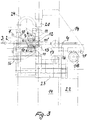
Fig. 3 zeigt den zentralen Teil der Maschine nachFig. 1 und2 in einer Seitenansicht; - die
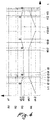
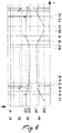
Fig. 4 - 6 sind Arbeitsdiagramme der Maschine bei verschiedenen Produktionsgeschwindigkeiten, welche die Zeit des Einsatzes verschiedener Komponenten der Maschine zeigen und das Verfahren veranschaulichen.
-
Fig. 1 a schematic overall representation of the machine in a side view, -
Fig. 2 a front view of this machine, -
Fig. 3 shows the central part of the machineFig. 1 and2 in a side view; - the
Figures 4-6 are working diagrams of the machine at different production speeds, showing the time of use of various components of the machine and illustrating the process.
Wie die
Die Querdrähte 4 können entweder nur von oben oder unten oder beidseitig an die Schar der Längsdrähte herangeführt und so Gitter mit der Lage von Querdrähten oberhalb oder unterhalb der Längsdrähte hergestellt werden. Für die Zufuhr der Querdrähte 4 wird jeweils von einer Spule 5 der aufgewickelte Draht mittels einer Abzieheinrichtung 6 abgezogen, auf die erforderliche Länge der Querdrähte 4 geschnitten und werden diese einer Übergabeeinrichtung zugeführt, die mehrere Querdrähte 4 aufnehmen kann. Die Übergabeeinrichtungen sind als quer zur Schar der Längsdrähte über bzw. unter dieser Schar angeordnete Trommeln 7 ausgebildet, von welchen eine Trommel 7 oberhalb der Schar von Längsdrähten und eine Trommel 7 unterhalb dieser Schar am stationären äußeren Rahmen 1 mitsamt einem jeweiligen Drehantrieb gelagert ist. Möglich ist auch ein gemeinsamer Drehantrieb für die obere 7 und die untere Trommel 7, der bei Bedarf von einer der Trommeln 7 getrennt werden kann und dann nur die andere Trommel 7 beaufschlagt. Die Trommeln 7 weisen an ihrer Oberfläche in ihrer Längsrichtung verlaufende Rillen 8 auf, die nach außen offen stehen. Jede Trommel 6 hat mindestens drei um ihren Umfang gleichmäßig verteilte Rillen 8, von welchen im Betrieb mindestens zwei je einen Querdraht 4 aufnehmen. Die Trommeln 7 sind intermittierend drehbar; in den Drehpausen schiebt eine hier nicht näher beschriebene Einschußeinrichtung einen Querdraht 4 von der Seite her über seine ganze Maschinenbreite hinein in eine an der Oberseite bzw. Unterseite der Trommel 7 befindliche Rille 8, worauf der Querdraht 4 in seiner endgültigen Position ober- bzw. unterhalb der Schar der Längsdrähte am Ende der Rille 8 abgebremst wird; eine derartige Trommel 7 mitsamt der nötigen Bremseinrichtung für die in die Rillen 8 eingeschossenen Querdrähte 4 ist beschrieben in der veröffentlichten
Das Abgreifen erfolgt unter Öffnen der Klappe 10 mittels einer Reihe synchron bewegter Greiffinger 11, die den Querdraht 4 darauffolgend unter Aufrechterhaltung von dessen horizontaler Querlage durch Bewegen hin zur Arbeitsebene 2 und in der Produktionsrichtung 3 in die endgültige Schweißposition bringen. Die Ausbildung der Greiffinger 11 wird weiter unten erläutert. Die Reihe der Greiffinger 11 bewegt den abgegriffenen Querdraht 4 dabei wie folgt: Zuerst wird der jeweilige Querdraht 4 entlang eines Teilstücks einer etwa elliptischen Kurvenbahn 11' in der Produktionsrichtung 3 nach vorne und unten bzw. oben in Anlage gegen die bewegte Schar der Längsdrähte gebracht. Hierauf fahren die Greiffinger 11 entlang einer kurzen geraden Strecke mit den Längsdrähten und dem zu verschweißenden Querdraht 4 mit. Beispielhaft sei angeführt, daß bei einer Produktionsgeschwindigkeit von etwa 0,35 bis 0,5 m/s die Länge dieser kurzen Strecke etwa 5 mm beträgt. Anschließend kehren die Greiffinger 11 entlang eines Teilstückes einer elliptischen Kurvenbahn wieder nach hinten und oben bzw. unten in ihre Ausgangs-Greifstellung zurück, um dort den in der nächsten Rille 8 liegenden nächsten Querdraht 4 abzugreifen.The gripping takes place by opening the
Unmittelbar nach dem Aufsetzen des Querdrahtes 4 an den Längsdrähten fahren von oben kommende Elektroden 12 mit ihren Schweißflächen an die Kreuzungsstellen des Drahtgitters, welche auf den Schweißflächen der unteren Gegenelektroden 13 aufliegen. Die zusammenwirkenden Schweißflächen werden so lange unter Zwischenanordnung der Kreuzungsstellen des Gitters gegeneinander gepreßt, bis die Schweißung nach Ablauf der schweißtechnisch erforderlichen Schweißzeit durchgeführt ist. Für eine hinreichend, den Anforderungen entsprechende feste Schweißung ist bei einer Produktionsgeschwindigkeit von beispielhaft 0,35 bis 0,5 m/s ein Mitfahrweg der Elektroden 12 und Gegenelektroden 13 von max. ca. 80 mm erforderlich.Immediately after the
Die Elektroden 12 und Gegenelektroden 13 sind an einem innenliegenden Rahmen 14 (oder auch Wagen) angeordnet, der am ortsfesten äußeren Rahmen 1 gelagert und gegenüber diesem periodisch horizontal hin- und herverfahrbar ist, wobei die Verfahrstrecke den beispielhaft genannten 80 mm entspricht. Der innenliegende, verfahrbare Rahmen 14 ist ausgeführt in Form eines Wagens, welcher mittels Rollen 16 eine Führung 17 des äußeren Rahmens 1 entlang fahrbar ist. Der Antrieb des Rahmens 14 erfolgt mittels eines motorgetriebenen Antriebsritzels 18, welches am äußeren Rahmen 1 gelagert ist und in eine am Rahmen 14 befestigte Zahnstange 19 eingreift.The
Für das Auf- und Abbewegen der Elektroden 12 sind diese am Innenliegenden Rahmen 14 vertikal geführt und mittels eines Verstellantriebes, z.B. in Form hydraulischer oder pneumatischer Zylinder-Kolben-Einrichtungen 20, verfahrbar.To move the
Die Greiffinger 11 sind nach dem in der
Der Anpreßdruck der Elektroden 121 kann konstant über den gesamten Schweißzyklus gehalten werden oder in Abhängigkeit des zu verschweißenden Materials auch einem vorbestimmten Profil folgen. Ein solches Profil kann die drei Stufen mit jeweils unterschiedlichem Anpreßdruck "Vorpressen ohne Strom", "Schweißung" und "Nachpressen" beinhalten.The contact pressure of the electrodes 121 can be kept constant over the entire welding cycle or as a function of the The material to be welded also follows a predetermined profile. Such a profile can contain the three stages with different contact pressure "pre-pressing without electricity", "welding" and "post-pressing".
Die Hebelsysteme führen zu einer in sich geschlossenen Bahn der Greiffinger 11 entlang einer wie oben beschriebenen Kurvenbahn.The lever systems lead to a self-contained path of the gripping
Die Zeichnung zeigt im Übrigen am äußeren Rahmen 1 befestigte ortsfeste Schweißtransformatoren 22, die mittels flexibler Strombänder 23 und einer am Rahmen 14 befestigten Strombrücke 24 mit den Gegenelektroden 13 bzw. den Elektroden 12 verbunden sind.The drawing also shows
Die
Die in den
Im Teildiagramm A1 ist auf der y-Achse die Geschwindigkeit der Vorschubeinrichtung für das Gitter aufgetragen und deren konstante Größe a1 ersichtlich.In partial diagram A1, the speed of the feed device for the grid is plotted on the y-axis and its constant value a1 can be seen.
Im Teildiagramm A2 ist auf der y-Achse der Vertikalweg der Greiffinger 11 beim Zubringen des Querdrahtes 4 von der Trommel 7 auf die Schar der Längsdrähte aufgetragen. Die Bewegung der Greiffinger 11 beginnt zum Zeitpunkt t1, worauf der Querdraht 4 nach Durchlaufen einer ersten Teilstrecke einer etwa elliptischen Kurvenbahn zum Zeitpunkt t3 die Schar der Längsdrähte erreicht. Hierauf fahren die Greiffinger 11 kurzzeitig bis zum Zeitpunkt t4 synchron mit dem Gitter mit und heben bei t4 wieder von diesem ab und bewegen sich sodänn weiter entlang der etwa elliptischen Kurvenbahn, bis sie zur bei t1 eingenommenen früheren Position wieder zurückkehren.In the partial diagram A2, the vertical path of the gripping
Im Teildiagramm A3 ist auf der y-Achse der Vertikalweg der oberen Schweißelektroden 12 mittels der Zylinder-Kolbeneinrichtungen 20 aufgetragen. Ausgehend von der zum Zeitpunkt t-1 eingenommenen Offenstellung a3.1 folgt eine Beschleunigung bis zum Zeitpunkt t2, wo die Gittergeschwindigkeit erreicht wird; zum Zeitpunkt t4 kommen die Schweißelektroden in der geschlossenen Stellung a3.2 unten an und halten den Querdraht 4 auf den Längsdrähten fest; zum Zeitpunkt t4 beginnt auch das Vorpressen der Kreuzungsstellen kurz vor dem zum Zeitpunkt t5 beginnenden Schweißvorgang. Vom Zeitpunkt t5 bis zum nachfolgenden Zeitpunkt t6 dauert der Schweißvorgang. Daran schließt sich ein kurzes Nachpressen der Schweißelektroden 12 bis zum Zeitpunkt t7 an; die Schweißelektroden 12 sind im Zeitraum t4 - t7 synchron mit dem Gitter mitgefahren; zum Zeitpunkt t7 heben außerdem die Schweißelektroden 12 von den Kreuzungsstellen nach oben ab und erreichen zum Zeitpunkt t9 wieder ihre Ausgangsstellung des Zeitpunktes t-1. Ab dem Zeitpunkt t12 beginnen die Schweißelektroden 12 wieder nach unten zu fahren.In the partial diagram A3, the vertical path of the
Im Teildiagramm A4 ist auf der y-Achse die Geschwindigkeit des horizontalen Hin- und Herfahrens des die oberen Schweißelektroden 12 und die unteren Gegenelektroden 13 tragenden Rahmens 14 eingetragen. Dessen maximale Geschwindigkeit in der Produktionsrichtung 3 ist mit a4.1, die Maximalgeschwindigkeit in der Gegenrichtung mit a4.2 bezeichnet. Man sieht, daß ab dem Zeitpunkt t7 die Geschwindigkeit des Rahmens 14 verzögert wird bis zum Erreichen des Umkehrpunktes zum Zeitpunkt t8 und dann in der Gegenrichtung wieder beschleunigt wird bis zum Zeit punkt t10, zu dem die maximale Rückfahrtgeschwindigkeit erreicht ist. Zum Zeitpunkt t11 beginnt die Verzögerung der Rückfahrt des Rahmens 14, der ab dem Zeitpunkt t13 wieder in der Produktionsrichtung 3 fährt.In partial diagram A4, the y-axis shows the speed of the horizontal back and forth movement of the
Der in den
Claims (10)
- Mesh welding machine operating continuously according to the electrical resistance principle, comprising a stationary outer longitudinal frame (1), on which, in a manner resting thereon, a horizontal set of parallel longitudinal wires can be moved continuously in a production direction (3) by means of a feeding device, and comprising a removal apparatus (6), by means of which cross wires (4) can be removed from a coil or rings (5) and fed to a transfer device extending transversely to the set of longitudinal wires, in which transfer device a plurality of cross wires (4) can be received and, from there, can be conveyed one after another in turn towards the longitudinal wires and brought into contact with said longitudinal wires in a correct orientation according to the pitch of the cross wires and can be set down there, and comprising electrodes (12) and counter electrodes (13), the weld surfaces of which can be pressed against one another so as to have points of intersection therebetween, which points of intersection are formed between the longitudinal wires and the cross wires (4), both the upper electrodes (12) and the lower counter electrodes (13) being arranged on an inner frame (14) which is mounted on the stationary frame (1) and is movable back and forth periodically in the longitudinal direction relative to said stationary frame, and the upper electrodes (12) being mounted on the movable frame (14) so as to be able to move from an upper position downwards onto the points of intersection that rest on the lower counter electrodes (13), said upper electrodes reaching a lower first position of the start of the welding process so as to be in contact with the points of intersection and then, by moving the frame (14) in the longitudinal direction together with the lower counter electrodes (13) while maintaining contact pressure, traveling synchronously with the mesh into a second position of the end of the welding process, which second position is at the same height level and located downstream with respect to a direction of flow, and then, by moving the inner frame (14) back, the electrodes (12) and the counter electrodes (13) returning to their earlier positions with respect to the longitudinal direction, while the upper electrodes (12) can be moved first vertically upwards again and then downwards into the earlier, lower first position of the start of the welding process on the following cross wire(s) (4), it being possible to bring the cross wires (4) into contact with the set of longitudinal wires in the correct orientation by means of gripping fingers (11), characterised in that the gripping fingers (11) provided for each of the weld points can travel to the transfer device which is intended for receiving the cross wires (4) and receives a plurality of cross wires (4) arriving from the removal apparatus (6), and said fingers then can be moved together with a received cross wire (4) towards the points of intersection until the cross wire (4) contacts the points of intersection at a time immediately before the upper electrodes (12), and the gripping fingers (11) then travel, by means of the movable frame (14), first alone along a first section before welding begins and then together with the electrodes (12) and the counter electrodes (13) along another section of the horizontal path travelled by said electrodes synchronously with the longitudinal wires of the mesh to be formed, whereupon the synchronous travel of the electrodes (12) and the counter electrodes (13) can be continued until welding is completed.
- Mesh welding machine according to claim 1, characterised in that the transfer device receiving a plurality of cross wires (4) arriving from the removal apparatus (6) is in the form of a drum (7) that extends transversely to the set of longitudinal wires above or below said wires, which drum has, on its surface, grooves (8) extending in the longitudinal direction, in which grooves (8), after each rotation of the drum (7), a plurality of cross wires (4) can be received and, from there, picked off said drum one by one by means of the gripping fingers (11).
- Mesh welding machine according to either claim 1 or claim 2, characterised in that the coils (5), the removal apparatuses (6), the drums (7), the gripping fingers (11) and the welding transformers (22), which transformers are necessary for welding according to the electrical resistance principle, are mounted on the stationary outer frame (1).
- Mesh welding machine according to any of claims 1 to 3, characterised in that power supply devices (24) provided for supplying power from the stationary transformers (22) to the electrodes (12) and the counter electrodes (13) are in the form of flexible conductor lines or power cables (23) across a portion extending as far as the movable frame (14).
- Mesh welding machine according to any of claims 1 to 4, characterised in that the movement path of the frame (14) which can be moved back and forth in the longitudinal direction is the same as the common horizontal movement path of the upper electrodes (12) and the lower counter electrodes (13) during the welding process and is approximately 30 to at most 80 mm long.
- Mesh welding machine according to claim 1, characterised in that the first section of the horizontal movement path covered jointly by the electrodes (12) and the counter electrodes (13) during the welding process, which section is covered by the gripping fingers (11), also synchronously with the points of intersection, is approximately 3 to 10 mm long.
- Mesh welding machine according to either claim 5 or claim 6, characterised in that, at a production speed of the mesh of approximately 0.35 to 0.5 m/s, the short common travel distance of the gripping fingers (11) is approximately 5 mm and the further common travel distance of the electrodes (12) and the counter electrodes (13) is approximately 80 mm long.
- Mesh welding machine according to claim 2, characterised in that the cross wires (4) located in the grooves (8) in the drums (7), before being picked off by means of the gripping fingers (11), are prevented from falling out of the particular groove (8) by means of pivotable flaps (10).
- Mesh welding machine according to any of claims 1 to 8, characterised in that the horizontal movement of the movable frame (14) is carried out by means of a motor-driven pinion (18) which engages in a rack (19) fastened to the movable frame (14).
- Mesh welding machine according to any of claims 1 to 9, characterised in that hydraulic or pneumatic cylinder-piston devices (20) are arranged on the horizontally movable frame (14) in order to move the electrodes (12) up and down said frame.
Applications Claiming Priority (2)
| Application Number | Priority Date | Filing Date | Title |
|---|---|---|---|
| ATA566/2016A AT519106B1 (en) | 2016-12-14 | 2016-12-14 | Grid welding machine and method for producing wire mesh |
| PCT/AT2017/000070 WO2018107188A1 (en) | 2016-12-14 | 2017-10-04 | Mesh welding machine and method for producing wire meshes |
Publications (2)
| Publication Number | Publication Date |
|---|---|
| EP3554752A1 EP3554752A1 (en) | 2019-10-23 |
| EP3554752B1 true EP3554752B1 (en) | 2020-12-16 |
Family
ID=60153002
Family Applications (1)
| Application Number | Title | Priority Date | Filing Date |
|---|---|---|---|
| EP17787298.3A Active EP3554752B1 (en) | 2016-12-14 | 2017-10-04 | Grid welding machine |
Country Status (12)
| Country | Link |
|---|---|
| US (1) | US10717144B2 (en) |
| EP (1) | EP3554752B1 (en) |
| JP (1) | JP7073395B2 (en) |
| CN (1) | CN109922916A (en) |
| AT (1) | AT519106B1 (en) |
| AU (1) | AU2017374521A1 (en) |
| BR (1) | BR112019006209A2 (en) |
| ES (1) | ES2852003T3 (en) |
| RU (1) | RU2741580C2 (en) |
| TW (1) | TWI661877B (en) |
| WO (1) | WO2018107188A1 (en) |
| ZA (1) | ZA201903836B (en) |
Families Citing this family (4)
| Publication number | Priority date | Publication date | Assignee | Title |
|---|---|---|---|---|
| EP3708287A1 (en) | 2019-03-15 | 2020-09-16 | Ideal-Werk C. & E. Jungeblodt GmbH & Co.KG | Carrier for a welding machine, in particular for a grid welding machine |
| CN110595919B (en) * | 2019-07-19 | 2022-04-29 | 江阴市建鑫金属有限公司 | Method for testing fatigue strength of steel bar welded mesh |
| CN112809238B (en) * | 2021-02-09 | 2022-12-16 | 上海市机械施工集团有限公司 | Reinforcing mesh welding method |
| CN113020767B (en) * | 2021-03-18 | 2022-08-02 | 山东建筑大学 | Manipulator for welding steel reinforcement framework and use method thereof |
Family Cites Families (23)
| Publication number | Priority date | Publication date | Assignee | Title |
|---|---|---|---|---|
| FR1193844A (en) | 1959-11-05 | |||
| US2725081A (en) * | 1951-12-26 | 1955-11-29 | Northwestern Steel & Wire Comp | Welded wire mesh fabricating machine |
| AT213205B (en) * | 1959-04-24 | 1961-01-25 | Evg Entwicklung Verwert Ges | Cross wire feeding device for mesh welding machines |
| AT307210B (en) * | 1969-07-15 | 1973-05-10 | Evg Entwicklung Verwert Ges | Method and device for the production of welded wire mesh |
| JPS4847816U (en) * | 1971-10-05 | 1973-06-23 | ||
| US3961153A (en) * | 1974-05-24 | 1976-06-01 | Trw Inc. | Machine for fabricating a wire network |
| AT346668B (en) | 1976-02-24 | 1978-11-27 | Evg Entwicklung Verwert Ges | MULTI-SPOT WELDING MACHINE FOR THE PRODUCTION OF A MESH MESH FROM AN INCLINED TO THE LONGITUDINAL DIRECTION OF THE MESH |
| AT357005B (en) * | 1977-04-18 | 1980-06-10 | Evg Entwicklung Verwert Ges | GRID WELDING MACHINE WORKING ON THE ELECTRIC RESISTANCE METHOD |
| US4221951A (en) * | 1978-10-10 | 1980-09-09 | Connolly James D | Screen welding machine |
| AT379973B (en) | 1984-01-13 | 1986-03-25 | Evg Entwicklung Verwert Ges | GRID WELDING MACHINE WORKING ON THE ELECTRIC RESISTANCE METHOD |
| AT384969B (en) * | 1986-04-02 | 1988-02-10 | Evg Entwicklung Verwert Ges | MULTIPLE POINT RESISTANCE WELDING MACHINE |
| SU1526941A1 (en) * | 1987-12-14 | 1989-12-07 | Курский завод "Аккумулятор" | Apparatus for welding nets |
| CN2418996Y (en) * | 1999-10-15 | 2001-02-14 | 王英顺 | Wire feeding mechanism for welding net |
| RU2248264C2 (en) * | 2002-10-15 | 2005-03-20 | ОАО "Машиностроительный завод "ЗиО-Подольск" | Method of and plant for manufacture of flat wire screens |
| AT413341B (en) | 2004-03-25 | 2006-02-15 | Evg Entwicklung Verwert Ges | DEVICE FOR BREAKING AND EJECTING STAINLESS MATERIAL |
| RU2270082C1 (en) * | 2004-06-15 | 2006-02-20 | Андрей Борисович Белов | Automatic line for producing wire gauzes |
| TWM262298U (en) * | 2004-06-29 | 2005-04-21 | Yun Li Rong Machinery Co Ltd | Improved spot welding apparatus for metal net |
| DE102007002856B4 (en) * | 2007-01-15 | 2012-02-09 | Edag Gmbh & Co. Kgaa | Device for flanging and welding or soldering of components |
| CN201361761Y (en) * | 2009-03-18 | 2009-12-16 | 招远市泉港机械有限公司 | Grid plate press welder |
| JP2011125923A (en) * | 2009-12-21 | 2011-06-30 | Honda Motor Co Ltd | Installation structure and installation method for bearing |
| CN102699241B (en) * | 2012-05-25 | 2014-07-23 | 建科机械(天津)股份有限公司 | Multi-specification horizontal wire blanking mechanism for wire mesh welding machine |
| CN104209432B (en) * | 2013-07-30 | 2016-03-23 | 河北骄阳丝网设备有限责任公司 | Full-automatic reinforcing mesh welding production line |
| AT515914B1 (en) | 2014-08-08 | 2016-01-15 | Evg Entwicklung Verwert Ges | Wire mesh welding machine |
-
2016
- 2016-12-14 AT ATA566/2016A patent/AT519106B1/en active
-
2017
- 2017-10-04 US US16/342,395 patent/US10717144B2/en active Active
- 2017-10-04 JP JP2019553596A patent/JP7073395B2/en active Active
- 2017-10-04 EP EP17787298.3A patent/EP3554752B1/en active Active
- 2017-10-04 AU AU2017374521A patent/AU2017374521A1/en not_active Abandoned
- 2017-10-04 CN CN201780069149.7A patent/CN109922916A/en active Pending
- 2017-10-04 ES ES17787298T patent/ES2852003T3/en active Active
- 2017-10-04 WO PCT/AT2017/000070 patent/WO2018107188A1/en unknown
- 2017-10-04 BR BR112019006209A patent/BR112019006209A2/en not_active Application Discontinuation
- 2017-10-04 RU RU2019117424A patent/RU2741580C2/en active
- 2017-10-12 TW TW106134931A patent/TWI661877B/en not_active IP Right Cessation
-
2019
- 2019-06-13 ZA ZA2019/03836A patent/ZA201903836B/en unknown
Non-Patent Citations (1)
| Title |
|---|
| None * |
Also Published As
| Publication number | Publication date |
|---|---|
| CN109922916A (en) | 2019-06-21 |
| AT519106A4 (en) | 2018-04-15 |
| US20190337083A1 (en) | 2019-11-07 |
| AT519106B1 (en) | 2018-04-15 |
| AU2017374521A1 (en) | 2019-06-27 |
| JP7073395B2 (en) | 2022-05-23 |
| TWI661877B (en) | 2019-06-11 |
| ES2852003T3 (en) | 2021-09-10 |
| RU2019117424A3 (en) | 2020-12-15 |
| RU2019117424A (en) | 2020-12-07 |
| BR112019006209A2 (en) | 2019-06-18 |
| TW201821176A (en) | 2018-06-16 |
| EP3554752A1 (en) | 2019-10-23 |
| RU2741580C2 (en) | 2021-01-27 |
| US10717144B2 (en) | 2020-07-21 |
| ZA201903836B (en) | 2022-05-25 |
| WO2018107188A1 (en) | 2018-06-21 |
| JP2020513330A (en) | 2020-05-14 |
Similar Documents
| Publication | Publication Date | Title |
|---|---|---|
| EP3554752B1 (en) | Grid welding machine | |
| EP0371956B1 (en) | Method and installation for feeding longitudinal elements to a welding machine for making grids or gratings | |
| DE102009042384B4 (en) | A method and apparatus for applying a unidirectional fiber ply to a moving support and method of making a multiaxial fabric | |
| DE2121426B2 (en) | Method and device for changing bobbins in textile machines | |
| DE2835308A1 (en) | METHOD AND DEVICE FOR BANDEROLATING THIN SHEET LEAF | |
| DE1565777B2 (en) | Process for electrical discharge machining and apparatus for carrying out the process | |
| WO2018162237A1 (en) | Device and method for severing a strip into a plurality of individual strip pieces | |
| DE2522970C3 (en) | Device for feeding cut wires to a wire processing machine, in particular a mesh welding machine | |
| EP0622136B1 (en) | Device for the production of reinforcement meshes for concrete panels | |
| EP2173503B1 (en) | Method and system for producing wire lattice mats | |
| DE3121660A1 (en) | Method and device for machining insulated wire | |
| DE2051354C3 (en) | Device for feeding line wires to mesh welding machines | |
| DE505061C (en) | Method for regulating the speed of moving bars in connection with a device for separating and sorting | |
| DE3718886C2 (en) | ||
| DE102014106106B4 (en) | Coating device and method for coating a workpiece surface | |
| DE102018114579B3 (en) | Method and device for burr-free cutting of a wire and a correspondingly separated piece of wire and hairpin | |
| DE1290031B (en) | Multi-station processing machine for the automatic production of threaded pins | |
| DE2608160C3 (en) | Device for releasing cut wires from a disordered wire bundle, especially when feeding the wires to a processing machine | |
| DE1917852C3 (en) | Method of making wire mesh | |
| DE857622C (en) | Dishwasher | |
| EP3126071A1 (en) | Advancing and straightening device | |
| AT406348B (en) | MAT TRANSPORTER | |
| EP0815982B1 (en) | Wire guiding device for the treatment of wire ends | |
| DE2212291A1 (en) | Method and device for the manufacture of cages from reinforcing bars | |
| DE3836974A1 (en) | METHOD AND DEVICE FOR FOLDING AND LAYING TEXTILE FILMS IN STACKS |
Legal Events
| Date | Code | Title | Description |
|---|---|---|---|
| STAA | Information on the status of an ep patent application or granted ep patent |
Free format text: STATUS: UNKNOWN |
|
| STAA | Information on the status of an ep patent application or granted ep patent |
Free format text: STATUS: THE INTERNATIONAL PUBLICATION HAS BEEN MADE |
|
| PUAI | Public reference made under article 153(3) epc to a published international application that has entered the european phase |
Free format text: ORIGINAL CODE: 0009012 |
|
| STAA | Information on the status of an ep patent application or granted ep patent |
Free format text: STATUS: REQUEST FOR EXAMINATION WAS MADE |
|
| 17P | Request for examination filed |
Effective date: 20190404 |
|
| AK | Designated contracting states |
Kind code of ref document: A1 Designated state(s): AL AT BE BG CH CY CZ DE DK EE ES FI FR GB GR HR HU IE IS IT LI LT LU LV MC MK MT NL NO PL PT RO RS SE SI SK SM TR |
|
| AX | Request for extension of the european patent |
Extension state: BA ME |
|
| DAV | Request for validation of the european patent (deleted) | ||
| DAX | Request for extension of the european patent (deleted) | ||
| GRAP | Despatch of communication of intention to grant a patent |
Free format text: ORIGINAL CODE: EPIDOSNIGR1 |
|
| STAA | Information on the status of an ep patent application or granted ep patent |
Free format text: STATUS: GRANT OF PATENT IS INTENDED |
|
| INTG | Intention to grant announced |
Effective date: 20200805 |
|
| GRAS | Grant fee paid |
Free format text: ORIGINAL CODE: EPIDOSNIGR3 |
|
| GRAA | (expected) grant |
Free format text: ORIGINAL CODE: 0009210 |
|
| STAA | Information on the status of an ep patent application or granted ep patent |
Free format text: STATUS: THE PATENT HAS BEEN GRANTED |
|
| AK | Designated contracting states |
Kind code of ref document: B1 Designated state(s): AL AT BE BG CH CY CZ DE DK EE ES FI FR GB GR HR HU IE IS IT LI LT LU LV MC MK MT NL NO PL PT RO RS SE SI SK SM TR |
|
| REG | Reference to a national code |
Ref country code: GB Ref legal event code: FG4D Free format text: NOT ENGLISH |
|
| REG | Reference to a national code |
Ref country code: IE Ref legal event code: FG4D Free format text: LANGUAGE OF EP DOCUMENT: GERMAN |
|
| REG | Reference to a national code |
Ref country code: DE Ref legal event code: R096 Ref document number: 502017008720 Country of ref document: DE |
|
| REG | Reference to a national code |
Ref country code: AT Ref legal event code: REF Ref document number: 1345142 Country of ref document: AT Kind code of ref document: T Effective date: 20210115 Ref country code: CH Ref legal event code: NV Representative=s name: ISLER AND PEDRAZZINI AG, CH |
|
| REG | Reference to a national code |
Ref country code: NL Ref legal event code: FP |
|
| REG | Reference to a national code |
Ref country code: GR Ref legal event code: EP Ref document number: 20210400521 Country of ref document: GR Effective date: 20210416 |
|
| REG | Reference to a national code |
Ref country code: SK Ref legal event code: T3 Ref document number: E 36661 Country of ref document: SK |
|
| PG25 | Lapsed in a contracting state [announced via postgrant information from national office to epo] |
Ref country code: NO Free format text: LAPSE BECAUSE OF FAILURE TO SUBMIT A TRANSLATION OF THE DESCRIPTION OR TO PAY THE FEE WITHIN THE PRESCRIBED TIME-LIMIT Effective date: 20210316 Ref country code: FI Free format text: LAPSE BECAUSE OF FAILURE TO SUBMIT A TRANSLATION OF THE DESCRIPTION OR TO PAY THE FEE WITHIN THE PRESCRIBED TIME-LIMIT Effective date: 20201216 Ref country code: RS Free format text: LAPSE BECAUSE OF FAILURE TO SUBMIT A TRANSLATION OF THE DESCRIPTION OR TO PAY THE FEE WITHIN THE PRESCRIBED TIME-LIMIT Effective date: 20201216 |
|
| PG25 | Lapsed in a contracting state [announced via postgrant information from national office to epo] |
Ref country code: LV Free format text: LAPSE BECAUSE OF FAILURE TO SUBMIT A TRANSLATION OF THE DESCRIPTION OR TO PAY THE FEE WITHIN THE PRESCRIBED TIME-LIMIT Effective date: 20201216 Ref country code: SE Free format text: LAPSE BECAUSE OF FAILURE TO SUBMIT A TRANSLATION OF THE DESCRIPTION OR TO PAY THE FEE WITHIN THE PRESCRIBED TIME-LIMIT Effective date: 20201216 Ref country code: BG Free format text: LAPSE BECAUSE OF FAILURE TO SUBMIT A TRANSLATION OF THE DESCRIPTION OR TO PAY THE FEE WITHIN THE PRESCRIBED TIME-LIMIT Effective date: 20210316 |
|
| PG25 | Lapsed in a contracting state [announced via postgrant information from national office to epo] |
Ref country code: HR Free format text: LAPSE BECAUSE OF FAILURE TO SUBMIT A TRANSLATION OF THE DESCRIPTION OR TO PAY THE FEE WITHIN THE PRESCRIBED TIME-LIMIT Effective date: 20201216 |
|
| REG | Reference to a national code |
Ref country code: LT Ref legal event code: MG9D |
|
| PG25 | Lapsed in a contracting state [announced via postgrant information from national office to epo] |
Ref country code: SM Free format text: LAPSE BECAUSE OF FAILURE TO SUBMIT A TRANSLATION OF THE DESCRIPTION OR TO PAY THE FEE WITHIN THE PRESCRIBED TIME-LIMIT Effective date: 20201216 Ref country code: CZ Free format text: LAPSE BECAUSE OF FAILURE TO SUBMIT A TRANSLATION OF THE DESCRIPTION OR TO PAY THE FEE WITHIN THE PRESCRIBED TIME-LIMIT Effective date: 20201216 Ref country code: EE Free format text: LAPSE BECAUSE OF FAILURE TO SUBMIT A TRANSLATION OF THE DESCRIPTION OR TO PAY THE FEE WITHIN THE PRESCRIBED TIME-LIMIT Effective date: 20201216 Ref country code: LT Free format text: LAPSE BECAUSE OF FAILURE TO SUBMIT A TRANSLATION OF THE DESCRIPTION OR TO PAY THE FEE WITHIN THE PRESCRIBED TIME-LIMIT Effective date: 20201216 Ref country code: RO Free format text: LAPSE BECAUSE OF FAILURE TO SUBMIT A TRANSLATION OF THE DESCRIPTION OR TO PAY THE FEE WITHIN THE PRESCRIBED TIME-LIMIT Effective date: 20201216 Ref country code: PT Free format text: LAPSE BECAUSE OF FAILURE TO SUBMIT A TRANSLATION OF THE DESCRIPTION OR TO PAY THE FEE WITHIN THE PRESCRIBED TIME-LIMIT Effective date: 20210416 |
|
| PG25 | Lapsed in a contracting state [announced via postgrant information from national office to epo] |
Ref country code: PL Free format text: LAPSE BECAUSE OF FAILURE TO SUBMIT A TRANSLATION OF THE DESCRIPTION OR TO PAY THE FEE WITHIN THE PRESCRIBED TIME-LIMIT Effective date: 20201216 |
|
| REG | Reference to a national code |
Ref country code: DE Ref legal event code: R097 Ref document number: 502017008720 Country of ref document: DE |
|
| PG25 | Lapsed in a contracting state [announced via postgrant information from national office to epo] |
Ref country code: IS Free format text: LAPSE BECAUSE OF FAILURE TO SUBMIT A TRANSLATION OF THE DESCRIPTION OR TO PAY THE FEE WITHIN THE PRESCRIBED TIME-LIMIT Effective date: 20210416 |
|
| PLBE | No opposition filed within time limit |
Free format text: ORIGINAL CODE: 0009261 |
|
| STAA | Information on the status of an ep patent application or granted ep patent |
Free format text: STATUS: NO OPPOSITION FILED WITHIN TIME LIMIT |
|
| PG25 | Lapsed in a contracting state [announced via postgrant information from national office to epo] |
Ref country code: AL Free format text: LAPSE BECAUSE OF FAILURE TO SUBMIT A TRANSLATION OF THE DESCRIPTION OR TO PAY THE FEE WITHIN THE PRESCRIBED TIME-LIMIT Effective date: 20201216 |
|
| 26N | No opposition filed |
Effective date: 20210917 |
|
| PG25 | Lapsed in a contracting state [announced via postgrant information from national office to epo] |
Ref country code: DK Free format text: LAPSE BECAUSE OF FAILURE TO SUBMIT A TRANSLATION OF THE DESCRIPTION OR TO PAY THE FEE WITHIN THE PRESCRIBED TIME-LIMIT Effective date: 20201216 |
|
| PG25 | Lapsed in a contracting state [announced via postgrant information from national office to epo] |
Ref country code: SI Free format text: LAPSE BECAUSE OF FAILURE TO SUBMIT A TRANSLATION OF THE DESCRIPTION OR TO PAY THE FEE WITHIN THE PRESCRIBED TIME-LIMIT Effective date: 20201216 |
|
| PG25 | Lapsed in a contracting state [announced via postgrant information from national office to epo] |
Ref country code: IS Free format text: LAPSE BECAUSE OF FAILURE TO SUBMIT A TRANSLATION OF THE DESCRIPTION OR TO PAY THE FEE WITHIN THE PRESCRIBED TIME-LIMIT Effective date: 20210416 |
|
| REG | Reference to a national code |
Ref country code: SK Ref legal event code: MM4A Ref document number: E 36661 Country of ref document: SK Effective date: 20211004 |
|
| REG | Reference to a national code |
Ref country code: BE Ref legal event code: MM Effective date: 20211031 |
|
| PG25 | Lapsed in a contracting state [announced via postgrant information from national office to epo] |
Ref country code: MC Free format text: LAPSE BECAUSE OF FAILURE TO SUBMIT A TRANSLATION OF THE DESCRIPTION OR TO PAY THE FEE WITHIN THE PRESCRIBED TIME-LIMIT Effective date: 20201216 |
|
| PG25 | Lapsed in a contracting state [announced via postgrant information from national office to epo] |
Ref country code: SK Free format text: LAPSE BECAUSE OF NON-PAYMENT OF DUE FEES Effective date: 20211004 Ref country code: LU Free format text: LAPSE BECAUSE OF NON-PAYMENT OF DUE FEES Effective date: 20211004 Ref country code: BE Free format text: LAPSE BECAUSE OF NON-PAYMENT OF DUE FEES Effective date: 20211031 |
|
| PG25 | Lapsed in a contracting state [announced via postgrant information from national office to epo] |
Ref country code: IE Free format text: LAPSE BECAUSE OF NON-PAYMENT OF DUE FEES Effective date: 20211004 |
|
| PG25 | Lapsed in a contracting state [announced via postgrant information from national office to epo] |
Ref country code: CY Free format text: LAPSE BECAUSE OF FAILURE TO SUBMIT A TRANSLATION OF THE DESCRIPTION OR TO PAY THE FEE WITHIN THE PRESCRIBED TIME-LIMIT Effective date: 20201216 |
|
| PG25 | Lapsed in a contracting state [announced via postgrant information from national office to epo] |
Ref country code: HU Free format text: LAPSE BECAUSE OF FAILURE TO SUBMIT A TRANSLATION OF THE DESCRIPTION OR TO PAY THE FEE WITHIN THE PRESCRIBED TIME-LIMIT; INVALID AB INITIO Effective date: 20171004 |
|
| PGFP | Annual fee paid to national office [announced via postgrant information from national office to epo] |
Ref country code: NL Payment date: 20230919 Year of fee payment: 7 Ref country code: GB Payment date: 20230914 Year of fee payment: 7 |
|
| PGFP | Annual fee paid to national office [announced via postgrant information from national office to epo] |
Ref country code: GR Payment date: 20230907 Year of fee payment: 7 |
|
| REG | Reference to a national code |
Ref country code: AT Ref legal event code: MM01 Ref document number: 1345142 Country of ref document: AT Kind code of ref document: T Effective date: 20221004 |
|
| PGFP | Annual fee paid to national office [announced via postgrant information from national office to epo] |
Ref country code: ES Payment date: 20231102 Year of fee payment: 7 |
|
| PG25 | Lapsed in a contracting state [announced via postgrant information from national office to epo] |
Ref country code: AT Free format text: LAPSE BECAUSE OF NON-PAYMENT OF DUE FEES Effective date: 20221004 |
|
| PGFP | Annual fee paid to national office [announced via postgrant information from national office to epo] |
Ref country code: IT Payment date: 20231023 Year of fee payment: 7 Ref country code: FR Payment date: 20231026 Year of fee payment: 7 Ref country code: DE Payment date: 20230918 Year of fee payment: 7 Ref country code: CH Payment date: 20231101 Year of fee payment: 7 |