EP1587702B1 - Vehicule automobile equipe d'un moteur a combustion interne et d'un dispositif d'alimentation en energie auxiliaire - Google Patents
Vehicule automobile equipe d'un moteur a combustion interne et d'un dispositif d'alimentation en energie auxiliaire Download PDFInfo
- Publication number
- EP1587702B1 EP1587702B1 EP03769213A EP03769213A EP1587702B1 EP 1587702 B1 EP1587702 B1 EP 1587702B1 EP 03769213 A EP03769213 A EP 03769213A EP 03769213 A EP03769213 A EP 03769213A EP 1587702 B1 EP1587702 B1 EP 1587702B1
- Authority
- EP
- European Patent Office
- Prior art keywords
- heat exchanger
- internal combustion
- combustion engine
- motor vehicle
- fuel cell
- Prior art date
- Legal status (The legal status is an assumption and is not a legal conclusion. Google has not performed a legal analysis and makes no representation as to the accuracy of the status listed.)
- Expired - Lifetime
Links
- 238000002485 combustion reaction Methods 0.000 title claims abstract description 48
- 239000000446 fuel Substances 0.000 claims abstract description 49
- 238000001816 cooling Methods 0.000 claims abstract description 30
- 238000010438 heat treatment Methods 0.000 claims abstract description 27
- 239000000463 material Substances 0.000 claims abstract description 7
- 239000002826 coolant Substances 0.000 claims description 35
- 239000003921 oil Substances 0.000 claims description 27
- 239000010705 motor oil Substances 0.000 claims description 24
- 239000012208 gear oil Substances 0.000 claims description 7
- 230000001105 regulatory effect Effects 0.000 claims 1
- 230000004907 flux Effects 0.000 abstract 2
- 230000005540 biological transmission Effects 0.000 description 26
- 238000004378 air conditioning Methods 0.000 description 5
- 239000002918 waste heat Substances 0.000 description 5
- 239000008367 deionised water Substances 0.000 description 4
- 229910021641 deionized water Inorganic materials 0.000 description 4
- 229910001220 stainless steel Inorganic materials 0.000 description 4
- 239000010935 stainless steel Substances 0.000 description 4
- XLYOFNOQVPJJNP-UHFFFAOYSA-N water Chemical compound O XLYOFNOQVPJJNP-UHFFFAOYSA-N 0.000 description 4
- 239000003054 catalyst Substances 0.000 description 2
- 239000003344 environmental pollutant Substances 0.000 description 2
- 239000007789 gas Substances 0.000 description 2
- 238000000034 method Methods 0.000 description 2
- 231100000719 pollutant Toxicity 0.000 description 2
- 239000000126 substance Substances 0.000 description 2
- 239000000498 cooling water Substances 0.000 description 1
- 239000000284 extract Substances 0.000 description 1
- 239000010687 lubricating oil Substances 0.000 description 1
- 238000013021 overheating Methods 0.000 description 1
- 238000010257 thawing Methods 0.000 description 1
Images

Classifications
-
- F—MECHANICAL ENGINEERING; LIGHTING; HEATING; WEAPONS; BLASTING
- F01—MACHINES OR ENGINES IN GENERAL; ENGINE PLANTS IN GENERAL; STEAM ENGINES
- F01P—COOLING OF MACHINES OR ENGINES IN GENERAL; COOLING OF INTERNAL-COMBUSTION ENGINES
- F01P7/00—Controlling of coolant flow
- F01P7/14—Controlling of coolant flow the coolant being liquid
- F01P7/16—Controlling of coolant flow the coolant being liquid by thermostatic control
- F01P7/165—Controlling of coolant flow the coolant being liquid by thermostatic control characterised by systems with two or more loops
-
- B—PERFORMING OPERATIONS; TRANSPORTING
- B60—VEHICLES IN GENERAL
- B60K—ARRANGEMENT OR MOUNTING OF PROPULSION UNITS OR OF TRANSMISSIONS IN VEHICLES; ARRANGEMENT OR MOUNTING OF PLURAL DIVERSE PRIME-MOVERS IN VEHICLES; AUXILIARY DRIVES FOR VEHICLES; INSTRUMENTATION OR DASHBOARDS FOR VEHICLES; ARRANGEMENTS IN CONNECTION WITH COOLING, AIR INTAKE, GAS EXHAUST OR FUEL SUPPLY OF PROPULSION UNITS IN VEHICLES
- B60K6/00—Arrangement or mounting of plural diverse prime-movers for mutual or common propulsion, e.g. hybrid propulsion systems comprising electric motors and internal combustion engines ; Control systems therefor, i.e. systems controlling two or more prime movers, or controlling one of these prime movers and any of the transmission, drive or drive units Informative references: mechanical gearings with secondary electric drive F16H3/72; arrangements for handling mechanical energy structurally associated with the dynamo-electric machine H02K7/00; machines comprising structurally interrelated motor and generator parts H02K51/00; dynamo-electric machines not otherwise provided for in H02K see H02K99/00
- B60K6/20—Arrangement or mounting of plural diverse prime-movers for mutual or common propulsion, e.g. hybrid propulsion systems comprising electric motors and internal combustion engines ; Control systems therefor, i.e. systems controlling two or more prime movers, or controlling one of these prime movers and any of the transmission, drive or drive units Informative references: mechanical gearings with secondary electric drive F16H3/72; arrangements for handling mechanical energy structurally associated with the dynamo-electric machine H02K7/00; machines comprising structurally interrelated motor and generator parts H02K51/00; dynamo-electric machines not otherwise provided for in H02K see H02K99/00 the prime-movers consisting of electric motors and internal combustion engines, e.g. HEVs
- B60K6/22—Arrangement or mounting of plural diverse prime-movers for mutual or common propulsion, e.g. hybrid propulsion systems comprising electric motors and internal combustion engines ; Control systems therefor, i.e. systems controlling two or more prime movers, or controlling one of these prime movers and any of the transmission, drive or drive units Informative references: mechanical gearings with secondary electric drive F16H3/72; arrangements for handling mechanical energy structurally associated with the dynamo-electric machine H02K7/00; machines comprising structurally interrelated motor and generator parts H02K51/00; dynamo-electric machines not otherwise provided for in H02K see H02K99/00 the prime-movers consisting of electric motors and internal combustion engines, e.g. HEVs characterised by apparatus, components or means specially adapted for HEVs
- B60K6/32—Arrangement or mounting of plural diverse prime-movers for mutual or common propulsion, e.g. hybrid propulsion systems comprising electric motors and internal combustion engines ; Control systems therefor, i.e. systems controlling two or more prime movers, or controlling one of these prime movers and any of the transmission, drive or drive units Informative references: mechanical gearings with secondary electric drive F16H3/72; arrangements for handling mechanical energy structurally associated with the dynamo-electric machine H02K7/00; machines comprising structurally interrelated motor and generator parts H02K51/00; dynamo-electric machines not otherwise provided for in H02K see H02K99/00 the prime-movers consisting of electric motors and internal combustion engines, e.g. HEVs characterised by apparatus, components or means specially adapted for HEVs characterised by the fuel cells
-
- F—MECHANICAL ENGINEERING; LIGHTING; HEATING; WEAPONS; BLASTING
- F01—MACHINES OR ENGINES IN GENERAL; ENGINE PLANTS IN GENERAL; STEAM ENGINES
- F01M—LUBRICATING OF MACHINES OR ENGINES IN GENERAL; LUBRICATING INTERNAL COMBUSTION ENGINES; CRANKCASE VENTILATING
- F01M5/00—Heating, cooling, or controlling temperature of lubricant; Lubrication means facilitating engine starting
- F01M5/02—Conditioning lubricant for aiding engine starting, e.g. heating
- F01M5/021—Conditioning lubricant for aiding engine starting, e.g. heating by heating
-
- F—MECHANICAL ENGINEERING; LIGHTING; HEATING; WEAPONS; BLASTING
- F01—MACHINES OR ENGINES IN GENERAL; ENGINE PLANTS IN GENERAL; STEAM ENGINES
- F01P—COOLING OF MACHINES OR ENGINES IN GENERAL; COOLING OF INTERNAL-COMBUSTION ENGINES
- F01P3/00—Liquid cooling
- F01P3/20—Cooling circuits not specific to a single part of engine or machine
-
- H—ELECTRICITY
- H01—ELECTRIC ELEMENTS
- H01M—PROCESSES OR MEANS, e.g. BATTERIES, FOR THE DIRECT CONVERSION OF CHEMICAL ENERGY INTO ELECTRICAL ENERGY
- H01M8/00—Fuel cells; Manufacture thereof
- H01M8/04—Auxiliary arrangements, e.g. for control of pressure or for circulation of fluids
- H01M8/04007—Auxiliary arrangements, e.g. for control of pressure or for circulation of fluids related to heat exchange
- H01M8/04029—Heat exchange using liquids
-
- F—MECHANICAL ENGINEERING; LIGHTING; HEATING; WEAPONS; BLASTING
- F01—MACHINES OR ENGINES IN GENERAL; ENGINE PLANTS IN GENERAL; STEAM ENGINES
- F01P—COOLING OF MACHINES OR ENGINES IN GENERAL; COOLING OF INTERNAL-COMBUSTION ENGINES
- F01P3/00—Liquid cooling
- F01P2003/001—Cooling liquid
-
- F—MECHANICAL ENGINEERING; LIGHTING; HEATING; WEAPONS; BLASTING
- F01—MACHINES OR ENGINES IN GENERAL; ENGINE PLANTS IN GENERAL; STEAM ENGINES
- F01P—COOLING OF MACHINES OR ENGINES IN GENERAL; COOLING OF INTERNAL-COMBUSTION ENGINES
- F01P5/00—Pumping cooling-air or liquid coolants
- F01P5/10—Pumping liquid coolant; Arrangements of coolant pumps
- F01P2005/105—Using two or more pumps
-
- F—MECHANICAL ENGINEERING; LIGHTING; HEATING; WEAPONS; BLASTING
- F01—MACHINES OR ENGINES IN GENERAL; ENGINE PLANTS IN GENERAL; STEAM ENGINES
- F01P—COOLING OF MACHINES OR ENGINES IN GENERAL; COOLING OF INTERNAL-COMBUSTION ENGINES
- F01P5/00—Pumping cooling-air or liquid coolants
- F01P5/10—Pumping liquid coolant; Arrangements of coolant pumps
- F01P5/12—Pump-driving arrangements
- F01P2005/125—Driving auxiliary pumps electrically
-
- F—MECHANICAL ENGINEERING; LIGHTING; HEATING; WEAPONS; BLASTING
- F01—MACHINES OR ENGINES IN GENERAL; ENGINE PLANTS IN GENERAL; STEAM ENGINES
- F01P—COOLING OF MACHINES OR ENGINES IN GENERAL; COOLING OF INTERNAL-COMBUSTION ENGINES
- F01P7/00—Controlling of coolant flow
- F01P7/14—Controlling of coolant flow the coolant being liquid
- F01P2007/146—Controlling of coolant flow the coolant being liquid using valves
-
- F—MECHANICAL ENGINEERING; LIGHTING; HEATING; WEAPONS; BLASTING
- F01—MACHINES OR ENGINES IN GENERAL; ENGINE PLANTS IN GENERAL; STEAM ENGINES
- F01P—COOLING OF MACHINES OR ENGINES IN GENERAL; COOLING OF INTERNAL-COMBUSTION ENGINES
- F01P2050/00—Applications
- F01P2050/24—Hybrid vehicles
-
- F—MECHANICAL ENGINEERING; LIGHTING; HEATING; WEAPONS; BLASTING
- F01—MACHINES OR ENGINES IN GENERAL; ENGINE PLANTS IN GENERAL; STEAM ENGINES
- F01P—COOLING OF MACHINES OR ENGINES IN GENERAL; COOLING OF INTERNAL-COMBUSTION ENGINES
- F01P2060/00—Cooling circuits using auxiliaries
- F01P2060/04—Lubricant cooler
- F01P2060/045—Lubricant cooler for transmissions
-
- F—MECHANICAL ENGINEERING; LIGHTING; HEATING; WEAPONS; BLASTING
- F01—MACHINES OR ENGINES IN GENERAL; ENGINE PLANTS IN GENERAL; STEAM ENGINES
- F01P—COOLING OF MACHINES OR ENGINES IN GENERAL; COOLING OF INTERNAL-COMBUSTION ENGINES
- F01P7/00—Controlling of coolant flow
- F01P7/14—Controlling of coolant flow the coolant being liquid
- F01P7/16—Controlling of coolant flow the coolant being liquid by thermostatic control
- F01P7/164—Controlling of coolant flow the coolant being liquid by thermostatic control by varying pump speed
-
- H—ELECTRICITY
- H01—ELECTRIC ELEMENTS
- H01M—PROCESSES OR MEANS, e.g. BATTERIES, FOR THE DIRECT CONVERSION OF CHEMICAL ENERGY INTO ELECTRICAL ENERGY
- H01M2250/00—Fuel cells for particular applications; Specific features of fuel cell system
- H01M2250/20—Fuel cells in motive systems, e.g. vehicle, ship, plane
-
- H—ELECTRICITY
- H01—ELECTRIC ELEMENTS
- H01M—PROCESSES OR MEANS, e.g. BATTERIES, FOR THE DIRECT CONVERSION OF CHEMICAL ENERGY INTO ELECTRICAL ENERGY
- H01M2250/00—Fuel cells for particular applications; Specific features of fuel cell system
- H01M2250/40—Combination of fuel cells with other energy production systems
- H01M2250/407—Combination of fuel cells with mechanical energy generators
-
- Y—GENERAL TAGGING OF NEW TECHNOLOGICAL DEVELOPMENTS; GENERAL TAGGING OF CROSS-SECTIONAL TECHNOLOGIES SPANNING OVER SEVERAL SECTIONS OF THE IPC; TECHNICAL SUBJECTS COVERED BY FORMER USPC CROSS-REFERENCE ART COLLECTIONS [XRACs] AND DIGESTS
- Y02—TECHNOLOGIES OR APPLICATIONS FOR MITIGATION OR ADAPTATION AGAINST CLIMATE CHANGE
- Y02E—REDUCTION OF GREENHOUSE GAS [GHG] EMISSIONS, RELATED TO ENERGY GENERATION, TRANSMISSION OR DISTRIBUTION
- Y02E60/00—Enabling technologies; Technologies with a potential or indirect contribution to GHG emissions mitigation
- Y02E60/30—Hydrogen technology
- Y02E60/50—Fuel cells
-
- Y—GENERAL TAGGING OF NEW TECHNOLOGICAL DEVELOPMENTS; GENERAL TAGGING OF CROSS-SECTIONAL TECHNOLOGIES SPANNING OVER SEVERAL SECTIONS OF THE IPC; TECHNICAL SUBJECTS COVERED BY FORMER USPC CROSS-REFERENCE ART COLLECTIONS [XRACs] AND DIGESTS
- Y02—TECHNOLOGIES OR APPLICATIONS FOR MITIGATION OR ADAPTATION AGAINST CLIMATE CHANGE
- Y02T—CLIMATE CHANGE MITIGATION TECHNOLOGIES RELATED TO TRANSPORTATION
- Y02T90/00—Enabling technologies or technologies with a potential or indirect contribution to GHG emissions mitigation
- Y02T90/40—Application of hydrogen technology to transportation, e.g. using fuel cells
Definitions
- the invention is based on a motor vehicle with an internal combustion engine and an auxiliary energy supply device according to the preamble of claim 1.
- a heat input into the cooling water by the engine itself is not given or sufficient, especially if the efficiency of the engine is very good and consequently low heat losses.
- the internal combustion engine does not reach its optimum temperature in the short time, or only very late, resulting in increased fuel consumption and increased exhaust emissions.
- From the EP 1 203 697 A2 is a motor vehicle with an internal combustion engine and an auxiliary power supply device, even APU (A uxiliary P ower U nit) mentioned known for electrical consumers on board the motor vehicle, comprising a fuel cell system and a battery coupled thereto.
- APU A uxiliary P ower U nit
- the internal combustion engine and the fuel cell system are connected to a common cooling and heating circuit in which a radiator simultaneously cools the internal combustion engine and the fuel cell system. This is favored by different peak cooling powers, which are required for the internal combustion engine during driving and for the fuel cell system during vehicle standstill, for example in the starting phase or when operating a parking heater.
- the exhaust gas of the internal combustion engine is passed through a system comprising a heat exchanger and / or an exhaust gas catalyst.
- This system is thermally coupled to the fuel cell system. It is thus possible by means of the exhaust heat of the internal combustion engine to preheat the fuel cell system.
- the fuel cell system is maintained at operating temperature and is thus available at an increased energy demand in a short time.
- the fuel cell system is thermally connected to an air conditioner and / or a heater, so that their waste heat can be used if necessary for heating the passenger compartment.
- a hybrid drive device for vehicles which comprises at least one fuel cell, an internal combustion engine, a generator and / or an electric motor and a common cooling device for the fuel cell and the internal combustion engine.
- the internal combustion engine, the fuel cell and the cooling device are thermally conductively connected to each other by heat conduction.
- control means are provided, via which a control of a heat flow of heat of the internal combustion engine to the cooling device and / or the fuel cell, heat of the fuel cell to the cooling device and / or the internal combustion engine, and / or heat of the cooling device to the internal combustion engine and / or the fuel cell takes place.
- a cooling and heating circuit has a first and a second partial circuit, of which the first of the internal combustion engine and the second of the fuel cell is assigned.
- the two partial circuits are connected to each other, through a supply line with a flow valve and through a return line with a return valve.
- an engine oil heat exchanger and / or a gear oil heat exchanger are arranged in addition to the fuel cell, wherein a further valve of the second subcircuit to the engine oil heat exchanger for the engine oil of the engine and the gear oil heat exchanger is opened by means of a controllable valve, so that these media on the coolant of this subcircuit be heated specifically.
- the control of the heat flows oriented in each case after a priority requirement and can be done both by a climate control unit or by a timing of a motor control. It is known that early heating of the engine or transmission oil reduces fuel consumption. In addition to saving fuel, the early heating of the engine or transmission oil shortens the starting time of the internal combustion engine and increases its service life, since lower temperature fluctuations occur in the starting phase.
- the second partial circuit Before the start of the internal combustion engine at low outside temperatures, the second partial circuit takes over the cooling of the fuel cell. Due to a variety of supplying electrical consumers in the Standby mode of the motor vehicle, the fuel cell is exposed to peak load in this operating state, so that relatively much waste heat is produced during operation of the fuel cell. This waste heat is transported via the coolant of the second partial circuit on a short path to an aggregate with heat demand, for example, the heating heat exchanger of the air conditioning.
- the engine oil heat exchanger and / or the Getriebeölmaschinerem (2004) be selectively heated with the coolant of the second partial circuit as soon as a desired temperature of the vehicle interior is reached or when the internal combustion engine is to be started.
- a heater can also be arranged expediently in the second partial circuit, which emits additional heat to the coolant if necessary.
- the different, namely lower, temperature level of the fuel cell relative to the internal combustion engine can furthermore advantageously be taken into account, whereby damage to the fuel cell due to overheating is avoided.
- the engine oil heat exchanger and the transmission oil heat exchanger are connected in parallel and integrated into the second subcircuit, wherein the flow line and return line, which connect the first subcircuit with the second subcircuit, are connected before and after the oil coolers to the second subcircuit.
- the inflow and outflow of the coolant in this cooling branch is also adjusted according to requirements of the air conditioning and / or engine control as needed by control valves.
- the engine oil heat exchanger and the transmission oil heat exchanger in case of increased cooling power demand, for example, driving, by opening the valves in the flow and return line supplied with coolant of the engine part circuit, while before and at the start of the engine for preheating primarily from the coolant of the fuel cell and / or the auxiliary heater to be flowed through.
- the heat input into the coolant is either transported to demand sites or discharged to the environment via a cooler arranged in this partial cycle.
- an electrically driven pump delivers the lubricating oil of the internal combustion engine and the transmission oil to the engine oil heat exchanger and the transmission oil heat exchanger.
- an electrically driven auxiliary pump for conveying the coolant is arranged in the second partial circuit. Since these pumps can be operated in standby mode independently of the internal combustion engine via the electrical system of the motor vehicle, their use advantageously before starting the preheating of both the engine and transmission oil and the internal combustion engine and the transmission itself. Due to the lower viscosity of the heated oil the start of the internal combustion engine improved, especially at low ambient temperatures, even if the temperature of the internal combustion engine has been increased only slightly. In order to heat the vehicle interior at the same time, the coolant flow of the heating heat exchanger is controlled by an electrically controllable heating valve.
- the cooling system of the fuel cell in the second partial circuit is designed as a closed system.
- the engine oil heat exchanger, the transmission oil heat exchanger and the heater core may be made of conventional materials.
- the special intermediate heat exchangers made of stainless steel can be arranged arbitrarily in the engine compartment and linked with different media streams to be preheated.
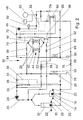
- An internal combustion engine 12 and a transmission 14 of a motor vehicle are connected to a first partial circuit 26 of a cooling and heating circuit 10, in which a coolant pump 24 conveys a coolant (FIG. 1).
- the pump 24 may be driven by a controllable electric motor or mechanically by the internal combustion engine 12 if it has means for adjusting the delivery rate. It promotes the coolant from the internal combustion engine 12 via a first coolant path 32, a bypass line, directly to the internal combustion engine 12 and the transmission 14 back. Only very little heat is removed from the coolant via the bypass line 32, so that the internal combustion engine 12 and the transmission 14 quickly reach an optimum operating temperature. As a result, less fuel is consumed with low pollutant emissions.
- a second coolant path to a radiator 28 is provided, which cooperates with a fan 30 and the coolant extracts excess heat. Moreover, a connection to an expansion tank 78 for the coolant is arranged in the region of the radiator 28.
- a thermostatic valve 34 in the bypass line 32 and a thermostatic valve 36 in the coolant branch to the radiator 28 regulate the coolant flow to the radiator 28 and / or to the bypass line 32.
- the valves 34 and 36 which can also be combined to form a two / three-way valve, receive specifications not shown air conditioning or engine control via a signal line 38th
- An electrically driven engine oil pump 16 and an electrically driven transmission oil pump 18 deliver the engine oil or the transmission oil to an engine oil heat exchanger 40 and a transmission oil heat exchanger 42. They can be operated independently of the internal combustion engine 12 from the electrical system of the motor vehicle.
- the oil inlets of the pumps 16, 18 and the oil heat exchanger 40, 42 are designated 20 and the outlets 22.
- the engine oil heat exchanger 40 and the transmission oil heat exchanger 42 are associated with a second partial circuit 44 of the cooling and heating circuit 10, which primarily takes over the cooling of a fuel cell 50. In the case of a stationary air conditioning, the fuel cell 50 in conjunction with a switching element 48 feeds the electrical system of the motor vehicle.
- thermal energy is generated, which is transported via the coolant of the second partial circuit 44 on a short path to the engine oil heat exchanger 40 and to the transmission oil heat exchanger 42.
- the heat exchangers 40 and 42 then transfer the energy to the engine or transmission oil, so that these media can be heated prior to the start of the engine 12. This facilitates the starting process and quickly brings the units to their optimum operating temperature.
- a heating heat exchanger 54 and a heating fan 56 are arranged in a further branch of the second partial circuit 44.
- the heat input takes place here via the coolant. If the amount of heat emitted by the fuel cell 50 is insufficient, a heater 52 can be temporarily switched on by a switching element 48. On the other hand, if the heat input into the subcircuit 44 exceeds the demand, the excess heat can be discharged via an auxiliary cooler 58 with an auxiliary fan 60 to the environment.
- the second subcircuit 44 can thus operate largely independently in the standby mode of the internal combustion engine 10.
- a reservoir 80 is also provided to compensate for temperature-induced changes in volume of the coolant.
- the coolant is conveyed in the subcircuit 44 independently of the internal combustion engine 12 by means of an electrically driven auxiliary pump 46, wherein the valves 70, 72 and 74 regulate the coolant flows in the individual branches.
- the control is always based on a priority demand, which are transmitted via specifications of a climate or engine control via a signal line 82 to the heating valve 74 and the thermostatic valves 70 and 72.
- a supply line 62 with a flow valve 66 and a return line 64 with a return valve 68 connect the first partial circuit 26 to the second partial circuit 44.
- coolant of the first partial circuit 26 to the engine oil heat exchanger 40 and the transmission oil heat exchanger 42 arrive to ensure the necessary cooling power alone through the radiator 28 or to keep the fuel cell 50 at operating temperature or preheat the internal combustion engine 12 and the transmission 14 through the fuel cell 50 in standby mode via the coolant.
- the coolant volume flow through the flow valve 66 and the return valve 68 is adjusted as needed.
- deionized water which is currently preferred as a fuel cell coolant because of its non-conductive property, is the cooling system 88 of the fuel cell 50 in the second subcircuit 44 formed as a closed system. It has in this embodiment, in addition to the fuel cell 50 and the auxiliary pump 26 special intermediate heat exchanger 84, 86, which provide for the decoupling of the different cooling media and must be performed in stainless steel due to the material compatibility with deionized water (Fig. 2).
- the engine oil heat exchanger 40, the transmission oil heat exchanger 42, and the heater core 54 may be made of conventional materials.
- the special intermediate heat exchangers 84, 86 made of stainless steel can be arbitrarily arranged in the engine compartment and linked to different media streams to be preheated.
- the intermediate heat exchanger 86 is thermally coupled to the engine oil heat exchanger 40 and the transmission oil heat exchanger 42 to allow in this embodiment, the preheating of the engine or transmission oil by utilizing the heat generated during the cooling process of the fuel cell 50 waste heat.
- the heating of the vehicle interior before starting the internal combustion engine 12 is also possible by the heater core 54 is coupled to the intermediate heat exchanger 84, wherein a control valve 76 controls the flow rate and thus determines the heat input.
Abstract
Claims (9)
- Véhicule automobile équipé d'un moteur à combustion interne (12) et d'une installation d'alimentation en énergie auxiliaire, comprenant une pile à combustible (50),
les flux d'énergie et/ou de matière du moteur à combustion interne (12) et de la pile à combustible (50) étant couplés par un circuit de refroidissement et de chauffage (10), selon lequel
le circuit de refroidissement et de chauffage (10) comprennent un premier circuit partiel (26) et un second circuit partiel (44),
le premier circuit (26) est associé au moteur à combustion interne (12) et le second circuit (44) est associé à la pile à combustible (50) et
les deux circuits partiels (26, 44) sont reliés par une conduite d'aller (62) à une vanne d'aller (66) et par une conduite de retour (64) à une vanne de retour (68),
caractérisé en ce que
le second circuit partiel (44) comporte un échangeur de chaleur d'huile de moteur (40) pour le moteur à combustion interne (12) et/ou un échangeur de chaleur d'huile de boîte de vitesses (42). - Véhicule automobile selon la revendication 1,
caractérisé par
une pompe électrique d'huile moteur (16) qui débite l'huile du moteur vers l'échangeur de chaleur d'huile de moteur (40). - Véhicule automobile selon la revendication 1,
caractérisé par
une pompe électrique d'huile de boîte de vitesses (18) qui débite l'huile de la boîte de vitesses (14) vers l'échangeur de chaleur d'huile de boîte de vitesses (42). - Véhicule automobile selon la revendication 3,
caractérisé en ce que
l'échangeur de chaleur d'huile de moteur (40) et l'échangeur de chaleur d'huile de boîte de vitesses (42) sont branchés en parallèle. - Véhicule automobile selon l'une des revendications précédentes,
caractérisé en ce que
le second circuit partiel (44) comporte une pompe électrique complémentaire (46) qui débite l'agent de refroidissement dans le second circuit partiel (44). - Véhicule automobile selon la revendication 5,
caractérisé par
un échangeur de chaleur de chauffage (54) installé dans le second circuit partiel (44) et dont le débit est réglé par une vanne de chauffage (74) à commande électrique. - Véhicule automobile selon l'une des revendications précédentes,
caractérisé par
un dispositif de chauffage supplémentaire (52) relié au second circuit partiel (44). - Véhicule automobile selon l'une des revendications précédentes,
caractérisé en ce que
le second circuit partiel (44) comprend un circuit de refroidissement fermé (88) fonctionnant avec un milieu de refroidissement désionisé et auquel sont raccordés la pile à combustible (50) et/ou le dispositif de chauffage supplémentaire (52) et qui comporte la pompe complémentaire (46),
le dispositif de refroidissement (88), fermé, étant couplé par un échangeur de chaleur intermédiaire (84) au circuit de fluide de refroidissement de l'échangeur de chaleur d'huile moteur (40) et/ou l'échangeur de chaleur d'huile de boite de vitesses (42). - Véhicule automobile selon la revendication 8,
caractérisé en ce que
l'échangeur de chaleur de chauffage (54) est associé au premier circuit partiel (26) et son circuit d'agent de refroidissement est couplé par un second échangeur intermédiaire (86) au circuit de refroidissement fermé (88) du second circuit partiel (44).
Applications Claiming Priority (3)
| Application Number | Priority Date | Filing Date | Title |
|---|---|---|---|
| DE10301609 | 2003-01-17 | ||
| DE10301609A DE10301609A1 (de) | 2003-01-17 | 2003-01-17 | Kraftfahrzeug mit einer Brennkraftmaschine und einer Hilfsenergieversorgungseinrichtung |
| PCT/DE2003/003204 WO2004069572A1 (fr) | 2003-01-17 | 2003-09-25 | Vehicule automobile equipe d'un moteur a combustion interne et d'un dispositif d'alimentation en energie auxiliaire |
Publications (2)
| Publication Number | Publication Date |
|---|---|
| EP1587702A1 EP1587702A1 (fr) | 2005-10-26 |
| EP1587702B1 true EP1587702B1 (fr) | 2007-09-19 |
Family
ID=32602649
Family Applications (1)
| Application Number | Title | Priority Date | Filing Date |
|---|---|---|---|
| EP03769213A Expired - Lifetime EP1587702B1 (fr) | 2003-01-17 | 2003-09-25 | Vehicule automobile equipe d'un moteur a combustion interne et d'un dispositif d'alimentation en energie auxiliaire |
Country Status (5)
| Country | Link |
|---|---|
| US (1) | US20060112695A1 (fr) |
| EP (1) | EP1587702B1 (fr) |
| JP (1) | JP2006513688A (fr) |
| DE (2) | DE10301609A1 (fr) |
| WO (1) | WO2004069572A1 (fr) |
Families Citing this family (20)
| Publication number | Priority date | Publication date | Assignee | Title |
|---|---|---|---|---|
| DE102004061424A1 (de) * | 2004-12-21 | 2006-06-29 | Daimlerchrysler Ag | Kühleinrichtung in einem Brennstoffzellen-Fahrzeug |
| DE102005013598A1 (de) * | 2005-03-24 | 2006-11-16 | Zf Friedrichshafen Ag | Verfahren zum Betreiben eines Antriebsstrangs eines Kraftfahrzeugs |
| JP2007280927A (ja) | 2005-12-12 | 2007-10-25 | Toyota Motor Corp | 燃料電池の冷却システム |
| DE102006049148A1 (de) * | 2006-10-18 | 2008-04-30 | Beru Ag | Verfahren zum Betreiben eines elektrischen Zuheizers in einem Kraftfahrzeug |
| DE102006054670A1 (de) * | 2006-11-17 | 2008-05-21 | J. Eberspächer GmbH & Co. KG | Brennkraftmaschinensystem |
| DE102007006963A1 (de) | 2007-02-13 | 2008-08-14 | Daimler Ag | Brennstoffzellensystem für ein Fahrzeug |
| WO2009061292A1 (fr) * | 2007-11-06 | 2009-05-14 | Carrier Corporation | Pompe à chaleur à récupération de chaleur |
| DE102008027292A1 (de) * | 2008-06-06 | 2009-12-10 | J. Eberspächer GmbH & Co. KG | Brennstoffzellensystem und damit ausgestattetes Kraftfahrzeug |
| US9187083B2 (en) | 2009-09-16 | 2015-11-17 | Polaris Industries Inc. | System and method for charging an on-board battery of an electric vehicle |
| EP2308708B1 (fr) * | 2009-09-16 | 2016-08-17 | swissauto powersport llc | Véhicule électrique doté d'un allongement du rayon d'action |
| JP2017530297A (ja) * | 2014-09-29 | 2017-10-12 | シェフラー テクノロジーズ アー・ゲー ウント コー. カー・ゲーSchaeffler Technologies AG & Co. KG | 軸駆動式エンジン補機 |
| US10300786B2 (en) | 2014-12-19 | 2019-05-28 | Polaris Industries Inc. | Utility vehicle |
| US20170241308A1 (en) * | 2016-02-24 | 2017-08-24 | Ford Global Technologies, Llc | Oil maintenance strategy for electrified vehicles |
| IL296644B2 (en) | 2016-06-14 | 2023-12-01 | Polaris Inc | Hybrid vehicle |
| GB2552199B (en) * | 2016-07-13 | 2020-08-19 | Arrival Ltd | Thermal management in a vehicle |
| DE102016115626A1 (de) | 2016-08-23 | 2018-04-05 | Audi Ag | Standklimatisiereinrichtung sowie Verfahren zum Standklimatisieren einer Fahrgastzelle |
| US10844760B2 (en) * | 2018-01-30 | 2020-11-24 | Cumming Power Generation IP, Inc. | Oil heater for a generator set |
| US10780770B2 (en) | 2018-10-05 | 2020-09-22 | Polaris Industries Inc. | Hybrid utility vehicle |
| EP3640069B1 (fr) * | 2018-10-16 | 2021-05-05 | Magna Energy Storage Systems GesmbH | Véhicule automobile pourvu de récipient à liquide |
| US11370266B2 (en) | 2019-05-16 | 2022-06-28 | Polaris Industries Inc. | Hybrid utility vehicle |
Family Cites Families (3)
| Publication number | Priority date | Publication date | Assignee | Title |
|---|---|---|---|---|
| DE19961825A1 (de) * | 1999-12-21 | 2001-06-28 | Valeo Klimasysteme Gmbh | Kühl-Heiz-Kreis mit zwei Kühlern |
| DE10142923A1 (de) * | 2000-09-21 | 2002-04-18 | Daimler Chrysler Ag | Hybridantriebsvorrichtung und Verfahren zum Betreiben der Hybridantriebsvorrichtung |
| US6463889B2 (en) * | 2001-03-08 | 2002-10-15 | General Motors Corporation | POx cold start vapor system |
-
2003
- 2003-01-17 DE DE10301609A patent/DE10301609A1/de not_active Withdrawn
- 2003-09-25 DE DE50308251T patent/DE50308251D1/de not_active Expired - Fee Related
- 2003-09-25 US US10/541,831 patent/US20060112695A1/en not_active Abandoned
- 2003-09-25 JP JP2004567701A patent/JP2006513688A/ja not_active Withdrawn
- 2003-09-25 EP EP03769213A patent/EP1587702B1/fr not_active Expired - Lifetime
- 2003-09-25 WO PCT/DE2003/003204 patent/WO2004069572A1/fr active IP Right Grant
Also Published As
| Publication number | Publication date |
|---|---|
| DE10301609A1 (de) | 2004-07-29 |
| WO2004069572A1 (fr) | 2004-08-19 |
| DE50308251D1 (de) | 2007-10-31 |
| JP2006513688A (ja) | 2006-04-20 |
| EP1587702A1 (fr) | 2005-10-26 |
| US20060112695A1 (en) | 2006-06-01 |
Similar Documents
| Publication | Publication Date | Title |
|---|---|---|
| EP1587702B1 (fr) | Vehicule automobile equipe d'un moteur a combustion interne et d'un dispositif d'alimentation en energie auxiliaire | |
| WO2015091969A1 (fr) | Gestion thermique pour un véhicule électrique ou hybride ainsi que procédé pour le conditionnement de l'habitacle d'un tel véhicule automobile | |
| DE10161851A1 (de) | Kühlkreislauf einer flüssigkeitsgekühlten Brennkraftmaschine | |
| EP2517298B1 (fr) | Procédé destiné à tempérer une source de courant d'un véhicule | |
| DE102009059237B4 (de) | Fahrzeugheizkreislauf | |
| WO2011036239A1 (fr) | Système pour un véhicule automobile pour réchauffer et/ou refroidir une batterie et un habitacle de véhicule | |
| WO2011076199A1 (fr) | Système de refroidissement de véhicule à moteur | |
| DE19960960C1 (de) | Wärmeaustauschsystem für die Heizung eines Fahrzeugs mit Hybridantrieb | |
| DE102009043316A1 (de) | Verfahren zur Steuerung der Innenraumtemperatur eines elektrisch betriebenen Fahrzeugs und Klimaanlagensystem | |
| EP3747074B1 (fr) | Système de refroidissement conçu pour un empilement de pile à combustible | |
| DE102011118898A1 (de) | Vorrichtung und Verfahren zur thermischen Kopplung zweier Kühlkreisläufe in einem Fahrzeug | |
| EP1561617B1 (fr) | Système pour tempérer un véhicule | |
| DE10234087A1 (de) | Verfahren zum Betrieb eines Kühl- und Heizkreislaufs eines Kraftfahrzeugs sowie Kühl- und Heizkreislauf für ein Kraftfahrzeug | |
| EP1623101A2 (fr) | Circuit pour refroidir de l'air de suralimentation et procede d'exploitation d'un circuit de ce type | |
| DE102012223136B4 (de) | Verfahren zum Betrieb einer Halbleitervorrichtung und eines Kühlsystem für die Halbleitervorrichtung | |
| EP3785953B1 (fr) | Système de mise en température pour véhicule | |
| DE102009053387B4 (de) | Vorrichtung und Verfahren zum Beheizen eines Fahrgastraums eines elektrisch antreibbaren Fahrzeugs | |
| EP1536961B1 (fr) | Systeme et procede de regulation de l'etat thermique d'un vehicule | |
| EP4171979A1 (fr) | Circuit d'agent caloporteur pour un véhicule automobile | |
| DE10023508B4 (de) | Kühlanlage eines flüssigkeitsgekühlten Verbrennungsmotors | |
| DE102009005638B4 (de) | Fahrzeugtemperiersystem, insbesondere zur thermischen Behandlung der in einen Fahrzeuginnenraum einzuleitenden Luft | |
| DE102018009269B4 (de) | Klimatisierungseinrichtung für ein Kraftfahrzeug, sowie Kraftfahrzeug damit | |
| DE10343775B4 (de) | Leistungsbedarfsgesteuertes Kühl- und Heizsystem für Kraftfahrzeuge mit unabhängig von der Brennkraftmaschine antreibbarer Fördervorrichtung | |
| DE102008013251A1 (de) | Brennkraftmaschinen-Kühlkreislauf | |
| DE19750721A1 (de) | Kühlmittelkreislauf eines Verbrennungsmotors |
Legal Events
| Date | Code | Title | Description |
|---|---|---|---|
| PUAI | Public reference made under article 153(3) epc to a published international application that has entered the european phase |
Free format text: ORIGINAL CODE: 0009012 |
|
| 17P | Request for examination filed |
Effective date: 20050817 |
|
| AK | Designated contracting states |
Kind code of ref document: A1 Designated state(s): AT BE BG CH CY CZ DE DK EE ES FI FR GB GR HU IE IT LI LU MC NL PT RO SE SI SK TR |
|
| RBV | Designated contracting states (corrected) |
Designated state(s): DE FR |
|
| 17Q | First examination report despatched |
Effective date: 20060619 |
|
| GRAP | Despatch of communication of intention to grant a patent |
Free format text: ORIGINAL CODE: EPIDOSNIGR1 |
|
| GRAS | Grant fee paid |
Free format text: ORIGINAL CODE: EPIDOSNIGR3 |
|
| GRAA | (expected) grant |
Free format text: ORIGINAL CODE: 0009210 |
|
| AK | Designated contracting states |
Kind code of ref document: B1 Designated state(s): DE FR |
|
| REF | Corresponds to: |
Ref document number: 50308251 Country of ref document: DE Date of ref document: 20071031 Kind code of ref document: P |
|
| EN | Fr: translation not filed | ||
| PLBE | No opposition filed within time limit |
Free format text: ORIGINAL CODE: 0009261 |
|
| STAA | Information on the status of an ep patent application or granted ep patent |
Free format text: STATUS: NO OPPOSITION FILED WITHIN TIME LIMIT |
|
| PG25 | Lapsed in a contracting state [announced via postgrant information from national office to epo] |
Ref country code: DE Free format text: LAPSE BECAUSE OF NON-PAYMENT OF DUE FEES Effective date: 20080401 |
|
| 26N | No opposition filed |
Effective date: 20080620 |
|
| PG25 | Lapsed in a contracting state [announced via postgrant information from national office to epo] |
Ref country code: FR Free format text: LAPSE BECAUSE OF FAILURE TO SUBMIT A TRANSLATION OF THE DESCRIPTION OR TO PAY THE FEE WITHIN THE PRESCRIBED TIME-LIMIT Effective date: 20080523 |