EP1587702B1 - Kraftfahrzeug mit einer brennkraftmaschine und einer hilfsenergieversorgungseinrichtung - Google Patents
Kraftfahrzeug mit einer brennkraftmaschine und einer hilfsenergieversorgungseinrichtung Download PDFInfo
- Publication number
- EP1587702B1 EP1587702B1 EP03769213A EP03769213A EP1587702B1 EP 1587702 B1 EP1587702 B1 EP 1587702B1 EP 03769213 A EP03769213 A EP 03769213A EP 03769213 A EP03769213 A EP 03769213A EP 1587702 B1 EP1587702 B1 EP 1587702B1
- Authority
- EP
- European Patent Office
- Prior art keywords
- heat exchanger
- internal combustion
- combustion engine
- motor vehicle
- fuel cell
- Prior art date
- Legal status (The legal status is an assumption and is not a legal conclusion. Google has not performed a legal analysis and makes no representation as to the accuracy of the status listed.)
- Expired - Lifetime
Links
- 238000002485 combustion reaction Methods 0.000 title claims abstract description 48
- 239000000446 fuel Substances 0.000 claims abstract description 49
- 238000001816 cooling Methods 0.000 claims abstract description 30
- 238000010438 heat treatment Methods 0.000 claims abstract description 27
- 239000000463 material Substances 0.000 claims abstract description 7
- 239000002826 coolant Substances 0.000 claims description 35
- 239000003921 oil Substances 0.000 claims description 27
- 239000010705 motor oil Substances 0.000 claims description 24
- 239000012208 gear oil Substances 0.000 claims description 7
- 230000001105 regulatory effect Effects 0.000 claims 1
- 230000004907 flux Effects 0.000 abstract 2
- 230000005540 biological transmission Effects 0.000 description 26
- 238000004378 air conditioning Methods 0.000 description 5
- 239000002918 waste heat Substances 0.000 description 5
- 239000008367 deionised water Substances 0.000 description 4
- 229910021641 deionized water Inorganic materials 0.000 description 4
- 229910001220 stainless steel Inorganic materials 0.000 description 4
- 239000010935 stainless steel Substances 0.000 description 4
- XLYOFNOQVPJJNP-UHFFFAOYSA-N water Chemical compound O XLYOFNOQVPJJNP-UHFFFAOYSA-N 0.000 description 4
- 239000003054 catalyst Substances 0.000 description 2
- 239000003344 environmental pollutant Substances 0.000 description 2
- 239000007789 gas Substances 0.000 description 2
- 238000000034 method Methods 0.000 description 2
- 231100000719 pollutant Toxicity 0.000 description 2
- 239000000126 substance Substances 0.000 description 2
- 239000000498 cooling water Substances 0.000 description 1
- 239000000284 extract Substances 0.000 description 1
- 239000010687 lubricating oil Substances 0.000 description 1
- 238000013021 overheating Methods 0.000 description 1
- 238000010257 thawing Methods 0.000 description 1
Images

Classifications
-
- F—MECHANICAL ENGINEERING; LIGHTING; HEATING; WEAPONS; BLASTING
- F01—MACHINES OR ENGINES IN GENERAL; ENGINE PLANTS IN GENERAL; STEAM ENGINES
- F01P—COOLING OF MACHINES OR ENGINES IN GENERAL; COOLING OF INTERNAL-COMBUSTION ENGINES
- F01P7/00—Controlling of coolant flow
- F01P7/14—Controlling of coolant flow the coolant being liquid
- F01P7/16—Controlling of coolant flow the coolant being liquid by thermostatic control
- F01P7/165—Controlling of coolant flow the coolant being liquid by thermostatic control characterised by systems with two or more loops
-
- B—PERFORMING OPERATIONS; TRANSPORTING
- B60—VEHICLES IN GENERAL
- B60K—ARRANGEMENT OR MOUNTING OF PROPULSION UNITS OR OF TRANSMISSIONS IN VEHICLES; ARRANGEMENT OR MOUNTING OF PLURAL DIVERSE PRIME-MOVERS IN VEHICLES; AUXILIARY DRIVES FOR VEHICLES; INSTRUMENTATION OR DASHBOARDS FOR VEHICLES; ARRANGEMENTS IN CONNECTION WITH COOLING, AIR INTAKE, GAS EXHAUST OR FUEL SUPPLY OF PROPULSION UNITS IN VEHICLES
- B60K6/00—Arrangement or mounting of plural diverse prime-movers for mutual or common propulsion, e.g. hybrid propulsion systems comprising electric motors and internal combustion engines ; Control systems therefor, i.e. systems controlling two or more prime movers, or controlling one of these prime movers and any of the transmission, drive or drive units Informative references: mechanical gearings with secondary electric drive F16H3/72; arrangements for handling mechanical energy structurally associated with the dynamo-electric machine H02K7/00; machines comprising structurally interrelated motor and generator parts H02K51/00; dynamo-electric machines not otherwise provided for in H02K see H02K99/00
- B60K6/20—Arrangement or mounting of plural diverse prime-movers for mutual or common propulsion, e.g. hybrid propulsion systems comprising electric motors and internal combustion engines ; Control systems therefor, i.e. systems controlling two or more prime movers, or controlling one of these prime movers and any of the transmission, drive or drive units Informative references: mechanical gearings with secondary electric drive F16H3/72; arrangements for handling mechanical energy structurally associated with the dynamo-electric machine H02K7/00; machines comprising structurally interrelated motor and generator parts H02K51/00; dynamo-electric machines not otherwise provided for in H02K see H02K99/00 the prime-movers consisting of electric motors and internal combustion engines, e.g. HEVs
- B60K6/22—Arrangement or mounting of plural diverse prime-movers for mutual or common propulsion, e.g. hybrid propulsion systems comprising electric motors and internal combustion engines ; Control systems therefor, i.e. systems controlling two or more prime movers, or controlling one of these prime movers and any of the transmission, drive or drive units Informative references: mechanical gearings with secondary electric drive F16H3/72; arrangements for handling mechanical energy structurally associated with the dynamo-electric machine H02K7/00; machines comprising structurally interrelated motor and generator parts H02K51/00; dynamo-electric machines not otherwise provided for in H02K see H02K99/00 the prime-movers consisting of electric motors and internal combustion engines, e.g. HEVs characterised by apparatus, components or means specially adapted for HEVs
- B60K6/32—Arrangement or mounting of plural diverse prime-movers for mutual or common propulsion, e.g. hybrid propulsion systems comprising electric motors and internal combustion engines ; Control systems therefor, i.e. systems controlling two or more prime movers, or controlling one of these prime movers and any of the transmission, drive or drive units Informative references: mechanical gearings with secondary electric drive F16H3/72; arrangements for handling mechanical energy structurally associated with the dynamo-electric machine H02K7/00; machines comprising structurally interrelated motor and generator parts H02K51/00; dynamo-electric machines not otherwise provided for in H02K see H02K99/00 the prime-movers consisting of electric motors and internal combustion engines, e.g. HEVs characterised by apparatus, components or means specially adapted for HEVs characterised by the fuel cells
-
- F—MECHANICAL ENGINEERING; LIGHTING; HEATING; WEAPONS; BLASTING
- F01—MACHINES OR ENGINES IN GENERAL; ENGINE PLANTS IN GENERAL; STEAM ENGINES
- F01M—LUBRICATING OF MACHINES OR ENGINES IN GENERAL; LUBRICATING INTERNAL COMBUSTION ENGINES; CRANKCASE VENTILATING
- F01M5/00—Heating, cooling, or controlling temperature of lubricant; Lubrication means facilitating engine starting
- F01M5/02—Conditioning lubricant for aiding engine starting, e.g. heating
- F01M5/021—Conditioning lubricant for aiding engine starting, e.g. heating by heating
-
- F—MECHANICAL ENGINEERING; LIGHTING; HEATING; WEAPONS; BLASTING
- F01—MACHINES OR ENGINES IN GENERAL; ENGINE PLANTS IN GENERAL; STEAM ENGINES
- F01P—COOLING OF MACHINES OR ENGINES IN GENERAL; COOLING OF INTERNAL-COMBUSTION ENGINES
- F01P3/00—Liquid cooling
- F01P3/20—Cooling circuits not specific to a single part of engine or machine
-
- H—ELECTRICITY
- H01—ELECTRIC ELEMENTS
- H01M—PROCESSES OR MEANS, e.g. BATTERIES, FOR THE DIRECT CONVERSION OF CHEMICAL ENERGY INTO ELECTRICAL ENERGY
- H01M8/00—Fuel cells; Manufacture thereof
- H01M8/04—Auxiliary arrangements, e.g. for control of pressure or for circulation of fluids
- H01M8/04007—Auxiliary arrangements, e.g. for control of pressure or for circulation of fluids related to heat exchange
- H01M8/04029—Heat exchange using liquids
-
- F—MECHANICAL ENGINEERING; LIGHTING; HEATING; WEAPONS; BLASTING
- F01—MACHINES OR ENGINES IN GENERAL; ENGINE PLANTS IN GENERAL; STEAM ENGINES
- F01P—COOLING OF MACHINES OR ENGINES IN GENERAL; COOLING OF INTERNAL-COMBUSTION ENGINES
- F01P3/00—Liquid cooling
- F01P2003/001—Cooling liquid
-
- F—MECHANICAL ENGINEERING; LIGHTING; HEATING; WEAPONS; BLASTING
- F01—MACHINES OR ENGINES IN GENERAL; ENGINE PLANTS IN GENERAL; STEAM ENGINES
- F01P—COOLING OF MACHINES OR ENGINES IN GENERAL; COOLING OF INTERNAL-COMBUSTION ENGINES
- F01P5/00—Pumping cooling-air or liquid coolants
- F01P5/10—Pumping liquid coolant; Arrangements of coolant pumps
- F01P2005/105—Using two or more pumps
-
- F—MECHANICAL ENGINEERING; LIGHTING; HEATING; WEAPONS; BLASTING
- F01—MACHINES OR ENGINES IN GENERAL; ENGINE PLANTS IN GENERAL; STEAM ENGINES
- F01P—COOLING OF MACHINES OR ENGINES IN GENERAL; COOLING OF INTERNAL-COMBUSTION ENGINES
- F01P5/00—Pumping cooling-air or liquid coolants
- F01P5/10—Pumping liquid coolant; Arrangements of coolant pumps
- F01P5/12—Pump-driving arrangements
- F01P2005/125—Driving auxiliary pumps electrically
-
- F—MECHANICAL ENGINEERING; LIGHTING; HEATING; WEAPONS; BLASTING
- F01—MACHINES OR ENGINES IN GENERAL; ENGINE PLANTS IN GENERAL; STEAM ENGINES
- F01P—COOLING OF MACHINES OR ENGINES IN GENERAL; COOLING OF INTERNAL-COMBUSTION ENGINES
- F01P7/00—Controlling of coolant flow
- F01P7/14—Controlling of coolant flow the coolant being liquid
- F01P2007/146—Controlling of coolant flow the coolant being liquid using valves
-
- F—MECHANICAL ENGINEERING; LIGHTING; HEATING; WEAPONS; BLASTING
- F01—MACHINES OR ENGINES IN GENERAL; ENGINE PLANTS IN GENERAL; STEAM ENGINES
- F01P—COOLING OF MACHINES OR ENGINES IN GENERAL; COOLING OF INTERNAL-COMBUSTION ENGINES
- F01P2050/00—Applications
- F01P2050/24—Hybrid vehicles
-
- F—MECHANICAL ENGINEERING; LIGHTING; HEATING; WEAPONS; BLASTING
- F01—MACHINES OR ENGINES IN GENERAL; ENGINE PLANTS IN GENERAL; STEAM ENGINES
- F01P—COOLING OF MACHINES OR ENGINES IN GENERAL; COOLING OF INTERNAL-COMBUSTION ENGINES
- F01P2060/00—Cooling circuits using auxiliaries
- F01P2060/04—Lubricant cooler
- F01P2060/045—Lubricant cooler for transmissions
-
- F—MECHANICAL ENGINEERING; LIGHTING; HEATING; WEAPONS; BLASTING
- F01—MACHINES OR ENGINES IN GENERAL; ENGINE PLANTS IN GENERAL; STEAM ENGINES
- F01P—COOLING OF MACHINES OR ENGINES IN GENERAL; COOLING OF INTERNAL-COMBUSTION ENGINES
- F01P7/00—Controlling of coolant flow
- F01P7/14—Controlling of coolant flow the coolant being liquid
- F01P7/16—Controlling of coolant flow the coolant being liquid by thermostatic control
- F01P7/164—Controlling of coolant flow the coolant being liquid by thermostatic control by varying pump speed
-
- H—ELECTRICITY
- H01—ELECTRIC ELEMENTS
- H01M—PROCESSES OR MEANS, e.g. BATTERIES, FOR THE DIRECT CONVERSION OF CHEMICAL ENERGY INTO ELECTRICAL ENERGY
- H01M2250/00—Fuel cells for particular applications; Specific features of fuel cell system
- H01M2250/20—Fuel cells in motive systems, e.g. vehicle, ship, plane
-
- H—ELECTRICITY
- H01—ELECTRIC ELEMENTS
- H01M—PROCESSES OR MEANS, e.g. BATTERIES, FOR THE DIRECT CONVERSION OF CHEMICAL ENERGY INTO ELECTRICAL ENERGY
- H01M2250/00—Fuel cells for particular applications; Specific features of fuel cell system
- H01M2250/40—Combination of fuel cells with other energy production systems
- H01M2250/407—Combination of fuel cells with mechanical energy generators
-
- Y—GENERAL TAGGING OF NEW TECHNOLOGICAL DEVELOPMENTS; GENERAL TAGGING OF CROSS-SECTIONAL TECHNOLOGIES SPANNING OVER SEVERAL SECTIONS OF THE IPC; TECHNICAL SUBJECTS COVERED BY FORMER USPC CROSS-REFERENCE ART COLLECTIONS [XRACs] AND DIGESTS
- Y02—TECHNOLOGIES OR APPLICATIONS FOR MITIGATION OR ADAPTATION AGAINST CLIMATE CHANGE
- Y02E—REDUCTION OF GREENHOUSE GAS [GHG] EMISSIONS, RELATED TO ENERGY GENERATION, TRANSMISSION OR DISTRIBUTION
- Y02E60/00—Enabling technologies; Technologies with a potential or indirect contribution to GHG emissions mitigation
- Y02E60/30—Hydrogen technology
- Y02E60/50—Fuel cells
-
- Y—GENERAL TAGGING OF NEW TECHNOLOGICAL DEVELOPMENTS; GENERAL TAGGING OF CROSS-SECTIONAL TECHNOLOGIES SPANNING OVER SEVERAL SECTIONS OF THE IPC; TECHNICAL SUBJECTS COVERED BY FORMER USPC CROSS-REFERENCE ART COLLECTIONS [XRACs] AND DIGESTS
- Y02—TECHNOLOGIES OR APPLICATIONS FOR MITIGATION OR ADAPTATION AGAINST CLIMATE CHANGE
- Y02T—CLIMATE CHANGE MITIGATION TECHNOLOGIES RELATED TO TRANSPORTATION
- Y02T90/00—Enabling technologies or technologies with a potential or indirect contribution to GHG emissions mitigation
- Y02T90/40—Application of hydrogen technology to transportation, e.g. using fuel cells
Definitions
- the invention is based on a motor vehicle with an internal combustion engine and an auxiliary energy supply device according to the preamble of claim 1.
- a heat input into the cooling water by the engine itself is not given or sufficient, especially if the efficiency of the engine is very good and consequently low heat losses.
- the internal combustion engine does not reach its optimum temperature in the short time, or only very late, resulting in increased fuel consumption and increased exhaust emissions.
- From the EP 1 203 697 A2 is a motor vehicle with an internal combustion engine and an auxiliary power supply device, even APU (A uxiliary P ower U nit) mentioned known for electrical consumers on board the motor vehicle, comprising a fuel cell system and a battery coupled thereto.
- APU A uxiliary P ower U nit
- the internal combustion engine and the fuel cell system are connected to a common cooling and heating circuit in which a radiator simultaneously cools the internal combustion engine and the fuel cell system. This is favored by different peak cooling powers, which are required for the internal combustion engine during driving and for the fuel cell system during vehicle standstill, for example in the starting phase or when operating a parking heater.
- the exhaust gas of the internal combustion engine is passed through a system comprising a heat exchanger and / or an exhaust gas catalyst.
- This system is thermally coupled to the fuel cell system. It is thus possible by means of the exhaust heat of the internal combustion engine to preheat the fuel cell system.
- the fuel cell system is maintained at operating temperature and is thus available at an increased energy demand in a short time.
- the fuel cell system is thermally connected to an air conditioner and / or a heater, so that their waste heat can be used if necessary for heating the passenger compartment.
- a hybrid drive device for vehicles which comprises at least one fuel cell, an internal combustion engine, a generator and / or an electric motor and a common cooling device for the fuel cell and the internal combustion engine.
- the internal combustion engine, the fuel cell and the cooling device are thermally conductively connected to each other by heat conduction.
- control means are provided, via which a control of a heat flow of heat of the internal combustion engine to the cooling device and / or the fuel cell, heat of the fuel cell to the cooling device and / or the internal combustion engine, and / or heat of the cooling device to the internal combustion engine and / or the fuel cell takes place.
- a cooling and heating circuit has a first and a second partial circuit, of which the first of the internal combustion engine and the second of the fuel cell is assigned.
- the two partial circuits are connected to each other, through a supply line with a flow valve and through a return line with a return valve.
- an engine oil heat exchanger and / or a gear oil heat exchanger are arranged in addition to the fuel cell, wherein a further valve of the second subcircuit to the engine oil heat exchanger for the engine oil of the engine and the gear oil heat exchanger is opened by means of a controllable valve, so that these media on the coolant of this subcircuit be heated specifically.
- the control of the heat flows oriented in each case after a priority requirement and can be done both by a climate control unit or by a timing of a motor control. It is known that early heating of the engine or transmission oil reduces fuel consumption. In addition to saving fuel, the early heating of the engine or transmission oil shortens the starting time of the internal combustion engine and increases its service life, since lower temperature fluctuations occur in the starting phase.
- the second partial circuit Before the start of the internal combustion engine at low outside temperatures, the second partial circuit takes over the cooling of the fuel cell. Due to a variety of supplying electrical consumers in the Standby mode of the motor vehicle, the fuel cell is exposed to peak load in this operating state, so that relatively much waste heat is produced during operation of the fuel cell. This waste heat is transported via the coolant of the second partial circuit on a short path to an aggregate with heat demand, for example, the heating heat exchanger of the air conditioning.
- the engine oil heat exchanger and / or the Getriebeölmaschinerem (2004) be selectively heated with the coolant of the second partial circuit as soon as a desired temperature of the vehicle interior is reached or when the internal combustion engine is to be started.
- a heater can also be arranged expediently in the second partial circuit, which emits additional heat to the coolant if necessary.
- the different, namely lower, temperature level of the fuel cell relative to the internal combustion engine can furthermore advantageously be taken into account, whereby damage to the fuel cell due to overheating is avoided.
- the engine oil heat exchanger and the transmission oil heat exchanger are connected in parallel and integrated into the second subcircuit, wherein the flow line and return line, which connect the first subcircuit with the second subcircuit, are connected before and after the oil coolers to the second subcircuit.
- the inflow and outflow of the coolant in this cooling branch is also adjusted according to requirements of the air conditioning and / or engine control as needed by control valves.
- the engine oil heat exchanger and the transmission oil heat exchanger in case of increased cooling power demand, for example, driving, by opening the valves in the flow and return line supplied with coolant of the engine part circuit, while before and at the start of the engine for preheating primarily from the coolant of the fuel cell and / or the auxiliary heater to be flowed through.
- the heat input into the coolant is either transported to demand sites or discharged to the environment via a cooler arranged in this partial cycle.
- an electrically driven pump delivers the lubricating oil of the internal combustion engine and the transmission oil to the engine oil heat exchanger and the transmission oil heat exchanger.
- an electrically driven auxiliary pump for conveying the coolant is arranged in the second partial circuit. Since these pumps can be operated in standby mode independently of the internal combustion engine via the electrical system of the motor vehicle, their use advantageously before starting the preheating of both the engine and transmission oil and the internal combustion engine and the transmission itself. Due to the lower viscosity of the heated oil the start of the internal combustion engine improved, especially at low ambient temperatures, even if the temperature of the internal combustion engine has been increased only slightly. In order to heat the vehicle interior at the same time, the coolant flow of the heating heat exchanger is controlled by an electrically controllable heating valve.
- the cooling system of the fuel cell in the second partial circuit is designed as a closed system.
- the engine oil heat exchanger, the transmission oil heat exchanger and the heater core may be made of conventional materials.
- the special intermediate heat exchangers made of stainless steel can be arranged arbitrarily in the engine compartment and linked with different media streams to be preheated.
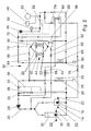
- An internal combustion engine 12 and a transmission 14 of a motor vehicle are connected to a first partial circuit 26 of a cooling and heating circuit 10, in which a coolant pump 24 conveys a coolant (FIG. 1).
- the pump 24 may be driven by a controllable electric motor or mechanically by the internal combustion engine 12 if it has means for adjusting the delivery rate. It promotes the coolant from the internal combustion engine 12 via a first coolant path 32, a bypass line, directly to the internal combustion engine 12 and the transmission 14 back. Only very little heat is removed from the coolant via the bypass line 32, so that the internal combustion engine 12 and the transmission 14 quickly reach an optimum operating temperature. As a result, less fuel is consumed with low pollutant emissions.
- a second coolant path to a radiator 28 is provided, which cooperates with a fan 30 and the coolant extracts excess heat. Moreover, a connection to an expansion tank 78 for the coolant is arranged in the region of the radiator 28.
- a thermostatic valve 34 in the bypass line 32 and a thermostatic valve 36 in the coolant branch to the radiator 28 regulate the coolant flow to the radiator 28 and / or to the bypass line 32.
- the valves 34 and 36 which can also be combined to form a two / three-way valve, receive specifications not shown air conditioning or engine control via a signal line 38th
- An electrically driven engine oil pump 16 and an electrically driven transmission oil pump 18 deliver the engine oil or the transmission oil to an engine oil heat exchanger 40 and a transmission oil heat exchanger 42. They can be operated independently of the internal combustion engine 12 from the electrical system of the motor vehicle.
- the oil inlets of the pumps 16, 18 and the oil heat exchanger 40, 42 are designated 20 and the outlets 22.
- the engine oil heat exchanger 40 and the transmission oil heat exchanger 42 are associated with a second partial circuit 44 of the cooling and heating circuit 10, which primarily takes over the cooling of a fuel cell 50. In the case of a stationary air conditioning, the fuel cell 50 in conjunction with a switching element 48 feeds the electrical system of the motor vehicle.
- thermal energy is generated, which is transported via the coolant of the second partial circuit 44 on a short path to the engine oil heat exchanger 40 and to the transmission oil heat exchanger 42.
- the heat exchangers 40 and 42 then transfer the energy to the engine or transmission oil, so that these media can be heated prior to the start of the engine 12. This facilitates the starting process and quickly brings the units to their optimum operating temperature.
- a heating heat exchanger 54 and a heating fan 56 are arranged in a further branch of the second partial circuit 44.
- the heat input takes place here via the coolant. If the amount of heat emitted by the fuel cell 50 is insufficient, a heater 52 can be temporarily switched on by a switching element 48. On the other hand, if the heat input into the subcircuit 44 exceeds the demand, the excess heat can be discharged via an auxiliary cooler 58 with an auxiliary fan 60 to the environment.
- the second subcircuit 44 can thus operate largely independently in the standby mode of the internal combustion engine 10.
- a reservoir 80 is also provided to compensate for temperature-induced changes in volume of the coolant.
- the coolant is conveyed in the subcircuit 44 independently of the internal combustion engine 12 by means of an electrically driven auxiliary pump 46, wherein the valves 70, 72 and 74 regulate the coolant flows in the individual branches.
- the control is always based on a priority demand, which are transmitted via specifications of a climate or engine control via a signal line 82 to the heating valve 74 and the thermostatic valves 70 and 72.
- a supply line 62 with a flow valve 66 and a return line 64 with a return valve 68 connect the first partial circuit 26 to the second partial circuit 44.
- coolant of the first partial circuit 26 to the engine oil heat exchanger 40 and the transmission oil heat exchanger 42 arrive to ensure the necessary cooling power alone through the radiator 28 or to keep the fuel cell 50 at operating temperature or preheat the internal combustion engine 12 and the transmission 14 through the fuel cell 50 in standby mode via the coolant.
- the coolant volume flow through the flow valve 66 and the return valve 68 is adjusted as needed.
- deionized water which is currently preferred as a fuel cell coolant because of its non-conductive property, is the cooling system 88 of the fuel cell 50 in the second subcircuit 44 formed as a closed system. It has in this embodiment, in addition to the fuel cell 50 and the auxiliary pump 26 special intermediate heat exchanger 84, 86, which provide for the decoupling of the different cooling media and must be performed in stainless steel due to the material compatibility with deionized water (Fig. 2).
- the engine oil heat exchanger 40, the transmission oil heat exchanger 42, and the heater core 54 may be made of conventional materials.
- the special intermediate heat exchangers 84, 86 made of stainless steel can be arbitrarily arranged in the engine compartment and linked to different media streams to be preheated.
- the intermediate heat exchanger 86 is thermally coupled to the engine oil heat exchanger 40 and the transmission oil heat exchanger 42 to allow in this embodiment, the preheating of the engine or transmission oil by utilizing the heat generated during the cooling process of the fuel cell 50 waste heat.
- the heating of the vehicle interior before starting the internal combustion engine 12 is also possible by the heater core 54 is coupled to the intermediate heat exchanger 84, wherein a control valve 76 controls the flow rate and thus determines the heat input.
Abstract
Description
- Die Erfindung geht von einem Kraftfahrzeug mit einer Brennkraftmaschine und einer Hilfsenergieversorgungseinrichtung nach dem Oberbegriff des Anspruchs 1 aus.
- In einigen Betriebszuständen des Kraftfahrzeugs, beispielsweise vor oder beim Kaltstart, beim Kurzstreckenverkehr oder bei langen Talfahrten, ist ein Wärmeeintrag ins Kühlwasser durch die Brennkraftmaschine selbst nicht gegeben oder nicht ausreichend, insbesondere wenn der Wirkungsgrad der Brennkraftmaschine sehr gut ist und folglich geringe Wärmeverluste entstehen. Demzufolge erreicht die Brennkraftmaschine ihre optimale Temperatur in der kurzen Zeit nicht oder erst sehr spät, was zu einem erhöhten Kraftstoff verbrauch und zu erhöhten Abgasemissionen führt.
- Zudem werden bei niedrigen Außentemperaturen erhebliche Wärmemengen benötigt, um die Fahrzeugscheiben zu enteisen oder den Fahrzeuginnenraum zu beheizen und so eine ausreichende Fahrsicherheit und einen guten Fahrkomfort sicherzustellen. Derzeit wird diese Problematik vorwiegend mit chemischen oder elektrischen Zuheizem gelöst. Chemische Zuheizer, beispielsweise Brenner, bieten zwar durch die Möglichkeit, auch im Stillstand der Brennkraftmaschine zu heizen, einen hohen Komfort, sind aber relativ teuer. Elektrische Zuheizer nach dem Prinzip einer Widerstandsheizung sind in der Leistung eingeschränkt, weil durch den Generator und die Batterie nicht beliebig viel Strom zur Verfügung gestellt werden kann.
- Aus der
EP 1 203 697 A2 ist ein Kraftfahrzeug mit einer Brennkraftmaschine und einer Hilfsenergieversorgungseinrichtung, auch APU (Auxiliary Power Unit) genannt, für elektrische Verbraucher an Bord des Kraftfahrzeugs bekannt, die ein Brennstoffzellensystem und eine damit gekoppelte Batterie umfasst. Durch diese Einrichtung wird die elektrische Leistung des Kraftfahrzeugs erhöht und die Möglichkeit geschaffen, eine größere Anzahl elektrischer Verbraucher unabhängig vom Betrieb der Brennkraftmaschine zu betreiben. Die Brennkraftmaschine und das Brennstoffzellensystem sind an einen gemeinsamen Kühl- und Heizkreislauf angeschlossen, in dem ein Kühler gleichzeitig die Brennkraftmaschine und das Brennstoffzellensystem kühlt. Das wird begünstigt durch unterschiedliche Spitzenkühlleistungen, die für die Brennkraftmaschine beim Fahrbetrieb und für das Brennstoffzellensystem beim Fahrzeugstillstand erforderlich sind, beispielsweise in der Startphase oder beim Betrieb einer Standheizung. - Sinnvollerweise werden dabei entstehende Energie- und/oder Stoffströme miteinander gekoppelt, indem z.B. das Abgas der Brennkraftmaschine durch ein System geleitet wird, das einen Wärmetauscher und/oder einen Abgaskatalysator umfasst. Dieses System ist mit dem Brennstoffzellensystem thermisch gekoppelt. Es ist somit möglich mittels der Abgaswärme der Brennkraftmaschine das Brennstoffzellensystem vorzuheizen. Während des Betriebs der Brennkraftmaschine wird das Brennstoffzellensystem auf Betriebstemperatur gehalten und steht so bei einem erhöhten Energiebedarf in kurzer Zeit zur Verfügung. Andererseits kann mit der Abwärme des Brennstoffzellensystems der Abgaskatalysator vorgeheizt werden, bevor die Brennkraftmaschine gestartet wird, so dass deren Schadstoffemission in der Startphase minimiert ist. Überdies ist das Brennstoffzellensystem thermisch mit einer Klimaanlage und/oder einer Standheizung verbunden, so dass deren Abwärme im Bedarfsfall zum Beheizen des Fahrgastinnenraums genutzt werden kann.
- Aus der
DE 101 42 923 A1 ist weiterhin eine Hybridantriebsvorrichtung für Fahrzeuge bekannt, die wenigstens eine Brennstoffzelle, einen Verbrennungsmotor, einen Generator und/oder einen Elektromotor und eine gemeinsame Kühleinrichtung für die Brennstoffzelle und den Verbrennungsmotor umfasst. Der Verbrennungsmotor, die Brennstoffzelle und die Kühleinrichtung sind miteinander durch Wärmeleitungsmittel wärmeleitend verbunden. Darüber hinaus sind Steuermittel vorgesehen, über die eine Steuerung eines Wärmestromes von Wärme des Verbrennungsmotors zu der Kühleinrichtung und/oder der Brennstoffzelle, von Wärme der Brennstoffzelle zu der Kühleinrichtung und/oder dem Verbrennungsmotor, und/oder von Wärme der Kühleinrichtung zu dem Verbrennungsmotor und/oder der Brennstoffzelle erfolgt. - Nach der Erfindung weist ein Kühl- und Heizkreislauf einen ersten und einen zweiten Teilkreislauf auf, von denen der erste der Brennkraftmaschine und der zweite der Brennstoffzelle zugeordnet ist. Die beiden Teilkreisläufe sind miteinander verbunden, und zwar durch eine Vorlaufleitung mit einem Vorlaufventil und durch eine Rücklaufleitung mit einem Rücklaufventil. Im zweiten Teilkreislauf sind neben der Brennstoffzelle ein Motorölwärmetauscher und/oder ein Getriebeölwärmetauscher angeordnet, wobei mittels eines regelbaren Ventils eine weitere Leitung des zweiten Teilkreislaufs zum Motorölwärmetauscher für das Motoröl der Brennkraftmaschine und zum Getriebeölwärmetauscher geöffnet wird, so dass auch diese Medien über das Kühlmittel dieses Teilkreislaufs gezielt erwärmt werden. Dabei orientiert sich die Regelung der Wärmeströme in jedem Fall nach einem vorrangigen Bedarf und kann sowohl durch ein Klimasteuergerät oder durch eine Zeitvorgabe einer Motorsteuerung erfolgen. Es ist bekannt, dass das frühzeitige Erwärmen des Motor- bzw. Getriebeöls den Kraftstoffverbrauch reduziert. Neben der Kraftstoffeinsparung verkürzt das frühzeitige Erwärmen des Motor- bzw. Getriebeöls die Startzeit der Brennkraftmaschine und erhöht deren Lebensdauer, da in der Startphase geringere Temperaturschwankungen auftreten.
- Vor dem Start der Brennkraftmaschine bei niedrigen Außentemperaturen übernimmt der zweite Teilkreislauf das Kühlen der Brennstoffzelle. Aufgrund einer Vielzahl zu versorgender elektrischer Verbraucher im Standbybetrieb des Kraftfahrzeugs ist die Brennstoffzelle gerade in diesem Betriebszustand einer Spitzenbelastung ausgesetzt, so dass relativ viel Abwärme im Betrieb der Brennstoffzelle entsteht. Diese Abwärme wird über das Kühlmittel des zweiten Teilkreislaufs auf kurzem Weg zu einem Aggregat mit Wärmebedarf transportiert, beispielsweise dem Heizungswärmetauscher der Klimaeinrichtung. Durch diese Anordnung ist vorteilhafterweise sehr schnell und effektiv Energie zum Enteisen der Fahrzeugscheiben sowie zum Klimatisieren des Fahrzeuginnenraums verfügbar. Dabei ist es vorteilhaft, dass der Motorölwärmetauscher und/oder der Getriebeölwäremtauscher mit dem Kühlmittel des zweiten Teilkreislaufs gezielt erwärmt werden, sobald eine gewünschte Temperatur des Fahrzeuginnenraums erreicht ist oder wenn die Brennkraftmaschine gestartet werden soll.
- Um einen maximalen Energiebedarf abdecken zu können und das Warmlaufverhalten der Brennstoffzelle zu verbessern, kann außerdem ein Zuheizer zweckmäßigerweise in dem zweiten Teilkreislauf angeordnet werden, der im Bedarfsfall zusätzlich Wärme an das Kühlmittel abgibt. Durch die zwei Teilkreisläufe kann ferner in vorteilhafter Weise das unterschiedliche, nämlich niedrigere Temperaturniveau der Brennstoffzelle gegenüber der Brennkraftmaschine berücksichtigt werden, wodurch Schäden an der Brennstoffzelle durch Überhitzen vermieden werden.
- Der Motorölwärmetauscher und der Getriebeölwärmetauscher sind parallel geschaltet und in den zweiten Teilkreislauf integriert, wobei die Vorlaufleitung und Rücklaufleitung, die den ersten Teilkreislauf mit dem zweiten Teilkreislauf verbinden, vor bzw. hinter den Ölkühlern an den zweiten Teilkreislauf angeschlossen sind. Der Zu- und Abfluss des Kühlmittels in diesen Kühlzweig wird ebenfalls nach entsprechenden Vorgaben der Klima-und/oder Brennkraftmaschinensteuerung bedarfsgerecht durch Regelventile eingestellt. So werden der Motorölwärmetauscher und der Getriebeölwärmetauscher im Falle eines erhöhten Kühlleistungsbedarfs, beispielsweise im Fahrbetrieb, durch Öffnen der Ventile in der Vor- und Rücklaufleitung mit Kühlmittel des Teilkreislaufs der Brennkraftmaschine versorgt, während sie vor und beim Start der Brennkraftmaschine zum Vorwärmen primär vom Kühlmittel der Brennstoffzelle und/oder des Zuheizers durchströmt werden. Auch hierbei wird der Wärmeeintrag ins Kühlmittel entweder zu Bedarfsstellen transportiert oder über einen in diesem Teilkreislauf angeordneten Kühler an die Umgebung abgegeben.
- Je eine elektrisch angetriebene Pumpe fördert das Schmieröl der Brennkraftmaschine und das Getriebeöl zum Motorölwärmetauscher bzw. zum Getriebeölwärmetauscher. Zudem ist eine elektrisch angetriebene Zusatzpumpe zum Fördern des Kühlmittels im zweiten Teilkreislauf angeordnet. Da diese Pumpen im Standbybetrieb unabhängig von der Brennkraftmaschine über das Bordnetz des Kraftfahrzeugs betrieben werden können, ermöglicht deren Einsatz vorteilhafterweise vor dem Start das Vorwärmen sowohl des Motor- und Getriebeöls als auch der Brennkraftmaschine und des Getriebes selbst. Durch die geringere Viskosität des erwärmten Öls wird der Start der Brennkraftmaschine insbesondere bei tiefen Umgebungstemperaturen verbessert, selbst wenn die Temperatur der Brennkraftmaschine nur unwesentlich angehoben wurde. Um gleichzeitig den Fahrzeuginnenraum beheizen zu können, wird auch der Kühlmitteldurchfluss des Heizungswärmetauschers durch ein elektrisch ansteuerbares Heizungsventil geregelt.
- Beim Einsatz von deionisiertem Wasser, das wegen seiner Eigenschaft der Nichtleitfähigkeit derzeit bevorzugt als Kühlmittel bei Brennstoffzellen verwendet wird, ist das Kühlsystem der Brennstoffzelle im zweiten Teilkreislauf als geschlossenes System ausgebildet.
- Es weist in dieser Ausführung neben der Brennstoffzelle und einer Zusatzpumpe spezielle Zwischenwärmetauscher auf, die für die Entkopplung der unterschiedlichen Kühlmedien sorgen und aufgrund der Materialverträglichkeit mit deionisiertem Wasser in Edelstahl ausgeführt werden müssen. Der Motorölwärmetauscher, der Getriebeölwärmetauscher und der Heizungswärmetauscher können aus herkömmlichen Materialien hergestellt sein. Vorteilhafterweise können die speziellen Zwischenwärmetauscher aus Edelstahl beliebig im Motorraum angeordnet werden und mit unterschiedlichen vorzuwärmenden Medienströmen verknüpft werden.
- Weitere Vorteile ergeben sich aus der folgenden Zeichnungsbeschreibung. In der Zeichnung sind Ausführungsbeispiele der Erfindung dargestellt. Die Zeichnung, die Beschreibung und die Ansprüche enthalten zahlreiche Merkmale in Kombination. Der Fachmann wird die Merkmale zweckmäßigerweise auch einzeln betrachten und zu sinnvollen weiteren Kombinationen zusammenfassen.
- Es zeigen:
- Fig. 1
- eine schematische Darstellung eines Kühl- und Heizungskreislaufs eines Fahrzeugs mit einer Hilfsenergieversorgungseinrichtung und
- Fig. 2
- eine Variante zu Fig.1.
- Eine Brennkraftmaschine 12 und ein Getriebe 14 eines Kraftfahrzeugs sind an einen ersten Teilkreislauf 26 eines Kühl- und Heizungskreislaufs 10 angeschlossen, in dem eine Kühlmittelpumpe 24 ein Kühlmittel fördert (Fig. 1). Die Pumpe 24 kann von einem regelbaren Elektromotor angetrieben werden oder mechanisch von der Brennkraftmaschine 12, wenn sie eine Einrichtung zum Einstellen der Fördermenge besitzt. Sie fördert das Kühlmittel von der Brennkraftmaschine 12 über einen ersten Kühlmittelweg 32, eine Bypassleitung, direkt zur Brennkraftmaschine 12 und dem Getriebe 14 zurück. Über die Bypassleitung 32 wird dem Kühlmittel nur sehr wenig Wärme entzogen, so dass die Brennkraftmaschine 12 und das Getriebe 14 schnell eine optimale Betriebstemperatur erreichen. Dadurch wird bei geringer Schadstoffemission weniger Kraftstoff verbraucht.
- Parallel zur Bypassleitung 32 ist ein zweiter Kühlmittelweg zu einem Kühler 28 vorgesehen, der mit einem Lüfter 30 zusammenarbeitet und dem Kühlmittel überschüssige Wärme entzieht. Überdies ist im Bereich des Kühlers 28 ein Anschluss zu einem Ausgleichsbehälter 78 für das Kühlmittel angeordnet. Ein Thermostatventil 34 in der Bypassleitung 32 und ein Thermostatventil 36 im Kühlmittelzweig zum Kühler 28 regeln den Kühlmittelstrom zum Kühler 28 und/oder zur Bypassleitung 32. Dazu erhalten die Ventile 34 und 36, die auch zu einem Zwei/Dreiwegeventil vereinigt werden können, Vorgaben einer nicht dargestellten Klima- oder Motorsteuerung über eine Signalleitung 38.
- Eine elektrisch angetriebene Motorölpumpe 16 und eine elektrisch angetriebene Getriebeölpumpe 18 fördern das Motoröl bzw. das Getriebeöl zu einem Motorölwärmetauscher 40 bzw. einem Getriebeölwärmetauscher 42. Sie können unabhängig von der Brennkraftmaschine 12 aus dem elektrischen Bordnetz des Kraftfahrzeugs betrieben. Die Öleinlässe der Pumpen 16, 18 und der Ölwärmetauscher 40, 42 sind mit 20 und die Auslässe mit 22 bezeichnet. Der Motorölwärmetauscher 40 und der Getriebeölwärmetauscher 42 sind einem zweiten Teilkreislauf 44 des Kühl- und Heizkreislaufs 10 zugeordnet, der vorrangig das Kühlen einer Brennstoffzelle 50 übernimmt. Im Falle einer Standklimatisierung speist die Brennstoffzelle 50 in Verbindung mit einem Schaltelement 48 das Bordnetz des Kraftfahrzeugs. Beim Betrieb der Brennstoffzelle 50 entsteht thermische Energie, welche über das Kühlmittel des zweiten Teilkreislaufs 44 auf kurzem Weg zum Motorölwärmetauscher 40 und zum Getriebeölwärmetauscher 42 transportiert wird. Die Wärmetauscher 40 und 42 übertragen die Energie dann auf das Motor- bzw. Getriebeöl, so dass diese Medien vor dem Start der Brennkraftmaschine 12 erwärmt werden können. Dadurch wird der Startvorgang erleichtert und die Aggregate schnell auf ihre optimale Betriebstemperatur gebracht.
- Um vor dem Start der Brennkraftmaschine 12 gleichzeitig das Beheizen des Fahrzeuginnenraums zu ermöglichen, sind in einem weiteren Zweig des zweiten Teilkreislaufs 44 ein Heizungswärmetauscher 54 und ein Heizungsgebläse 56 angeordnet. Der Wärmeeintrag erfolgt auch hier über das Kühlmittel. Reicht die von der Brennstoffzelle 50 abgegebene Wärmemenge nicht aus, kann ein Zuheizer 52 temporär durch ein Schaltelement 48 zugeschaltet werden. Sollte andererseits der Wärmeeintrag in den Teilkreislauf 44 den Bedarf übersteigen, kann die überschüssige Wärme über einen Hilfskühler 58 mit einem Hilfslüfter 60 an die Umgebung abgegeben werden. Der zweite Teilkreislauf 44 kann somit im Standbybetrieb der Brennkraftmaschine 10 weit gehend autark arbeiten. Im Teilkreislauf 44 ist zudem ein Ausgleichsbehälter 80 vorgesehen, um temperaturbedingte Volumenänderungen des Kühlmittels auszugleichen. Das Kühlmittel wird im Teilkreislauf 44 unabhängig von der Brennkraftmaschine 12 mittels einer elektrisch angetriebenen Zusatzpumpe 46 gefördert, wobei die Ventile 70, 72 und 74 die Kühlmittelströme in den einzelnen Zweigen regeln. Die Regelung orientiert sich dabei immer an einem vorrangigen Bedarf, der über Vorgaben einer Klima- oder Motorsteuerung über eine Signalleitung 82 dem Heizungsventil 74 sowie den Thermostatventilen 70 und 72 übermittelt werden.
- Eine Vorlaufleitung 62 mit einem Vorlaufventil 66 und eine Rücklaufleitung 64 mit einem Rücklaufventil 68 verbinden den ersten Teilkreislauf 26 mit dem zweiten Teilkreislauf 44. Über diese Verbindung kann im Bedarfsfall, beispielsweise im Fahrbetrieb des Kraftfahrzeugs, Kühlmittel des ersten Teilkreislaufs 26 zum Motorölwärmetauscher 40 und zum Getriebeölwärmetauscher 42 gelangen, um die notwendige Kühlleistung allein durch den Kühler 28 sicherzustellen oder die Brennstoffzelle 50 auf Betriebstemperatur zu halten oder im Standbybetrieb über das Kühlmittel die Brennkraftmaschine 12 und das Getriebe 14 durch die Brennstoffzelle 50 vorzuwärmen. Dabei wird der Kühlmittelvolumenstrom durch das Vorlaufventil 66 und das Rücklaufventil 68 bedarfsgerecht eingestellt.
- Beim Einsatz von deionisiertem Wasser, das wegen seiner Eigenschaft der Nichtleitfähigkeit derzeit bevorzugt als Kühlmittel bei Brennstoffzellen verwendet wird, ist das Kühlsystem 88 der Brennstoffzelle 50 im zweiten Teilkreislauf 44 als geschlossenes System ausgebildet. Es weist in dieser Ausführung neben der Brennstoffzelle 50 und der Zusatzpumpe 26 spezielle Zwischenwärmetauscher 84, 86 auf, die für die Entkopplung der unterschiedlichen Kühlmedien sorgen und aufgrund der Materialverträglichkeit mit deionisiertem Wasser in Edelstahl ausgeführt werden müssen (Fig. 2). Der Motorölwärmetauscher 40, der Getriebeölwärmetauscher 42 und der Heizungswärmetauscher 54 können aus herkömmlichen Materialien hergestellt sein. Vorteilhafterweise können die speziellen Zwischenwärmetauscher 84, 86 aus Edelstahl beliebig im Motorraum angeordnet werden und mit unterschiedlichen vorzuwärmenden Medienströmen verknüpft werden. Der Zwischenwännetauscher 86 ist mit dem Motorölwärmetauscher 40 und dem Getriebeölwärmetauscher 42 thermisch gekoppelt, um auch in dieser Ausgestaltung das Vorwärmen des Motor- bzw. Getriebeöls durch Nutzen der beim Kühlvorgang der Brennstoffzelle 50 entstehenden Abwärme zu ermöglichen. Das Beheizen des Fahrzeuginnenraums vor dem Start der Brennkraftmaschine 12 ist ebenfalls möglich, indem der Heizungswärmetauscher 54 mit dem Zwischenwärmetauscher 84 gekoppelt ist, wobei ein Regelventil 76 die Durchflussmenge regelt und somit den Wärmeeintrag bestimmt.
-
- 10
- Kühl- und Heizkreislauf
- 12
- Brennkraftmaschine
- 14
- Getriebe
- 16
- Motorölpumpe
- 18
- Getriebeölpumpe
- 20
- Öleinlass
- 22
- Ölauslass
- 24
- Kühlmittelpumpe
- 26
- Teilkreislauf
- 28
- Kühler
- 30
- Lüfter
- 32
- Bypassleitung
- 34
- Thermostatventil
- 36
- Thermostatventil
- 38
- Signalleitung
- 40
- Motorölwärmetauscher
- 42
- Getriebeölwärmetauscher
- 44
- Teilkreislauf
- 46
- Zusatzpumpe
- 48
- Schaltelement
- 50
- Brennstoffzelle
- 52
- Zuheizer
- 54
- Heizungswärmetauscher
- 56
- Heizungsgebläse
- 58
- Hilfskühler
- 60
- Hilfslüfter
- 62
- Vorlaufleitung
- 64
- Rücklaufleitung
- 66
- Vorlaufventil
- 68
- Rücklaufventil
- 70
- Thermostatventil
- 72
- Thermostatventil
- 74
- Heizungsventil
- 76
- Regelventil
- 78
- Ausgleichsbehälter
- 80
- Ausgleichsbehälter
- 82
- Signalleitung
- 84
- Zwischenwärmetauscher
- 86
- Zwischenwärmetauscher
- 88
- Kühlsystem
Claims (9)
- Kraftfahrzeug mit einer Brennkraftmaschine (12) und Hilfsenergieversorgungseinrichtung, die eine Brennstoffzelle (50) umfasst, wobei Energieströme und/oder Stoffströme der Brennkraftmaschine (12) und der Brennstoffzelle (50) miteinander gekoppelt sind, indem ein Kühl- und Heizkreislauf (10) vorgesehen ist, wobei der Kühl- und Heizkreislauf (10) einen ersten Teilkreislauf (26) und einen zweiten Teilkreislauf (44) aufweist, von denen der erste (26) der Brennkraftmaschine (12) und der zweite (44) der Brennstoffzelle (50) zugeordnet ist, und wobei die beiden Teilkreisläufe (26, 44) durch eine Vorlaufleitung (62) mit einem Vorlaufventil (66) und durch eine Rücklaufleitung (64) mit einem Rücklaufventil (68) miteinander verbunden sind, dadurch gekennzeichnet, dass im zweiten Teilkreislauf (44) ein Motorölwärmetauscher (40) für die Brennkraftmaschine (12) und/oder ein Getriebeölwärmetauscher (42) angeordnet sind.
- Kraftfahrzeug nach Anspruch 1, dadurch gekennzeichnet, dass eine elektrisch angetriebene Motorölpumpe (16) das Motoröl zu dem Motorölwärmetauscher (40) fördert.
- Kraftfahrzeug nach Anspruch 1, dadurch gekennzeichnet, dass eine elektrisch angetriebene Getriebeölpumpe (18) Getriebeöl eines Getriebes (14) zu dem Getriebeölwärmetauscher (42) fördert.
- Kraftfahrzeug nach Anspruch 3, dadurch gekennzeichnet, dass der Motorölwärmetauscher (40) und der Getriebeölwärmetauscher (42) parallel geschaltet sind.
- Kraftfahrzeug nach einem der vorhergehenden Ansprüche, dadurch gekennzeichnet, dass der zweite Teilkreislauf (44) eine elektrisch angetriebene Zusatzpumpe (46) besitzt, die das Kühlmittel durch den zweiten Teilkreislauf (44) fördert.
- Kraftfahrzeug nach Anspruch 5, dadurch gekennzeichnet, dass in dem zweiten Teilkreislauf (44) ein Heizungswärmetauscher (54) angeordnet ist, dessen Durchfluss durch ein elektrisch ansteuerbares Heizungsventil (74) regelbar ist.
- Kraftfahrzeug nach einem der vorhergehenden Ansprüche, dadurch gekennzeichnet, dass an dem zweiten Teilkreislauf (44) ein Zuheizer (52) angeschlossen ist.
- Kraftfahrzeug nach einem der vorhergehenden Ansprüche, dadurch gekennzeichnet, dass der zweite Teilkreislauf (44) ein geschlossenes Kühlsystem (88) umfasst, das mit einem deionisiertem Kühlmedium betrieben wird und an dem die Brennstoffzelle (50) und/oder der Zuheizer (52) angeschlossen sind und in dem die Zusatzpumpe (46) angeordnet ist, wobei das geschlossene Kühlsystem (88) über einen Zwischenwärmetauscher (84) mit dem Kühlmittelkreislauf des Motorölwärmetauschers (40) und/oder Getriebeölwärmetauschers (42) gekoppelt ist.
- Kraftfahrzeug nach Anspruch 8, dadurch gekennzeichnet, dass der Heizungswärmetauscher (54) dem ersten Teilkreislauf (26) zugeordnet ist und sein Kühlmittelkreislauf über einen zweiten Zwischenwärmetauscher (b) mit dem geschlossenen Kühlsystem (88) des zweiten Teilkreislauf (44) gekoppelt ist.
Applications Claiming Priority (3)
| Application Number | Priority Date | Filing Date | Title |
|---|---|---|---|
| DE10301609A DE10301609A1 (de) | 2003-01-17 | 2003-01-17 | Kraftfahrzeug mit einer Brennkraftmaschine und einer Hilfsenergieversorgungseinrichtung |
| DE10301609 | 2003-01-17 | ||
| PCT/DE2003/003204 WO2004069572A1 (de) | 2003-01-17 | 2003-09-25 | Kraftfahrzeug mit einer brennkraftmaschine und einer hilfsenergieversorgungseinrichtung |
Publications (2)
| Publication Number | Publication Date |
|---|---|
| EP1587702A1 EP1587702A1 (de) | 2005-10-26 |
| EP1587702B1 true EP1587702B1 (de) | 2007-09-19 |
Family
ID=32602649
Family Applications (1)
| Application Number | Title | Priority Date | Filing Date |
|---|---|---|---|
| EP03769213A Expired - Lifetime EP1587702B1 (de) | 2003-01-17 | 2003-09-25 | Kraftfahrzeug mit einer brennkraftmaschine und einer hilfsenergieversorgungseinrichtung |
Country Status (5)
| Country | Link |
|---|---|
| US (1) | US20060112695A1 (de) |
| EP (1) | EP1587702B1 (de) |
| JP (1) | JP2006513688A (de) |
| DE (2) | DE10301609A1 (de) |
| WO (1) | WO2004069572A1 (de) |
Families Citing this family (20)
| Publication number | Priority date | Publication date | Assignee | Title |
|---|---|---|---|---|
| DE102004061424A1 (de) * | 2004-12-21 | 2006-06-29 | Daimlerchrysler Ag | Kühleinrichtung in einem Brennstoffzellen-Fahrzeug |
| DE102005013598A1 (de) * | 2005-03-24 | 2006-11-16 | Zf Friedrichshafen Ag | Verfahren zum Betreiben eines Antriebsstrangs eines Kraftfahrzeugs |
| JP2007280927A (ja) * | 2005-12-12 | 2007-10-25 | Toyota Motor Corp | 燃料電池の冷却システム |
| DE102006049148A1 (de) * | 2006-10-18 | 2008-04-30 | Beru Ag | Verfahren zum Betreiben eines elektrischen Zuheizers in einem Kraftfahrzeug |
| DE102006054670A1 (de) * | 2006-11-17 | 2008-05-21 | J. Eberspächer GmbH & Co. KG | Brennkraftmaschinensystem |
| DE102007006963A1 (de) * | 2007-02-13 | 2008-08-14 | Daimler Ag | Brennstoffzellensystem für ein Fahrzeug |
| WO2009061292A1 (en) * | 2007-11-06 | 2009-05-14 | Carrier Corporation | Heat pump with heat recovery |
| DE102008027292A1 (de) * | 2008-06-06 | 2009-12-10 | J. Eberspächer GmbH & Co. KG | Brennstoffzellensystem und damit ausgestattetes Kraftfahrzeug |
| EP2308708B1 (de) * | 2009-09-16 | 2016-08-17 | swissauto powersport llc | Elektrofahrzeug mit Reichweitenverlängerung |
| US9187083B2 (en) | 2009-09-16 | 2015-11-17 | Polaris Industries Inc. | System and method for charging an on-board battery of an electric vehicle |
| EP3201452A4 (de) * | 2014-09-29 | 2018-05-23 | Schaeffler Technologies AG & Co. KG | Motorzubehör mit wellenantrieb |
| US10300786B2 (en) | 2014-12-19 | 2019-05-28 | Polaris Industries Inc. | Utility vehicle |
| US20170241308A1 (en) * | 2016-02-24 | 2017-08-24 | Ford Global Technologies, Llc | Oil maintenance strategy for electrified vehicles |
| AU2017284964B2 (en) | 2016-06-14 | 2020-07-02 | Polaris Industries, Inc. | Hybrid utility vehicle |
| GB2552199B (en) * | 2016-07-13 | 2020-08-19 | Arrival Ltd | Thermal management in a vehicle |
| DE102016115626A1 (de) | 2016-08-23 | 2018-04-05 | Audi Ag | Standklimatisiereinrichtung sowie Verfahren zum Standklimatisieren einer Fahrgastzelle |
| US10844760B2 (en) * | 2018-01-30 | 2020-11-24 | Cumming Power Generation IP, Inc. | Oil heater for a generator set |
| US10780770B2 (en) | 2018-10-05 | 2020-09-22 | Polaris Industries Inc. | Hybrid utility vehicle |
| EP3640069B1 (de) * | 2018-10-16 | 2021-05-05 | Magna Energy Storage Systems GesmbH | Kraftfahrzeug mit flüssigkeitsbehälter |
| US11370266B2 (en) | 2019-05-16 | 2022-06-28 | Polaris Industries Inc. | Hybrid utility vehicle |
Family Cites Families (3)
| Publication number | Priority date | Publication date | Assignee | Title |
|---|---|---|---|---|
| DE19961825A1 (de) * | 1999-12-21 | 2001-06-28 | Valeo Klimasysteme Gmbh | Kühl-Heiz-Kreis mit zwei Kühlern |
| DE10142923A1 (de) * | 2000-09-21 | 2002-04-18 | Daimler Chrysler Ag | Hybridantriebsvorrichtung und Verfahren zum Betreiben der Hybridantriebsvorrichtung |
| US6463889B2 (en) * | 2001-03-08 | 2002-10-15 | General Motors Corporation | POx cold start vapor system |
-
2003
- 2003-01-17 DE DE10301609A patent/DE10301609A1/de not_active Withdrawn
- 2003-09-25 WO PCT/DE2003/003204 patent/WO2004069572A1/de active IP Right Grant
- 2003-09-25 EP EP03769213A patent/EP1587702B1/de not_active Expired - Lifetime
- 2003-09-25 DE DE50308251T patent/DE50308251D1/de not_active Expired - Fee Related
- 2003-09-25 JP JP2004567701A patent/JP2006513688A/ja not_active Withdrawn
- 2003-09-25 US US10/541,831 patent/US20060112695A1/en not_active Abandoned
Also Published As
| Publication number | Publication date |
|---|---|
| JP2006513688A (ja) | 2006-04-20 |
| US20060112695A1 (en) | 2006-06-01 |
| EP1587702A1 (de) | 2005-10-26 |
| DE10301609A1 (de) | 2004-07-29 |
| WO2004069572A1 (de) | 2004-08-19 |
| DE50308251D1 (de) | 2007-10-31 |
Similar Documents
| Publication | Publication Date | Title |
|---|---|---|
| EP1587702B1 (de) | Kraftfahrzeug mit einer brennkraftmaschine und einer hilfsenergieversorgungseinrichtung | |
| WO2015091969A1 (de) | Thermomanagement für ein elektro- oder hybridfahrzeug sowie ein verfahren zur konditionierung des innenraums eines solchen kraftfahrzeugs | |
| DE10161851A1 (de) | Kühlkreislauf einer flüssigkeitsgekühlten Brennkraftmaschine | |
| EP2517298B1 (de) | Verfahren zum temperieren einer stromquelle eines fahrzeugs | |
| DE102009059237B4 (de) | Fahrzeugheizkreislauf | |
| WO2011036239A1 (de) | System für ein kraftfahrzeug zum erwärmen und/ oder kühlen einer batterie und eines kraftfahrzeuginnenraumes | |
| WO2011076199A1 (de) | Kraftfahrzeug-kühlsystem | |
| DE102009043316A1 (de) | Verfahren zur Steuerung der Innenraumtemperatur eines elektrisch betriebenen Fahrzeugs und Klimaanlagensystem | |
| EP3747074B1 (de) | Kühlsystem für brennstoffzellenstacks | |
| DE19960960C1 (de) | Wärmeaustauschsystem für die Heizung eines Fahrzeugs mit Hybridantrieb | |
| DE102011118898A1 (de) | Vorrichtung und Verfahren zur thermischen Kopplung zweier Kühlkreisläufe in einem Fahrzeug | |
| EP1561617B1 (de) | Fahrzeugtemperiersystem | |
| DE10234087A1 (de) | Verfahren zum Betrieb eines Kühl- und Heizkreislaufs eines Kraftfahrzeugs sowie Kühl- und Heizkreislauf für ein Kraftfahrzeug | |
| EP1623101A2 (de) | Kreislauf zur k hlung von ladeluft und verfahren zum betreib en eines derartigen kreislaufs | |
| DE102012223136B4 (de) | Verfahren zum Betrieb einer Halbleitervorrichtung und eines Kühlsystem für die Halbleitervorrichtung | |
| EP3785953B1 (de) | Fahrzeugtemperiersystem | |
| DE102009053387A1 (de) | Vorrichtung und Verfahren zum Beheizen eines Fahrgastraums eines elektrisch antreibbaren Fahrzeugs | |
| WO2004024479A1 (de) | System und verfahren zur regulierung des wärmehaushalts eines fahrzeugs | |
| EP4171979A1 (de) | Kraftfahrzeug-wärmetransportmittelkreislauf | |
| DE10023508B4 (de) | Kühlanlage eines flüssigkeitsgekühlten Verbrennungsmotors | |
| EP4171977A1 (de) | Thermomanagementsystem für ein elektrofahrzeug und verfahren zu dessen betrieb | |
| DE102009005638B4 (de) | Fahrzeugtemperiersystem, insbesondere zur thermischen Behandlung der in einen Fahrzeuginnenraum einzuleitenden Luft | |
| DE102018009269B4 (de) | Klimatisierungseinrichtung für ein Kraftfahrzeug, sowie Kraftfahrzeug damit | |
| DE10343775B4 (de) | Leistungsbedarfsgesteuertes Kühl- und Heizsystem für Kraftfahrzeuge mit unabhängig von der Brennkraftmaschine antreibbarer Fördervorrichtung | |
| DE102008013251A1 (de) | Brennkraftmaschinen-Kühlkreislauf |
Legal Events
| Date | Code | Title | Description |
|---|---|---|---|
| PUAI | Public reference made under article 153(3) epc to a published international application that has entered the european phase |
Free format text: ORIGINAL CODE: 0009012 |
|
| 17P | Request for examination filed |
Effective date: 20050817 |
|
| AK | Designated contracting states |
Kind code of ref document: A1 Designated state(s): AT BE BG CH CY CZ DE DK EE ES FI FR GB GR HU IE IT LI LU MC NL PT RO SE SI SK TR |
|
| RBV | Designated contracting states (corrected) |
Designated state(s): DE FR |
|
| 17Q | First examination report despatched |
Effective date: 20060619 |
|
| GRAP | Despatch of communication of intention to grant a patent |
Free format text: ORIGINAL CODE: EPIDOSNIGR1 |
|
| GRAS | Grant fee paid |
Free format text: ORIGINAL CODE: EPIDOSNIGR3 |
|
| GRAA | (expected) grant |
Free format text: ORIGINAL CODE: 0009210 |
|
| AK | Designated contracting states |
Kind code of ref document: B1 Designated state(s): DE FR |
|
| REF | Corresponds to: |
Ref document number: 50308251 Country of ref document: DE Date of ref document: 20071031 Kind code of ref document: P |
|
| EN | Fr: translation not filed | ||
| PLBE | No opposition filed within time limit |
Free format text: ORIGINAL CODE: 0009261 |
|
| STAA | Information on the status of an ep patent application or granted ep patent |
Free format text: STATUS: NO OPPOSITION FILED WITHIN TIME LIMIT |
|
| PG25 | Lapsed in a contracting state [announced via postgrant information from national office to epo] |
Ref country code: DE Free format text: LAPSE BECAUSE OF NON-PAYMENT OF DUE FEES Effective date: 20080401 |
|
| 26N | No opposition filed |
Effective date: 20080620 |
|
| PG25 | Lapsed in a contracting state [announced via postgrant information from national office to epo] |
Ref country code: FR Free format text: LAPSE BECAUSE OF FAILURE TO SUBMIT A TRANSLATION OF THE DESCRIPTION OR TO PAY THE FEE WITHIN THE PRESCRIBED TIME-LIMIT Effective date: 20080523 |