EP1587199A1 - System zur Unterbringung von Verteilereinrichtungen von Kupfer- und/oder Glasfaserkabeln - Google Patents
System zur Unterbringung von Verteilereinrichtungen von Kupfer- und/oder Glasfaserkabeln Download PDFInfo
- Publication number
- EP1587199A1 EP1587199A1 EP04009054A EP04009054A EP1587199A1 EP 1587199 A1 EP1587199 A1 EP 1587199A1 EP 04009054 A EP04009054 A EP 04009054A EP 04009054 A EP04009054 A EP 04009054A EP 1587199 A1 EP1587199 A1 EP 1587199A1
- Authority
- EP
- European Patent Office
- Prior art keywords
- housing
- shaft
- bottom plate
- fiber optic
- cable
- Prior art date
- Legal status (The legal status is an assumption and is not a legal conclusion. Google has not performed a legal analysis and makes no representation as to the accuracy of the status listed.)
- Granted
Links
- 239000000835 fiber Substances 0.000 title claims abstract description 7
- RYGMFSIKBFXOCR-UHFFFAOYSA-N Copper Chemical compound [Cu] RYGMFSIKBFXOCR-UHFFFAOYSA-N 0.000 title claims abstract description 4
- 229910052802 copper Inorganic materials 0.000 title claims abstract description 4
- 239000010949 copper Substances 0.000 title claims abstract description 4
- 230000005540 biological transmission Effects 0.000 abstract description 4
- 238000000034 method Methods 0.000 abstract description 3
- XLYOFNOQVPJJNP-UHFFFAOYSA-N water Substances O XLYOFNOQVPJJNP-UHFFFAOYSA-N 0.000 description 11
- 238000007789 sealing Methods 0.000 description 3
- 238000009434 installation Methods 0.000 description 2
- 229910000831 Steel Inorganic materials 0.000 description 1
- 230000000712 assembly Effects 0.000 description 1
- 238000000429 assembly Methods 0.000 description 1
- 238000005452 bending Methods 0.000 description 1
- 150000001875 compounds Chemical class 0.000 description 1
- 238000010276 construction Methods 0.000 description 1
- 230000001419 dependent effect Effects 0.000 description 1
- 238000005516 engineering process Methods 0.000 description 1
- 230000035515 penetration Effects 0.000 description 1
- 230000000284 resting effect Effects 0.000 description 1
- 239000002689 soil Substances 0.000 description 1
- 239000010959 steel Substances 0.000 description 1
Images


Classifications
-
- G—PHYSICS
- G02—OPTICS
- G02B—OPTICAL ELEMENTS, SYSTEMS OR APPARATUS
- G02B6/00—Light guides; Structural details of arrangements comprising light guides and other optical elements, e.g. couplings
- G02B6/46—Processes or apparatus adapted for installing or repairing optical fibres or optical cables
- G02B6/50—Underground or underwater installation; Installation through tubing, conduits or ducts
- G02B6/501—Underground or underwater installation; Installation through tubing, conduits or ducts underground installation of connection boxes
-
- H—ELECTRICITY
- H02—GENERATION; CONVERSION OR DISTRIBUTION OF ELECTRIC POWER
- H02G—INSTALLATION OF ELECTRIC CABLES OR LINES, OR OF COMBINED OPTICAL AND ELECTRIC CABLES OR LINES
- H02G9/00—Installations of electric cables or lines in or on the ground or water
- H02G9/10—Installations of electric cables or lines in or on the ground or water in cable chambers, e.g. in manhole or in handhole
Definitions
- the invention relates to a system for accommodating distribution devices for copper and / or fiber optic cable according to the preamble of the claim 1.
- the present invention has for its object to provide a system of indicate type considered, in which avoided the above-mentioned disadvantages are.
- the invention provides that the distribution devices in one with a lockable lid provided shaft, the underfloor in is embedded in the ground, and that in this shaft a watertight Housing is installed, which contains the distribution devices.
- the invention further provides that the housing a waterproof bottom wall, through the cables by means of suitable seals in a watertight manner be guided, at least one attached to the bottom wall frame, from which the distribution devices and optionally other components or Assembled assemblies, and one of side walls and an upper Ceiling wall has existing housing part, which is the at least one frame covered and waterproof connected to the bottom wall. That's it Housing upper part integrally formed and contains no wall openings, so that the upper housing part practically an airtight bell over the bottom wall forms, with the upper housing part is releasably locked.
- the invention provides that the upper housing - after unlocking - is pulled upwards, so that attached to the frame / racks Facilities are accessible for assembly and service work.
- the Housing upper part is preferred in the raised position at the Shaft wall lockable.
- opening the housing i. the exposure the distribution devices etc. for assembly and service work no place in the necessarily relatively narrow shaft, so that the entire free shaft space between the waterproof housing or under the housing upper part arranged frame and the opposite shaft wall is available as a working space.
- the shaft in its lower part a Cable receiving space through which through a side openings Shaft wall inserted into the shaft cable to the bottom wall of the waterproof housing run, and that this cable space above by a additional, walk-in floor is limited.
- this cable space above by a additional, walk-in floor is limited.
- the cables through openings in the side wall in the Well, which faces the watertight housing, wherein the Openings are closed by sealing plugs.
- the shaft is preferred a rectangular ground plan, with the waterproof housing almost extends over the entire narrow side of the shaft.
- the waterproof Housing is arranged close to a short side wall of the shaft, so that the cables within the cable receiving space in the longitudinal direction of Shaft extend.
- the invention provides an underfloor location for telecommunications equipment etc., a preferably made of plastic shaft, whose manhole cover is securely closed.
- the shaft contains three rooms, namely at its bottom a cable space, above it to an end of the Schachtes a technical room with the distribution facilities etc. within one waterproof housing and in front of a working space for assembly and Service work.
- the working person stands on a preferred stilted Floor that covers the underlying cable space.
- the distribution devices the collective term u.a. Telecommunications terminations, 230 V connection units, power supply, fiber optic connection panels and other components may be included by the bell-like airtight Housing top also then safely protected from flooding, if the entire Shaft is under water.
- the distribution devices are safe Damage protected, including the required assembly and Service work can be performed easily.
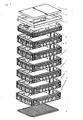
- Figure 1 shows an exploded perspective view of the Components of a manhole with modular manhole construction suitable for the inventive system is usable.
- the shaft consists of one Base plate 1, a plurality of interconnected frame elements 2, a Head frame 3, a resting on steel frame 4 and a lid 5, the can be closed by a locking device, not shown, the only can be operated with a special key or tool, so that the shaft can only be opened by a person authorized to do so.
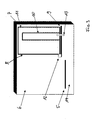
- FIG. 2 shows the plastic shaft or branch box in one compound state.
- the illustrated shaft contains five Frame elements 2 and has a clear width of 800 mm x 1,165 mm.
- the Shaft height is approx. 1,620 mm.
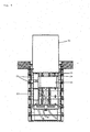
- FIG. 3 shows in a purely schematic representation the inventive device System.
- the shaft 6 which has a rectangular shape in plan, is in the Near a narrow side wall 7 a waterproof housing 8 is arranged, the one bottom plate 9, an ETS frame 10 arranged thereon and one Housing upper part 11, which in the manner of an airtight bell the ETS frame 10 covered and lockable with the bottom plate 9, which is caused by the Reference numeral 12 is indicated.
- the bottom plate 9 extend divisible Cable entries 13, waterproof by not shown sealing sets are closable.
- the distribution boards like telecom terminations, fiber optic patch panels etc. and optionally a power supply unit and a 230 V connection unit appropriate.
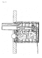
- the cables 16 through the bottom frame member in introduced the shaft 6, by breaking out of predetermined breaking areas in the housing 8 opposite narrow side wall. The remaining openings are closed by sealing plugs.
- the cables 16 extend below the bottom 15 through the cable space 14 and are along curved ramps 17 to the bottom plate 9 of the waterproof housing eighth with suitable seals 18 for a watertight closure of Floor plate 9 provide.
- the housing upper part 11, which consists of the side walls 19th and the upper ceiling wall 20 is made while an airtight bell or Hood forms, is releasably locked to the bottom plate 9.
- FIG. 5 shows a longitudinal section through the shaft in its width direction a view of the housing 8, the housing upper part 11 is pulled up, so that assembly or service work performed on the distribution device can be.
- the frame 10 which extends over the entire width of the Housing (and almost over the entire width of the shaft) extends areInstitut terminations 21, a 230 V connector unit 22, a power supply unit 23, a fiber optic pad 24 and a BGT installation space 25 are provided.
- the lower area of the installation space remains up to the height in which in the above described case water, free of built-in components.
- the upper housing part may be in the raised position by suitable means be locked.
- FIG. 6 schematically shows, in a size comparison, a working person who works in the Working position on the walkable, preferably Huaweistelzten bottom 15 kneels.
- the size comparison shows that there is enough space in the shaft before the opened housing to perform the required work.
Landscapes
- Physics & Mathematics (AREA)
- General Physics & Mathematics (AREA)
- Optics & Photonics (AREA)
- Casings For Electric Apparatus (AREA)
- Installation Of Indoor Wiring (AREA)
Abstract
Description
- Figur 1
- einen bei dem erfindungsgemäßen System verwendeten Schacht mit einem modularen Schachtaufbau;
- Figur 2
- den Schacht gemäß Figur 1 im zusammengesetzten Zustand;
- Figur 3
- das erfindungsgemäße System in einer rein schematischen Darstellung;
- Figur 4
- einen Längsschnitt durch den in das Erdreich eingebauten Schacht mit darin angeordnetem wasserdichten Gehäuse und verlegten Kabeln, wobei der Schnitt in Längsrichtung des Schachtes verläuft;
- Figur 5
- einen Vertikalschnitt durch den Schacht in dessen Breitenrichtung mit hochgezogenem Gehäuseoberteil;
- Figur 6
- eine Darstellung ähnlich Figur 4 mit hochgezogenem Gehäuseoberteil zur Veranschaulichung der Größenverhältnisse.
Claims (6)
- System zur Unterbringung von Verteilereinrichtungen oder dergleichen für Kupfer- und/oder Glasfaserkabel,
gekennzeichnet durch
einen mit einem verschließbaren Deckel (5) versehenen Schacht (6), der unterflur in den Boden einbaubar ist, und
ein in den Schacht (6) eingebautes wasserdichtes Gehäuse (8), in dem die Verteilereinrichtungen oder dergleichen untergebracht sind. - System nach Anspruch 1,
dadurch gekennzeichnet, daß das Gehäuse (8) eine wasserdichte Bodenplatte (9), wenigstens ein an der Bodenplatte befestigtes Gestell (10), an dem die Verteilereinrichtungen oder dergleichen angebracht sind, und ein aus Seitenwänden (19) und einer oberen Deckenwand (20) bestehendes Gehäuseoberteil (11) aufweist, das das wenigstens eine Gestell (10) überdeckt und wasserdicht mit der Bodenplatte (9) verbunden ist. - System nach Anspruch 2,
dadurch gekennzeichnet, daß das Gehäuseoberteil (11) einstückig ausgebildet ist und keine Wandöffnungen enthält. - System nach Anspruch 2 oder 3,
dadurch gekennzeichnet, daß das Gehäuseoberteil (11) nach dem Entriegeln nach oben ziehbar ist, so daß die Verteilereinrichtungen oder dergleichen für Montage- und Servicearbeiten zugänglich sind. - System nach einem der Ansprüche 1 bis 4,
dadurch gekennzeichnet, daß der Schacht (6) in seinem unteren Bereich einen Kabelaufnahmeraum (14) enthält, durch den die durch seitliche Öffnungen einer Schachtwand in den Schacht (6) eingeführten Kabel (16) zur Bodenplatte (9) des wasserdichten Gehäuses (8) verlaufen, und daß der Kabelaufnahmeraum (14) oben durch einen begehbaren Boden (15) begrenzt ist. - System nach Anspruch 5,
dadurch gekennzeichnet, daß vom Boden des Kabelaufnahmeraums (14) gebogene Rampen (17) zur Bodenplatte (9) des Gehäuses (8) führen.
Priority Applications (1)
| Application Number | Priority Date | Filing Date | Title |
|---|---|---|---|
| EP04009054A EP1587199B1 (de) | 2004-04-16 | 2004-04-16 | System zur Unterbringung von Verteilereinrichtungen von Kupfer- und/oder Glasfaserkabeln |
Applications Claiming Priority (1)
| Application Number | Priority Date | Filing Date | Title |
|---|---|---|---|
| EP04009054A EP1587199B1 (de) | 2004-04-16 | 2004-04-16 | System zur Unterbringung von Verteilereinrichtungen von Kupfer- und/oder Glasfaserkabeln |
Publications (2)
| Publication Number | Publication Date |
|---|---|
| EP1587199A1 true EP1587199A1 (de) | 2005-10-19 |
| EP1587199B1 EP1587199B1 (de) | 2011-12-21 |
Family
ID=34924623
Family Applications (1)
| Application Number | Title | Priority Date | Filing Date |
|---|---|---|---|
| EP04009054A Expired - Lifetime EP1587199B1 (de) | 2004-04-16 | 2004-04-16 | System zur Unterbringung von Verteilereinrichtungen von Kupfer- und/oder Glasfaserkabeln |
Country Status (1)
| Country | Link |
|---|---|
| EP (1) | EP1587199B1 (de) |
Cited By (4)
| Publication number | Priority date | Publication date | Assignee | Title |
|---|---|---|---|---|
| EP1617715A2 (de) | 2004-07-14 | 2006-01-18 | Berthold Sichert GmbH | Dachmodul-Bausatz für Verteilerschränke |
| FR3017022A1 (fr) * | 2014-01-24 | 2015-07-31 | Syndicat Intercommunal Pour Le Gaz Et L Electricite En Ile De France | Chambre pour un reseau de communications electroniques |
| EP4286595A1 (de) * | 2022-06-03 | 2023-12-06 | Langmatz GmbH | Schacht |
| EP4286596A1 (de) * | 2022-06-03 | 2023-12-06 | Langmatz GmbH | Schacht |
Citations (7)
| Publication number | Priority date | Publication date | Assignee | Title |
|---|---|---|---|---|
| DE1952453U (de) | 1966-10-26 | 1966-12-29 | Krone Kg | Ueberflutsicherer behaelter zur aufnahme elektrischer bauteile. |
| US3482030A (en) * | 1968-09-30 | 1969-12-02 | Pepco Products Corp | Underground electrical conductor housing with inner bell-jar housing |
| DE3322584A1 (de) | 1983-06-23 | 1983-11-24 | Krone Gmbh, 1000 Berlin | Gehaeuse in unterflurausfuehrung, insbesondere fuer fernmeldetechnische geraete |
| US5210374A (en) | 1990-05-21 | 1993-05-11 | Channell William H | Terminal housing for buried communication lines |
| EP0929136A1 (de) * | 1998-01-07 | 1999-07-14 | Odink & Koenderink B.V. | Zum versenkten Aufstellen auf (semi) öffentlichem Boden bestimmte Energieverteilungsstation zur Spannungsentnahme durch Privatpersonen oder Betriebe |
| EP0994543A1 (de) * | 1998-10-14 | 2000-04-19 | Alstom France SA | Wasserschutzvorrichtung für einen versenkbaren, unterirdischen Schaltschrank |
| EP1223651A1 (de) * | 2001-01-12 | 2002-07-17 | van Eijndhoven International B.V. | Im Erdreich einsetzbares Kabelverbindungsgehäuse |
-
2004
- 2004-04-16 EP EP04009054A patent/EP1587199B1/de not_active Expired - Lifetime
Patent Citations (7)
| Publication number | Priority date | Publication date | Assignee | Title |
|---|---|---|---|---|
| DE1952453U (de) | 1966-10-26 | 1966-12-29 | Krone Kg | Ueberflutsicherer behaelter zur aufnahme elektrischer bauteile. |
| US3482030A (en) * | 1968-09-30 | 1969-12-02 | Pepco Products Corp | Underground electrical conductor housing with inner bell-jar housing |
| DE3322584A1 (de) | 1983-06-23 | 1983-11-24 | Krone Gmbh, 1000 Berlin | Gehaeuse in unterflurausfuehrung, insbesondere fuer fernmeldetechnische geraete |
| US5210374A (en) | 1990-05-21 | 1993-05-11 | Channell William H | Terminal housing for buried communication lines |
| EP0929136A1 (de) * | 1998-01-07 | 1999-07-14 | Odink & Koenderink B.V. | Zum versenkten Aufstellen auf (semi) öffentlichem Boden bestimmte Energieverteilungsstation zur Spannungsentnahme durch Privatpersonen oder Betriebe |
| EP0994543A1 (de) * | 1998-10-14 | 2000-04-19 | Alstom France SA | Wasserschutzvorrichtung für einen versenkbaren, unterirdischen Schaltschrank |
| EP1223651A1 (de) * | 2001-01-12 | 2002-07-17 | van Eijndhoven International B.V. | Im Erdreich einsetzbares Kabelverbindungsgehäuse |
Cited By (5)
| Publication number | Priority date | Publication date | Assignee | Title |
|---|---|---|---|---|
| EP1617715A2 (de) | 2004-07-14 | 2006-01-18 | Berthold Sichert GmbH | Dachmodul-Bausatz für Verteilerschränke |
| EP1617715A3 (de) * | 2004-07-14 | 2007-12-12 | Berthold Sichert GmbH | Dachmodul-Bausatz für Verteilerschränke |
| FR3017022A1 (fr) * | 2014-01-24 | 2015-07-31 | Syndicat Intercommunal Pour Le Gaz Et L Electricite En Ile De France | Chambre pour un reseau de communications electroniques |
| EP4286595A1 (de) * | 2022-06-03 | 2023-12-06 | Langmatz GmbH | Schacht |
| EP4286596A1 (de) * | 2022-06-03 | 2023-12-06 | Langmatz GmbH | Schacht |
Also Published As
| Publication number | Publication date |
|---|---|
| EP1587199B1 (de) | 2011-12-21 |
Similar Documents
| Publication | Publication Date | Title |
|---|---|---|
| EP0849850B1 (de) | Freiluftgehäuse zur Aufnahme von Telekommunikationseinrichtungen und Verfahren zur Unterstützung von Freiluftgehäusen | |
| DE10314897B3 (de) | System zur Unterbringung von Verteilereinrichtungen von Kupfer- und/oder Glasfaserkabeln | |
| DE60220496T2 (de) | Schreibtisch und schreibtischsystem | |
| DE3423184C2 (de) | Unterflurstation für Kabelverzweigereinrichtungen der Fernmeldetechnik | |
| EP0878808B1 (de) | Elektrische Umspannstation | |
| DE3322584C2 (de) | Gehäuse in Unterflurausführung, insbesondere für fernmeldetechnische Geräte | |
| EP0929136B1 (de) | Zum versenkten Aufstellen auf (semi) öffentlichem Boden bestimmte Energieverteilungsstation zur Spannungsentnahme durch Privatpersonen oder Betriebe | |
| DE3900021C2 (de) | ||
| EP1587199B1 (de) | System zur Unterbringung von Verteilereinrichtungen von Kupfer- und/oder Glasfaserkabeln | |
| DE1949694C3 (de) | Unterirdisch angeordneter Niederspannungsverteiler | |
| EP0487802A1 (de) | Verteiler für die Nachrichtentechnik | |
| EP0905842B1 (de) | Zum Aufstellen auf semi-öffentlichem Boden bestimmte Energieverteilungsstation zur Spannungsentnahme durch Privatpersonen oder Betriebe | |
| DE69607020T2 (de) | Kunststoffabzweigdose mit steckdosen | |
| DE102019129487B4 (de) | Vorrichtung für das Glasfaser-Management | |
| DE19854358A1 (de) | Fundamentwanne für energietechnische Anlagen | |
| DE102018129234B4 (de) | Kollokationsmodul, Modulbaugruppe sowie Glasfaserverteilereinrichtung | |
| EP0599442B1 (de) | Fernsprechnebenstellenanlage | |
| DE102006056962B4 (de) | Anordnung aus einem Gehäuse mit Telekommunikationseinbauten und einer Energieanschlusssäule | |
| EP1239564B1 (de) | Installationsverteiler | |
| DE3342566A1 (de) | Unterflur-gehaeuse, insbesondere fuer fernmeldetechnische geraete | |
| DE8418720U1 (de) | Sockel für Kabelverzweigergehäuse | |
| DE102013000910B4 (de) | Glasfaser-Abschlusspunkt | |
| DE29908950U1 (de) | Telekommunikationseinrichtung für Sprach- und/oder Datenübertragung | |
| WO1995027324A1 (de) | Modulare telekommunikationsanlage | |
| EP0942442A2 (de) | Umspannstation in Kompaktbauweise |
Legal Events
| Date | Code | Title | Description |
|---|---|---|---|
| PUAI | Public reference made under article 153(3) epc to a published international application that has entered the european phase |
Free format text: ORIGINAL CODE: 0009012 |
|
| 17P | Request for examination filed |
Effective date: 20050323 |
|
| AK | Designated contracting states |
Kind code of ref document: A1 Designated state(s): AT BE BG CH CY CZ DE DK EE ES FI FR GB GR HU IE IT LI LU MC NL PL PT RO SE SI SK TR |
|
| AX | Request for extension of the european patent |
Extension state: AL HR LT LV MK |
|
| AKX | Designation fees paid |
Designated state(s): CZ HU SK |
|
| REG | Reference to a national code |
Ref country code: DE Ref legal event code: 8566 |
|
| 17Q | First examination report despatched |
Effective date: 20090323 |
|
| GRAP | Despatch of communication of intention to grant a patent |
Free format text: ORIGINAL CODE: EPIDOSNIGR1 |
|
| RAP1 | Party data changed (applicant data changed or rights of an application transferred) |
Owner name: LANGMATZ GMBH |
|
| GRAS | Grant fee paid |
Free format text: ORIGINAL CODE: EPIDOSNIGR3 |
|
| GRAA | (expected) grant |
Free format text: ORIGINAL CODE: 0009210 |
|
| AK | Designated contracting states |
Kind code of ref document: B1 Designated state(s): CZ HU SK |
|
| REG | Reference to a national code |
Ref country code: SK Ref legal event code: T3 Ref document number: E 11240 Country of ref document: SK |
|
| PLBE | No opposition filed within time limit |
Free format text: ORIGINAL CODE: 0009261 |
|
| STAA | Information on the status of an ep patent application or granted ep patent |
Free format text: STATUS: NO OPPOSITION FILED WITHIN TIME LIMIT |
|
| 26N | No opposition filed |
Effective date: 20120924 |
|
| REG | Reference to a national code |
Ref country code: SK Ref legal event code: MM4A Ref document number: E 11240 Country of ref document: SK Effective date: 20120416 |
|
| PG25 | Lapsed in a contracting state [announced via postgrant information from national office to epo] |
Ref country code: SK Free format text: LAPSE BECAUSE OF NON-PAYMENT OF DUE FEES Effective date: 20120416 |
|
| REG | Reference to a national code |
Ref country code: HU Ref legal event code: AG4A Ref document number: E014632 Country of ref document: HU |
|
| PGFP | Annual fee paid to national office [announced via postgrant information from national office to epo] |
Ref country code: CZ Payment date: 20140409 Year of fee payment: 11 |
|
| PGFP | Annual fee paid to national office [announced via postgrant information from national office to epo] |
Ref country code: HU Payment date: 20140429 Year of fee payment: 11 |
|
| PG25 | Lapsed in a contracting state [announced via postgrant information from national office to epo] |
Ref country code: HU Free format text: LAPSE BECAUSE OF NON-PAYMENT OF DUE FEES Effective date: 20150417 Ref country code: CZ Free format text: LAPSE BECAUSE OF NON-PAYMENT OF DUE FEES Effective date: 20150416 |