EP1586726A1 - Opening and closing mechanism for a vehicle door - Google Patents
Opening and closing mechanism for a vehicle door Download PDFInfo
- Publication number
- EP1586726A1 EP1586726A1 EP05007233A EP05007233A EP1586726A1 EP 1586726 A1 EP1586726 A1 EP 1586726A1 EP 05007233 A EP05007233 A EP 05007233A EP 05007233 A EP05007233 A EP 05007233A EP 1586726 A1 EP1586726 A1 EP 1586726A1
- Authority
- EP
- European Patent Office
- Prior art keywords
- handle
- locking
- locking member
- branch
- leg
- Prior art date
- Legal status (The legal status is an assumption and is not a legal conclusion. Google has not performed a legal analysis and makes no representation as to the accuracy of the status listed.)
- Granted
Links
- 230000007246 mechanism Effects 0.000 title claims abstract description 31
- 238000004804 winding Methods 0.000 claims description 8
- 230000005540 biological transmission Effects 0.000 claims description 7
- 230000003213 activating effect Effects 0.000 abstract 1
- 210000000056 organ Anatomy 0.000 description 3
- 230000000694 effects Effects 0.000 description 2
- 230000001133 acceleration Effects 0.000 description 1
- 230000000295 complement effect Effects 0.000 description 1
Images


Classifications
-
- E—FIXED CONSTRUCTIONS
- E05—LOCKS; KEYS; WINDOW OR DOOR FITTINGS; SAFES
- E05B—LOCKS; ACCESSORIES THEREFOR; HANDCUFFS
- E05B85/00—Details of vehicle locks not provided for in groups E05B77/00 - E05B83/00
- E05B85/10—Handles
- E05B85/14—Handles pivoted about an axis parallel to the wing
- E05B85/16—Handles pivoted about an axis parallel to the wing a longitudinal grip part being pivoted at one end about an axis perpendicular to the longitudinal axis of the grip part
-
- E—FIXED CONSTRUCTIONS
- E05—LOCKS; KEYS; WINDOW OR DOOR FITTINGS; SAFES
- E05B—LOCKS; ACCESSORIES THEREFOR; HANDCUFFS
- E05B77/00—Vehicle locks characterised by special functions or purposes
- E05B77/02—Vehicle locks characterised by special functions or purposes for accident situations
-
- E—FIXED CONSTRUCTIONS
- E05—LOCKS; KEYS; WINDOW OR DOOR FITTINGS; SAFES
- E05B—LOCKS; ACCESSORIES THEREFOR; HANDCUFFS
- E05B13/00—Devices preventing the key or the handle or both from being used
- E05B13/002—Devices preventing the key or the handle or both from being used locking the handle
Definitions
- the present invention relates to an opening / closing mechanism of car door.
- This mechanism is of the type comprising a pivotally mounted handle on a base around an axis substantially parallel to the plane of the door and substantially perpendicular to the longitudinal axis of the handle.
- a handle usually includes two branches protruding from its ends, including a pivoting branch pivotally connected to the base and an actuating branch acting on a set of transmission achieving the unlocking of the door.
- the documents US 6,447,030 and EP 1,286,009 illustrate existing mechanisms.
- the present invention aims to remedy these disadvantages.
- Its main purpose is therefore to provide a handle mechanism aforementioned type, which allows a perfectly satisfactory locking of the handle.
- Another object of the invention is to provide a mechanism which the actuation remains simple and natural for the user.
- Yet another object of the invention is to provide a mechanism having a structure that remains relatively simple, with reliable operation.
- Such a pivoting locking member normally maintained in locking position by the elastic member, allows locking permanent and reliable handle in the locked position of the door, until actuation of the control member is achieved.
- This locking member retains a simple structure to perform and has reliable operation.
- control member on the handle allows a simple and natural actuation of the locking member simultaneously with the actuation of the handle.
- the locking member may comprise a locking arm, comprising a gripping surface for engagement with the base, and an actuating branch connected to this locking arm, forming a angle with the latter, this actuating branch being located at proximity of the control member, which acts on this branch when actuated.
- the structure of the mechanism according to the invention is thus particularly simple.
- the locking arm and the actuating arm that includes the locking member can be in one piece.
- the locking member may comprise at least one housing or a projection receiving a portion of the elastic member, allowing an assembly easy mechanism.
- the locking member can comprise a cavity for receiving the elastic member, this cavity being delimited by a wall whose face opposite the cavity forms a control member.
- the elastic member may have two clean windings to come into engagement on protrusions of the locking member, a intermediate branch connecting these two windings, and at least one other branch extending from at least one winding, said branch intermediate bearing against the locking member or the handle while the said other branch bears against, respectively, the handle or the locking member.
- the locking member may be independent of a branch fixed actuation that includes the handle, and be mounted on this branch fixed actuation.
- the locking arm of this locking member can also constitute the actuating branch of the handle itself.
- this locking arm may comprise at least one boss at level of its free end, coming into engagement, in the locking position of the door, in a corresponding housing fitted on the base.
- control member may be arranged on the face of the handle opposite to the base. Preferably, however, this control member is located on the face of the handle facing the base, in one location as it stands substantially next to the user index when that the latter grasps the handle.
- the control member may be constituted by a button that can be pressed to actuate the locking member.
- FIG. 1 represents a door opening / closing mechanism 1 of a motor vehicle, comprising a base 2, a set of transmission 3, a handle 4, a locking member 5 and a spring 6.
- the base 2 is intended to be fixed to the door, against the plate of it. It has a central portion 10, a rear portion 11 and a front part 12.
- the central portion 10 has a recessed concave shape, allowing the passing the user's fingers around the handle 4, and delimits a receiving housing 13 of the transmission assembly 3.
- This set of transmission 3 comprises a pivoting body 15 provided with a radial wing 16, a pin spring 17 clean to maintain normally this pivoting body 15 in a position corresponding to the locking of the door and a lever 18 integral with the body 15, connected to an actuating cable (not shown) which controls the movement of the door opening / closing latch.
- the radial wing 16 is facing a branch actuator 30 that the handle 4 has and is actuated by this actuating branch 30 when the handle 4 is rotated, as well as this will be explained later.
- the rear portion 11 defines a housing 20 for receiving a branch of pivoting 31 that includes the handle 4 and includes a crossbar rounded 21 (see Figures 1A, 2 and 3) around which this branch pivots 31.
- the front portion 12 defines a housing 22 for receiving said actuating branch 30 and comprises, at this housing 22, two grooves 23 L-shaped, visible in particular in Figure 1A.
- the parts of these grooves 23 (those perpendicular to the length of the base 2), are adapted to receive sliding two bosses side 24 that includes the actuating branch 30, and the parts secondary (those parallel to the length of the base 2) of these grooves 23 are adapted to receive these bosses 24 in the locking position of the handle 4.
- the handle 4 comprises a body 25 on which is fixed a hood hubcap 26, this fixing being carried out by means of projections of snap-fitting 27 arranged on the body 25 and complementary cavities fitted on the hood 26.
- the pivoting branch 31 is integral with the body 25. It presents a curved shape, allowing its engagement in housing 20 and includes a notch 32 at its free end, allowing its engagement pivotally on the rounded cross member 21 in this housing 20.
- the body 25 comprises a pair of coaxial holes 35 receiving an axis 36 pivotally mounting the locking member 5 on this handle 4.
- the body 25 defines a housing 37 opening on the face of the handle 4 turned towards the base 2.
- the locking member 5 has two branches substantially perpendiculars 30, 40 and comprises, at the junction zone of these branches 30, 40, a hole 41 for receiving the axis 36.
- the locking arm 30 forms the aforementioned actuating arm of the transmission assembly 3. It has a curved free end 42, intended to cooperate with the radial flange 16 of the pivoting body 15, and has the two lateral bosses 24 on either side of this end free 42.
- the branch 40 constitutes an actuating branch of the pivoting of the locking member 5, and is, after mounting, inside the 37. At its free end, it forms, on the side of the body 25, a cavity 43 for receiving the spring 6 and, on the side of the base 2, a boss rounded 44.
- the length of this branch 40 is such that this boss 44 is found significantly next to the user index when that user engages his fingers around the handle 4, this boss 44 forming and a button for actuating the locking member 5 in pivoting.
- the spring 6 is a coil spring.
- the locking member 5 is normally maintained by the spring 6 which tends to spread the branch 40 of the body 25, in the position represented in FIG. 2. In this position, the bosses 24 are engaged in said secondary portions of the grooves 23, so that the organ of locking 5, and therefore the handle 4, is locked relative to the base 2.
- the user grasps the handle 4 and presses with his index the button that forms the boss 44, thus moving the body of locking 5 in the position shown in Figure 3.
- the bosses 24 are then extracted from said secondary portions of the grooves 23, thus releasing the pivoting of the handle 4 and allowing the opening of the door.
- This opening results from the action of the end 42 against the wing 16, realizing a pivoting the body 15 and actuating the cable acting on the latch opening / closing the door.
- FIG. 4 shows a mechanism 1 comprising a handle 4 provided with of a fixed actuating branch 50, integral with the body 25.
- the body 25 comprises a locking member 5 provided with its own locking arm 51, here formed by a pair of hooks, and the base 2 comprises two lugs 52 integral with it, behind which hooks forming this locking arm 51 come engage in the locking position of the handle 4.
- the base 2 receives a seal 53, closing the housing 22.
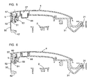
- the locking member 5 comprises two coaxial pivots 55 making projecting from its two lateral faces, and delimits a housing 56 in which protruding, in the direction of one another, two coaxial lugs 57 (see FIGS. and 6).
- the spring 6 is constituted by a wire folded so as to form two windings 58 adapted to be engaged on these pins 57, a branch intermediate 59 between these two windings and two extremal branches rectilinear 60.
- the intermediate branch 59 bears against the body 25 while the two extremal branches 60 bear against a wall of the locking member 5 which delimits the housing 56.
- the button 44 is independent of the branch 40 and simply takes against it for the actuation of the locking member 5 in pivoting.
- mechanism 1 is similar to the one previously described for the first version, and is illustrated in Figures 5 and 6, which are sectional views through the hook of the branch 51 located in the background in FIG.
- the invention thus provides a door opening / closing mechanism of a motor vehicle allowing a perfectly satisfactory locking of the handle 4, having an actuation which remains simple and natural for the user, and having a structure that remains relatively simple, with a reliable operation.
- the organ of control can be an electrical system, in particular actuated by waves, and / or the mechanism may include such a system; the controller of cooperate directly with the organ of royal life I August through one or more transmission parts placed between them.
Abstract
Description
La présente invention concerne un mécanisme d'ouverture/fermeture de portière de véhicule automobile.The present invention relates to an opening / closing mechanism of car door.
Ce mécanisme est du type comprenant une poignée montée pivotante sur une embase autour d'un axe sensiblement parallèle au plan de la portière et sensiblement perpendiculaire à l'axe longitudinal de la poignée. Une telle poignée comprend généralement deux branches faisant saillie de ses extrémités, dont une branche de pivotement reliée de manière pivotante à l'embase et une branche d'actionnement agissant sur un ensemble de transmission réalisant le déverrouillage de la portière. Les documents US 6,447,030 et EP 1 286 009 illustrent des mécanismes existants.This mechanism is of the type comprising a pivotally mounted handle on a base around an axis substantially parallel to the plane of the door and substantially perpendicular to the longitudinal axis of the handle. Such a handle usually includes two branches protruding from its ends, including a pivoting branch pivotally connected to the base and an actuating branch acting on a set of transmission achieving the unlocking of the door. The documents US 6,447,030 and EP 1,286,009 illustrate existing mechanisms.
Il est connu de réaliser un tel mécanisme sans verrouillage du mouvement de la poignée lorsque que le véhicule roule, ce qui peut occasionner une ouverture intempestive de la portière en cas d'accident, soit sous l'effet d'accélérations, soit sous l'effet de déformations subies par la portière et/ou la carrosserie du véhicule, particulièrement en cas de choc latéral.It is known to realize such a mechanism without locking the movement of the handle while the vehicle is moving, which may causing an accidental opening of the door in the event of an accident, under the effect of accelerations, or under the effect of deformations suffered by the door and / or the body of the vehicle, particularly in case of impact lateral.
Il est par ailleurs connu de réaliser des mécanismes d'ouverture/fermeture de portière de véhicules automobiles comprenant des moyens de verrouillage de la poignée en position de verrouillage de la portière en cas d'accident, notamment des systèmes à inertie incluant des masselottes.It is also known to realize mechanisms opening / closing of motor vehicle doors comprising locking means of the handle in the locking position of the door in the event of an accident, including inertia systems including weights.
Les systèmes existants s'avèrent toutefois ne pas permettre un blocage de la poignée parfaitement satisfaisant en cas d'accident et ont pour inconvénient d'avoir des structures relativement complexes.Existing systems, however, do not allow to block handle perfectly satisfactory in case of accident and have for disadvantage of having relatively complex structures.
La présente invention vise à remédier à ces inconvénients.The present invention aims to remedy these disadvantages.
Son objectif principal est donc de fournir un mécanisme à poignée du type précité, qui permette un verrouillage parfaitement satisfaisant de la poignée.Its main purpose is therefore to provide a handle mechanism aforementioned type, which allows a perfectly satisfactory locking of the handle.
Un autre objectif de l'invention est de fournir un mécanisme dont l'actionnement reste simple et naturel pour l'utilisateur.Another object of the invention is to provide a mechanism which the actuation remains simple and natural for the user.
Un autre objectif encore de l'invention est de fournir un mécanisme ayant une structure qui reste relativement simple, avec un fonctionnement fiable. Yet another object of the invention is to provide a mechanism having a structure that remains relatively simple, with reliable operation.
Pour atteindre ces objectifs, la poignée du mécanisme selon l'invention comprend :
- un organe de verrouillage pivotant, monté au niveau de la branche d'actionnement de cette poignée, cet organe étant pivotant entre une position de verrouillage de la poignée, dans laquelle il vient en prise avec l'embase, et une position de déverrouillage de la poignée, dans laquelle il n'est pas en prise avec l'embase ;
- un organe élastique maintenant normalement l'organe de verrouillage en position de verrouillage, et
- un organe de commande du pivotement de l'organe de verrouillage vers sa position de déverrouillage.
- a pivoting locking member, mounted at the actuating leg of this handle, this member being pivotable between a locking position of the handle, in which it engages the base, and an unlocking position of the handle, in which it is not engaged with the base;
- an elastic member normally holding the locking member in the locking position, and
- a control member for pivoting the locking member towards its unlocking position.
Un tel organe de verrouillage pivotant, maintenu normalement en position de verrouillage par l'organe élastique, permet un verrouillage permanent et fiable de la poignée en position de verrouillage de la portière, tant qu'un actionnement de l'organe de commande n'est pas réalisé.Such a pivoting locking member, normally maintained in locking position by the elastic member, allows locking permanent and reliable handle in the locked position of the door, until actuation of the control member is achieved.
Cet organe de verrouillage conserve une structure simple à réaliser et a un fonctionnement fiable.This locking member retains a simple structure to perform and has reliable operation.
La présence de l'organe de commande sur la poignée permet un actionnement simple et naturel de l'organe de verrouillage simultanément à l'actionnement de la poignée.The presence of the control member on the handle allows a simple and natural actuation of the locking member simultaneously with the actuation of the handle.
L'organe de verrouillage peut comprendre une branche de verrouillage, comprenant une surface de prise pour sa venue en prise avec l'embase, et une branche d'actionnement reliée à cette branche de verrouillage, formant un angle avec cette dernière, cette branche d'actionnement étant située à proximité de l'organe de commande, lequel agit sur cette branche d'actionnement lorsqu'il est actionné.The locking member may comprise a locking arm, comprising a gripping surface for engagement with the base, and an actuating branch connected to this locking arm, forming a angle with the latter, this actuating branch being located at proximity of the control member, which acts on this branch when actuated.
La structure du mécanisme selon l'invention est ainsi particulièrement simple.The structure of the mechanism according to the invention is thus particularly simple.
La branche de verrouillage et la branche d'actionnement que comprend l'organe de verrouillage peuvent être d'un seul tenant.The locking arm and the actuating arm that includes the locking member can be in one piece.
L'organe de verrouillage peut comprendre au moins un logement ou une saillie recevant une partie de l'organe élastique, permettant un assemblage facile du mécanisme. Notamment, l'organe de verrouillage peut comprendre une cavité de réception de l'organe élastique, cette cavité étant délimitée par une paroi dont la face opposée à la cavité forme d'organe de commande. Alternativement, l'organe élastique peut présenter deux enroulements propres à venir en engagement sur des saillies de l'organe de verrouillage, une branche intermédiaire reliant ces deux enroulements, et au moins une autre branche se prolongeant à partir d'au moins un enroulement, ladite branche intermédiaire venant en appui contre l'organe de verrouillage ou la poignée tandis que ladite autre branche prend appui contre, respectivement, la poignée ou l'organe de verrouillage.The locking member may comprise at least one housing or a projection receiving a portion of the elastic member, allowing an assembly easy mechanism. In particular, the locking member can comprise a cavity for receiving the elastic member, this cavity being delimited by a wall whose face opposite the cavity forms a control member. Alternatively, the elastic member may have two clean windings to come into engagement on protrusions of the locking member, a intermediate branch connecting these two windings, and at least one other branch extending from at least one winding, said branch intermediate bearing against the locking member or the handle while the said other branch bears against, respectively, the handle or the locking member.
L'organe de verrouillage peut être indépendant d'une branche d'actionnement fixe que comprend la poignée, et être monté sur cette branche d'actionnement fixe.The locking member may be independent of a branch fixed actuation that includes the handle, and be mounted on this branch fixed actuation.
La branche de verrouillage de cet organe de verrouillage peut également constituer la branche d'actionnement de la poignée elle-même. Dans ce cas, cette branche de verrouillage peut comprendre au moins un bossage au niveau de son extrémité libre, venant s'engager, en position de verrouillage de la portière, dans un logement correspondant aménagé sur l'embase.The locking arm of this locking member can also constitute the actuating branch of the handle itself. In that case, this locking arm may comprise at least one boss at level of its free end, coming into engagement, in the locking position of the door, in a corresponding housing fitted on the base.
L'organe de commande peut être aménagé sur la face de la poignée opposée à l'embase. De préférence, toutefois, cet organe de commande est aménagé sur la face de la poignée tournée vers l'embase, en un emplacement tel qu'il se trouve sensiblement en regard de l'index de l'utilisateur lorsque que ce dernier saisit la poignée.The control member may be arranged on the face of the handle opposite to the base. Preferably, however, this control member is located on the face of the handle facing the base, in one location as it stands substantially next to the user index when that the latter grasps the handle.
L'actionnement de cet organe de commande est ainsi réalisé selon un geste simple et naturel.The actuation of this control member is thus performed according to a simple and natural gesture.
L'organe de commande peut être constitué par un bouton pouvant être pressé pour actionner l'organe de verrouillage.The control member may be constituted by a button that can be pressed to actuate the locking member.
L'invention sera bien comprise, et d'autres caractéristiques et avantages de celle-ci apparaítront, en référence au dessin schématique annexé, représentant, à titre d'exemples non limitatifs, deux formes de réalisation possibles du mécanisme qu'elle concerne.The invention will be well understood, and other features and advantages of it will appear, with reference to the attached schematic drawing, representative, by way of non-limiting examples, two embodiments the mechanism it concerns.
La figure 1 en est une vue en perspective éclatée, selon une première
forme de réalisation ;
Par simplification, les parties ou éléments d'une forme de réalisation qui se retrouvent de manière identique ou similaire dans une autre forme de réalisation seront identifiés par les mêmes références numériques et ne seront pas à nouveau décrits.For simplicity, the parts or elements of an embodiment which are found in the same or similar way in another form of realization will be identified by the same numerical references and will not be not described again.
La figure 1 représente un mécanisme 1 d'ouverture/fermeture de portière
de véhicule automobile, comprenant une embase 2, un ensemble de
transmission 3, une poignée 4, un organe de verrouillage 5 et un ressort 6.FIG. 1 represents a door opening /
L'embase 2 est destinée à être fixée à la portière, contre la tôle de
celle-ci. Elle présente une partie centrale 10, une partie arrière 11 et une
partie avant 12.The
La partie centrale 10 présente une forme évidée concave, permettant le
passage des doigts de l'utilisateur autour de la poignée 4, et délimite un
logement 13 de réception de l'ensemble de transmission 3. Cet ensemble de
transmission 3 comprend un corps pivotant 15 pourvu d'une aile radiale 16, un
ressort en épingle 17 propre à maintenir normalement ce corps pivotant 15
dans une position correspondant au verrouillage de la portière et un levier 18
solidaire du corps 15, relié à un câble d'actionnement (non représenté) qui
commande le mouvement du loquet d'ouverture/fermeture de la portière.The
Après montage, l'aile radiale 16 se trouve en regard d'une branche
d'actionnement 30 que comporte la poignée 4 et est actionnée par cette
branche d'actionnement 30 lorsque la poignée 4 est pivotée, ainsi que cela
sera explicité plus loin.After assembly, the
La partie arrière 11 délimite un logement 20 de réception d'une branche
de pivotement 31 que comprend la poignée 4 et comprend une traverse
arrondie 21 (cf. figures 1A, 2 et 3) autour de laquelle pivote cette branche 31.The
La partie avant 12 délimite un logement 22 de réception de ladite
branche d'actionnement 30 et comprend, au niveau de ce logement 22, deux
rainures 23 en formes de L, visibles en particulier sur la figure 1A. Les parties
principales de ces rainures 23 (celles perpendiculaires à la longueur de
l'embase 2), sont propres à recevoir à coulissement deux bossages
latéraux 24 que comprend la branche d'actionnement 30, et les parties
secondaires (celles parallèles à la longueur de l'embase 2) de ces rainures 23
sont propres à recevoir ces bossages 24 en position de verrouillage de la
poignée 4.The
La poignée 4 comprend un corps 25 sur lequel est fixé un capot
enjoliveur 26, cette fixation étant réalisée au moyen de saillies
d'encliquetage 27 aménagées sur le corps 25 et de cavités complémentaires
aménagées sur le capot 26.The
La branche de pivotement 31 est solidaire du corps 25. Elle présente une
forme recourbée, permettant son engagement dans le logement 20 et
comprend une encoche 32 à son extrémité libre, permettant son engagement
à pivotement sur la traverse arrondie 21 présente dans ce logement 20.The
A son extrémité opposée à celle comportant la branche de
pivotement 31, le corps 25 comprend une paire de trous coaxiaux 35 recevant
un axe 36 de montage pivotant de l'organe de verrouillage 5 sur cette
poignée 4.At the opposite end to the one with the branch of
pivoting 31, the
En arrière de ces trous 35, le corps 25 délimite un logement 37 s'ouvrant
sur la face de la poignée 4 tournée vers l'embase 2.Behind these
L'organe de verrouillage 5 présente deux branches sensiblement
perpendiculaires 30, 40 et comprend, au niveau de la zone de jonction de ces
branches 30, 40, un trou 41 de réception de l'axe 36.The
La branche de verrouillage 30 forme la branche précitée d'actionnement
de l'ensemble de transmission 3. Elle présente une extrémité libre recourbée
42, destinée à coopérer avec l'aile radiale 16 du corps pivotant 15, et
comporte les deux bossages latéraux 24 de part et d'autre de cette extrémité
libre 42.The
La branche 40 constitue une branche d'actionnement du pivotement de
l'organe de verrouillage 5, et se trouve, après montage, à l'intérieur du
logement 37. A son extrémité libre, elle forme, du côté du corps 25, une
cavité 43 de réception du ressort 6 et, du côté de l'embase 2, un bossage
arrondi 44. La longueur de cette branche 40 est telle que ce bossage 44 se
trouve sensiblement en regard de l'index de l'utilisateur lorsque que cet
utilisateur engage ses doigts autour de la poignée 4, ce bossage 44 formant
ainsi un bouton d'actionnement de l'organe de verrouillage 5 en pivotement.The
Le ressort 6 est un ressort hélicoïdal.The
En pratique, l'organe de verrouillage 5 est maintenu normalement, par le
ressort 6 qui tend à écarter la branche 40 du corps 25, dans la position
représentée sur la figure 2. Dans cette position, les bossages 24 sont engagés
dans lesdites portions secondaires des rainures 23, de sorte que l'organe de
verrouillage 5, et donc la poignée 4, est verrouillé par rapport à l'embase 2.In practice, the locking
Pour ouvrir la portière, l'utilisateur saisit la poignée 4 et presse avec son
index le bouton que forme le bossage 44, déplaçant ainsi l'organe de
verrouillage 5 dans la position représentée sur la figure 3. Les bossages 24
sont alors extraits desdites portions secondaires des rainures 23, libérant ainsi
le pivotement de la poignée 4 et permettant l'ouverture de la portière. Cette
ouverture résulte de l'action de l'extrémité 42 contre l'aile 16, réalisant un
pivotement du corps 15 et l'actionnement du câble agissant sur le loquet
d'ouverture/fermeture de la portière.To open the door, the user grasps the
La figure 4 montre un mécanisme 1 comprenant une poignée 4 pourvue
d'une branche d'actionnement 50 fixe, solidaire du corps 25. Dans cette
version du mécanisme 1, le corps 25 comprend un organe de verrouillage 5
muni de sa propre branche de verrouillage 51, ici formée par une paire de
crochets, et l'embase 2 comprend deux ergots 52 solidaires d'elle, derrière
lesquels les crochets formant cette branche de verrouillage 51 viennent
s'engager en position de verrouillage de la poignée 4.FIG. 4 shows a
L'embase 2 reçoit un joint 53, refermant le logement 22. The
L'organe de verrouillage 5 comprend deux pivots coaxiaux 55 faisant
saillie de ses deux faces latérales, et délimite un logement 56 dans lequel font
saillie, en direction de l'un de l'autre, deux ergots coaxiaux 57 (cf. figures 5
et 6).The locking
Le ressort 6 est constitué par un fil métallique plié de manière à former
deux enroulements 58 propres à être engagés sur ces ergots 57, une branche
intermédiaire 59 entre ces deux enroulements et deux branches extrémales
rectilignes 60. La branche intermédiaire 59 prend appui contre le corps 25
tandis que les deux branches extrémales 60 prennent appui contre une paroi
de l'organe de verrouillage 5 qui délimite le logement 56.The
Le bouton 44 est indépendant de la branche 40 et prend simplement
appui contre elle pour l'actionnement de l'organe de verrouillage 5 en
pivotement.The
Le fonctionnement du mécanisme 1 selon cette deuxième version est
similaire à celui décrit précédemment concernant la première version, et est
illustré par les figures 5 et 6, lesquelles sont des vues en section passant par
le crochet de la branche 51 situé à l'arrière-plan sur la figure 4.The operation of
L'invention fournit ainsi un mécanisme d'ouverture/fermeture de portière
de véhicule automobile permettant un verrouillage parfaitement satisfaisant de
la poignée 4, ayant un actionnement qui reste simple et naturel pour
l'utilisateur, et ayant une structure qui reste relativement simple, avec un
fonctionnement fiable.The invention thus provides a door opening / closing mechanism
of a motor vehicle allowing a perfectly satisfactory locking of
the
Il va de soi que l'invention n'est pas limitée à la forme de réalisation décrite ci-dessus à titre d'exemple mais qu'elle s'étend à toutes les formes de réalisations couvertes par les revendications ci-annexées. Ainsi, l'organe de commande peut être un système électrique, notamment actionné par ondes, et/ou le mécanisme peut inclure un tel système ; l'organe de commande de coopérer directement avec l'organe de vie royale je août par l'intermédiaire d'une ou plusieurs pièces de transmission placées entre eux.It goes without saying that the invention is not limited to the embodiment described above as an example but extends to all forms of achievements covered by the appended claims. Thus, the organ of control can be an electrical system, in particular actuated by waves, and / or the mechanism may include such a system; the controller of cooperate directly with the organ of royal life I August through one or more transmission parts placed between them.
Claims (10)
mécanisme (1) caractérisé en ce que la poignée (4) comprend :
mechanism (1) characterized in that the handle (4) comprises:
Applications Claiming Priority (2)
| Application Number | Priority Date | Filing Date | Title |
|---|---|---|---|
| FR0403869A FR2869059B1 (en) | 2004-04-14 | 2004-04-14 | MECHANISM FOR OPENING / CLOSING OF AUTOMOTIVE VEHICLE DOOR |
| FR0403869 | 2004-04-14 |
Publications (2)
| Publication Number | Publication Date |
|---|---|
| EP1586726A1 true EP1586726A1 (en) | 2005-10-19 |
| EP1586726B1 EP1586726B1 (en) | 2006-09-06 |
Family
ID=34934705
Family Applications (1)
| Application Number | Title | Priority Date | Filing Date |
|---|---|---|---|
| EP05007233A Active EP1586726B1 (en) | 2004-04-14 | 2005-04-02 | Opening and closing mechanism for a vehicle door |
Country Status (4)
| Country | Link |
|---|---|
| EP (1) | EP1586726B1 (en) |
| AT (1) | ATE338868T1 (en) |
| DE (1) | DE602005000109T2 (en) |
| FR (1) | FR2869059B1 (en) |
Cited By (17)
| Publication number | Priority date | Publication date | Assignee | Title |
|---|---|---|---|---|
| WO2006112916A1 (en) * | 2005-02-08 | 2006-10-26 | Adac Plastics, Inc. | Vehicular door handle including secondary latch |
| FR2908441A1 (en) * | 2006-11-10 | 2008-05-16 | Peugeot Citroen Automobiles Sa | Door leaf's opening control device for motor vehicle, has pallet arranged on handle to control lock and displaceable with respect to handle along opening direction to activate lock from immobilization position towards release position |
| EP1950366A2 (en) * | 2007-01-29 | 2008-07-30 | Ferremi Rodolfo S.p.A. | Handle group with safety device for motor vehicle door |
| FR2914678A1 (en) * | 2007-04-06 | 2008-10-10 | Coutier Moulage Gen Ind | Outer handle assembly for motor vehicle door, has returning unit including arc portion that is transversally extended relative to pivoting axle and guides cable, where unit displaces locking device between locking and unlocking positions |
| WO2009037187A1 (en) * | 2007-09-19 | 2009-03-26 | Huf Hülsbeck & Fürst Gmbh & Co. Kg | Grip unit |
| US7520543B2 (en) * | 2005-05-13 | 2009-04-21 | Illinois Tool Works Inc. | Door handle assembly |
| EP2072717A1 (en) * | 2007-12-19 | 2009-06-24 | TACO Kunststofftechnik GmbH | Paddle-type handle unit, in particular for a depositing/storage compartment of a motor vehicle |
| US7600795B2 (en) | 2004-08-04 | 2009-10-13 | Adac Plastics, Inc. | Vehicular door handle including secondary latch |
| FR2948402A1 (en) * | 2009-07-24 | 2011-01-28 | Peugeot Citroen Automobiles Sa | Opening frame i.e. side door, outward opening controlling controller for motor vehicle, has pushbutton movable between locked and unlocked positions in which pushbutton locks and unlocks control unit on or from fixed part respectively |
| ITTO20100249A1 (en) * | 2010-03-30 | 2011-10-01 | Illinois Tool Works | HANDLE ASSEMBLY WITH SAFETY LOCK FOR A VEHICLE DOOR |
| ITMI20100723A1 (en) * | 2010-04-27 | 2011-10-27 | Valeo Spa | HANDLE FOR VEHICLE DOOR INCLUDING A SAFETY DEVICE |
| FR2960898A1 (en) * | 2010-06-03 | 2011-12-09 | Peugeot Citroen Automobiles Sa | Device for controlling opening of lock that authorizes opening and closing of opening of motor vehicle, has damping element to decline end of handle when handle returns closer to rest position after displacing handle |
| US20140015263A1 (en) * | 2012-07-11 | 2014-01-16 | Huf North America Automotive Parts Mfg. Corp. | Vehicular Door Handle Assembly With Electrically Deployable Latch Connection |
| US20140015262A1 (en) * | 2012-07-11 | 2014-01-16 | Huf North America Automotive Parts Mfg. Corp. | Vehicular Door Handle Assembly With Deployable Latch Connection |
| FR3044697A1 (en) * | 2015-12-02 | 2017-06-09 | Renault Sas | OPENING OPENING CONTROL SYSTEM FOR MOTOR VEHICLE |
| US10113331B2 (en) * | 2012-08-30 | 2018-10-30 | Valeo S.P.A. | Vehicle panel handle for opening a panel of an automotive vehicle |
| US20210156180A1 (en) * | 2018-08-08 | 2021-05-27 | Alpha Corporation | Vehicle door handle |
Citations (2)
| Publication number | Priority date | Publication date | Assignee | Title |
|---|---|---|---|---|
| US6447030B1 (en) * | 2000-08-25 | 2002-09-10 | Adac Plastics, Inc. | Door handle assembly with detented closed position |
| EP1286009A2 (en) * | 2001-08-23 | 2003-02-26 | Valeo Sicherheitssysteme GmbH | External handle for a motor vehicle door |
-
2004
- 2004-04-14 FR FR0403869A patent/FR2869059B1/en not_active Expired - Fee Related
-
2005
- 2005-04-02 AT AT05007233T patent/ATE338868T1/en not_active IP Right Cessation
- 2005-04-02 EP EP05007233A patent/EP1586726B1/en active Active
- 2005-04-02 DE DE602005000109T patent/DE602005000109T2/en active Active
Patent Citations (2)
| Publication number | Priority date | Publication date | Assignee | Title |
|---|---|---|---|---|
| US6447030B1 (en) * | 2000-08-25 | 2002-09-10 | Adac Plastics, Inc. | Door handle assembly with detented closed position |
| EP1286009A2 (en) * | 2001-08-23 | 2003-02-26 | Valeo Sicherheitssysteme GmbH | External handle for a motor vehicle door |
Cited By (25)
| Publication number | Priority date | Publication date | Assignee | Title |
|---|---|---|---|---|
| US7600795B2 (en) | 2004-08-04 | 2009-10-13 | Adac Plastics, Inc. | Vehicular door handle including secondary latch |
| WO2006112916A1 (en) * | 2005-02-08 | 2006-10-26 | Adac Plastics, Inc. | Vehicular door handle including secondary latch |
| US7520543B2 (en) * | 2005-05-13 | 2009-04-21 | Illinois Tool Works Inc. | Door handle assembly |
| US7527307B2 (en) * | 2005-05-13 | 2009-05-05 | Illinois Tool Works Inc. | Door handle assembly |
| FR2908441A1 (en) * | 2006-11-10 | 2008-05-16 | Peugeot Citroen Automobiles Sa | Door leaf's opening control device for motor vehicle, has pallet arranged on handle to control lock and displaceable with respect to handle along opening direction to activate lock from immobilization position towards release position |
| EP1950366A2 (en) * | 2007-01-29 | 2008-07-30 | Ferremi Rodolfo S.p.A. | Handle group with safety device for motor vehicle door |
| EP1950366A3 (en) * | 2007-01-29 | 2009-05-06 | Ferremi Rodolfo S.p.A. | Handle group with safety device for motor vehicle door |
| FR2914678A1 (en) * | 2007-04-06 | 2008-10-10 | Coutier Moulage Gen Ind | Outer handle assembly for motor vehicle door, has returning unit including arc portion that is transversally extended relative to pivoting axle and guides cable, where unit displaces locking device between locking and unlocking positions |
| WO2009037187A1 (en) * | 2007-09-19 | 2009-03-26 | Huf Hülsbeck & Fürst Gmbh & Co. Kg | Grip unit |
| EP2072717A1 (en) * | 2007-12-19 | 2009-06-24 | TACO Kunststofftechnik GmbH | Paddle-type handle unit, in particular for a depositing/storage compartment of a motor vehicle |
| FR2948402A1 (en) * | 2009-07-24 | 2011-01-28 | Peugeot Citroen Automobiles Sa | Opening frame i.e. side door, outward opening controlling controller for motor vehicle, has pushbutton movable between locked and unlocked positions in which pushbutton locks and unlocks control unit on or from fixed part respectively |
| ITTO20100249A1 (en) * | 2010-03-30 | 2011-10-01 | Illinois Tool Works | HANDLE ASSEMBLY WITH SAFETY LOCK FOR A VEHICLE DOOR |
| ITMI20100723A1 (en) * | 2010-04-27 | 2011-10-27 | Valeo Spa | HANDLE FOR VEHICLE DOOR INCLUDING A SAFETY DEVICE |
| WO2011134874A1 (en) * | 2010-04-27 | 2011-11-03 | Valeo Spa | Handle for an openable body section of a vehicle, including a safety device |
| CN102472059A (en) * | 2010-04-27 | 2012-05-23 | 法雷奥公司 | Handle for an openable body section of a vehicle, including a safety device |
| US9016735B2 (en) | 2010-04-27 | 2015-04-28 | Valeo S.P.A. | Handle for an openable body section of a vehicle, including a safety device |
| CN102472059B (en) * | 2010-04-27 | 2016-08-03 | 法雷奥公司 | The handle including safety equipment for the body part opened of vehicle |
| FR2960898A1 (en) * | 2010-06-03 | 2011-12-09 | Peugeot Citroen Automobiles Sa | Device for controlling opening of lock that authorizes opening and closing of opening of motor vehicle, has damping element to decline end of handle when handle returns closer to rest position after displacing handle |
| US20140015263A1 (en) * | 2012-07-11 | 2014-01-16 | Huf North America Automotive Parts Mfg. Corp. | Vehicular Door Handle Assembly With Electrically Deployable Latch Connection |
| US20140015262A1 (en) * | 2012-07-11 | 2014-01-16 | Huf North America Automotive Parts Mfg. Corp. | Vehicular Door Handle Assembly With Deployable Latch Connection |
| US9394729B2 (en) * | 2012-07-11 | 2016-07-19 | Huf North America Automotive Parts Mfg. Corp. | Vehicular door handle assembly with electrically deployable latch connection |
| US9404292B2 (en) * | 2012-07-11 | 2016-08-02 | Huf North America Automotive Parts Mfg. Corp. | Vehicular door handle assembly with deployable latch connection |
| US10113331B2 (en) * | 2012-08-30 | 2018-10-30 | Valeo S.P.A. | Vehicle panel handle for opening a panel of an automotive vehicle |
| FR3044697A1 (en) * | 2015-12-02 | 2017-06-09 | Renault Sas | OPENING OPENING CONTROL SYSTEM FOR MOTOR VEHICLE |
| US20210156180A1 (en) * | 2018-08-08 | 2021-05-27 | Alpha Corporation | Vehicle door handle |
Also Published As
| Publication number | Publication date |
|---|---|
| DE602005000109T2 (en) | 2007-04-12 |
| FR2869059A1 (en) | 2005-10-21 |
| FR2869059B1 (en) | 2006-06-30 |
| DE602005000109D1 (en) | 2006-10-19 |
| EP1586726B1 (en) | 2006-09-06 |
| ATE338868T1 (en) | 2006-09-15 |
Similar Documents
| Publication | Publication Date | Title |
|---|---|---|
| EP1586726B1 (en) | Opening and closing mechanism for a vehicle door | |
| FR2948402A1 (en) | Opening frame i.e. side door, outward opening controlling controller for motor vehicle, has pushbutton movable between locked and unlocked positions in which pushbutton locks and unlocks control unit on or from fixed part respectively | |
| EP3803007A1 (en) | Device for an opening panel handle, in particular for a vehicle | |
| EP1655175A1 (en) | Luggage compartment cover with axleless mounting on the interior trim of a vehicle. | |
| EP1956619A1 (en) | Locking switch | |
| FR2654767A1 (en) | MOTOR VEHICLE DOOR OPENING MECHANISM AND DOOR COMPRISING SAME. | |
| EP1586727B1 (en) | Opening and closing mechanism for a vehicle door | |
| EP1605122B1 (en) | Opening/closing mechanism for vehicle door | |
| FR2958962A1 (en) | Interior opening controller for controlling opening frame i.e. door, of motor vehicle, has mechanical actuation units and electric actuation units arranged on single case, where switch of electric actuation units is arranged on case | |
| EP1004730B1 (en) | Lock for a front or rear door of a motor vehicle | |
| FR3054851A1 (en) | VEHICLE DOOR OPENING / CLOSING APPARATUS AND METHOD OF MANUFACTURING THE SAME | |
| FR2852996A1 (en) | LOCKING DEVICE WITH TWO CONTROL PUSH-BUTTONS | |
| EP1403453A1 (en) | Handle, particularly for motor vehicles | |
| EP1835078B1 (en) | Road equipment | |
| EP1291479B1 (en) | Lock with universal mounting | |
| EP1473187B1 (en) | Seat for transport vehicles, especially air transport | |
| EP1607261B1 (en) | Obturator for a motor vehicle body, and motor vehicle equipped with such an obturator | |
| FR2786522A1 (en) | LOCK FOR MOTOR VEHICLE DOOR | |
| FR2461146A1 (en) | D=shaped snap hook for climber - has self-locking recoil sprung pivot gate with recoil sprung rotating locking sleeve which latches when gate is open | |
| EP1561888A1 (en) | Housing of an espagnolette lock having a rod abutment member | |
| EP2196355A1 (en) | Device for locking a part of the backrest of an automobile seat to a structural part of the vehicle, and corresponding vehicle | |
| FR2914678A1 (en) | Outer handle assembly for motor vehicle door, has returning unit including arc portion that is transversally extended relative to pivoting axle and guides cable, where unit displaces locking device between locking and unlocking positions | |
| FR2900880A1 (en) | Backrest locking device for motor vehicle, has control unit activating locking unit and integrating with coupling part of button, where control unit presents coupling part conformed to be coupled with coupling part of button | |
| EP2503082B1 (en) | Motorisiertes Schloss für Kraftfahrzeug | |
| WO1996000339A1 (en) | Device for remotely positioning a three-position mechanism |
Legal Events
| Date | Code | Title | Description |
|---|---|---|---|
| PUAI | Public reference made under article 153(3) epc to a published international application that has entered the european phase |
Free format text: ORIGINAL CODE: 0009012 |
|
| AK | Designated contracting states |
Kind code of ref document: A1 Designated state(s): AT BE BG CH CY CZ DE DK EE ES FI FR GB GR HU IE IS IT LI LT LU MC NL PL PT RO SE SI SK TR |
|
| AX | Request for extension of the european patent |
Extension state: AL BA HR LV MK YU |
|
| GRAP | Despatch of communication of intention to grant a patent |
Free format text: ORIGINAL CODE: EPIDOSNIGR1 |
|
| 17P | Request for examination filed |
Effective date: 20060314 |
|
| AKX | Designation fees paid |
Designated state(s): AT BE BG CH CY CZ DE DK EE ES FI FR GB GR HU IE IS IT LI LT LU MC NL PL PT RO SE SI SK TR |
|
| GRAS | Grant fee paid |
Free format text: ORIGINAL CODE: EPIDOSNIGR3 |
|
| GRAA | (expected) grant |
Free format text: ORIGINAL CODE: 0009210 |
|
| AK | Designated contracting states |
Kind code of ref document: B1 Designated state(s): AT BE BG CH CY CZ DE DK EE ES FI FR GB GR HU IE IS IT LI LT LU MC NL PL PT RO SE SI SK TR |
|
| PG25 | Lapsed in a contracting state [announced via postgrant information from national office to epo] |
Ref country code: IT Free format text: LAPSE BECAUSE OF FAILURE TO SUBMIT A TRANSLATION OF THE DESCRIPTION OR TO PAY THE FEE WITHIN THE PRESCRIBED TIME-LIMIT;WARNING: LAPSES OF ITALIAN PATENTS WITH EFFECTIVE DATE BEFORE 2007 MAY HAVE OCCURRED AT ANY TIME BEFORE 2007. THE CORRECT EFFECTIVE DATE MAY BE DIFFERENT FROM THE ONE RECORDED. Effective date: 20060906 Ref country code: AT Free format text: LAPSE BECAUSE OF FAILURE TO SUBMIT A TRANSLATION OF THE DESCRIPTION OR TO PAY THE FEE WITHIN THE PRESCRIBED TIME-LIMIT Effective date: 20060906 Ref country code: CZ Free format text: LAPSE BECAUSE OF FAILURE TO SUBMIT A TRANSLATION OF THE DESCRIPTION OR TO PAY THE FEE WITHIN THE PRESCRIBED TIME-LIMIT Effective date: 20060906 Ref country code: PL Free format text: LAPSE BECAUSE OF FAILURE TO SUBMIT A TRANSLATION OF THE DESCRIPTION OR TO PAY THE FEE WITHIN THE PRESCRIBED TIME-LIMIT Effective date: 20060906 Ref country code: FI Free format text: LAPSE BECAUSE OF FAILURE TO SUBMIT A TRANSLATION OF THE DESCRIPTION OR TO PAY THE FEE WITHIN THE PRESCRIBED TIME-LIMIT Effective date: 20060906 Ref country code: SI Free format text: LAPSE BECAUSE OF FAILURE TO SUBMIT A TRANSLATION OF THE DESCRIPTION OR TO PAY THE FEE WITHIN THE PRESCRIBED TIME-LIMIT Effective date: 20060906 Ref country code: GB Free format text: LAPSE BECAUSE OF FAILURE TO SUBMIT A TRANSLATION OF THE DESCRIPTION OR TO PAY THE FEE WITHIN THE PRESCRIBED TIME-LIMIT Effective date: 20060906 Ref country code: RO Free format text: LAPSE BECAUSE OF FAILURE TO SUBMIT A TRANSLATION OF THE DESCRIPTION OR TO PAY THE FEE WITHIN THE PRESCRIBED TIME-LIMIT Effective date: 20060906 Ref country code: IE Free format text: LAPSE BECAUSE OF FAILURE TO SUBMIT A TRANSLATION OF THE DESCRIPTION OR TO PAY THE FEE WITHIN THE PRESCRIBED TIME-LIMIT Effective date: 20060906 Ref country code: NL Free format text: LAPSE BECAUSE OF FAILURE TO SUBMIT A TRANSLATION OF THE DESCRIPTION OR TO PAY THE FEE WITHIN THE PRESCRIBED TIME-LIMIT Effective date: 20060906 Ref country code: LT Free format text: LAPSE BECAUSE OF FAILURE TO SUBMIT A TRANSLATION OF THE DESCRIPTION OR TO PAY THE FEE WITHIN THE PRESCRIBED TIME-LIMIT Effective date: 20060906 |
|
| REG | Reference to a national code |
Ref country code: GB Ref legal event code: FG4D Free format text: NOT ENGLISH |
|
| REG | Reference to a national code |
Ref country code: CH Ref legal event code: EP |
|
| REG | Reference to a national code |
Ref country code: IE Ref legal event code: FG4D Free format text: LANGUAGE OF EP DOCUMENT: FRENCH |
|
| REF | Corresponds to: |
Ref document number: 602005000109 Country of ref document: DE Date of ref document: 20061019 Kind code of ref document: P |
|
| PG25 | Lapsed in a contracting state [announced via postgrant information from national office to epo] |
Ref country code: SE Free format text: LAPSE BECAUSE OF FAILURE TO SUBMIT A TRANSLATION OF THE DESCRIPTION OR TO PAY THE FEE WITHIN THE PRESCRIBED TIME-LIMIT Effective date: 20061206 Ref country code: BG Free format text: LAPSE BECAUSE OF FAILURE TO SUBMIT A TRANSLATION OF THE DESCRIPTION OR TO PAY THE FEE WITHIN THE PRESCRIBED TIME-LIMIT Effective date: 20061206 Ref country code: DK Free format text: LAPSE BECAUSE OF FAILURE TO SUBMIT A TRANSLATION OF THE DESCRIPTION OR TO PAY THE FEE WITHIN THE PRESCRIBED TIME-LIMIT Effective date: 20061206 |
|
| PG25 | Lapsed in a contracting state [announced via postgrant information from national office to epo] |
Ref country code: ES Free format text: LAPSE BECAUSE OF FAILURE TO SUBMIT A TRANSLATION OF THE DESCRIPTION OR TO PAY THE FEE WITHIN THE PRESCRIBED TIME-LIMIT Effective date: 20061217 |
|
| PG25 | Lapsed in a contracting state [announced via postgrant information from national office to epo] |
Ref country code: IS Free format text: LAPSE BECAUSE OF FAILURE TO SUBMIT A TRANSLATION OF THE DESCRIPTION OR TO PAY THE FEE WITHIN THE PRESCRIBED TIME-LIMIT Effective date: 20070106 |
|
| PG25 | Lapsed in a contracting state [announced via postgrant information from national office to epo] |
Ref country code: PT Free format text: LAPSE BECAUSE OF FAILURE TO SUBMIT A TRANSLATION OF THE DESCRIPTION OR TO PAY THE FEE WITHIN THE PRESCRIBED TIME-LIMIT Effective date: 20070219 |
|
| NLV1 | Nl: lapsed or annulled due to failure to fulfill the requirements of art. 29p and 29m of the patents act | ||
| GBV | Gb: ep patent (uk) treated as always having been void in accordance with gb section 77(7)/1977 [no translation filed] |
Effective date: 20060906 |
|
| REG | Reference to a national code |
Ref country code: IE Ref legal event code: FD4D |
|
| PLBE | No opposition filed within time limit |
Free format text: ORIGINAL CODE: 0009261 |
|
| STAA | Information on the status of an ep patent application or granted ep patent |
Free format text: STATUS: NO OPPOSITION FILED WITHIN TIME LIMIT |
|
| 26N | No opposition filed |
Effective date: 20070607 |
|
| BERE | Be: lapsed |
Owner name: FABI AUTOMOBILE Effective date: 20070430 |
|
| PG25 | Lapsed in a contracting state [announced via postgrant information from national office to epo] |
Ref country code: BE Free format text: LAPSE BECAUSE OF NON-PAYMENT OF DUE FEES Effective date: 20070430 |
|
| PG25 | Lapsed in a contracting state [announced via postgrant information from national office to epo] |
Ref country code: GR Free format text: LAPSE BECAUSE OF FAILURE TO SUBMIT A TRANSLATION OF THE DESCRIPTION OR TO PAY THE FEE WITHIN THE PRESCRIBED TIME-LIMIT Effective date: 20061207 |
|
| PG25 | Lapsed in a contracting state [announced via postgrant information from national office to epo] |
Ref country code: EE Free format text: LAPSE BECAUSE OF FAILURE TO SUBMIT A TRANSLATION OF THE DESCRIPTION OR TO PAY THE FEE WITHIN THE PRESCRIBED TIME-LIMIT Effective date: 20060906 |
|
| PG25 | Lapsed in a contracting state [announced via postgrant information from national office to epo] |
Ref country code: MC Free format text: LAPSE BECAUSE OF NON-PAYMENT OF DUE FEES Effective date: 20070430 |
|
| PG25 | Lapsed in a contracting state [announced via postgrant information from national office to epo] |
Ref country code: LU Free format text: LAPSE BECAUSE OF NON-PAYMENT OF DUE FEES Effective date: 20070402 Ref country code: CY Free format text: LAPSE BECAUSE OF FAILURE TO SUBMIT A TRANSLATION OF THE DESCRIPTION OR TO PAY THE FEE WITHIN THE PRESCRIBED TIME-LIMIT Effective date: 20060906 |
|
| PG25 | Lapsed in a contracting state [announced via postgrant information from national office to epo] |
Ref country code: HU Free format text: LAPSE BECAUSE OF FAILURE TO SUBMIT A TRANSLATION OF THE DESCRIPTION OR TO PAY THE FEE WITHIN THE PRESCRIBED TIME-LIMIT Effective date: 20070307 Ref country code: TR Free format text: LAPSE BECAUSE OF FAILURE TO SUBMIT A TRANSLATION OF THE DESCRIPTION OR TO PAY THE FEE WITHIN THE PRESCRIBED TIME-LIMIT Effective date: 20060906 |
|
| REG | Reference to a national code |
Ref country code: CH Ref legal event code: PL |
|
| PG25 | Lapsed in a contracting state [announced via postgrant information from national office to epo] |
Ref country code: LI Free format text: LAPSE BECAUSE OF NON-PAYMENT OF DUE FEES Effective date: 20090430 Ref country code: CH Free format text: LAPSE BECAUSE OF NON-PAYMENT OF DUE FEES Effective date: 20090430 |
|
| REG | Reference to a national code |
Ref country code: FR Ref legal event code: PLFP Year of fee payment: 12 |
|
| REG | Reference to a national code |
Ref country code: FR Ref legal event code: PLFP Year of fee payment: 13 |
|
| REG | Reference to a national code |
Ref country code: FR Ref legal event code: PLFP Year of fee payment: 14 |
|
| PGFP | Annual fee paid to national office [announced via postgrant information from national office to epo] |
Ref country code: SK Payment date: 20230331 Year of fee payment: 19 |
|
| PGFP | Annual fee paid to national office [announced via postgrant information from national office to epo] |
Ref country code: FR Payment date: 20230427 Year of fee payment: 19 Ref country code: DE Payment date: 20230425 Year of fee payment: 19 |