EP1586709B1 - Multipurpose tool supporting frame for a loader, in particular for an agricultural loader. - Google Patents
Multipurpose tool supporting frame for a loader, in particular for an agricultural loader. Download PDFInfo
- Publication number
- EP1586709B1 EP1586709B1 EP05364012A EP05364012A EP1586709B1 EP 1586709 B1 EP1586709 B1 EP 1586709B1 EP 05364012 A EP05364012 A EP 05364012A EP 05364012 A EP05364012 A EP 05364012A EP 1586709 B1 EP1586709 B1 EP 1586709B1
- Authority
- EP
- European Patent Office
- Prior art keywords
- tool
- standard
- carrier frame
- coupling
- pair
- Prior art date
- Legal status (The legal status is an assumption and is not a legal conclusion. Google has not performed a legal analysis and makes no representation as to the accuracy of the status listed.)
- Not-in-force
Links
Images


Classifications
-
- E—FIXED CONSTRUCTIONS
- E02—HYDRAULIC ENGINEERING; FOUNDATIONS; SOIL SHIFTING
- E02F—DREDGING; SOIL-SHIFTING
- E02F3/00—Dredgers; Soil-shifting machines
- E02F3/04—Dredgers; Soil-shifting machines mechanically-driven
- E02F3/28—Dredgers; Soil-shifting machines mechanically-driven with digging tools mounted on a dipper- or bucket-arm, i.e. there is either one arm or a pair of arms, e.g. dippers, buckets
- E02F3/36—Component parts
- E02F3/3604—Devices to connect tools to arms, booms or the like
- E02F3/3609—Devices to connect tools to arms, booms or the like of the quick acting type, e.g. controlled from the operator seat
- E02F3/3631—Devices to connect tools to arms, booms or the like of the quick acting type, e.g. controlled from the operator seat with a hook and a transversal locking element
-
- E—FIXED CONSTRUCTIONS
- E02—HYDRAULIC ENGINEERING; FOUNDATIONS; SOIL SHIFTING
- E02F—DREDGING; SOIL-SHIFTING
- E02F3/00—Dredgers; Soil-shifting machines
- E02F3/04—Dredgers; Soil-shifting machines mechanically-driven
- E02F3/28—Dredgers; Soil-shifting machines mechanically-driven with digging tools mounted on a dipper- or bucket-arm, i.e. there is either one arm or a pair of arms, e.g. dippers, buckets
- E02F3/36—Component parts
- E02F3/3604—Devices to connect tools to arms, booms or the like
- E02F3/3609—Devices to connect tools to arms, booms or the like of the quick acting type, e.g. controlled from the operator seat
- E02F3/3668—Devices to connect tools to arms, booms or the like of the quick acting type, e.g. controlled from the operator seat where engagement is effected by a mechanical lever or handle
-
- E—FIXED CONSTRUCTIONS
- E02—HYDRAULIC ENGINEERING; FOUNDATIONS; SOIL SHIFTING
- E02F—DREDGING; SOIL-SHIFTING
- E02F3/00—Dredgers; Soil-shifting machines
- E02F3/04—Dredgers; Soil-shifting machines mechanically-driven
- E02F3/28—Dredgers; Soil-shifting machines mechanically-driven with digging tools mounted on a dipper- or bucket-arm, i.e. there is either one arm or a pair of arms, e.g. dippers, buckets
- E02F3/36—Component parts
- E02F3/3604—Devices to connect tools to arms, booms or the like
- E02F3/3609—Devices to connect tools to arms, booms or the like of the quick acting type, e.g. controlled from the operator seat
- E02F3/3672—Devices to connect tools to arms, booms or the like of the quick acting type, e.g. controlled from the operator seat where disengagement is effected by a mechanical lever or handle
Definitions
- the present invention relates to a versatile toolholder frame intended to equip a loader, including a front loader for agricultural use mounted on a tractor.
- Such a hydraulically operated loader is designed to handle various materials on a farm, such as straw, hay, manure, soil, fertilizer, cereals, beets, potatoes , silage, in particular.
- These tools are in particular skips, claws, grapples, blades, forks, pallet trucks, or combined tools, such as clamshells, for example.
- the tool holder frame attached to the end of the loader arms and the back face of the tool (face facing the loader) have complementary coupling means whose design allows the rapid change of the tool.
- a difficulty encountered by manufacturers and their user customers lies in the fact that there is no standardization in the field, so that a tool from a given manufacturer is not necessarily adaptable on a loader assembly / tool holder frame from another manufacturer.
- a first standard, marketed under the trademark "MAILLEUX”, is characterized in that the tool holder frame comprises a pair of identical hooking hands of approximately “U” -shaped section, whose opening is directed upwards, arranged coaxially and symmetrically on both sides of the vertical and longitudinal median plane of the tool frame, while the dorsal surface of the tool is provided, at the top, with a pair of bars coaxial, so dimensioned and positioned that each of them can fit and be housed inside a gripping hand.
- Each bar is mounted between two fittings, one of which extends downwards, and has a locking hole and a notch.
- the tool-holder frame is equipped with a locking device comprising a pair of pins movable in translation, each adapted to fit into one of these orifices, and ensuring the attachment of the tool to the frame-holder tool.
- the notch serves as a bearing area of the lower part of the tool against appropriate stops which is provided with the tool holder frame.
- the locking device is controlled manually, using an operating lever, or hydraulically, by means of a jack, as described for example in the document FR 2,776,316 which describes a tool holder according to the preamble of claim 1.
- a second standard, particularly used on the German market, and commonly referred to as "DGS”, is characterized in that the tool holder frame comprises a pair of coaxial hooking bars arranged symmetrically on either side of the vertical and longitudinal plane. middle of the tool holder frame, while the dorsal surface is provided, in the upper part, a pair of coaxial hooks, whose opening is directed downwards, so dimensioned and positioned that each of them can engage on a hanging bar, and imprison him.
- the back face of the tool comprises a pair of fittings having a locking hole, and a support zone for its lower part.
- the locking holes, and correlatively the pins that penetrate have different diameters; the diameter of these orifices is 30 mm for the first standard and 20 mm for the second.
- a third standard particularly used on the Swedish market, and commonly referred to as "SMS" has a structure similar to that of the second standard, the bars being carried by the tool holder frame, and the hooks by the tool.
- each of the locking holes is constituted not by a bore drilled in a fitting, but by an eyelet fixed to the base of a flat rod whose upper part carries a hook.
- each hook is therefore in the same vertical and longitudinal plane as an orifice of locking, while according to the first two standards, the hooking means (bars or hooks) are offset laterally outwardly relative to the fittings in which are drilled the locking holes.
- the hooks of the second and third standards both U-shaped overturned, have different widths; correspondingly, the fastening bars have different diameters, of value 40 mm for the second standard, and 60 mm for the third.
- the snap bars of the first standard have, for their part, a diameter having a value of 50 mm.
- the object of the present invention is to solve these incompatibility problems by proposing a tool-holder frame capable of being coupled to a tool conforming to the aforementioned first standard, and at least to one of the other two, this tool-holder frame. nevertheless being of relatively simple design, an acceptable cost price, and convenient to use.
- the invention therefore relates to a toolholder frame for a loader, particularly for agricultural use, which comprises a pair of identical hooking hands in the form of a gutter section of approximately U-shaped section whose opening is directed towards the top, the two hands being arranged symmetrically on either side of the vertical and longitudinal median plane of the tool holder frame, coaxially along a transverse horizontal axis, this tool holder being intended to be coupled to a tool satisfying a given standard of assembly, said "first standard", whose dorsal face is provided, in the upper part, with a pair of coaxial bars, so dimensioned and positioned that each of them can fit and lodge inside of a gripping hand, so that the tool complies with the first standard is then properly supported by the tool holder frame.
- the tool holder frame further comprises at least one pair of coaxial hooking bars arranged symmetrically on both sides of the vertical and longitudinal median plane of the tool holder frame, which allow the coupling of the latter to a tool satisfying at least one other mounting standard, called "second standard", whose dorsal face is provided, in the upper part, a pair of coaxial hooks, the opening is directed towards the down, so sized and positioned that each of them can engage on a hooking bar, and to trap it, so that the tool conforming to the second standard is then properly supported by the tool-holder frame
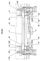
- the figure 1 represents an agricultural tractor TA equipped with a CH loader of known type, comprising a BR stretcher whose lifting and lowering movements are provided by a hydraulic cylinder VL said lifting cylinder.
- a tool holder frame 1 which is articulated at its base, its pivoting being provided by another hydraulic cylinder VB said tipping cylinder or digging cylinder.
- a set of connecting rods BC ensures the connection between the rod of this jack VB and the tool holder frame 1.
- This tool holder frame is provided in the upper part of a pair of hands MA , shaped gutters open upwards, intended to ensure its attachment to a tool 2, for example a bucket.
- This tool 2 has on its dorsal face means of attachment and retention which consist in particular of a pair of bars TA able to engage (by a movement from top to bottom) on hands MA ; in addition, FE fittings located on the back of the tool 2 have OV locking holes through which the locking pins carried by the tool holder frame 1 can pass, so as to ensure the attachment of the tool to this door frame -tool.
- the FE fittings have at their base a bearing zone ZA , in the form of a notch, able to bear against a crossbar BA extending transversely to the base of the frame 1.
- longitudinal direction will be referred to as the horizontal direction corresponding to the direction of travel of the tractor (located in the plane of the drawing sheet of the figure 1 ) and "transverse direction” the direction perpendicular to the longitudinal direction (perpendicular to the plane of the sheet).
- This tool holder frame 1 has a generally symmetrical configuration with respect to the median longitudinal vertical plane.
- the two flanges are fixed by welding at the ends of a pair of high and low crosspieces 6, which consist of cylindrical metal rods.
- X-X ' and Y-Y' respectively denote the axes of the crosspieces 5 and 6.
- the two flanges are connected to each other by a rod 30 located below the upper cross member 5, also horizontal axis and transverse W-W ' .
- the upper crossmember 5 has sleeve-like ends 50 which are fixed to the inner flanges 4.
- Each sleeve 50 is integral with a plate 51 which extends vertically upwards and has inclined chamfered edges 510, respectively 511, which give it the shape of a trapezium.
- lever 7 which is articulated at its base around the rod 30.
- lever 7 comprises an arched body 70 whose base is traversed by a transverse bore 71, which receives the hinge rod 30.
- the lever At its upper end, the lever carries a gutter 700, which is the attachment hand MA which has been mentioned above.
- the trough 700 is approximately the general shape of a "U" whose opening is directed upwards.
- the lever 7 is traversed by a transverse bore 72 in which can engage a rod 52, one end (facing to the right of the figure) carries a handle 53, while its other end is likely to engage, after passing through the bore 72 in a bore 500 provided in the sleeve 50.
- This sleeve therefore has a tubular shape.
- the length of the rod 52 is greater than the mutual spacing of the set of plates 3 and 4.
- Suitable means not shown, are provided to ensure the locking of this rod 52 in this dark position, shown on the figure 2 .
- the two rods 52 serve as hooking bars for a tool according to a second standard.
- the pivoting lever 7 is in an erect position so that its bore 72 is centered on the axis X-X ' , the introduction of the rod 52 in the bore 72 and in the drilling of the sleeve 50 a for effect to maintain the lever 7 and, correspondingly, the hand 700 in its erect position; it is an active position in which the hand 700 is adapted to receive a gripping bar which is provided with a tool complies with the first standard.
- a locking device 8 which, in a known manner, comprises an operating lever 81 adapted to provide displacements in axial translation, along an axis referenced Z-Z ' , of two locking rods. coaxial 80, via a set of rods 811.
- these displacements can be controlled by a hydraulic cylinder.
- the lever 81 is bent at the bottom; it is articulated about an axis 810 on a plate 62 which is carried by a stirrup 60, in the shape of a "U" returned, whose lateral branches are fixed, for example by welding, on the top of the bottom rail 6.
- the branches 61 have orifices which allow the passage and the guide of the locking rods 80; a light 600 provided in the upper horizontal leg of the stirrup 60 allows the passage and the movement of one of the links 811 and the lower part of the lever 81.
- the lateral pivoting of the control lever 81, around its hinge axis 810, ensures the simultaneous movement of the two rods 80 outwards (for locking) or inwards (for unlocking), in the direction of this pivoting.
- each of the inner plates 4 of the flange set 3-4 is mounted a support member 9; it affects the shape of a transverse horizontal axis roller (parallel to Y-Y ') carried by a small lever 90 hinged about an axis 900 at the base of the plate 4.
- the roller 9 extends between this lever 900 of arcuate shape, and a bearing element 91, also of arcuate shape.
- roller 9 By rotating the roller 9 about the axis 900, it can be brought to a low position, in which the elements 90 and 91 are in abutment against the crossbar 6, or in a raised position designated 9 '(retracted position shown in broken lines on the right of the figure 2 ).
- the plates 4 have a large central notch 40, directed forward (towards the tool to receive) which allows the movement of the member 9 in its pivoting movement.
- Suitable indexing and locking means are provided to maintain the support members 9 in their retracted high position.
- the figure 3 represents the dorsal surface of a tool belonging to a first standard, of the type marketed by MAILLEUX.
- the coupling elements of this tool on the tool holder frame essentially comprise a pair of vertical fittings 20a which run from the upper part to the lower part of the dorsal face of the body, to which they are welded, as well as a pair of legs 20'A, each located vis-à-vis the upper part of each fitting, at a distance from it, outwardly.
- each fitting 20A and the associated tab 20'A is fixed a bar 21 A of horizontal and transverse axis.
- the two bars 21A equipping the tool are located symmetrically on either side of a longitudinal central vertical axis and are arranged coaxially, that is to say in the extension of one another.
- the fittings 20A In their lower part, the fittings 20A have a locking orifice 22A and a notch 23A.
- the orifices 22A are also coaxial, as are the notches.
- the tool of figure 4 which conforms to a second standard, in this case the German standard designated "DGS" is also a body 2B, whose back face is provided with a pair of fittings 20B similar to those of the previously described tool 2A.
- DGS German standard
- fittings 20B are slightly closer to each other than the fittings 20A.
- a hook 21B On the outer side, at the upper part of each fitting, is fixed a hook 21B whose active part has the general shape of a beak "U" returned, forming a semi-cylindrical cavity.
- the fittings 20B have in the lower part a locking hole 22 B.
- these fittings have a flat edge 23B which acts as a bearing surface against the tool holder, as will be seen below.
- the 2C tool shown in figure 5 is a claw. It is a third standard compliant service tool on the Swedish market, designated "SMS”.
- the fittings provided on the back of these tools are vertical flat rods 20C which are provided in the upper part of a hook 21C having the shape of a spout whose opening, semi-cylindrical, is turned downwards.
- each fitting At the base of each fitting is provided a semi-cylindrical eyelet 22C. It has a transverse opening acting as a locking orifice.
- the operator on the agricultural tractor can manipulate the tool holder as he wishes, tilting it more or less with the tipping cylinder and lifting it more or less. , thanks to the lifting cylinder, to engage it against the dorsal surface of the tool, and to hook the tool.
- the levers 7 are raised and immobilized in their raised position, thanks to the rods 52, as explained above.
- Both hands 700 are thus in the active position.
- each hand 700 corresponds to the game close engagement
- the length of each bar 21 A corresponds, of course, to the mutual spacing of these bars.
- the width of the gutter that constitutes each hand 700 corresponds, with the interlocking clearance, to the diameter of a bar 2 1 A.
- this diameter is equal to 50 mm.
- the position of the rollers 9 relative to the hands 700 when these rollers are in their active position of the figure 6 is determined such that when the bars 21A are engaged in the hands 700, each roller bears in the notch 23A of a fitting.
- the position of the locking rods 80 is determined such that after latching and pressing the tool 2A on the tool holder 1, the locking holes 22A are each in the axial alignment Z-Z ' said rods 80.
- the rods 52 have a diameter which corresponds to the interlocking clearance, to the width of the openings of the hooks 21 B.
- this diameter is 40 mm.
- the orifices 22B are positioned opposite the locking rods 80 and the support edges 23B of the tool bear against the rollers 9.
- the levers 7 are retracted (in a position referenced 7 '); the rollers 9 are also retracted, by lifting, in a referenced position 9 '.
- this diameter is 60 mm.
- the locking holes 22B and 22C have a smaller diameter than the locking holes 22A of the tool 2A.
- these diameters are 20 mm for tools 2B and 2C and 30 mm for tool 2A.
- the locking rods 80 have a diameter adapted to engage directly in an orifice 22B or 22C. Their diameter is therefore slightly less than 20 mm.
- the rod 80 is integral at its end with a bar 83.
- the latter is traversed by a bore which is engaged on the end portion of the rod 80, a pin 830 ensuring the complete joining of the bar 83 with the rod 80 .
- the bar 83 extends perpendicular to the rod 80, substantially in a horizontal plane.
- the locking device also comprises an articulated lever 87, which can pivot in its central part around a vertical axis 88.
- This axis is carried by a plate referenced 63 on the figure 2 .
- this lever 87 is integral with a sleeve 800.
- a connecting rod 84 connects one end of the bar 83 with the other end of the lever 87.
- the rod 84 is directly articulated, via an axis 86, on the lever 87.
- This rod has a light 840 inside which engages a finger 85 integral with the bar 83.
- the sleeve 800 has a diameter d 2 greater than the diameter d 1 of the rod 80.
- the sleeve 800 is tubular; it has a cylindrical central opening 801 able to engage, with a certain clearance, on the end portion of the rod 80.
- Reference t indicates the trajectory of the center of the sleeve 800 during this pivoting; it is a trajectory in an arc of a circle, tangent to the axis of the rod 80.
- the opening 801 inside the sleeve 800 is bordered by a conical inlet surface 801 'constituting a flared mouthpiece which allows this engagement at the end of the pivoting stroke of the lever 87.
- the diameters d 1 and d 2 correspond, with the engagement clearance, to the diameters D 1 and D 2 corresponding, respectively, to the diameters of the locking holes of the tools according to the second and third standards, on the one hand (20 mm ), and the first standard, on the other hand (30 mm).
- the mutual spacing of the orifices 22C is slightly smaller than the mutual spacing of the orifices 22B, which itself is slightly smaller than the mutual spacing of the orifices 22A.
- the locking device is thus positioned and dimensioned so that the fittings 20B and 20C are positioned facing the end portion of the rods 80, between the bar 83 and the sleeve 800 (FIGS. figure 17 ).
- fitting 20A is positioned at the sleeve 800 ( figure 18 ).
- each fitting 20 being placed between the end of a rod 80 and the associated sleeve 800, after which the locking is carried out ( figure 17 or 18 ).
- the view of the figure 19 which refers to a tool according to the first standard, shows that, firstly, the bars 21A are engaged in the hands 700, and that the fittings 20A are at the sleeves 800, which ensure the locking.
- fittings 21B are opposite the rods 52, outside the sleeves 50 and the plates 51; it is also observed that the fittings 20B are opposite the portions 80 of the locking rods (which pass through them).
- the hooks 21C are in engagement with the portions of the sleeves 50 situated inward with respect to the plates 51; it is the internal inclined edges 511 of the plates 51 which ensure the guiding and centering of the tool relative to the tool holder frame during the approach phase, the hooks this time being placed inside the two pads 51.
- the locking holes 22C are positioned relative to the rods 80, which pass through them, in a position slightly inwardly offset with respect to the position occupied by the orifices 22B.
- a tool holder frame according to the invention although originally designed to equip an agricultural tractor can also find applications in other areas, in particular for equipping public works machinery, for earthworks for example.
Abstract
Description
La présente invention concerne un cadre porte-outil à caractère polyvalent destiné à équiper un chargeur, notamment un chargeur frontal à usage agricole monté sur un tracteur.The present invention relates to a versatile toolholder frame intended to equip a loader, including a front loader for agricultural use mounted on a tractor.
Un tel chargeur, à commande hydraulique, est conçu pour pouvoir manipuler des matériaux divers dans une exploitation agricole, tels que de la paille, du foin, du fumier, de la terre, des engrais, des céréales, des betteraves, des pommes de terre, de l'ensilage, notamment.Such a hydraulically operated loader is designed to handle various materials on a farm, such as straw, hay, manure, soil, fertilizer, cereals, beets, potatoes , silage, in particular.
A cet effet, l'exploitant doit avoir à disposition divers outils amovibles, adaptés chacun à des travaux et/ou des matériaux spécifiques.To this end, the operator must have available various removable tools, each adapted to specific work and / or materials.
Ces outils sont en particulier des bennes, des griffes, des grappins, des lames, des fourches, des transpalettes, ou des outils combinés, tels que des bennes à griffes par exemple.These tools are in particular skips, claws, grapples, blades, forks, pallet trucks, or combined tools, such as clamshells, for example.
Le cadre porte-outil fixé au bout des bras du chargeur et la face dorsale de l'outil (face tournée vers le chargeur) possèdent des moyens d'accouplement complémentaires dont la conception permet le changement rapide de l'outil.The tool holder frame attached to the end of the loader arms and the back face of the tool (face facing the loader) have complementary coupling means whose design allows the rapid change of the tool.
Une difficulté rencontrée par les constructeurs et leurs clients utilisateurs réside dans le fait qu'il n'y a pas de normalisation en la matière, de sorte qu'un outil provenant d'un constructeur donné n'est pas forcément adaptable sur un ensemble chargeur/cadre porte-outil provenant de chez un autre constructeur.A difficulty encountered by manufacturers and their user customers lies in the fact that there is no standardization in the field, so that a tool from a given manufacturer is not necessarily adaptable on a loader assembly / tool holder frame from another manufacturer.
Le choix d'un usager souhaitant s'équiper en nouveaux outils se trouve par conséquent limité dans la mesure où il ne peut acheter que des modèles adaptables sur le chargeur qu'il a en sa possession.The choice of a user wishing to equip himself with new tools is therefore limited insofar as he can only buy adaptable models on the charger he has in his possession.
Inversement, s'il souhaite changer de chargeur, il peut être dissuadé, pour des raisons pécuniaires, d'acheter un modèle sur lequel il ne pourra pas adapter les outils préalablement achetés, dont il dispose.Conversely, if he wants to change charger, he can be dissuaded, for pecuniary reasons, to buy a model on which he can not adapt the previously purchased tools, which he has.
En pratique, il existe en Europe trois grandes catégories de systèmes d'accouplement, correspondant à des standards de fait.In practice, there are three main categories of coupling systems in Europe, corresponding to de facto standards.
Un premier standard, commercialisé sous la marque "MAILLEUX", est caractérisé en ce que le cadre porte-outil comporte une paire de mains d'accrochage identiques de section approximativement en "U", dont l'ouverture est dirigée vers le haut, disposées coaxialement et symétriquement de part et d'autre du plan vertical et longitudinal médian du cadre porte-outil, tandis que la face dorsale de l'outil est pourvue, en partie haute, d'une paire de barreaux coaxiaux, ainsi dimensionnés et positionnés que chacun d'eux peut s'emboîter et se loger à l'intérieur d'une main d'accrochage. Chaque barreau est monté entre deux ferrures, dont l'une se prolonge vers le bas, et présente un orifice de verrouillage et une encoche. Le cadre porte-outil est équipé d'un dispositif de verrouillage comprenant une paire de broches mobiles en translation, aptes à venir s'insérer chacune dans l'un de ces orifices, et assurer la fixation de l'outil sur le cadre porte-outil. L'encoche sert de zone d'appui de la partie basse de l'outil contre des butées appropriées dont est muni le cadre porte-outil.A first standard, marketed under the trademark "MAILLEUX", is characterized in that the tool holder frame comprises a pair of identical hooking hands of approximately "U" -shaped section, whose opening is directed upwards, arranged coaxially and symmetrically on both sides of the vertical and longitudinal median plane of the tool frame, while the dorsal surface of the tool is provided, at the top, with a pair of bars coaxial, so dimensioned and positioned that each of them can fit and be housed inside a gripping hand. Each bar is mounted between two fittings, one of which extends downwards, and has a locking hole and a notch. The tool-holder frame is equipped with a locking device comprising a pair of pins movable in translation, each adapted to fit into one of these orifices, and ensuring the attachment of the tool to the frame-holder tool. The notch serves as a bearing area of the lower part of the tool against appropriate stops which is provided with the tool holder frame.
Selon les modèles, le dispositif de verrouillage est commandé manuellement, à l'aide d'un levier de manoeuvre, ou hydrauliquement, au moyen d'un vérin, comme cela est décrit par exemple dans le document
Un deuxième standard, notamment usité sur le marché allemand, et communément désigné "DGS", est caractérisé en ce que le cadre porte-outil comporte une paire de barreaux d'accrochage coaxiaux disposés symétriquement de part et d'autre du plan vertical et longitudinal médian du cadre porte-outil, tandis que la face dorsale est pourvue, en partie haute, d'une paire de crochets coaxiaux, dont l'ouverture est dirigée vers le bas, ainsi dimensionnés et positionnés que chacun d'eux peut s'engager sur un barreau d'accrochage, et l'emprisonner.A second standard, particularly used on the German market, and commonly referred to as "DGS", is characterized in that the tool holder frame comprises a pair of coaxial hooking bars arranged symmetrically on either side of the vertical and longitudinal plane. middle of the tool holder frame, while the dorsal surface is provided, in the upper part, a pair of coaxial hooks, whose opening is directed downwards, so dimensioned and positioned that each of them can engage on a hanging bar, and imprison him.
Comme pour le premier standard, la face dorsale de l'outil comporte une paire de ferrures présentant un orifice de verrouillage, et une zone d'appui pour sa partie basse.As for the first standard, the back face of the tool comprises a pair of fittings having a locking hole, and a support zone for its lower part.
Il y a en quelque sorte une inversion des organes d'accrochage, les organes "mâles" (barreaux) étant portés par l'outil dans le premier standard, et par le cadre porte-outil dans le deuxième standard, tandis que les organes "femelles" (mains ou crochets) sont portés par le cadre porte-outil dans le premier standard, et par l'outil dans le deuxième standard.There is somehow an inversion of the attachment members, the "male" members (bars) being carried by the tool in the first standard, and the tool holder in the second standard, while the organs " females "(hands or hooks) are carried by the tool holder in the first standard, and by the tool in the second standard.
De plus, les orifices de verrouillage, et corrélativement les broches qui y pénètrent, ont des diamètres différents; le diamètre de ces orifices est de 30 mm pour le premier standard et de 20 mm pour le deuxième.In addition, the locking holes, and correlatively the pins that penetrate, have different diameters; the diameter of these orifices is 30 mm for the first standard and 20 mm for the second.
Un troisième standard, notamment usité sur le marché suédois, et communément désigné "SMS", a une structure globalement similaire à celle du deuxième standard, les barreaux étant portés par le cadre porte-outil, et les crochets par l'outil. Toutefois, chacun des orifices de verrouillage est constitué non pas par un alésage percé dans une ferrure, mais par un oeillet fixé à la base d'une tige plate dont la partie supérieure porte un crochet. Selon ce troisième standard, chaque crochet se trouve donc dans le même plan vertical et longitudinal qu'un orifice de verrouillage, alors que selon les deux premiers standards, les moyens d'accrochage (barreaux ou crochets) sont décalés latéralement, vers l'extérieur, par rapport aux ferrures dans lesquelles sont percés les orifices de verrouillage.A third standard, particularly used on the Swedish market, and commonly referred to as "SMS", has a structure similar to that of the second standard, the bars being carried by the tool holder frame, and the hooks by the tool. However, each of the locking holes is constituted not by a bore drilled in a fitting, but by an eyelet fixed to the base of a flat rod whose upper part carries a hook. According to this third standard, each hook is therefore in the same vertical and longitudinal plane as an orifice of locking, while according to the first two standards, the hooking means (bars or hooks) are offset laterally outwardly relative to the fittings in which are drilled the locking holes.
En outre, les crochets des second et troisièmes standards, tous deux en forme de "U" renversé, ont des largeurs différentes; corrélativement, les barreaux d'accrochage ont des diamètres différents, de valeur 40 mm pour le second standard, et 60 mm pour le troisième.In addition, the hooks of the second and third standards, both U-shaped overturned, have different widths; correspondingly, the fastening bars have different diameters, of
Les barreaux d'accrochage du premier standard ont, quant à eux, un diamètre ayant une valeur de 50 mm.The snap bars of the first standard have, for their part, a diameter having a value of 50 mm.
Par ailleurs, les valeurs des écartements mutuels -ou entraxes- des organes de fixation et des orifices de verrouillage d'une même paire sont différentes pour chacun de ces trois standards.Furthermore, the values of the mutual spacings - or center distances - of fasteners and locking holes of the same pair are different for each of these three standards.
La présente invention a pour but de résoudre ces problèmes d'incompatibilité en proposant un cadre porte-outil capable d'être accouplé à un outil conforme au premier standard précité, et au moins à l'un des deux autres, ce cadre porte-outil étant néanmoins de conception relativement simple, d'un prix de revient acceptable, et commode d'utilisation.The object of the present invention is to solve these incompatibility problems by proposing a tool-holder frame capable of being coupled to a tool conforming to the aforementioned first standard, and at least to one of the other two, this tool-holder frame. nevertheless being of relatively simple design, an acceptable cost price, and convenient to use.
L'invention concerne donc un cadre porte-outil pour chargeur, notamment à usage agricole, qui comporte une paire de mains d'accrochage identiques en forme de tronçon de gouttière de section approximativement en forme de "U" dont l'ouverture est dirigée vers le haut, les deux mains étant disposées symétriquement de part et d'autre du plan vertical et longitudinal médian du cadre porte-outil, coaxialement suivant un axe horizontal transversal, ce cadre porte-outil étant destiné à être accouplé à un outil satisfaisant à un standard de montage donné, dit "premier standard", dont la face dorsale est pourvue, en partie haute, d'une paire de barreaux coaxiaux, ainsi dimensionnés et positionnés que chacun d'eux peut s'emboîter et se loger à l'intérieur d'une main d'accrochage, de telle sorte que l'outil conforme au premier standard se trouve alors convenablement supporté par le cadre porte-outil.The invention therefore relates to a toolholder frame for a loader, particularly for agricultural use, which comprises a pair of identical hooking hands in the form of a gutter section of approximately U-shaped section whose opening is directed towards the top, the two hands being arranged symmetrically on either side of the vertical and longitudinal median plane of the tool holder frame, coaxially along a transverse horizontal axis, this tool holder being intended to be coupled to a tool satisfying a given standard of assembly, said "first standard", whose dorsal face is provided, in the upper part, with a pair of coaxial bars, so dimensioned and positioned that each of them can fit and lodge inside of a gripping hand, so that the tool complies with the first standard is then properly supported by the tool holder frame.
Conformément à l'invention, le cadre porte-outil comporte, en outre, au moins une paire de barreaux d'accrochage coaxiaux disposés symétriquement de part et d'autre du plan vertical et longitudinal médian du cadre porte-outil, qui autorisent l'accouplement de ce dernier à un outil satisfaisant à au moins un autre standard de montage, dit "deuxième standard", dont la face dorsale est pourvue, en partie haute, d'une paire de crochets coaxiaux, dont l'ouverture est dirigée vers le bas, ainsi dimensionnés et positionnés que chacun d'eux peut s'engager sur un barreau d'accrochage, et l'emprisonner, de telle sorte que l'outil conforme au deuxième standard se trouve alors convenablement supporté par le cadre porte-outilAccording to the invention, the tool holder frame further comprises at least one pair of coaxial hooking bars arranged symmetrically on both sides of the vertical and longitudinal median plane of the tool holder frame, which allow the coupling of the latter to a tool satisfying at least one other mounting standard, called "second standard", whose dorsal face is provided, in the upper part, a pair of coaxial hooks, the opening is directed towards the down, so sized and positioned that each of them can engage on a hooking bar, and to trap it, so that the tool conforming to the second standard is then properly supported by the tool-holder frame
Selon d'autres caractéristiques avantageuses, mais non limitatives de l'invention :
- chacune desdites mains d'accrochage est portée par un levier articulé susceptible d'occuper sélectivement, par pivotement, soit une position dressée active, dans laquelle elle est capable d'accueillir et de supporter un barreau solidaire d'un outil conforme au premier standard, soit une position basse inactive dans laquelle elle est escamotée de telle sorte qu'elle ne contrarie pas l'accouplement du cadre porte-outil avec un outil conforme au deuxième standard, et notamment l'engagement des crochets dont est pourvu cet outil sur lesdits barreaux d'accrochage;
- le cadre porte-outil comprend une armature comprenant des traverses horizontales haute et basse reliées, à chacune de leurs extrémités, par une paire de plaques parallèles s'étendant sensiblement dans des plans verticaux longitudinaux et formant un jeu de flasques entre lesquels est monté le levier articulé;
- chacun desdits leviers présente une ouverture transversale susceptible d'être traversée par une tige cylindrique amovible, portée par l'un desdits jeux de flasques, cette tige étant adaptée pour assurer sélectivement l'une des deux fonctions suivantes:
- maintenir le levier en position dressée active, lorsqu'elle est insérée dans ladite ouverture;
- faire office de barreau d'accrochage apte à coopérer avec le crochet d'un outil conforme au deuxième standard, lorsqu'elle n'est pas insérée dans ladite ouverture, et que le levier est escamoté dans sa position basse inactive;
- les portions d'extrémité de ladite traverse haute sont fixées aux flasques intérieurs desdits jeux de flasques et elles sont tubulaires, leur diamètre interne étant ainsi dimensionné qu'il autorise l'engagement et le centrage d'une portion d'extrémité de ladite tige amovible, lorsqu'elle est insérée dans le jeu de flasques.
- le cadre porte-outil comporte deux paires distinctes de barreaux d'accrochage, de diamètres différents, et dont l'écartement mutuel en direction transversale est différent, l'une des paires de barreaux étant adaptée pour coopérer avec une paire de crochets solidaires d'un outil conforme au deuxième standard, et l'autre avec une paire de crochets solidaires d'un outil conforme à un troisième standard;
- les portions d'extrémité de la traverse haute sont des manchons cylindriques accolés aux flasques intérieurs, qui ont un diamètre externe supérieur à celui desdites tiges amovibles, et sont adaptés pour faire office de barreaux d'accrochage aptes à coopérer avec les crochets d'un outil conforme au troisième standard;
- chacun desdits manchons cylindriques est solidaire d'une plaquette présentant des bords biseautés, cette plaquette étant adaptée pour faciliter le guidage relatif du cadre porte-outil et de l'outil conforme au deuxième ou au troisième standard lors de la phase d'approche en vue de leur accouplement, et pour assurer leur bon centrage mutuel après accouplement;
- le cadre porte-outil comporte, en partie inférieure, une paire d'organes d'appui escamotables, situés au voisinage des extrémités de ladite traverse inférieure, chacun d'eux étant susceptible d'occuper sélectivement soit une position saillante et active, dans laquelle elle vient en appui contre des ferrures solidaires de la face dorsale de l'outil, lorsque ce dernier est accouplé au cadre porte-outil, soit une position escamotée et inactive, dans laquelle c'est la traverse inférieure qui assure cet appui, directement contre la zone inférieure de la face dorsale de l'outil;
- lesdits organes d'appui sont des rouleaux horizontaux, d'axe transversal, portés par un levier qui est articulé autour d'un axe porté par l'un des flasques intérieurs, leur escamotage étant réalisé par relèvement de ces leviers, tandis que leur déplacement en position active se fait par pivotement desdits leviers vers le bas, ladite traverse basse faisant alors office de butée pour les organes d'appui;
- le cadre porte-outil comporte des organes de verrouillage de l'outil sur le cadre porte-outil, qui sont adaptés pour pénétrer aussi bien dans des orifices de verrouillage prévus sur des ferrures solidaires d'un outil conforme au premier standard, que dans des orifices de verrouillage, de diamètre différent, prévus sur des ferrures solidaires d'un outil conforme au deuxième et/ou au troisième standard.
- each of said gripping hands is carried by an articulated lever capable of selectively occupying, by pivoting, or an active erect position, in which it is able to receive and support a bar secured to a tool according to the first standard, an inactive low position in which it is retracted in such a way that it does not interfere with the coupling of the tool-holder frame with a tool conforming to the second standard, and in particular the engagement of the hooks of which this tool is provided on said bars hooking;
- the tool holder frame comprises an armature comprising horizontal high and low cross members connected at each of their ends by a pair of parallel plates extending substantially in longitudinal vertical planes and forming a set of flanges between which is mounted the lever Speak clearly;
- each of said levers has a transverse opening capable of being traversed by a removable cylindrical rod, carried by one of said sets of flanges, this rod being adapted to selectively perform one of the following two functions:
- maintain the lever in active up position, when inserted into said opening;
- acting hooking bar adapted to cooperate with the hook of a tool according to the second standard, when not inserted into said opening, and that the lever is retracted into its inactive low position;
- the end portions of said upper cross member are fixed to the inner flanges of said flange sets and they are tubular, their inner diameter being so dimensioned as to allow engagement and centering of an end portion of said removable rod; when inserted into the flange game.
- the tool holder frame comprises two distinct pairs of hooking bars, of different diameters, and whose mutual spacing in the transverse direction is different, one of the pairs of bars being adapted to cooperate with a pair of integral hooks of a tool conforming to the second standard, and the other with a pair of hooks integral with a tool according to a third standard;
- the end portions of the upper cross member are cylindrical sleeves contiguous to the inner flanges, which have an external diameter greater than that of said removable rods, and are adapted to serve as hooking bars adapted to cooperate with the hooks of a tool conforming to the third standard;
- each of said cylindrical sleeves is integral with a wafer having beveled edges, this wafer being adapted to facilitate the relative guidance of the tool holder frame and the tool according to the second or third standard during the approach phase in view their coupling, and to ensure proper mutual centering after mating;
- the tool holder frame comprises, in the lower part, a pair of retractable support members, located in the vicinity of the ends of said bottom rail, each of them being capable of selectively occupying either a projecting and active position, in which it bears against integral hardware of the dorsal face of the tool, when the latter is coupled to the tool holder frame, a retracted and inactive position, in which it is the lower rail that provides this support, directly against the lower zone of the dorsal face of the tool;
- said support members are horizontal rollers, transverse axis, carried by a lever which is articulated about an axis carried by one of the inner flanges, their retraction being carried out by raising these levers, while their displacement in the active position is by pivoting said levers downwards, said lower crossbar then acting as a stop for the support members;
- the tool-holder frame comprises tool-locking members on the tool-holder frame, which are adapted to penetrate both into locking holes provided on integral fittings of a tool according to the first standard, as well as in locking holes, of different diameter, provided on integral fittings of a tool according to the second and / or third standard.
D'autres caractéristiques et avantages de l'invention apparaîtront à la lecture de la description suivante d'un mode de réalisation préféré de l'invention. Cette description est faite en référence aux dessins annexés dans lesquels :
- la
figure 1 est une vue générale, de côté, d'un tracteur agricole équipé d'un chargeur portant un cadre porte-outil ; cette figure montre également un outil, en l'occurrence une benne, apte à être accouplée au cadre porte-outil ; - la
figure 2 est une vue générale, en perspective, avec des éléments vus en détail en vue éclatée, qui représente schématiquement un cadre porte-outil conforme à l'invention ; - les
figures 3 à 5 représentent, vus de trois-quarts arrière, trois outils de catégories différentes susceptibles d'être accouplés au cadre porte-outil conforme à l'invention, ces outils étant conformes respectivement à un premier, un deuxième, et un troisième standard ; - les
figures 6, 7 et 8 sont des vues en perspective du cadre porte-outil, dans des configurations d'utilisation destinées à coopérer respectivement avec un outil conforme au premier, au deuxième et au troisième standard; - les
figures 9, 10 et 11 sont des vues de côté d'un outil conforme respectivement au premier, au deuxième et au troisième standard ; - les
figures 12, 13 et 14 sont des vues de côté du cadre porte-outil dans une configuration qui correspond à son accouplement avec respectivement l'outil de lafigure 9 , l'outil de lafigure 10 et l'outil de lafigure 11 ; - la
figure 15 est une vue de détail qui représente un système de verrouillage équipant le cadre porte-outil de l'invention, ce système étant adapté pour pouvoir coopérer avec des orifices de verrouillage de diamètre différent, ledit système étant représenté dans sa position ouverte, de déverrouillage ; - la
figure 16 est une vue similaire à celle de lafigure 15 qui représente le système en position de verrouillage ; - les
figures 17 et 18 sont des vues analogues à celle de lafigure 16 , à échelle plus petite, qui représentent des verrouillages dans des orifices de diamètre différent ; - les
figures 19 ,20 et21 sont des vues schématiques partielles, de dessus, illustrant la manière dont le cadre porte-outil est accouplé, respectivement, à un outil conforme au premier, au deuxième, et au troisième standard ; - les
figures 22, 23 et 24 sont des vues de face de la partie arrière d'outils conformes respectivement au premier, au deuxième, et au troisième standard, ces vues étant essentiellement destinées à préciser les différentes côtes des organes d'accrochage et de retenue des outils sur le cadre porte-outil.
- the
figure 1 is a general view, from the side, of an agricultural tractor equipped with a loader carrying a tool-holder frame; this figure also shows a tool, in this case a bucket, adapted to be coupled to the tool holder frame; - the
figure 2 is a general view, in perspective, with elements seen in detail in exploded view, which shows schematically a tool holder frame according to the invention; - the
Figures 3 to 5 represent, seen three-quarter rear, three tools of different categories may be coupled to the tool holder frame according to the invention, these tools being respectively compliant with a first, a second, and a third standard; - the
Figures 6, 7 and 8 are perspective views of the tool holder frame, in use configurations for cooperating respectively with a tool according to the first, second and third standard; - the
Figures 9, 10 and 11 are side views of a tool in accordance with the first, second and third standards respectively; - the
Figures 12, 13 and 14 are side views of the tool holder frame in a configuration which corresponds to its coupling with the tool of thefigure 9 , the tool of thefigure 10 and the tool of thefigure 11 ; - the
figure 15 is a detail view which represents a locking system equipping the tool holder frame of the invention, this system being adapted to cooperate with locking holes of different diameter, said system being shown in its open position, unlocking; - the
figure 16 is a view similar to that of thefigure 15 which represents the system in the locking position; - the
Figures 17 and 18 are views similar to that of thefigure 16 on a smaller scale, which represent interlocks in holes of different diameters; - the
figures 19 ,20 and21 are partial diagrammatic views, from above, illustrating the manner in which the tool-holder frame is coupled, respectively, to a tool conforming to the first, second and third standards; - the
Figures 22, 23 and 24 are front views of the rear part of tools respectively compliant with the first, second and third standards, these views being essentially intended to specify the different sides of the attachment and retaining means of the tools on the support frame. tool.
La
A l'extrémité libre du brancard BR est monté un cadre porte-outil 1 qui est articulé à sa base, son pivotement étant assuré par un autre vérin hydraulique VB dit vérin de bennage ou vérin de cavage.At the free end of the BR stretcher is mounted a
Toujours de manière connue, un jeu de biellettes BC assure la liaison entre la tige de ce vérin VB et le cadre porte-outil 1.Still in a known manner, a set of connecting rods BC ensures the connection between the rod of this jack VB and the
Ce cadre porte-outil est pourvu en partie haute d'une paire de mains MA, en forme de gouttières ouvertes vers le haut, destinées à assurer son accrochage sur un outil 2, par exemple une benne.This tool holder frame is provided in the upper part of a pair of hands MA , shaped gutters open upwards, intended to ensure its attachment to a tool 2, for example a bucket.
Cet outil 2 comporte sur sa face dorsale des moyens d'accrochage et de retenue qui consistent notamment en une paire de barreaux TA aptes à s'engager (par un mouvement du haut vers le bas) sur les mains MA ; de plus, des ferrures FE situées au dos de l'outil 2 présentent des orifices de verrouillage OV pouvant être traversés des broches de verrouillage portées par le cadre porte-outil 1, de manière à assurer la solidarisation de l'outil sur ce cadre porte-outil.This tool 2 has on its dorsal face means of attachment and retention which consist in particular of a pair of bars TA able to engage (by a movement from top to bottom) on hands MA ; in addition, FE fittings located on the back of the tool 2 have OV locking holes through which the locking pins carried by the
On notera également que les ferrures FE présentent à leur base une zone d'appui ZA, en forme d'encoche, apte à venir prendre appui contre une traverse BA s'étendant transversalement à la base du cadre 1.It will also be noted that the FE fittings have at their base a bearing zone ZA , in the form of a notch, able to bear against a crossbar BA extending transversely to the base of the
Dans la suite de la description, et dans les revendications, on désignera par "direction longitudinale" la direction horizontale correspondant à la direction d'avance du tracteur (située dans le plan de la feuille de dessin de la
En référence à la
Ce cadre porte-outil 1a une configuration généralement symétrique par rapport à plan vertical longitudinal médian.This
Il comprend à ses extrémités latérales une paire de plaques métalliques 3, 4 reliées les unes aux autres par des entretoises appropriées de manière à constituer une paire de flasques solidaires l'un de l'autre.It comprises at its lateral ends a pair of
Les deux flasques sont fixés par soudage aux extrémités d'une paire de traverses haute 5 et basse 6, lesquelles sont constituées par des tiges cylindriques métalliques.The two flanges are fixed by welding at the ends of a pair of high and
On a désigné par les références X-X' et Y-Y', respectivement, les axes des traverses 5 et 6. X-X ' and Y-Y' respectively denote the axes of the
Par ailleurs, les deux flasques sont reliés l'un à l'autre par une tige 30 située en dessous de la traverse supérieure 5, d'axe également horizontal et transversal W-W'.Furthermore, the two flanges are connected to each other by a
La traverse supérieure 5 possède des extrémités en forme de manchons 50 qui sont fixés aux flasques intérieurs 4.The
Chaque manchon 50 est solidaire d'une plaquette 51 qui s'étend verticalement vers le haut et possède des chants chanfreinés inclinés 510, respectivement 511, qui lui confèrent la forme d'un trapèze.Each
Entre chacun des jeux de flasques 3-4 est disposé un levier 7 qui est articulé à sa base autour de la tige 30.Between each of the sets of flanges 3-4 is a
Sur la vue de la
Un levier identique, prévu sur la partie gauche du dessin, n'est pas représenté.An identical lever, provided on the left side of the drawing, is not shown.
La vue de détail éclatée qui est détachée de la figure, permet de constater que le levier 7 comprend un corps arqué 70 dont la base est traversée par un alésage transversal 71, lequel reçoit la tige d'articulation 30.The exploded detail view which is detached from the figure, allows to note that the
A son extrémité supérieure, le levier porte une gouttière 700, qui constitue la main d'accrochage MA dont il a été fait état plus haut.At its upper end, the lever carries a
La gouttière 700 a approximativement la forme générale d'un "U" dont l'ouverture est dirigée vers le haut.The
En partie haute, le levier 7 est traversé par un alésage transversal 72 dans lequel peut s'engager une tige 52 dont une extrémité (tournée vers la droite de la figure) porte une manette de préhension 53, tandis que son autre extrémité est susceptible de s'engager, après avoir traversé l'alésage 72 dans un perçage 500 prévu dans le manchon 50.In the upper part, the
Ce manchon a par conséquent une forme tubulaire.This sleeve therefore has a tubular shape.
Bien entendu, la longueur de la tige 52 est supérieure à l'écartement mutuel du jeu de plaques 3 et 4.Of course, the length of the
Comme on le comprend aisément à la simple observation de la
Des moyens appropriés non représentés, sont prévus pour assurer le blocage de cette tige 52 dans cette position en foncée, représentée sur la
Comme on le verra plus tard, dans ce cas, les deux tiges 52 servent de barreaux d'accrochage pour un outil conforme à un second standard.As will be seen later, in this case, the two
Si au contraire, le levier pivotant 7 se trouve dans une position dressée de telle sorte que son alésage 72 se trouve centré sur l'axe X-X', l'introduction de la tige 52 dans cet alésage 72 puis dans le perçage du manchon 50 a pour effet d'assurer le maintien du levier 7 et, corrélativement, de la main 700 dans sa position dressée ; il s'agit d'une position active dans laquelle la main 700 est adaptée pour recevoir un barreau d'accrochage dont est pourvu un outil conforme au premier standard.If on the contrary, the pivoting
A la partie inférieure du cadre porte-outil 1 est installé un dispositif de verrouillage 8 qui, de manière connue, comprend un levier de manoeuvre 81 adapté pour assurer les déplacements en translation axiale, suivant un axe référencé Z-Z', de deux tiges de verrouillage coaxiales 80, via un jeu de biellettes 811.At the lower part of the
Dans un autre mode de réalisation possible de l'invention, ces déplacements peuvent être commandés par un vérin hydraulique.In another possible embodiment of the invention, these displacements can be controlled by a hydraulic cylinder.
Le levier 81 est coudé en partie inférieure ; il est articulé autour d'un axe 810 sur une plaque 62 qui est portée par un étrier 60, en forme de "U" retourné, dont les branches latérales sont fixées, par exemple par soudage, sur le dessus de la traverse basse 6.The
Les branches 61 présentent des orifices qui permettent le passage et le guidage des tiges de verrouillage 80 ; une lumière 600 prévue dans la branche horizontale supérieure de l'étrier 60 autorise le passage et le débattement de l'une des biellettes 811 et de la partie inférieure du levier 81.The
Le pivotement latéral du levier de commande 81, autour de son axe d'articulation 810, assure le déplacement simultané des deux tiges 80 vers l'extérieur (pour le verrouillage) ou vers l'intérieur (pour le déverrouillage), selon le sens de ce pivotement.The lateral pivoting of the
Par ailleurs, à la base de chacune des plaques intérieures 4 du jeu de flasques 3-4, est monté un organe d'appui 9 ; celui-ci affecte la forme d'un rouleau d'axe transversal horizontal (parallèle à Y-Y') porté par un petit levier 90 articulé autour d'un axe 900 à la base de la plaque 4.Furthermore, at the base of each of the
Le rouleau 9 s'étend entre ce levier 900 de forme arquée, et un élément d'appui 91, également de forme arquée.The
En faisant pivoter le rouleau 9 autour de l'axe 900, on peut l'amener soit dans une position basse, dans laquelle les éléments 90 et 91 sont en appui contre la traverse 6, soit dans une position relevée désignée 9' (position escamotée illustrée en traits interrompus sur la droite de la
Les plaques 4 présentent une large échancrure centrale 40, dirigée vers l'avant (vers l'outil à recevoir) qui autorise le débattement de l'organe 9 dans son mouvement de pivotement.The
Des moyens d'indexage et de blocage appropriés, non représentés, sont prévus pour assurer le maintien des organes d'appui 9 dans leur position haute escamotée.Suitable indexing and locking means, not shown, are provided to maintain the
Des moyens similaires peuvent être prévus pour assurer le maintien des leviers 7 dans leur position basse escamotée, entre les paires de flasques 3 et 4.Similar means may be provided to maintain the
On notera sur la
En effet, ce dispositif n'a pas été représenté sur la
En nous référant maintenant aux
La
Dans l'exemple illustré, il s'agit d'une benne ; il est bien entendu que des outils autres que des bennes, conformes à ce premier standard portent des moyens d'accouplement identiques à ceux de cette benne.In the illustrated example, it is a bucket; it is understood that tools other than buckets, in accordance with this first standard carry coupling means identical to those of this bucket.
Les éléments d'accouplement de cet outil sur le cadre porte-outil comprennent essentiellement une paire de ferrures verticales 20a qui courent de la partie supérieure à la partie inférieure de la face dorsale de la benne, à laquelle elles sont soudées, ainsi qu'une paire de pattes 20'A, situées chacune en vis-à-vis de la partie haute de chaque ferrure, à une certaine distance de celle-ci, vers l'extérieur.The coupling elements of this tool on the tool holder frame essentially comprise a pair of vertical fittings 20a which run from the upper part to the lower part of the dorsal face of the body, to which they are welded, as well as a pair of legs 20'A, each located vis-à-vis the upper part of each fitting, at a distance from it, outwardly.
Entre la partie supérieure de chaque ferrure 20A et la patte 20'A associée est fixé un barreau 21 A d'axe horizontal et transversal.Between the upper part of each fitting 20A and the associated tab 20'A is fixed a
Les deux barreaux 21A équipant l'outil sont situés symétriquement de part et d'autre d'un axe vertical longitudinal médian et sont disposés coaxialement, c'est-à-dire dans le prolongement l'un de l'autre.The two
Dans leur partie basse, les ferrures 20A présentent un orifice de verrouillage 22A et une encoche 23A.In their lower part, the
Les orifices 22A sont également coaxiaux, de même que les encoches.The
L'outil de la
Toutefois, les ferrures 20B sont légèrement plus rapprochées l'une de l'autre que les ferrures 20A. Du côté extérieur, au niveau de la partie haute de chaque ferrure, est fixé un crochet 21B dont la partie active a la forme générale d'un bec en"U" retourné, formant une cavité semi-cylindrique.However, the
Comme pour l'outil 2A, les ferrures 20B présentent en partie inférieure un orifice de verrouillage 22 B.As for the
Au lieu d'une encoche, ces ferrures présentent un chant plat 23B qui fait office de surface d'appui contre le porte-outil, comme on le verra plus loin.Instead of a notch, these fittings have a
L'outil 2C illustré à la
Les ferrures prévues au dos de ces outils sont des tiges plates verticales 20C qui sont pourvues en partie haute d'un crochet 21C ayant la forme d'un bec dont l'ouverture, semi-cylindrique, est tournée vers le bas.The fittings provided on the back of these tools are vertical
A la base de chaque ferrure est prévu un oeillet semi-cylindrique 22C. Il présente une ouverture transversale faisant office d'orifice de verrouillage.At the base of each fitting is provided a
En référence à la
Il va de soi que, de manière connue, l'opérateur qui se trouve sur le tracteur agricole peut manipuler à sa guise le cadre porte-outil, en l'inclinant plus ou moins grâce au vérin de bennage et en le soulevant plus ou moins, grâce au vérin de levage, pour l'engager contre la face dorsale de l'outil, et pour accrocher l'outil.It goes without saying that, in a known manner, the operator on the agricultural tractor can manipulate the tool holder as he wishes, tilting it more or less with the tipping cylinder and lifting it more or less. , thanks to the lifting cylinder, to engage it against the dorsal surface of the tool, and to hook the tool.
Afin de pouvoir accoupler le cadre porte-outil à un outil conforme au premier standard, on relève les leviers 7 et on les immobilise dans leur position relevée, grâce aux tiges 52, comme cela a été expliqué plus haut.In order to be able to couple the tool frame to a tool according to the first standard, the
Les deux mains 700 se trouvent ainsi en position active.Both
Par ailleurs, on abaisse les rouleaux d'appui 9 de telle sorte qu'ils se trouvent en butée contre la traverse 6.Furthermore, the
C'est cette configuration du cadre porte-outil qui est représenté sur la
De même, la largeur de la gouttière que constitue chaque main 700 correspond, au jeu d'emboîtement près, au diamètre d'un barreau 2 1 A.Likewise, the width of the gutter that constitutes each
En pratique, ce diamètre est égal à 50 mm.In practice, this diameter is equal to 50 mm.
La position des rouleaux 9 par rapport aux mains 700 lorsque ces rouleaux se trouvent dans leur position active de la
De même, la position des tiges de verrouillage 80 est déterminée de telle sorte qu'après accrochage et mise en appui de l'outil 2A sur le porte-outil 1, les orifices de verrouillage 22A se trouvent chacun dans l'alignement axial Z-Z' desdites tiges 80.Similarly, the position of the locking
En référence à la
On constate que les leviers 7 ont été escamotés, en position basse référencée 7'.It can be seen that the
En revanche, les organes d'appui 9 ont été maintenus en position saillante active, comme dans la configuration précédente.On the other hand, the
Dans cette configuration, ce sont les tiges 52, faisant alors office d'organe d'accrochage, qui sont adaptées pour s'engager dans les crochets 21B, l'écartement mutuel des tiges 52 étant naturellement déterminé en conséquence.In this configuration, it is the
Les tiges 52 ont un diamètre qui correspond, au jeu d'emboîtement près, à la largeur des ouvertures des crochets 21 B.The
En pratique, ce diamètre est de 40 mm.In practice, this diameter is 40 mm.
Comme dans le mode de fonctionnement précédent, les orifices 22B se positionnent en regard des tiges de verrouillage 80 et les chants d'appui 23B de l'outil viennent en appui contre les rouleaux 9.As in the previous operating mode, the
En référence à la
Comme précédemment, les leviers 7 sont escamotés (dans une position référencée 7') ; les rouleaux 9 sont également escamotés, par relevage, dans une position référencée 9'.As before, the
Dans cette configuration, ce sont les manchons 50, et plus particulièrement les portions de ces manchons qui se trouvent vers l'intérieur du cadre porte-outil par rapport aux plaquettes 51, qui font office de barreaux d'accrochage pour la paire de crochets 21C.In this configuration, it is the
L'écartement mutuel de ces portions de manchons correspond bien sûr à celui des deux crochets 21C ; de même, leur diamètre externe correspond à la largeur d'ouverture des crochets 21C.The mutual spacing of these sleeve portions corresponds of course to that of the two
En pratique, ce diamètre est de 60 mm.In practice, this diameter is 60 mm.
Les rouleaux d'appui 9 étant escamotés, la face dorsale de l'outil 2C vient en appui, par sa zone inférieure, directement contre la traverse 6. Dans cette position, les trous des oeillets 22C se positionnent dans l'axe Z-Z' des tiges de verrouillage 80.The
Les
En référence aux
Les orifices de verrouillage 22B et 22C ont un diamètre plus petit que les orifices de verrouillage 22A de l'outil 2A.The locking holes 22B and 22C have a smaller diameter than the locking
Plus précisément, ces diamètres sont de 20 mm pour les outils 2B et 2C et de 30 mm pour l'outil 2A.More precisely, these diameters are 20 mm for
Les tiges de verrouillage 80 ont un diamètre adapté pour s'engager directement dans un orifice 22B ou 22C. Leur diamètre est donc légèrement inférieur à 20 mm.The locking
Elles ne sont néanmoins pas adaptées pour pénétrer dans les orifices de verrouillage, dont le diamètre est nettement plus grand, d'un outil 1A.They are nevertheless not adapted to penetrate the locking holes, whose diameter is significantly larger, a tool 1A.
Grâce au dispositif illustré sur les
La tige 80 est solidaire à son extrémité d'une barrette 83. Cette dernière est traversée par un alésage qui est engagé sur la portion d'extrémité de la tige 80, une goupille 830 assurant la solidarisation complète de la barrette 83 avec la tige 80.The
La barrette 83 s'étend perpendiculairement à la tige 80, sensiblement dans un plan horizontal.The
Le dispositif de verrouillage comprend également un levier articulé 87, qui peut pivoter en sa partie centrale autour d'un axe vertical 88.The locking device also comprises an articulated
Cet axe est porté par une plaque référencée 63 sur la
A l'une de ses extrémités, ce levier 87 est solidaire d'un manchon 800. Une biellette 84 assure la liaison d'une extrémité de la barrette 83 avec l'autre extrémité du levier 87.At one of its ends, this
La biellette 84 est directement articulée, via un axe 86, sur le levier 87.The
Cette biellette présente une lumière 840 à l'intérieur de laquelle s'engage un doigt 85 solidaire de la barrette 83.This rod has a light 840 inside which engages a
Le manchon 800 a un diamètre d2 supérieur au diamètre d1 de la tige 80.The
Le manchon 800 est tubulaire ; il présente une ouverture centrale cylindrique 801 apte à s'engager, avec un certain jeu, sur la partie d'extrémité de la tige 80.The
En observant les
On a désigné par la référence t la trajectoire du centre du manchon 800 au cours de ce pivotement ; il s'agit d'une trajectoire en arc de cercle, tangente à l'axe de la tige 80.Reference t indicates the trajectory of the center of the
Ces mouvements sont rendus possible par la présence de la lumière 840 ; en fin de course, correspondant à la position de la
On notera que l'ouverture 801 intérieure au manchon 800 est bordée par une surface d'entrée conique 801', constituant une embouchure évasée qui autorise cet engagement en fin de course de pivotement du levier 87.It will be noted that the
Les diamètres d1 et d2 correspondent, au jeu d'engagement près, aux diamètres D1 et D2 correspondant, respectivement, aux diamètres des orifices de verrouillage des outils conformes au deuxième et au troisième standard, d'une part (20 mm), et au premier standard, d'autre part (30 mm).The
L'écartement mutuel des orifices 22C est légèrement plus petit que l'écartement mutuel des orifices 22B, lequel est lui-même légèrement plus petit que l'écartement mutuel des orifices 22A.The mutual spacing of the
Le dispositif de verrouillage est ainsi positionné et dimensionné que les ferrures 20B et 20C viennent se positionner en regard de la portion d'extrémité des tiges 80, entre la barrette 83 et le manchon 800 (
En revanche, la ferrure 20A, et corrélativement son orifice de verrouillage 22A, vient se positionner au niveau du manchon 800 (
On comprend donc que grâce à ce dispositif, on assure le verrouillage d'un outil conforme au premier standard par l'engagement du manchon 800 dans l'orifice 22A, comme cela est visible sur la
La mise en place de l'outil sur le cadre porte-outil se fait, bien sûr, alors que le dispositif est ouvert (
Le déverrouillage s'opère par des mouvements en sens inverse.Unlocking occurs by movements in the opposite direction.
Sur les
La vue de la
On notera à l'observation de cette
Sur la vue de la
Dans ce mode de réalisation, ce sont les chants inclinés externes 510 des plaquettes 51 qui assurent le guidage et le centrage du cadre porte-outil par rapport à l'outil au cours de la phase d'approche, facilitant le bon positionnement des manchons 50 entre les crochets 21 B.In this embodiment, it is the external
Sur la vue de la
Comme dans le cas précédent, les orifices de verrouillage 22C se trouvent positionnés vis-à-vis des tiges 80, qui les traversent, dans une position légèrement décalée vers l'intérieur par rapport à la position occupée par les orifices 22B.As in the previous case, the locking
En référence aux
- Entraxe PA des deux extrémités externes des barreaux d'accrochage 21 : 1155 mm. PA spacing of the two outer ends of the hanging bars 21: 1155 mm.
-
Entraxe extérieur QA des ferrures 20A : 845 mmOuter spacing QA of
fittings 20A: 845 mm - Entraxe intérieur qA de ces mêmes ferrures : 805 mmInternal spacing qA of these fittings: 805 mm
-
Entraxe PB extérieur des crochets 21 B : 1080 mm PB outer center distance of
hooks 21 B: 1080 mm - Entraxe intérieur pB des mêmes crochets : 1000 mmInternal spacing pB of the same hooks: 1000 mm
-
Entraxe extérieur QB des deux ferrures 20B : 780 mmOuter spacing QB of the two
fittings 20B: 780 mm - Entraxe intérieur qB des mêmes ferrures : 740 mm.Internal spacing qB of the same fittings: 740 mm.
-
Entraxe extérieur PC des deux crochets 21 C : 720 mm PC outer center distance of the two
hooks 21 C: 720 mm - Entraxe intérieur pC des mêmes crochets : 660 mmInternal spacing pC of the same hooks: 660 mm
-
Entraxe extérieur QC des oeillets 22C : 740 mmOuter center distance QC of
eyelets 22C: 740 mm - Entraxe intérieur qC des mêmes oeillets : 640 mm.Internal spacing qC of the same eyelets: 640 mm.
Sur la
Leurs valeurs sont les suivantes :
- LA = 1150 mm
- IA = 970 mm
- LA = 1150 mm
- IA = 970 mm
Sur la
Ces valeurs sont les suivantes :
- LB = 990 mm
- LC = 730 mm
- LB = 990 mm
- LC = 730 mm
Un cadre porte-outil conforme à l'invention, quoique conçu initialement pour équiper un tracteur agricole peut également trouver des applications dans d'autres domaines, en particulier pour équiper des engins de travaux publics, pour le terrassement par exemple.A tool holder frame according to the invention, although originally designed to equip an agricultural tractor can also find applications in other areas, in particular for equipping public works machinery, for earthworks for example.
Claims (11)
- Tool-carrier frame for a loader, particularly for agricultural use, which comprises a pair of identical coupling hands (700) in the shape of a section of trough with an approximately "U"-shaped cross section whose opening is directed upwards, these two hands (700) being placed symmetrically on either side of the vertical and longitudinal mid-plane of the tool-carrier frame (1), coaxially along a horizontal transverse axis, this tool-carrier frame being designed to be coupled to a tool (2A) satisfying a given mounting standard, called the "first standard", whose dorsal face is provided, on the top portion, with a pair of coaxial rails (21A), dimensioned and positioned such that each of them can nest and lodge inside a coupling hand (700), such that the tool (2A) according to the first standard is then properly supported by the tool-carrier frame (1), characterized in that it also comprises at least one pair of coaxial coupling rails (52) placed symmetrically on either side of the vertical and longitudinal mid-plane of the tool-carrier frame, which allow the latter to be coupled to a tool (2B) satisfying at least another mounting standard, called the "second standard", whose dorsal face is provided, in the top portion, with a pair of coaxial hooks (21B), whose opening is directed downwards, dimensioned and positioned such that each of them can engage on a coupling rail (52), and trap it, such that the tool (2B) according to the second standard is then properly supported by the tool-carrier frame (1).
- Tool-carrier frame according to Claim 1, characterized in that each of the said coupling hands (700) is supported by an articulated lever (7) capable of selectively occupying, by pivoting, either an upright active position, in which it is capable of accommodating and supporting a rail (21A) fixedly attached to a tool according to the first standard, or a bottom inactive position in which it is retracted such that it does not hamper the coupling of the tool-carrier frame with a tool (2B) according to the second standard, and particularly the engagement of the hooks (21B) with which this tool is provided on the said coupling rails (21A).
- Tool-carrier frame according to Claim 2, characterized in that it comprises a framework comprising top horizontal crossmembers (5) and bottom horizontal crossmembers (6) connected, at each of their ends, by a pair of parallel plates (3-4) extending substantially in vertical longitudinal planes and forming a set of end-plates between which the articulated lever (7) is mounted.
- Tool-carrier frame according to Claim 3, characterized in that each of the said levers (7) has a transverse opening (72) capable of being traversed by a removable cylindrical rod (52), supported by one of the said sets of end-plates (3-4), this rod being suitable for selectively performing one of the following two functions:- keeping the lever (7) in the upright active position, when it is inserted into the said opening (72);- serving as a coupling rail (52) suitable for cooperating with the hook (21B) of a tool (2B) according to the second standard, when it is not inserted into the said opening and when the lever (7) is retracted in its bottom inactive position.
- Tool-carrier frame according to Claim 4, characterized in that the end portions of the said top crossmember (5) are attached to the inner end-plates (4) of the said sets of end-plates and that they are tubular, their internal diameter being dimensioned so that it allows the engagement and centring of an end portion of the said removable rod (52), when it is inserted into the set of end-plates (3-4).
- Tool-carrier frame according to one of Claims 1 to 5, characterized in that it comprises two distinct pairs of coupling rails (52; 50), of different diameters, and of which the mutual spacing in the transverse direction is different, one of the pairs of rails (52) being suitable for interacting with a pair of hooks (21B) fixedly attached to a tool (2B) according to the second standard, and the other with a pair of hooks (21C) fixedly attached to a tool (2C) according to a third standard.
- Tool-carrier frame according to Claims 5 and 6 taken in combination, characterized in that the end portions of the top crossmember (5) are cylindrical sleeves (50) placed beside the inner end-plates, which have an external diameter that is greater than that of the said removable rods (52), and are suitable for serving as coupling rails capable of interacting with the hooks (21C) of a tool (2C) according to the third standard.
- Tool-carrier frame according to Claim 7, characterized in that each of the said cylindrical sleeves (50) is fixedly attached to a plate (51) having bevelled edges (510, 511), this plate being suitable for facilitating the relative guidance of the tool-carrier frame (1) and of the tool (2B, 2C) according to the second or third standard during the approach phase for the purpose of coupling them, and in order to mutually centre them correctly after coupling.
- Tool-carrier frame according to Claim 3, characterized in that it comprises, in the lower portion, a pair of retractable bearing members (9), situated in the vicinity of the ends of the said lower crossmember (6), each of them being capable of selectively occupying either a protruding and active position, in which it rests against fittings (20A; 20B) fixedly attached to the dorsal face of the tool (2A; 2B) when the latter is coupled to the tool-carrier frame (1), or a retracted and inactive position, in which it is the lower crossmember (6) which provides this bearing, directly against the lower zone of the dorsal face of the tool (2C).
- Tool-carrier frame according to Claim 9, characterized in that the said bearing members (9) are horizontal rollers, with a transverse axis, supported by a lever (90) which is articulated about a spindle (900) supported by one of the inner end-plates (4), their retraction being carried out by the lifting of these levers (90), while their movement into the active position is carried out by pivoting the said levers (90) downwards, the said bottom crossmember (6) then serving as a stop for the bearing members (9).
- Tool-carrier frame according to at least one of the preceding claims, characterized in that it comprises members (80; 800) for locking the tool onto the tool-carrier frame that are suitable for entering both the locking orifices (22A) provided on fittings (20A) fixedly attached to a tool (2A) according to the first standard, and the locking orifices (22B; 22C), of different diameter, provided on fittings (20B; 20C) fixedly attached to a tool (2B; 2C) according to the second and/or third standard.
Applications Claiming Priority (2)
| Application Number | Priority Date | Filing Date | Title |
|---|---|---|---|
| FR0403913 | 2004-04-14 | ||
| FR0403913A FR2869055B1 (en) | 2004-04-14 | 2004-04-14 | MULTI-PURPOSE TOOL HOLDER FRAME FOR CHARGER, PARTICULARLY FOR AGRICULTURAL USE. |
Publications (3)
| Publication Number | Publication Date |
|---|---|
| EP1586709A2 EP1586709A2 (en) | 2005-10-19 |
| EP1586709A3 EP1586709A3 (en) | 2006-07-05 |
| EP1586709B1 true EP1586709B1 (en) | 2008-11-12 |
Family
ID=34942742
Family Applications (1)
| Application Number | Title | Priority Date | Filing Date |
|---|---|---|---|
| EP05364012A Not-in-force EP1586709B1 (en) | 2004-04-14 | 2005-03-01 | Multipurpose tool supporting frame for a loader, in particular for an agricultural loader. |
Country Status (4)
| Country | Link |
|---|---|
| EP (1) | EP1586709B1 (en) |
| AT (1) | ATE414199T1 (en) |
| DE (1) | DE602005010929D1 (en) |
| FR (1) | FR2869055B1 (en) |
Cited By (2)
| Publication number | Priority date | Publication date | Assignee | Title |
|---|---|---|---|---|
| DE102009046213A1 (en) | 2009-10-30 | 2011-05-19 | Wilhelm Stoll Maschinenfabrik Gmbh | Alternate frame for demountable coupling of receptacle of tool in working vehicle, particularly front loader, has carrier, coupling element rigidly fastened to carrier and manual or automated locking mechanism with locking element |
| EP2573278A1 (en) | 2011-09-23 | 2013-03-27 | Deere & Company | Tool carrier |
Families Citing this family (4)
| Publication number | Priority date | Publication date | Assignee | Title |
|---|---|---|---|---|
| DE102012109295A1 (en) * | 2012-09-29 | 2014-04-03 | Gerhard Schwendner | Tool cradles |
| DE102014218197A1 (en) * | 2014-09-11 | 2016-03-17 | Deere & Company | Front loaders arrangement |
| US10316488B2 (en) | 2016-09-16 | 2019-06-11 | Cnh Industrial America Llc | Universal backhoe coupler |
| CH713758A1 (en) * | 2017-05-05 | 2018-11-15 | Martin Umwelt & Energietech | Quick-change coupling for attaching an attachment to a construction machine, preferably on an excavator arm. |
Family Cites Families (6)
| Publication number | Priority date | Publication date | Assignee | Title |
|---|---|---|---|---|
| DE1257057B (en) * | 1965-08-26 | 1967-12-21 | Alfred Hagelstein Maschinenfab | Device for exchangeable mounting of work equipment such as loading shovels on the equipment carrier tiltable on the lifting arms of a loading machine |
| SE447282B (en) * | 1985-11-19 | 1986-11-03 | Alo Maskiner Ab | DEVICE FOR FITTING TOOLS BY TRACTOR |
| US4984957A (en) * | 1988-08-08 | 1991-01-15 | Kubota, Ltd. | Work-implement adapter for front loader |
| JPH04237402A (en) * | 1991-01-16 | 1992-08-25 | Kubota Corp | Unit for equipping working machine of car |
| US6227792B1 (en) * | 1997-06-30 | 2001-05-08 | Caterpillar S.A.R.L. | Vertical engagement hydraulic tool coupler |
| FR2776316B1 (en) * | 1998-03-18 | 2000-06-16 | Mailleux Sa | HYDRAULIC LOCKING SYSTEM OF A LOADER TOOL |
-
2004
- 2004-04-14 FR FR0403913A patent/FR2869055B1/en not_active Expired - Fee Related
-
2005
- 2005-03-01 EP EP05364012A patent/EP1586709B1/en not_active Not-in-force
- 2005-03-01 AT AT05364012T patent/ATE414199T1/en not_active IP Right Cessation
- 2005-03-01 DE DE602005010929T patent/DE602005010929D1/en active Active
Cited By (4)
| Publication number | Priority date | Publication date | Assignee | Title |
|---|---|---|---|---|
| DE102009046213A1 (en) | 2009-10-30 | 2011-05-19 | Wilhelm Stoll Maschinenfabrik Gmbh | Alternate frame for demountable coupling of receptacle of tool in working vehicle, particularly front loader, has carrier, coupling element rigidly fastened to carrier and manual or automated locking mechanism with locking element |
| DE102009046213B4 (en) * | 2009-10-30 | 2014-02-13 | Wilhelm Stoll Maschinenfabrik Gmbh | Removable frame for a front loader |
| EP2573278A1 (en) | 2011-09-23 | 2013-03-27 | Deere & Company | Tool carrier |
| DE102011083350A1 (en) | 2011-09-23 | 2013-03-28 | Deere & Company | tool carrier |
Also Published As
| Publication number | Publication date |
|---|---|
| ATE414199T1 (en) | 2008-11-15 |
| DE602005010929D1 (en) | 2008-12-24 |
| EP1586709A3 (en) | 2006-07-05 |
| FR2869055B1 (en) | 2006-07-07 |
| FR2869055A1 (en) | 2005-10-21 |
| EP1586709A2 (en) | 2005-10-19 |
Similar Documents
| Publication | Publication Date | Title |
|---|---|---|
| EP1586709B1 (en) | Multipurpose tool supporting frame for a loader, in particular for an agricultural loader. | |
| EP1774106B1 (en) | Device for coupling a loader to a tractor | |
| WO2002020906A1 (en) | Method and system for mechanical and multiple fluidic coupling of a tool on a tool-bearing frame | |
| EP1586708B1 (en) | Device for the coupling of a tool on the frame of a loader, in particular an agricultural loader. | |
| EP3284330A1 (en) | Agricultural machine having a folding assistance device | |
| EP0244323B1 (en) | Lifting device, in particular for handling and opening containers, consisting of two hinged moulds | |
| CA3038162A1 (en) | Unit for burying an agricultural product, and agricultural machine comprising such a unit | |
| FR2470204A1 (en) | SIDE DISPLACEMENT DEVICE FOR EARTHMOON INSTRUMENTS | |
| BE442612A (en) | ||
| EP0219385A2 (en) | Paper basket | |
| FR2563685A1 (en) | MOWER | |
| EP2659772B1 (en) | Animal box device | |
| WO2012085418A1 (en) | Tool-holder frame for a loader, particularly for a loader with which agricultural machinery is fitted, enabling the securing of the locking of a tool | |
| EP0527086A1 (en) | Arrangement for connecting or assembling the end of a cross member to an upright an seaffolding system including these cross members provided with such arrangement on both ends | |
| FR2610613A1 (en) | Apparatus for lifting, moving and fitting manhole covers and draining gratings | |
| FR2640112A1 (en) | ROTATIVE HARROW | |
| EP0390691B1 (en) | Support wheel for reversible plough, for work and for transport | |
| EP1661443B1 (en) | Machine with a coupling device to the three point linkage system of a tractor | |
| FR2671450A1 (en) | Device for hitching a seed drill to a machine for working the soil | |
| FR2525853A1 (en) | HITCH POST FOR THE THREE-POINT LIFT DEVICE OF A TRACTOR | |
| FR3024740A1 (en) | DEVICE FOR QUICKLY ASSEMBLING A TOOL ON THE ARM OF A MACHINE | |
| CH672340A5 (en) | ||
| FR2575027A1 (en) | Coupling device for a front loader of a tractor | |
| EP1256268B1 (en) | Device for hitching a seeddrill to a soil working machine with fastening rods | |
| FR2587580A1 (en) | Raking device with tilting bucket, hitched up to the three point system of a tractor |
Legal Events
| Date | Code | Title | Description |
|---|---|---|---|
| PUAI | Public reference made under article 153(3) epc to a published international application that has entered the european phase |
Free format text: ORIGINAL CODE: 0009012 |
|
| AK | Designated contracting states |
Kind code of ref document: A2 Designated state(s): AT BE BG CH CY CZ DE DK EE ES FI FR GB GR HU IE IS IT LI LT LU MC NL PL PT RO SE SI SK TR |
|
| AX | Request for extension of the european patent |
Extension state: AL BA HR LV MK YU |
|
| PUAL | Search report despatched |
Free format text: ORIGINAL CODE: 0009013 |
|
| AK | Designated contracting states |
Kind code of ref document: A3 Designated state(s): AT BE BG CH CY CZ DE DK EE ES FI FR GB GR HU IE IS IT LI LT LU MC NL PL PT RO SE SI SK TR |
|
| AX | Request for extension of the european patent |
Extension state: AL BA HR LV MK YU |
|
| 17P | Request for examination filed |
Effective date: 20061213 |
|
| AKX | Designation fees paid |
Designated state(s): AT BE BG CH CY CZ DE DK EE ES FI FR GB GR HU IE IS IT LI LT LU MC NL PL PT RO SE SI SK TR |
|
| RAP1 | Party data changed (applicant data changed or rights of an application transferred) |
Owner name: MAILLEUX |
|
| GRAP | Despatch of communication of intention to grant a patent |
Free format text: ORIGINAL CODE: EPIDOSNIGR1 |
|
| GRAS | Grant fee paid |
Free format text: ORIGINAL CODE: EPIDOSNIGR3 |
|
| GRAA | (expected) grant |
Free format text: ORIGINAL CODE: 0009210 |
|
| AK | Designated contracting states |
Kind code of ref document: B1 Designated state(s): AT BE BG CH CY CZ DE DK EE ES FI FR GB GR HU IE IS IT LI LT LU MC NL PL PT RO SE SI SK TR |
|
| REG | Reference to a national code |
Ref country code: GB Ref legal event code: FG4D Free format text: NOT ENGLISH |
|
| REG | Reference to a national code |
Ref country code: CH Ref legal event code: EP |
|
| REG | Reference to a national code |
Ref country code: IE Ref legal event code: FG4D Free format text: LANGUAGE OF EP DOCUMENT: FRENCH |
|
| REF | Corresponds to: |
Ref document number: 602005010929 Country of ref document: DE Date of ref document: 20081224 Kind code of ref document: P |
|
| LTIE | Lt: invalidation of european patent or patent extension |
Effective date: 20081112 |
|
| PG25 | Lapsed in a contracting state [announced via postgrant information from national office to epo] |
Ref country code: ES Free format text: LAPSE BECAUSE OF FAILURE TO SUBMIT A TRANSLATION OF THE DESCRIPTION OR TO PAY THE FEE WITHIN THE PRESCRIBED TIME-LIMIT Effective date: 20090223 Ref country code: AT Free format text: LAPSE BECAUSE OF FAILURE TO SUBMIT A TRANSLATION OF THE DESCRIPTION OR TO PAY THE FEE WITHIN THE PRESCRIBED TIME-LIMIT Effective date: 20081112 Ref country code: LT Free format text: LAPSE BECAUSE OF FAILURE TO SUBMIT A TRANSLATION OF THE DESCRIPTION OR TO PAY THE FEE WITHIN THE PRESCRIBED TIME-LIMIT Effective date: 20081112 |
|
| NLV1 | Nl: lapsed or annulled due to failure to fulfill the requirements of art. 29p and 29m of the patents act | ||
| PG25 | Lapsed in a contracting state [announced via postgrant information from national office to epo] |
Ref country code: SI Free format text: LAPSE BECAUSE OF FAILURE TO SUBMIT A TRANSLATION OF THE DESCRIPTION OR TO PAY THE FEE WITHIN THE PRESCRIBED TIME-LIMIT Effective date: 20081112 Ref country code: FI Free format text: LAPSE BECAUSE OF FAILURE TO SUBMIT A TRANSLATION OF THE DESCRIPTION OR TO PAY THE FEE WITHIN THE PRESCRIBED TIME-LIMIT Effective date: 20081112 Ref country code: PL Free format text: LAPSE BECAUSE OF FAILURE TO SUBMIT A TRANSLATION OF THE DESCRIPTION OR TO PAY THE FEE WITHIN THE PRESCRIBED TIME-LIMIT Effective date: 20081112 Ref country code: NL Free format text: LAPSE BECAUSE OF FAILURE TO SUBMIT A TRANSLATION OF THE DESCRIPTION OR TO PAY THE FEE WITHIN THE PRESCRIBED TIME-LIMIT Effective date: 20081112 Ref country code: IS Free format text: LAPSE BECAUSE OF FAILURE TO SUBMIT A TRANSLATION OF THE DESCRIPTION OR TO PAY THE FEE WITHIN THE PRESCRIBED TIME-LIMIT Effective date: 20090312 |
|
| REG | Reference to a national code |
Ref country code: IE Ref legal event code: FD4D |
|
| PG25 | Lapsed in a contracting state [announced via postgrant information from national office to epo] |
Ref country code: RO Free format text: LAPSE BECAUSE OF FAILURE TO SUBMIT A TRANSLATION OF THE DESCRIPTION OR TO PAY THE FEE WITHIN THE PRESCRIBED TIME-LIMIT Effective date: 20081112 Ref country code: IE Free format text: LAPSE BECAUSE OF FAILURE TO SUBMIT A TRANSLATION OF THE DESCRIPTION OR TO PAY THE FEE WITHIN THE PRESCRIBED TIME-LIMIT Effective date: 20081112 Ref country code: EE Free format text: LAPSE BECAUSE OF FAILURE TO SUBMIT A TRANSLATION OF THE DESCRIPTION OR TO PAY THE FEE WITHIN THE PRESCRIBED TIME-LIMIT Effective date: 20081112 Ref country code: DK Free format text: LAPSE BECAUSE OF FAILURE TO SUBMIT A TRANSLATION OF THE DESCRIPTION OR TO PAY THE FEE WITHIN THE PRESCRIBED TIME-LIMIT Effective date: 20081112 Ref country code: BG Free format text: LAPSE BECAUSE OF FAILURE TO SUBMIT A TRANSLATION OF THE DESCRIPTION OR TO PAY THE FEE WITHIN THE PRESCRIBED TIME-LIMIT Effective date: 20090212 |
|
| PG25 | Lapsed in a contracting state [announced via postgrant information from national office to epo] |
Ref country code: SE Free format text: LAPSE BECAUSE OF FAILURE TO SUBMIT A TRANSLATION OF THE DESCRIPTION OR TO PAY THE FEE WITHIN THE PRESCRIBED TIME-LIMIT Effective date: 20090212 Ref country code: PT Free format text: LAPSE BECAUSE OF FAILURE TO SUBMIT A TRANSLATION OF THE DESCRIPTION OR TO PAY THE FEE WITHIN THE PRESCRIBED TIME-LIMIT Effective date: 20090413 Ref country code: CZ Free format text: LAPSE BECAUSE OF FAILURE TO SUBMIT A TRANSLATION OF THE DESCRIPTION OR TO PAY THE FEE WITHIN THE PRESCRIBED TIME-LIMIT Effective date: 20081112 |
|
| PLBE | No opposition filed within time limit |
Free format text: ORIGINAL CODE: 0009261 |
|
| STAA | Information on the status of an ep patent application or granted ep patent |
Free format text: STATUS: NO OPPOSITION FILED WITHIN TIME LIMIT |
|
| BERE | Be: lapsed |
Owner name: MAILLEUX Effective date: 20090331 |
|
| PG25 | Lapsed in a contracting state [announced via postgrant information from national office to epo] |
Ref country code: SK Free format text: LAPSE BECAUSE OF FAILURE TO SUBMIT A TRANSLATION OF THE DESCRIPTION OR TO PAY THE FEE WITHIN THE PRESCRIBED TIME-LIMIT Effective date: 20081112 |
|
| 26N | No opposition filed |
Effective date: 20090813 |
|
| PG25 | Lapsed in a contracting state [announced via postgrant information from national office to epo] |
Ref country code: MC Free format text: LAPSE BECAUSE OF NON-PAYMENT OF DUE FEES Effective date: 20090331 |
|
| REG | Reference to a national code |
Ref country code: CH Ref legal event code: PL |
|
| PG25 | Lapsed in a contracting state [announced via postgrant information from national office to epo] |
Ref country code: CH Free format text: LAPSE BECAUSE OF NON-PAYMENT OF DUE FEES Effective date: 20090331 Ref country code: LI Free format text: LAPSE BECAUSE OF NON-PAYMENT OF DUE FEES Effective date: 20090331 |
|
| PG25 | Lapsed in a contracting state [announced via postgrant information from national office to epo] |
Ref country code: BE Free format text: LAPSE BECAUSE OF NON-PAYMENT OF DUE FEES Effective date: 20090331 |
|
| PG25 | Lapsed in a contracting state [announced via postgrant information from national office to epo] |
Ref country code: GR Free format text: LAPSE BECAUSE OF FAILURE TO SUBMIT A TRANSLATION OF THE DESCRIPTION OR TO PAY THE FEE WITHIN THE PRESCRIBED TIME-LIMIT Effective date: 20090213 |
|
| PG25 | Lapsed in a contracting state [announced via postgrant information from national office to epo] |
Ref country code: IT Free format text: LAPSE BECAUSE OF FAILURE TO SUBMIT A TRANSLATION OF THE DESCRIPTION OR TO PAY THE FEE WITHIN THE PRESCRIBED TIME-LIMIT Effective date: 20081112 |
|
| PG25 | Lapsed in a contracting state [announced via postgrant information from national office to epo] |
Ref country code: LU Free format text: LAPSE BECAUSE OF NON-PAYMENT OF DUE FEES Effective date: 20090301 |
|
| PG25 | Lapsed in a contracting state [announced via postgrant information from national office to epo] |
Ref country code: HU Free format text: LAPSE BECAUSE OF FAILURE TO SUBMIT A TRANSLATION OF THE DESCRIPTION OR TO PAY THE FEE WITHIN THE PRESCRIBED TIME-LIMIT Effective date: 20090513 |
|
| PGFP | Annual fee paid to national office [announced via postgrant information from national office to epo] |
Ref country code: DE Payment date: 20110429 Year of fee payment: 7 Ref country code: FR Payment date: 20110412 Year of fee payment: 7 |
|
| PG25 | Lapsed in a contracting state [announced via postgrant information from national office to epo] |
Ref country code: TR Free format text: LAPSE BECAUSE OF FAILURE TO SUBMIT A TRANSLATION OF THE DESCRIPTION OR TO PAY THE FEE WITHIN THE PRESCRIBED TIME-LIMIT Effective date: 20081112 |
|
| PGFP | Annual fee paid to national office [announced via postgrant information from national office to epo] |
Ref country code: GB Payment date: 20110426 Year of fee payment: 7 |
|
| PG25 | Lapsed in a contracting state [announced via postgrant information from national office to epo] |
Ref country code: CY Free format text: LAPSE BECAUSE OF FAILURE TO SUBMIT A TRANSLATION OF THE DESCRIPTION OR TO PAY THE FEE WITHIN THE PRESCRIBED TIME-LIMIT Effective date: 20081112 |
|
| GBPC | Gb: european patent ceased through non-payment of renewal fee |
Effective date: 20120301 |
|
| REG | Reference to a national code |
Ref country code: FR Ref legal event code: ST Effective date: 20121130 |
|
| PG25 | Lapsed in a contracting state [announced via postgrant information from national office to epo] |
Ref country code: GB Free format text: LAPSE BECAUSE OF NON-PAYMENT OF DUE FEES Effective date: 20120301 Ref country code: FR Free format text: LAPSE BECAUSE OF NON-PAYMENT OF DUE FEES Effective date: 20120402 |
|
| REG | Reference to a national code |
Ref country code: DE Ref legal event code: R119 Ref document number: 602005010929 Country of ref document: DE Effective date: 20121002 |
|
| PG25 | Lapsed in a contracting state [announced via postgrant information from national office to epo] |
Ref country code: DE Free format text: LAPSE BECAUSE OF NON-PAYMENT OF DUE FEES Effective date: 20121002 |