EP1586709B1 - Mehrzweck-Werkzeug-Trägerrahmen für einen Lader, insbesondere für einen landwirtschaftlichen Lader - Google Patents
Mehrzweck-Werkzeug-Trägerrahmen für einen Lader, insbesondere für einen landwirtschaftlichen Lader Download PDFInfo
- Publication number
- EP1586709B1 EP1586709B1 EP05364012A EP05364012A EP1586709B1 EP 1586709 B1 EP1586709 B1 EP 1586709B1 EP 05364012 A EP05364012 A EP 05364012A EP 05364012 A EP05364012 A EP 05364012A EP 1586709 B1 EP1586709 B1 EP 1586709B1
- Authority
- EP
- European Patent Office
- Prior art keywords
- tool
- standard
- carrier frame
- coupling
- pair
- Prior art date
- Legal status (The legal status is an assumption and is not a legal conclusion. Google has not performed a legal analysis and makes no representation as to the accuracy of the status listed.)
- Expired - Lifetime
Links
- 230000008878 coupling Effects 0.000 claims abstract description 25
- 238000010168 coupling process Methods 0.000 claims abstract description 25
- 238000005859 coupling reaction Methods 0.000 claims abstract description 25
- 210000000056 organ Anatomy 0.000 description 6
- 238000006073 displacement reaction Methods 0.000 description 4
- 210000000078 claw Anatomy 0.000 description 2
- 239000000463 material Substances 0.000 description 2
- 239000002184 metal Substances 0.000 description 2
- 238000003466 welding Methods 0.000 description 2
- 235000016068 Berberis vulgaris Nutrition 0.000 description 1
- 241000335053 Beta vulgaris Species 0.000 description 1
- 235000003434 Sesamum indicum Nutrition 0.000 description 1
- 244000000231 Sesamum indicum Species 0.000 description 1
- 235000002595 Solanum tuberosum Nutrition 0.000 description 1
- 244000061456 Solanum tuberosum Species 0.000 description 1
- 241001080024 Telles Species 0.000 description 1
- 241000826860 Trapezium Species 0.000 description 1
- 210000003323 beak Anatomy 0.000 description 1
- 235000013339 cereals Nutrition 0.000 description 1
- 230000000295 complement effect Effects 0.000 description 1
- 238000005553 drilling Methods 0.000 description 1
- 230000000694 effects Effects 0.000 description 1
- 210000003608 fece Anatomy 0.000 description 1
- 239000003337 fertilizer Substances 0.000 description 1
- 239000004463 hay Substances 0.000 description 1
- 239000010871 livestock manure Substances 0.000 description 1
- 230000014759 maintenance of location Effects 0.000 description 1
- 230000013011 mating Effects 0.000 description 1
- 235000012015 potatoes Nutrition 0.000 description 1
- 239000004460 silage Substances 0.000 description 1
- 239000002689 soil Substances 0.000 description 1
- 125000006850 spacer group Chemical group 0.000 description 1
- 239000010902 straw Substances 0.000 description 1
Images


Classifications
-
- E—FIXED CONSTRUCTIONS
- E02—HYDRAULIC ENGINEERING; FOUNDATIONS; SOIL SHIFTING
- E02F—DREDGING; SOIL-SHIFTING
- E02F3/00—Dredgers; Soil-shifting machines
- E02F3/04—Dredgers; Soil-shifting machines mechanically-driven
- E02F3/28—Dredgers; Soil-shifting machines mechanically-driven with digging tools mounted on a dipper- or bucket-arm, i.e. there is either one arm or a pair of arms, e.g. dippers, buckets
- E02F3/36—Component parts
- E02F3/3604—Devices to connect tools to arms, booms or the like
- E02F3/3609—Devices to connect tools to arms, booms or the like of the quick acting type, e.g. controlled from the operator seat
- E02F3/3631—Devices to connect tools to arms, booms or the like of the quick acting type, e.g. controlled from the operator seat with a hook and a transversal locking element
-
- E—FIXED CONSTRUCTIONS
- E02—HYDRAULIC ENGINEERING; FOUNDATIONS; SOIL SHIFTING
- E02F—DREDGING; SOIL-SHIFTING
- E02F3/00—Dredgers; Soil-shifting machines
- E02F3/04—Dredgers; Soil-shifting machines mechanically-driven
- E02F3/28—Dredgers; Soil-shifting machines mechanically-driven with digging tools mounted on a dipper- or bucket-arm, i.e. there is either one arm or a pair of arms, e.g. dippers, buckets
- E02F3/36—Component parts
- E02F3/3604—Devices to connect tools to arms, booms or the like
- E02F3/3609—Devices to connect tools to arms, booms or the like of the quick acting type, e.g. controlled from the operator seat
- E02F3/3668—Devices to connect tools to arms, booms or the like of the quick acting type, e.g. controlled from the operator seat where engagement is effected by a mechanical lever or handle
-
- E—FIXED CONSTRUCTIONS
- E02—HYDRAULIC ENGINEERING; FOUNDATIONS; SOIL SHIFTING
- E02F—DREDGING; SOIL-SHIFTING
- E02F3/00—Dredgers; Soil-shifting machines
- E02F3/04—Dredgers; Soil-shifting machines mechanically-driven
- E02F3/28—Dredgers; Soil-shifting machines mechanically-driven with digging tools mounted on a dipper- or bucket-arm, i.e. there is either one arm or a pair of arms, e.g. dippers, buckets
- E02F3/36—Component parts
- E02F3/3604—Devices to connect tools to arms, booms or the like
- E02F3/3609—Devices to connect tools to arms, booms or the like of the quick acting type, e.g. controlled from the operator seat
- E02F3/3672—Devices to connect tools to arms, booms or the like of the quick acting type, e.g. controlled from the operator seat where disengagement is effected by a mechanical lever or handle
Definitions
- the present invention relates to a versatile toolholder frame intended to equip a loader, including a front loader for agricultural use mounted on a tractor.
- Such a hydraulically operated loader is designed to handle various materials on a farm, such as straw, hay, manure, soil, fertilizer, cereals, beets, potatoes , silage, in particular.
- These tools are in particular skips, claws, grapples, blades, forks, pallet trucks, or combined tools, such as clamshells, for example.
- the tool holder frame attached to the end of the loader arms and the back face of the tool (face facing the loader) have complementary coupling means whose design allows the rapid change of the tool.
- a difficulty encountered by manufacturers and their user customers lies in the fact that there is no standardization in the field, so that a tool from a given manufacturer is not necessarily adaptable on a loader assembly / tool holder frame from another manufacturer.
- a first standard, marketed under the trademark "MAILLEUX”, is characterized in that the tool holder frame comprises a pair of identical hooking hands of approximately “U” -shaped section, whose opening is directed upwards, arranged coaxially and symmetrically on both sides of the vertical and longitudinal median plane of the tool frame, while the dorsal surface of the tool is provided, at the top, with a pair of bars coaxial, so dimensioned and positioned that each of them can fit and be housed inside a gripping hand.
- Each bar is mounted between two fittings, one of which extends downwards, and has a locking hole and a notch.
- the tool-holder frame is equipped with a locking device comprising a pair of pins movable in translation, each adapted to fit into one of these orifices, and ensuring the attachment of the tool to the frame-holder tool.
- the notch serves as a bearing area of the lower part of the tool against appropriate stops which is provided with the tool holder frame.
- the locking device is controlled manually, using an operating lever, or hydraulically, by means of a jack, as described for example in the document FR 2,776,316 which describes a tool holder according to the preamble of claim 1.
- a second standard, particularly used on the German market, and commonly referred to as "DGS”, is characterized in that the tool holder frame comprises a pair of coaxial hooking bars arranged symmetrically on either side of the vertical and longitudinal plane. middle of the tool holder frame, while the dorsal surface is provided, in the upper part, a pair of coaxial hooks, whose opening is directed downwards, so dimensioned and positioned that each of them can engage on a hanging bar, and imprison him.
- the back face of the tool comprises a pair of fittings having a locking hole, and a support zone for its lower part.
- the locking holes, and correlatively the pins that penetrate have different diameters; the diameter of these orifices is 30 mm for the first standard and 20 mm for the second.
- a third standard particularly used on the Swedish market, and commonly referred to as "SMS" has a structure similar to that of the second standard, the bars being carried by the tool holder frame, and the hooks by the tool.
- each of the locking holes is constituted not by a bore drilled in a fitting, but by an eyelet fixed to the base of a flat rod whose upper part carries a hook.
- each hook is therefore in the same vertical and longitudinal plane as an orifice of locking, while according to the first two standards, the hooking means (bars or hooks) are offset laterally outwardly relative to the fittings in which are drilled the locking holes.
- the hooks of the second and third standards both U-shaped overturned, have different widths; correspondingly, the fastening bars have different diameters, of value 40 mm for the second standard, and 60 mm for the third.
- the snap bars of the first standard have, for their part, a diameter having a value of 50 mm.
- the object of the present invention is to solve these incompatibility problems by proposing a tool-holder frame capable of being coupled to a tool conforming to the aforementioned first standard, and at least to one of the other two, this tool-holder frame. nevertheless being of relatively simple design, an acceptable cost price, and convenient to use.
- the invention therefore relates to a toolholder frame for a loader, particularly for agricultural use, which comprises a pair of identical hooking hands in the form of a gutter section of approximately U-shaped section whose opening is directed towards the top, the two hands being arranged symmetrically on either side of the vertical and longitudinal median plane of the tool holder frame, coaxially along a transverse horizontal axis, this tool holder being intended to be coupled to a tool satisfying a given standard of assembly, said "first standard", whose dorsal face is provided, in the upper part, with a pair of coaxial bars, so dimensioned and positioned that each of them can fit and lodge inside of a gripping hand, so that the tool complies with the first standard is then properly supported by the tool holder frame.
- the tool holder frame further comprises at least one pair of coaxial hooking bars arranged symmetrically on both sides of the vertical and longitudinal median plane of the tool holder frame, which allow the coupling of the latter to a tool satisfying at least one other mounting standard, called "second standard", whose dorsal face is provided, in the upper part, a pair of coaxial hooks, the opening is directed towards the down, so sized and positioned that each of them can engage on a hooking bar, and to trap it, so that the tool conforming to the second standard is then properly supported by the tool-holder frame
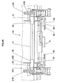
- the figure 1 represents an agricultural tractor TA equipped with a CH loader of known type, comprising a BR stretcher whose lifting and lowering movements are provided by a hydraulic cylinder VL said lifting cylinder.
- a tool holder frame 1 which is articulated at its base, its pivoting being provided by another hydraulic cylinder VB said tipping cylinder or digging cylinder.
- a set of connecting rods BC ensures the connection between the rod of this jack VB and the tool holder frame 1.
- This tool holder frame is provided in the upper part of a pair of hands MA , shaped gutters open upwards, intended to ensure its attachment to a tool 2, for example a bucket.
- This tool 2 has on its dorsal face means of attachment and retention which consist in particular of a pair of bars TA able to engage (by a movement from top to bottom) on hands MA ; in addition, FE fittings located on the back of the tool 2 have OV locking holes through which the locking pins carried by the tool holder frame 1 can pass, so as to ensure the attachment of the tool to this door frame -tool.
- the FE fittings have at their base a bearing zone ZA , in the form of a notch, able to bear against a crossbar BA extending transversely to the base of the frame 1.
- longitudinal direction will be referred to as the horizontal direction corresponding to the direction of travel of the tractor (located in the plane of the drawing sheet of the figure 1 ) and "transverse direction” the direction perpendicular to the longitudinal direction (perpendicular to the plane of the sheet).
- This tool holder frame 1 has a generally symmetrical configuration with respect to the median longitudinal vertical plane.
- the two flanges are fixed by welding at the ends of a pair of high and low crosspieces 6, which consist of cylindrical metal rods.
- X-X ' and Y-Y' respectively denote the axes of the crosspieces 5 and 6.
- the two flanges are connected to each other by a rod 30 located below the upper cross member 5, also horizontal axis and transverse W-W ' .
- the upper crossmember 5 has sleeve-like ends 50 which are fixed to the inner flanges 4.
- Each sleeve 50 is integral with a plate 51 which extends vertically upwards and has inclined chamfered edges 510, respectively 511, which give it the shape of a trapezium.
- lever 7 which is articulated at its base around the rod 30.
- lever 7 comprises an arched body 70 whose base is traversed by a transverse bore 71, which receives the hinge rod 30.
- the lever At its upper end, the lever carries a gutter 700, which is the attachment hand MA which has been mentioned above.
- the trough 700 is approximately the general shape of a "U" whose opening is directed upwards.
- the lever 7 is traversed by a transverse bore 72 in which can engage a rod 52, one end (facing to the right of the figure) carries a handle 53, while its other end is likely to engage, after passing through the bore 72 in a bore 500 provided in the sleeve 50.
- This sleeve therefore has a tubular shape.
- the length of the rod 52 is greater than the mutual spacing of the set of plates 3 and 4.
- Suitable means not shown, are provided to ensure the locking of this rod 52 in this dark position, shown on the figure 2 .
- the two rods 52 serve as hooking bars for a tool according to a second standard.
- the pivoting lever 7 is in an erect position so that its bore 72 is centered on the axis X-X ' , the introduction of the rod 52 in the bore 72 and in the drilling of the sleeve 50 a for effect to maintain the lever 7 and, correspondingly, the hand 700 in its erect position; it is an active position in which the hand 700 is adapted to receive a gripping bar which is provided with a tool complies with the first standard.
- a locking device 8 which, in a known manner, comprises an operating lever 81 adapted to provide displacements in axial translation, along an axis referenced Z-Z ' , of two locking rods. coaxial 80, via a set of rods 811.
- these displacements can be controlled by a hydraulic cylinder.
- the lever 81 is bent at the bottom; it is articulated about an axis 810 on a plate 62 which is carried by a stirrup 60, in the shape of a "U" returned, whose lateral branches are fixed, for example by welding, on the top of the bottom rail 6.
- the branches 61 have orifices which allow the passage and the guide of the locking rods 80; a light 600 provided in the upper horizontal leg of the stirrup 60 allows the passage and the movement of one of the links 811 and the lower part of the lever 81.
- the lateral pivoting of the control lever 81, around its hinge axis 810, ensures the simultaneous movement of the two rods 80 outwards (for locking) or inwards (for unlocking), in the direction of this pivoting.
- each of the inner plates 4 of the flange set 3-4 is mounted a support member 9; it affects the shape of a transverse horizontal axis roller (parallel to Y-Y ') carried by a small lever 90 hinged about an axis 900 at the base of the plate 4.
- the roller 9 extends between this lever 900 of arcuate shape, and a bearing element 91, also of arcuate shape.
- roller 9 By rotating the roller 9 about the axis 900, it can be brought to a low position, in which the elements 90 and 91 are in abutment against the crossbar 6, or in a raised position designated 9 '(retracted position shown in broken lines on the right of the figure 2 ).
- the plates 4 have a large central notch 40, directed forward (towards the tool to receive) which allows the movement of the member 9 in its pivoting movement.
- Suitable indexing and locking means are provided to maintain the support members 9 in their retracted high position.
- the figure 3 represents the dorsal surface of a tool belonging to a first standard, of the type marketed by MAILLEUX.
- the coupling elements of this tool on the tool holder frame essentially comprise a pair of vertical fittings 20a which run from the upper part to the lower part of the dorsal face of the body, to which they are welded, as well as a pair of legs 20'A, each located vis-à-vis the upper part of each fitting, at a distance from it, outwardly.
- each fitting 20A and the associated tab 20'A is fixed a bar 21 A of horizontal and transverse axis.
- the two bars 21A equipping the tool are located symmetrically on either side of a longitudinal central vertical axis and are arranged coaxially, that is to say in the extension of one another.
- the fittings 20A In their lower part, the fittings 20A have a locking orifice 22A and a notch 23A.
- the orifices 22A are also coaxial, as are the notches.
- the tool of figure 4 which conforms to a second standard, in this case the German standard designated "DGS" is also a body 2B, whose back face is provided with a pair of fittings 20B similar to those of the previously described tool 2A.
- DGS German standard
- fittings 20B are slightly closer to each other than the fittings 20A.
- a hook 21B On the outer side, at the upper part of each fitting, is fixed a hook 21B whose active part has the general shape of a beak "U" returned, forming a semi-cylindrical cavity.
- the fittings 20B have in the lower part a locking hole 22 B.
- these fittings have a flat edge 23B which acts as a bearing surface against the tool holder, as will be seen below.
- the 2C tool shown in figure 5 is a claw. It is a third standard compliant service tool on the Swedish market, designated "SMS”.
- the fittings provided on the back of these tools are vertical flat rods 20C which are provided in the upper part of a hook 21C having the shape of a spout whose opening, semi-cylindrical, is turned downwards.
- each fitting At the base of each fitting is provided a semi-cylindrical eyelet 22C. It has a transverse opening acting as a locking orifice.
- the operator on the agricultural tractor can manipulate the tool holder as he wishes, tilting it more or less with the tipping cylinder and lifting it more or less. , thanks to the lifting cylinder, to engage it against the dorsal surface of the tool, and to hook the tool.
- the levers 7 are raised and immobilized in their raised position, thanks to the rods 52, as explained above.
- Both hands 700 are thus in the active position.
- each hand 700 corresponds to the game close engagement
- the length of each bar 21 A corresponds, of course, to the mutual spacing of these bars.
- the width of the gutter that constitutes each hand 700 corresponds, with the interlocking clearance, to the diameter of a bar 2 1 A.
- this diameter is equal to 50 mm.
- the position of the rollers 9 relative to the hands 700 when these rollers are in their active position of the figure 6 is determined such that when the bars 21A are engaged in the hands 700, each roller bears in the notch 23A of a fitting.
- the position of the locking rods 80 is determined such that after latching and pressing the tool 2A on the tool holder 1, the locking holes 22A are each in the axial alignment Z-Z ' said rods 80.
- the rods 52 have a diameter which corresponds to the interlocking clearance, to the width of the openings of the hooks 21 B.
- this diameter is 40 mm.
- the orifices 22B are positioned opposite the locking rods 80 and the support edges 23B of the tool bear against the rollers 9.
- the levers 7 are retracted (in a position referenced 7 '); the rollers 9 are also retracted, by lifting, in a referenced position 9 '.
- this diameter is 60 mm.
- the locking holes 22B and 22C have a smaller diameter than the locking holes 22A of the tool 2A.
- these diameters are 20 mm for tools 2B and 2C and 30 mm for tool 2A.
- the locking rods 80 have a diameter adapted to engage directly in an orifice 22B or 22C. Their diameter is therefore slightly less than 20 mm.
- the rod 80 is integral at its end with a bar 83.
- the latter is traversed by a bore which is engaged on the end portion of the rod 80, a pin 830 ensuring the complete joining of the bar 83 with the rod 80 .
- the bar 83 extends perpendicular to the rod 80, substantially in a horizontal plane.
- the locking device also comprises an articulated lever 87, which can pivot in its central part around a vertical axis 88.
- This axis is carried by a plate referenced 63 on the figure 2 .
- this lever 87 is integral with a sleeve 800.
- a connecting rod 84 connects one end of the bar 83 with the other end of the lever 87.
- the rod 84 is directly articulated, via an axis 86, on the lever 87.
- This rod has a light 840 inside which engages a finger 85 integral with the bar 83.
- the sleeve 800 has a diameter d 2 greater than the diameter d 1 of the rod 80.
- the sleeve 800 is tubular; it has a cylindrical central opening 801 able to engage, with a certain clearance, on the end portion of the rod 80.
- Reference t indicates the trajectory of the center of the sleeve 800 during this pivoting; it is a trajectory in an arc of a circle, tangent to the axis of the rod 80.
- the opening 801 inside the sleeve 800 is bordered by a conical inlet surface 801 'constituting a flared mouthpiece which allows this engagement at the end of the pivoting stroke of the lever 87.
- the diameters d 1 and d 2 correspond, with the engagement clearance, to the diameters D 1 and D 2 corresponding, respectively, to the diameters of the locking holes of the tools according to the second and third standards, on the one hand (20 mm ), and the first standard, on the other hand (30 mm).
- the mutual spacing of the orifices 22C is slightly smaller than the mutual spacing of the orifices 22B, which itself is slightly smaller than the mutual spacing of the orifices 22A.
- the locking device is thus positioned and dimensioned so that the fittings 20B and 20C are positioned facing the end portion of the rods 80, between the bar 83 and the sleeve 800 (FIGS. figure 17 ).
- fitting 20A is positioned at the sleeve 800 ( figure 18 ).
- each fitting 20 being placed between the end of a rod 80 and the associated sleeve 800, after which the locking is carried out ( figure 17 or 18 ).
- the view of the figure 19 which refers to a tool according to the first standard, shows that, firstly, the bars 21A are engaged in the hands 700, and that the fittings 20A are at the sleeves 800, which ensure the locking.
- fittings 21B are opposite the rods 52, outside the sleeves 50 and the plates 51; it is also observed that the fittings 20B are opposite the portions 80 of the locking rods (which pass through them).
- the hooks 21C are in engagement with the portions of the sleeves 50 situated inward with respect to the plates 51; it is the internal inclined edges 511 of the plates 51 which ensure the guiding and centering of the tool relative to the tool holder frame during the approach phase, the hooks this time being placed inside the two pads 51.
- the locking holes 22C are positioned relative to the rods 80, which pass through them, in a position slightly inwardly offset with respect to the position occupied by the orifices 22B.
- a tool holder frame according to the invention although originally designed to equip an agricultural tractor can also find applications in other areas, in particular for equipping public works machinery, for earthworks for example.
Landscapes
- Engineering & Computer Science (AREA)
- Mechanical Engineering (AREA)
- Mining & Mineral Resources (AREA)
- Civil Engineering (AREA)
- General Engineering & Computer Science (AREA)
- Structural Engineering (AREA)
- Component Parts Of Construction Machinery (AREA)
- Agricultural Machines (AREA)
- Catching Or Destruction (AREA)
- Handcart (AREA)
- Earth Drilling (AREA)
- Feeding And Watering For Cattle Raising And Animal Husbandry (AREA)
- Manipulator (AREA)
Claims (11)
- Geräteträgerrahmen für einen Ladearm, insbesondere für den landwirtschaftlichen Einsatz, der ein Paar identischer Aufnahmen zum Einhängen (700) umfasst, wobei diese die Form eines Rinnenabschnitts mit in etwa U-förmigem Querschnitt, dessen Öffnung nach oben gerichtet ist, haben und wobei diese beiden Aufnahmen (700) symmetrisch auf beiden Seiten der vertikalen und in Längsrichtung verlaufenden Mittelebene des Geräteträgerrahmens (1) angeordnet sind, und dies koaxial entlang einer quer verlaufenden horizontalen Achse, wobei dieser Geräteträgerrahmen dafür vorgesehen ist, ein Werkzeug (2A) anzukuppeln, das einen gegebenen Montagestandard erfüllt, der als "erster Standard" bezeichnet wird, und dessen Rückseite im oberen Teil mit einem Paar koaxialer Stäbe (21A) ausgestattet ist, die so bemessen und positioniert sind, dass jeder von ihnen sich in eine Aufnahmen zum Einhängen (700) einfügen und in ihr aufgenommen werden kann, derart, dass das dem ersten Standard entsprechende Werkzeug (2A) damit korrekt vom Geräteträgerrahmen (1) gehalten wird, dadurch gekennzeichnet, dass er außerdem wenigstens ein Paar koaxialer Einhängstäbe (52) umfasst, die symmetrisch auf beiden Seiten der vertikalen und in Längsrichtung verlaufenden Mittelebene des Geräteträgerrahmens angeordnet sind und die das Ankuppeln dieses letzteren an ein Werkzeug (2B) gestatten, das wenigstens einen weiteren Montagestandard erfüllt, der als "zweiter Standard" bezeichnet wird, und dessen Rückseite im oberen Teil mit einem Paar koaxialer Haken (21B) ausgestattet ist, deren Öffnung nach unten gerichtet ist und die so bemessen und positioniert sind, dass jeder von ihnen auf einem Einhängstab (52) eingreifen und ihn derart festhalten kann, dass das dem zweiten Standard entsprechende Werkzeug (2B) damit korrekt vom Geräteträgerrahmen (1) gehalten wird.
- Geräteträgerrahmen nach Anspruch 1, dadurch gekennzeichnet, dass jede der Aufnahmen zum Einhängen (700) durch einen schwenkbar aufgehängten Hebel (7) getragen wird, der durch Schwenken wahlweise folgendes einnehmen kann: entweder eine aufgerichtete aktive Position, in der sie dazu fähig ist, einen Stab (21A) aufzunehmen und zu tragen, der fest mit einem dem ersten Standard entsprechenden Werkzeug verbunden ist, oder eine tiefe inaktive Position, in der sie derart eingezogen ist, dass sie das Kuppeln des Geräteträgerrahmens mit einem dem zweiten Standard entsprechenden Werkzeug (2B) nicht behindert, und insbesondere nicht das Eingreifen der Haken (21B), mit denen dieses Werkzeug ausgestattet ist, auf den Stäben zum Einhängen (21 A).
- Geräteträgerrahmen nach Anspruch 2, dadurch gekennzeichnet, dass er ein Gestell umfasst, das eine obere (5) und untere (6) horizontale Querstange umfasst, die an jedem ihrer Enden durch ein Paar paralleler Platten (3-4) verbunden sind, die sich im wesentlichen in vertikalen und in Längsrichtung verlaufenden Ebenen erstrecken und die einen Satz von Seitenplatten bilden, zwischen denen der schwenkbare Hebel (7) montiert ist.
- Geräteträgerrahmen nach Anspruch 3, dadurch gekennzeichnet, dass jeder der Hebel (7) eine Öffnung in Querrichtung (72) umfasst, die dafür geeignet ist, von einer abnehmbaren zylindrischen Stange (52) durchzogen zu werden, die von einem der Seitenplattensätze (3-4) getragen wird, wobei diese Stange dafür eingerichtet ist, wahlweise eine der beiden folgenden Aufgaben zu erfüllen:- Halten des Hebels (7) in der aufgerichteten aktiven Position, wenn sie in die Öffnung (72) eingeführt ist,- Dienen als Stab zum Einhängen (52), der dazu geeignet ist, mit dem Haken (21B) eines dem zweiten Standard entsprechenden Werkzeugs (2B) zusammenzuarbeiten, wenn sie nicht in die Öffnung eingeführt ist und der Hebel (7) in seine tiefe inaktive Position eingezogen ist.
- Geräteträgerrahmen nach Anspruch 4, dadurch gekennzeichnet, dass die Endabschnitte der oberen Querstange (5) an den inneren Seitenplatten (4) der Seitenplattensätze befestigt sind und dass sie röhrenförmig sind, wobei ihr Innendurchmesser so dimensioniert ist, dass er das Einführen und Zentrieren eines Endabschnitts der abnehmbaren zylindrischen Stange (52) gestattet, wenn diese in den Seitenplattensatz (3-4) eingeführt ist.
- Geräteträgerrahmen nach einem der Ansprüche 1 bis 5, dadurch gekennzeichnet, dass er zwei unterschiedliche Paare von Stäben zum Einhängen (52; 50) umfasst, die einen unterschiedlichen Durchmesser haben und deren gegenseitiger Abstand in Querrichtung unterschiedlich ist, wobei eines der Stabpaare (52) dazu eingerichtet ist, mit einem Paar Haken (21B) zusammenzuarbeiten, die fest mit einem dem zweiten Standard entsprechenden Werkzeug (2B) verbunden sind, und das andere mit einem Paar Haken (21 C), die fest mit einem Werkzeug (2C) verbunden sind, das einem dritten Standard entspricht.
- Geräteträgerrahmen nach den Ansprüchen 5 und 6 in Kombination, dadurch gekennzeichnet, dass die Endabschnitte der oberen Querstange (5) zylindrische Muffen (50) sind, die an die inneren Seitenplatten angefügt sind, die einen Außendurchmesser haben, der größer als derjenige der abnehmbaren Stangen (52) ist, und die dafür eingerichtet sind, als Stäbe zum Einhängen zu dienen, die dazu geeignet sind, mit den Haken (21C) eines dem dritten Standard entsprechenden Werkzeugs (2C) zusammenzuarbeiten.
- Geräteträgerrahmen nach Anspruch 7, dadurch gekennzeichnet, dass jede der zylindrischen Muffen (50) fest mit einer Platte (51) verbunden ist, die abgeschrägte Ränder (510, 511) hat, wobei diese Platte dafür eingerichtet ist, die relative Führung des Geräteträgerrahmens (1) und des dem zweiten oder dritten Standard entsprechenden Werkzeugs (2B, 2C) während der Phase der Annäherung mit dem Ziel ihres Ankuppelns zu erleichtern und dafür, ihre gute gegenseitige Zentrierung nach dem Ankuppeln sicherzustellen.
- Geräteträgerrahmen nach Anspruch 3, dadurch gekennzeichnet, dass er im unteren Teil ein Paar einziehbarer Abstützelemente (9) umfasst, die sich in der Nähe der Enden der unteren Querstange (6) befinden, wobei jedes von ihnen dazu geeignet ist, wahlweise folgendes einzunehmen: entweder eine hervorstehende und aktive Position, in der es sich gegen Beschlagteile (20A; 20B) abstützt, die fest mit der Rückseite des Werkzeugs (2A; 2B) verbunden sind, wenn letzteres an den Geräteträgerrahmen (1) angekuppelt ist, oder eine eingezogene und inaktive Position, in der es die untere Querstange (6) ist, die diese Abstützung bereitstellt, und zwar direkt gegen den unteren Bereich der Rückseite des Werkzeugs (2C).
- Geräteträgerrahmen nach Anspruch 9, dadurch gekennzeichnet, dass die Abstützelemente (9) horizontale Rollen mit quer verlaufender Achse sind, die von einem Hebel (90) getragen werden, der um eine Achse (900) schwenkbar ist, die von einer der inneren Seitenplatten (4) getragen wird, wobei deren Einziehen durch das Anheben dieser Hebel (90) ausgeführt wird, wohingegen ihre Verschiebung in die aktive Position durch das Schwenken dieser Hebel (90) nach unten geschieht, wobei die tiefe Querstange (6) dann als Anschlag für die Abstützelemente (9) dient.
- Geräteträgerrahmen nach wenigstens einem der vorhergehenden Ansprüche, dadurch gekennzeichnet, dass er Elemente (80; 800) zur Verriegelung des Werkzeugs am Geräteträgerrahmen umfasst, die dafür eingerichtet sind, sowohl in Verriegelungsöffnungen (22A) einzudringen, die in Beschlagteilen (20A) vorgesehen sind, die fest mit einem dem ersten Standard entsprechenden Werkzeug (2A) verbunden sind, wie auch in Verriegelungsöffnungen (22B; 22C) mit einem verschiedenen Durchmesser, die in Beschlagteilen (20B; 20C) vorgesehen sind, die fest mit einem dem zweiten und/oder dritten Standard entsprechenden Werkzeug (2B, 2C) verbunden sind.
Applications Claiming Priority (2)
| Application Number | Priority Date | Filing Date | Title |
|---|---|---|---|
| FR0403913 | 2004-04-14 | ||
| FR0403913A FR2869055B1 (fr) | 2004-04-14 | 2004-04-14 | Cadre porte-outil a caractere polyvalent pour chargeur, notamment a usage agricole. |
Publications (3)
| Publication Number | Publication Date |
|---|---|
| EP1586709A2 EP1586709A2 (de) | 2005-10-19 |
| EP1586709A3 EP1586709A3 (de) | 2006-07-05 |
| EP1586709B1 true EP1586709B1 (de) | 2008-11-12 |
Family
ID=34942742
Family Applications (1)
| Application Number | Title | Priority Date | Filing Date |
|---|---|---|---|
| EP05364012A Expired - Lifetime EP1586709B1 (de) | 2004-04-14 | 2005-03-01 | Mehrzweck-Werkzeug-Trägerrahmen für einen Lader, insbesondere für einen landwirtschaftlichen Lader |
Country Status (4)
| Country | Link |
|---|---|
| EP (1) | EP1586709B1 (de) |
| AT (1) | ATE414199T1 (de) |
| DE (1) | DE602005010929D1 (de) |
| FR (1) | FR2869055B1 (de) |
Cited By (3)
| Publication number | Priority date | Publication date | Assignee | Title |
|---|---|---|---|---|
| DE102009046213A1 (de) | 2009-10-30 | 2011-05-19 | Wilhelm Stoll Maschinenfabrik Gmbh | Wechselrahmen für einen Frontlader |
| EP2573278A1 (de) | 2011-09-23 | 2013-03-27 | Deere & Company | Werkzeugträger |
| USD1026968S1 (en) | 2022-11-04 | 2024-05-14 | Deere & Company | Loader carrier for implements |
Families Citing this family (4)
| Publication number | Priority date | Publication date | Assignee | Title |
|---|---|---|---|---|
| DE102012109295A1 (de) * | 2012-09-29 | 2014-04-03 | Gerhard Schwendner | Werkzeugwechselrahmen |
| DE102014218197A1 (de) | 2014-09-11 | 2016-03-17 | Deere & Company | Frontladeranordnung |
| US10316488B2 (en) * | 2016-09-16 | 2019-06-11 | Cnh Industrial America Llc | Universal backhoe coupler |
| CH713758A1 (de) * | 2017-05-05 | 2018-11-15 | Martin Umwelt & Energietech | Schnellwechselkupplung zum Befestigen eines Anbaugeräts an einer Baumaschine, vorzugsweise an einem Baggerarm. |
Family Cites Families (6)
| Publication number | Priority date | Publication date | Assignee | Title |
|---|---|---|---|---|
| DE1257057B (de) * | 1965-08-26 | 1967-12-21 | Alfred Hagelstein Maschinenfab | Vorrichtung zur auswechselbaren Halterung von Arbeitsgeraeten wie Ladeschaufeln am kippbar am den Hubarmen einer Lademaschine gelagerten Geraettraeger |
| SE447282B (sv) * | 1985-11-19 | 1986-11-03 | Alo Maskiner Ab | Anordning for att festa redskap vid traktor |
| US4984957A (en) * | 1988-08-08 | 1991-01-15 | Kubota, Ltd. | Work-implement adapter for front loader |
| JPH04237402A (ja) * | 1991-01-16 | 1992-08-25 | Kubota Corp | 車輌の作業機装着装置 |
| US6227792B1 (en) * | 1997-06-30 | 2001-05-08 | Caterpillar S.A.R.L. | Vertical engagement hydraulic tool coupler |
| FR2776316B1 (fr) * | 1998-03-18 | 2000-06-16 | Mailleux Sa | Systeme de verrouillage hydraulique d'un outil de chargeur |
-
2004
- 2004-04-14 FR FR0403913A patent/FR2869055B1/fr not_active Expired - Fee Related
-
2005
- 2005-03-01 AT AT05364012T patent/ATE414199T1/de not_active IP Right Cessation
- 2005-03-01 DE DE602005010929T patent/DE602005010929D1/de not_active Expired - Lifetime
- 2005-03-01 EP EP05364012A patent/EP1586709B1/de not_active Expired - Lifetime
Cited By (5)
| Publication number | Priority date | Publication date | Assignee | Title |
|---|---|---|---|---|
| DE102009046213A1 (de) | 2009-10-30 | 2011-05-19 | Wilhelm Stoll Maschinenfabrik Gmbh | Wechselrahmen für einen Frontlader |
| DE102009046213B4 (de) * | 2009-10-30 | 2014-02-13 | Wilhelm Stoll Maschinenfabrik Gmbh | Wechselrahmen für einen Frontlader |
| EP2573278A1 (de) | 2011-09-23 | 2013-03-27 | Deere & Company | Werkzeugträger |
| DE102011083350A1 (de) | 2011-09-23 | 2013-03-28 | Deere & Company | Werkzeugträger |
| USD1026968S1 (en) | 2022-11-04 | 2024-05-14 | Deere & Company | Loader carrier for implements |
Also Published As
| Publication number | Publication date |
|---|---|
| DE602005010929D1 (de) | 2008-12-24 |
| EP1586709A2 (de) | 2005-10-19 |
| EP1586709A3 (de) | 2006-07-05 |
| FR2869055A1 (fr) | 2005-10-21 |
| FR2869055B1 (fr) | 2006-07-07 |
| ATE414199T1 (de) | 2008-11-15 |
Similar Documents
| Publication | Publication Date | Title |
|---|---|---|
| WO2002020906A1 (fr) | Procede et systeme d'accouplement mecanique et multifluidique d'un outil sur un cadre porte-outil | |
| EP1774106B1 (de) | Vorrichtung zur kopplung eines laders an einen traktor | |
| EP1586709B1 (de) | Mehrzweck-Werkzeug-Trägerrahmen für einen Lader, insbesondere für einen landwirtschaftlichen Lader | |
| EP3284330A1 (de) | Landwirtschaftliche maschine mit einer vorrichtung zur unterstützung des zusammenklappens | |
| EP1586708B1 (de) | Vorrichtung für die Verriegelung eines Werkzeugs an den Rahmen eines Laders, insbesondere eines landwirtschaftlichen Laders | |
| EP0244323B1 (de) | Hebevorrichtung, insbesondere zur Handhabung und zum Öffnen von Behältern, bestehend aus zwei Klappkokillen | |
| CA3038162A1 (fr) | Unite d'enfouissement de produit agricole et machine agricole comportant une telle unite | |
| FR2470204A1 (fr) | Dispositif de deplacement lateral pour instruments de terrassement | |
| BE442612A (de) | ||
| EP0219385A2 (de) | Papierkorb | |
| EP2659772B1 (de) | Hüttenvorrichtung für Tiere | |
| FR2563685A1 (fr) | Faucheuse | |
| EP0527086A1 (de) | Vorrichtung zur Kupplung und Verbindung eines Endes einer Traverse mit einem Pfosten, und Gerüst mit dieser Traverse, die an beiden Enden mit dieser Vorrichtung versehen ist | |
| WO2012085418A1 (fr) | Cadre porte-outil pour chargeur, notamment pour chargeur equipant un engin agricole, permettant de securiser le verrouillage d'un outil | |
| FR2610613A1 (fr) | Appareil pour le levage, le deplacement et la pose de tampons de regard et de grilles d'ecoulement | |
| EP0390691B1 (de) | Stützrad für einen Drehpflug, für Arbeit und Transport | |
| FR2640111A1 (fr) | Herse rotative | |
| FR2671450A1 (fr) | Dispositif d'attelage d'un semoir a une machine de travail du sol. | |
| FR2818492A1 (fr) | Outil de jardinage, de type beche ou fourche-beche | |
| FR2525853A1 (fr) | Potence d'attelage pour le dispositif de levage a trois points d'un tracteur | |
| FR2575027A1 (fr) | Dispositif d'attelage pour chargeur frontal de tracteur | |
| EP1256268B1 (de) | Kupplungsvorrichtung zwischen Sähmaschine und Bodenbearbeitungsgerät mit Befestigungsstäben | |
| EP4636168A1 (de) | Schnellkupplung für baumaschinen | |
| EP4703318A1 (de) | Hebetisch zur reparatur und/oder wartung und/oder überwachung eines rollenden fahrzeugs | |
| EP4636167A1 (de) | Schnellkupplung für baumaschinen |
Legal Events
| Date | Code | Title | Description |
|---|---|---|---|
| PUAI | Public reference made under article 153(3) epc to a published international application that has entered the european phase |
Free format text: ORIGINAL CODE: 0009012 |
|
| AK | Designated contracting states |
Kind code of ref document: A2 Designated state(s): AT BE BG CH CY CZ DE DK EE ES FI FR GB GR HU IE IS IT LI LT LU MC NL PL PT RO SE SI SK TR |
|
| AX | Request for extension of the european patent |
Extension state: AL BA HR LV MK YU |
|
| PUAL | Search report despatched |
Free format text: ORIGINAL CODE: 0009013 |
|
| AK | Designated contracting states |
Kind code of ref document: A3 Designated state(s): AT BE BG CH CY CZ DE DK EE ES FI FR GB GR HU IE IS IT LI LT LU MC NL PL PT RO SE SI SK TR |
|
| AX | Request for extension of the european patent |
Extension state: AL BA HR LV MK YU |
|
| 17P | Request for examination filed |
Effective date: 20061213 |
|
| AKX | Designation fees paid |
Designated state(s): AT BE BG CH CY CZ DE DK EE ES FI FR GB GR HU IE IS IT LI LT LU MC NL PL PT RO SE SI SK TR |
|
| RAP1 | Party data changed (applicant data changed or rights of an application transferred) |
Owner name: MAILLEUX |
|
| GRAP | Despatch of communication of intention to grant a patent |
Free format text: ORIGINAL CODE: EPIDOSNIGR1 |
|
| GRAS | Grant fee paid |
Free format text: ORIGINAL CODE: EPIDOSNIGR3 |
|
| GRAA | (expected) grant |
Free format text: ORIGINAL CODE: 0009210 |
|
| AK | Designated contracting states |
Kind code of ref document: B1 Designated state(s): AT BE BG CH CY CZ DE DK EE ES FI FR GB GR HU IE IS IT LI LT LU MC NL PL PT RO SE SI SK TR |
|
| REG | Reference to a national code |
Ref country code: GB Ref legal event code: FG4D Free format text: NOT ENGLISH |
|
| REG | Reference to a national code |
Ref country code: CH Ref legal event code: EP |
|
| REG | Reference to a national code |
Ref country code: IE Ref legal event code: FG4D Free format text: LANGUAGE OF EP DOCUMENT: FRENCH |
|
| REF | Corresponds to: |
Ref document number: 602005010929 Country of ref document: DE Date of ref document: 20081224 Kind code of ref document: P |
|
| LTIE | Lt: invalidation of european patent or patent extension |
Effective date: 20081112 |
|
| PG25 | Lapsed in a contracting state [announced via postgrant information from national office to epo] |
Ref country code: ES Free format text: LAPSE BECAUSE OF FAILURE TO SUBMIT A TRANSLATION OF THE DESCRIPTION OR TO PAY THE FEE WITHIN THE PRESCRIBED TIME-LIMIT Effective date: 20090223 Ref country code: AT Free format text: LAPSE BECAUSE OF FAILURE TO SUBMIT A TRANSLATION OF THE DESCRIPTION OR TO PAY THE FEE WITHIN THE PRESCRIBED TIME-LIMIT Effective date: 20081112 Ref country code: LT Free format text: LAPSE BECAUSE OF FAILURE TO SUBMIT A TRANSLATION OF THE DESCRIPTION OR TO PAY THE FEE WITHIN THE PRESCRIBED TIME-LIMIT Effective date: 20081112 |
|
| NLV1 | Nl: lapsed or annulled due to failure to fulfill the requirements of art. 29p and 29m of the patents act | ||
| PG25 | Lapsed in a contracting state [announced via postgrant information from national office to epo] |
Ref country code: SI Free format text: LAPSE BECAUSE OF FAILURE TO SUBMIT A TRANSLATION OF THE DESCRIPTION OR TO PAY THE FEE WITHIN THE PRESCRIBED TIME-LIMIT Effective date: 20081112 Ref country code: FI Free format text: LAPSE BECAUSE OF FAILURE TO SUBMIT A TRANSLATION OF THE DESCRIPTION OR TO PAY THE FEE WITHIN THE PRESCRIBED TIME-LIMIT Effective date: 20081112 Ref country code: PL Free format text: LAPSE BECAUSE OF FAILURE TO SUBMIT A TRANSLATION OF THE DESCRIPTION OR TO PAY THE FEE WITHIN THE PRESCRIBED TIME-LIMIT Effective date: 20081112 Ref country code: NL Free format text: LAPSE BECAUSE OF FAILURE TO SUBMIT A TRANSLATION OF THE DESCRIPTION OR TO PAY THE FEE WITHIN THE PRESCRIBED TIME-LIMIT Effective date: 20081112 Ref country code: IS Free format text: LAPSE BECAUSE OF FAILURE TO SUBMIT A TRANSLATION OF THE DESCRIPTION OR TO PAY THE FEE WITHIN THE PRESCRIBED TIME-LIMIT Effective date: 20090312 |
|
| REG | Reference to a national code |
Ref country code: IE Ref legal event code: FD4D |
|
| PG25 | Lapsed in a contracting state [announced via postgrant information from national office to epo] |
Ref country code: RO Free format text: LAPSE BECAUSE OF FAILURE TO SUBMIT A TRANSLATION OF THE DESCRIPTION OR TO PAY THE FEE WITHIN THE PRESCRIBED TIME-LIMIT Effective date: 20081112 Ref country code: IE Free format text: LAPSE BECAUSE OF FAILURE TO SUBMIT A TRANSLATION OF THE DESCRIPTION OR TO PAY THE FEE WITHIN THE PRESCRIBED TIME-LIMIT Effective date: 20081112 Ref country code: EE Free format text: LAPSE BECAUSE OF FAILURE TO SUBMIT A TRANSLATION OF THE DESCRIPTION OR TO PAY THE FEE WITHIN THE PRESCRIBED TIME-LIMIT Effective date: 20081112 Ref country code: DK Free format text: LAPSE BECAUSE OF FAILURE TO SUBMIT A TRANSLATION OF THE DESCRIPTION OR TO PAY THE FEE WITHIN THE PRESCRIBED TIME-LIMIT Effective date: 20081112 Ref country code: BG Free format text: LAPSE BECAUSE OF FAILURE TO SUBMIT A TRANSLATION OF THE DESCRIPTION OR TO PAY THE FEE WITHIN THE PRESCRIBED TIME-LIMIT Effective date: 20090212 |
|
| PG25 | Lapsed in a contracting state [announced via postgrant information from national office to epo] |
Ref country code: SE Free format text: LAPSE BECAUSE OF FAILURE TO SUBMIT A TRANSLATION OF THE DESCRIPTION OR TO PAY THE FEE WITHIN THE PRESCRIBED TIME-LIMIT Effective date: 20090212 Ref country code: PT Free format text: LAPSE BECAUSE OF FAILURE TO SUBMIT A TRANSLATION OF THE DESCRIPTION OR TO PAY THE FEE WITHIN THE PRESCRIBED TIME-LIMIT Effective date: 20090413 Ref country code: CZ Free format text: LAPSE BECAUSE OF FAILURE TO SUBMIT A TRANSLATION OF THE DESCRIPTION OR TO PAY THE FEE WITHIN THE PRESCRIBED TIME-LIMIT Effective date: 20081112 |
|
| PLBE | No opposition filed within time limit |
Free format text: ORIGINAL CODE: 0009261 |
|
| STAA | Information on the status of an ep patent application or granted ep patent |
Free format text: STATUS: NO OPPOSITION FILED WITHIN TIME LIMIT |
|
| BERE | Be: lapsed |
Owner name: MAILLEUX Effective date: 20090331 |
|
| PG25 | Lapsed in a contracting state [announced via postgrant information from national office to epo] |
Ref country code: SK Free format text: LAPSE BECAUSE OF FAILURE TO SUBMIT A TRANSLATION OF THE DESCRIPTION OR TO PAY THE FEE WITHIN THE PRESCRIBED TIME-LIMIT Effective date: 20081112 |
|
| 26N | No opposition filed |
Effective date: 20090813 |
|
| PG25 | Lapsed in a contracting state [announced via postgrant information from national office to epo] |
Ref country code: MC Free format text: LAPSE BECAUSE OF NON-PAYMENT OF DUE FEES Effective date: 20090331 |
|
| REG | Reference to a national code |
Ref country code: CH Ref legal event code: PL |
|
| PG25 | Lapsed in a contracting state [announced via postgrant information from national office to epo] |
Ref country code: CH Free format text: LAPSE BECAUSE OF NON-PAYMENT OF DUE FEES Effective date: 20090331 Ref country code: LI Free format text: LAPSE BECAUSE OF NON-PAYMENT OF DUE FEES Effective date: 20090331 |
|
| PG25 | Lapsed in a contracting state [announced via postgrant information from national office to epo] |
Ref country code: BE Free format text: LAPSE BECAUSE OF NON-PAYMENT OF DUE FEES Effective date: 20090331 |
|
| PG25 | Lapsed in a contracting state [announced via postgrant information from national office to epo] |
Ref country code: GR Free format text: LAPSE BECAUSE OF FAILURE TO SUBMIT A TRANSLATION OF THE DESCRIPTION OR TO PAY THE FEE WITHIN THE PRESCRIBED TIME-LIMIT Effective date: 20090213 |
|
| PG25 | Lapsed in a contracting state [announced via postgrant information from national office to epo] |
Ref country code: IT Free format text: LAPSE BECAUSE OF FAILURE TO SUBMIT A TRANSLATION OF THE DESCRIPTION OR TO PAY THE FEE WITHIN THE PRESCRIBED TIME-LIMIT Effective date: 20081112 |
|
| PG25 | Lapsed in a contracting state [announced via postgrant information from national office to epo] |
Ref country code: LU Free format text: LAPSE BECAUSE OF NON-PAYMENT OF DUE FEES Effective date: 20090301 |
|
| PG25 | Lapsed in a contracting state [announced via postgrant information from national office to epo] |
Ref country code: HU Free format text: LAPSE BECAUSE OF FAILURE TO SUBMIT A TRANSLATION OF THE DESCRIPTION OR TO PAY THE FEE WITHIN THE PRESCRIBED TIME-LIMIT Effective date: 20090513 |
|
| PGFP | Annual fee paid to national office [announced via postgrant information from national office to epo] |
Ref country code: DE Payment date: 20110429 Year of fee payment: 7 Ref country code: FR Payment date: 20110412 Year of fee payment: 7 |
|
| PG25 | Lapsed in a contracting state [announced via postgrant information from national office to epo] |
Ref country code: TR Free format text: LAPSE BECAUSE OF FAILURE TO SUBMIT A TRANSLATION OF THE DESCRIPTION OR TO PAY THE FEE WITHIN THE PRESCRIBED TIME-LIMIT Effective date: 20081112 |
|
| PGFP | Annual fee paid to national office [announced via postgrant information from national office to epo] |
Ref country code: GB Payment date: 20110426 Year of fee payment: 7 |
|
| PG25 | Lapsed in a contracting state [announced via postgrant information from national office to epo] |
Ref country code: CY Free format text: LAPSE BECAUSE OF FAILURE TO SUBMIT A TRANSLATION OF THE DESCRIPTION OR TO PAY THE FEE WITHIN THE PRESCRIBED TIME-LIMIT Effective date: 20081112 |
|
| GBPC | Gb: european patent ceased through non-payment of renewal fee |
Effective date: 20120301 |
|
| REG | Reference to a national code |
Ref country code: FR Ref legal event code: ST Effective date: 20121130 |
|
| PG25 | Lapsed in a contracting state [announced via postgrant information from national office to epo] |
Ref country code: GB Free format text: LAPSE BECAUSE OF NON-PAYMENT OF DUE FEES Effective date: 20120301 Ref country code: FR Free format text: LAPSE BECAUSE OF NON-PAYMENT OF DUE FEES Effective date: 20120402 |
|
| REG | Reference to a national code |
Ref country code: DE Ref legal event code: R119 Ref document number: 602005010929 Country of ref document: DE Effective date: 20121002 |
|
| PG25 | Lapsed in a contracting state [announced via postgrant information from national office to epo] |
Ref country code: DE Free format text: LAPSE BECAUSE OF NON-PAYMENT OF DUE FEES Effective date: 20121002 |