EP1586683B1 - Greiferband für eine Greiferwebmaschine und Greiferwebmaschine - Google Patents
Greiferband für eine Greiferwebmaschine und Greiferwebmaschine Download PDFInfo
- Publication number
- EP1586683B1 EP1586683B1 EP05006700A EP05006700A EP1586683B1 EP 1586683 B1 EP1586683 B1 EP 1586683B1 EP 05006700 A EP05006700 A EP 05006700A EP 05006700 A EP05006700 A EP 05006700A EP 1586683 B1 EP1586683 B1 EP 1586683B1
- Authority
- EP
- European Patent Office
- Prior art keywords
- layer
- gripper
- rapier band
- rapier
- longitudinal
- Prior art date
- Legal status (The legal status is an assumption and is not a legal conclusion. Google has not performed a legal analysis and makes no representation as to the accuracy of the status listed.)
- Expired - Lifetime
Links
Images


Classifications
-
- D—TEXTILES; PAPER
- D03—WEAVING
- D03D—WOVEN FABRICS; METHODS OF WEAVING; LOOMS
- D03D47/00—Looms in which bulk supply of weft does not pass through shed, e.g. shuttleless looms, gripper shuttle looms, dummy shuttle looms
- D03D47/27—Drive or guide mechanisms for weft inserting
- D03D47/271—Rapiers
- D03D47/272—Rapier bands
Definitions
- This invention relates to a rapier band for a rapier loom.
- the invention also relates to a rapier loom with such a rapier band.
- rapier weaving a weft thread is grabbed by means of at least one gripper and pulled into a shed.
- a gripper is attached to a flexible gripper belt, which is driven by a drive wheel and which is guided by means of guide elements both outside of the shed and within the shed.
- a gripper band made of reinforced plastic used.
- high strength reinforcing fibers are integrated into the rapier band, which are, for example, carbon fibers or Kevlar fibers.
- the gripper belt may additionally have a wear-resistant layer on the longitudinal surfaces which does not contain abrasive fibers.
- Such a rapier band has the disadvantage that the gripper band becomes thicker by such coatings and is therefore less suitable for bending a drive wheel.
- Such coatings are also usually not beneficial when engaging the teeth of a toothed wheel in the openings of the rapier band and usually contribute little to transmit the forces on the teeth of the drive wheel on the gripper belt.
- a rapier band for a rapier loom which consists of one of a plurality of strand and / or bundle-like Fiber group reinforced plastic is made.
- the gripper belt is provided on one of the long sides with a protective layer of an abrasion-resistant material.
- the invention is intended to improve a rapier band of the above type.
- the gripper belt has a substantially rectangular cross section with two narrow longitudinal sides and two wide longitudinal sides, wherein at least one of the wide longitudinal sides of the rapier band is provided only over a part in the direction of its width with at least one layer , which is arranged at a distance from the longitudinal center plane which is flush with a side edge of the base body and flush with the outer surface of the associated longitudinal side of the base body.
- Such a rapier band in which the base body and the at least one layer have a different composition, enables the base body to be composed of materials that give it high strength, and that the at least one layer of materials is composed of a high Wear resistance when rubbed on the warp threads and / or give good sliding properties against warp thread.
- the rapier band includes a row of holes extending in the longitudinal direction of the rapier band and arranged on one of the broad sides of the rapier band, a base body which is located at least in the region of the row of holes, and at least one layer extending in the width of the rapier band at a distance from the row of holes.
- Such a rapier band has the advantage that the rapier band in the region of the base body with the row of holes can be designed as a largely homogeneous part. Since the at least one layer is not in the range of the row of holes in the rapier, this layer can not be replaced by the engagement of the teeth of the drive wheel in the holes of the rapier band. This also has the advantage that the teeth of the drive wheel, which can engage in the holes of the rapier band, over a large contact area away, whereby the wear of the teeth and the holes remains low and a long life is achieved. For this reason, the rapier band is suitable for use in fast weaving machines.
- Such a large contact surface in an above-mentioned homogeneous base body can be achieved in a rapier band according to the invention by a relatively small height of the rapier band, such a rapier band can be easily bent around a drive wheel.
- the at least one layer is in operation on the side facing the warp threads.
- the at least one layer contains no carbon fibers.
- a conventional gripper belt containing carbon fibers there is a risk that the carbon fibers act on the warp threads and damage or blacken the warp threads in this way.
- This blackening is caused by the fact that carbon fibers are released from the rapier band and on the warp threads and in particular on the sizing agent or so-called "sizing agent", with which the warp threads are equipped act.
- a rapier band according to the invention this problem can be avoided.
- the at least one layer of a material for example of the so-called Teflon or PTFE, polytetrafluoroethylene, consist of possibly containing fillers, which has a high wear resistance when rubbed against the warp threads and / or good sliding properties against the warp threads.
- this material does not necessarily have a high strength. It is preferable that the main body of the rapier band has high strength and rigidity.
- the rapier band comprises at least one layer which extends in width from one side edge of the rapier band to a distance from the row of holes.
- the at least one layer certainly extends to the edge of the rapier band, which comes into contact with the warp threads.
- the at least one layer is located on the longitudinal side of the rapier band, which is opposite to the longitudinal side of the rapier band, which is directed to the gripper in operation.
- This longitudinal side, at which the at least one layer is located, is directed to the warp threads.
- the rapier band comprises on one longitudinal side a first layer which extends in the direction of the width from the first side edge of the rapier band to a distance from the row of holes and on this longitudinal side a second layer extending in width from the other Side edge of the rapier band extends to a distance from the row of holes.
- the base body consists of a fiber-reinforced part, which preferably contains short carbon fibers.
- the rapier band according to the invention comprises on the side of the at least one layer a smooth outer surface in the longitudinal direction.
- a conventional rapier band with a smooth outer surface in the longitudinal direction can be replaced by a rapier band according to the invention in a specific weaving machine.
- each rapier band 1 is driven by a drive unit 4, which is arranged in each case in the region of a side frame 5 of the loom.
- Each drive unit 4 comprises a drive wheel 6 which cooperates with a rapier band 1 to move the rapier band 1 in the shed.
- the rapier band 1 is flexible and can be bent around the drive wheel 6.
- Each rapier band 1 is held in contact with the drive wheels 6 by guide blocks 7.
- each drive wheel 6 distributed over the circumference has a number of teeth 8.
- the gripper belt 1 has openings or holes 9, in which the teeth 8 of the drive wheel 6 in a known manner and can intervene.
- the gripper loom further comprises drive units 10 for driving a sley 11, on which a reed 12 is provided.
- the sley 11 is mounted in the side frames 5.
- the drive units 10 are driven synchronously with the drive units 4.
- the gripper bands 1 are guided simultaneously by means of fixed guide elements 13.
- the gripper belt 1 comprises a series of openings 9, which extends in the longitudinal direction A of the rapier band 1.
- the openings 9 are mounted in the longitudinal surfaces or longitudinal sides 20 and 21 of the rapier band 1.
- the rapier band 1 comprises a fiber-reinforced base body 22, which is located at the level of the row of openings 9 and extends between the side edges 23 and 24 of the rapier band 1.
- This base body 22 includes, for example, high-strength reinforcing fibers such as carbon fibers, especially short carbon fibers. Such carbon fibers are known to be quite abrasive, but give the rapier band 1 a high strength.
- the binder contains, for example, a thermoplastic material, in particular a polymer such as a polyamide.
- the core 22 may also include reinforcing fibers other than carbon fibers such as Kevlar fibers.
- the reinforcing fibers can also be conventionally in layers or as a fabric such as in EP 741 200 A1 can be used, which are connected by a conventional binder.
- rapier tape 1 has two layers 30 and 31 which extend in the longitudinal direction A of the rapier band 1. These two layers 30 and 31 are located on the longitudinal side 20, ie on the broad side or longitudinal surface of a substantially flat, rectangular cross-section rapier tape 1, which is directed in operation to the lower warp thread level 40 of a shed 41. In operation and in the example shown, this is the lower wide longitudinal side 20. This longitudinal side 20 faces the drive wheel 6 in the illustrated embodiment when the gripper belt 1 is bent around the drive wheel 6.
- the layers 30 and 31 are arranged so that a rapier band 1 with a smooth longitudinal side 20 in the region of the layers 30 and 31 is achieved, ie the layers 30, 31 are flush with the outer surface of the wide longitudinal side 20.
- This longitudinal side 20 is located on the longitudinal side 21 of the rapier band 1 opposite side, which in operation as shown in FIG FIG. 4 the gripper rapier 1 mounted on the gripper rapier 3 and the upper warp thread plane 42 faces.
- the longitudinal side 21 is the upper side or longitudinal surface of the rapier band 1.
- the lower warp thread level 40 and the upper warp thread level 42 converge on the stop line 43 of the fabric 46.
- a fabric support 44 and a support 45 for the lower warp thread level 40 is shown.
- the layer 30 extends in the direction of the width B from the side edge 23 to a distance X from the row of holes 9, while the layer 31 extends in the direction of the width B from the side edge 24 to a distance Y from the row of holes 9 ,
- the two layers 30 and 31 are symmetrical to the longitudinal central axis 32 and extend in the direction The width B of the rapier band 1 up to a distance from the longitudinal center axis 32 of the rapier band 1.
- the extending in the longitudinal direction of layers 30, 31 thus now extend over part of the longitudinal side 20 of the rapier band 1. This is advantageous in bending the rapier band 1 to a Drive wheel 6 and the transport of the rapier band 1 through the shed 41st
- the layers 30 and 31 contain, for example, a material, e.g. a thermoplastic material which has a high resistance to wear when rubbing against the warp threads and which has good sliding properties compared to the warp threads.
- a material e.g. a thermoplastic material which has a high resistance to wear when rubbing against the warp threads and which has good sliding properties compared to the warp threads.
- This material does not necessarily have a high strength.
- the material used is Teflon or PTFE, which has the abovementioned properties.
- This Teflon or PTFE may also contain non-abrasive fillers such as bronze.
- bronze as a filler not only increases the thermal conductivity of Teflon or PTFE, but also improves the wear resistance against the warp yarns and the slip properties over the warp yarns.
- the warp threads of the lower warp thread plane 40 can be seen in FIG. 4 come into contact with the layer 30 and / or with the layer 31. It can be avoided by the layers 30 and 31 that warp threads can come into contact with the base body 22, in particular at the edges 35 and 36 of the rapier band 1. This can avoid that the warp threads are damaged or blackened. It is especially important that the warp threads come into contact with the region of the lower edges 35 and 36 of the rapier band 1 with the layers 30 and 31 and not with the base body 22 of the rapier band 1 containing abrasive reinforcing fibers such as carbon fibers.
- FIG. 5 has the rapier 1 only one layer 30, which extends in the direction of the width B, starting from a side edge 23 of the rapier band 1 to a distance X from the row of holes 9.
- the rapier band 1 on the layer 30 also has a smooth side 20. Since the warp threads of the warp thread level 40 usually usually on the side edge 23, which is located on the stop line 43, in particular in the region of the edge 35 of the rapier band 1 act on the gripper belt 1 , In this case, only a single layer 30 according to the invention is provided, this layer 30 is preferably attached to the above edge 35.
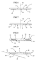
- FIG. 6 a variant is shown in which the layers 30 and 31 extend in the direction of the width of the rapier band 1 to a distance from the row of holes.
- the gripper belt 1 has a profiled wide longitudinal side 20 in the region of the layers 30 and 31 and the lower edge of the base body 22nd
- FIG. 7 a further variant is shown in which a plurality of layers 30, 31, 33 and 34 according to the invention are provided.
- the rapier band 1 shown also has a smooth wide longitudinal side 20.
- the layers 30 and 31 protect the warp threads of the warp thread level 40 from damage, breakage and / or blackening.
- the layers 33 and 34 may be made of the same material as the layers 30 and 31.
- the base body 22 consists for example of a homogeneous material, for example a thermoplastic material in which short carbon fibers are integrated, and of several layers 37 and 38 which contain long fibers within the rapier band 1 preferably in the area the middle part of the rapier band 1 are integrated.
- the base body 22 of the rapier band 1 has a bevel 26 in the vicinity of the layer 30 and a chamfer 27 in the vicinity of the layer 31.
- the layers 30, 31 extend to a small distance from the side edges 23 and 24.
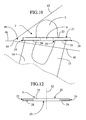
- a gripper belt 1 can also be guided by guide elements 14 and 15 in the shed 41.
- the guide elements 14 and 15 may be of the type as in EP 0 963 469 A1 They may be fixed to the sley 11 in a conventional manner and they may move together with the sley 11.
- the rapier band 1 is guided in the region of the layer 30 by guide elements 14, which are arranged in a first row, while the rapier band 1 is guided in the region of the layer 31 by the guide elements 15, which are arranged in the other row ,
- the material of the layers 30 and 31 must be chosen so that this material is sufficiently resistant to wear during rubbing on such guide elements 14 and 15.
- the layers 30 and 31 may include, for example, a plastic such as a polyamide, in which long and, for example non-abrasive fibers are present, which extend mainly in the longitudinal direction of the rapier band 1.
- Layers 30 and 31 preferably do not contain abrasive fibers such as carbon fibers, but may not contain abrasive fillers. As in FIG. 10 is clarified, the layers 30 and 31 are slightly rounded at the edges 35 and 36, to restrict the action of the layers 30 and 31 on the warp threads.
- a reinforcing rib 16 is fixed to the gripper rapier 3 on the wide longitudinal side 21 in a known manner.
- This reinforcing rib 16 can be attached to both the rapier band 1 and the slave gripper 3 and extends over a certain distance.
- a guide piece 18 is provided, which is arranged in the extension of the rapier band 1 and whose cross section is almost equal to the cross section of the rapier band 1.
- This guide piece 18 can serve as a replaceable wear part.
- This guide piece 18 is made, for example, of the same material as the layers 30, 31, 33 and 34 or of another conventional, non-abrasive material. It is clear that the rapier band 1 can be performed on Gebergreifer 2 in an analogous manner as in FIG. 11 shown gripper belt 1 on the slave gripper. 3
- FIG. 12 is still a variant of a rapier band 1 with a base body 22 and two layers 28 and 29 shown, which are located on the side edges 23 and 24 of the rapier band 1, shown.
- the layers 28 and 29 extend in the longitudinal direction of the rapier band 1 and are located on both wide longitudinal sides 20 and 21 of the rapier band 1.
- the layers 28 and 29 extend in the direction of the width of the rapier band 1 to a distance from the longitudinal center plane 32 of the rapier band 1.
- the layers 28 and 29 are constructed differently than the base body 22, ie the layers 28 and 29 are made of other materials or are composed differently than the base body 22nd
- the rapier band according to the invention may have a base body 22 which contains very abrasive carbon fibers which extend, for example, as far as the outer surface of the rapier band 1.
- a base body 22 which contains very abrasive carbon fibers which extend, for example, as far as the outer surface of the rapier band 1.
Landscapes
- Engineering & Computer Science (AREA)
- Textile Engineering (AREA)
- Looms (AREA)
- Belt Conveyors (AREA)
- Woven Fabrics (AREA)
Description
- Diese Erfindung betrifft ein Greiferband für eine Greiferwebmaschine. Die Erfindung betrifft auch eine Greiferwebmaschine mit einem derartigen Greiferband.
- Bei Greiferwebmaschinen wird ein Schussfaden mit Hilfe wenigstens eines Greifers ergriffen und in ein Webfach hineingezogen. Ein derartiger Greifer ist an einem flexiblen Greiferband befestigt, das über ein Antriebsrad angetrieben wird und das mit Hilfe von Führungselementen sowohl außerhalb des Webfachs als auch innerhalb des Webfachs geführt wird. Um eine stabile Belegung des Greifers im Webfach zu erreichen, wird nach
EP 741 200 A1 EP 741 200 A1 - Aus der
EP 0 352 223 A1 ist ein Greiferband für eine Greiferwebmaschine bekannt, das aus einem durch mehrere strang- und/oder bündelartige Fasergruppen verstärkten Kunststoff hergestellt ist. Das Greiferband ist dabei auf einer der Längsseiten mit einer Schutzschicht aus einem abriebsfesten Material versehen. - Die Erfindung soll ein Greiferband des oben genannten Typs verbessern.
- Diese Aufgabe wird mit dem Patentanspruch 1 dadurch gelöst, dass das Greiferband einen im wesentlichen rechteckigen Querschnitt mit zwei schmalen Längsseiten und zwei breiten Längsseiten besitzt, wobei wenigstens eine der breiten Längsseiten des Greiferbandes nur über einen Teil in Richtung ihrer Breite mit wenigstens einer Schicht versehen ist, die in Abstand zur Längsmittelebene angeordnet ist die bündig mit einer Seitenkante des Grundkörpers und bündig mit der Außenfläche der zugehörigen Längsseite des Grundkörpers verläuft.
- Ein solches Greiferband, bei dem sich der Grundkörper und die mindestens eine Schicht unterschiedlich zusammensetzen, ermöglicht es, dass der Grundkörper aus Materialien zusammengesetzt ist, die ihm eine hohe Festigkeit verleihen, und dass die mindestens eine Schicht aus Materialien zusammengesetzt ist, die dieser eine hohe Verschleißfestigkeit beim Reiben an den Kettfäden und/oder gute Gleiteigenschaften gegenüber Kettfaden verleihen.
- Gemäß einer bevorzugten Ausführungsform enthält das Greiferband eine Lochreihe, die sich in Längsrichtung des Greiferbands erstreckt und an einer der breiten Seiten des Greiferbands angeordnet ist, einen Grundkörper, der sich mindestens im Bereich der Lochreihe befindet, und mindestens eine Schicht, die sich in der Breite des Greiferbands in einem Abstand zu der Lochreihe erstreckt.
- Ein solches Greiferband bietet den Vorteil, dass das Greiferband im Bereich des Grundkörpers mit der Lochreihe als weitgehend homogenes Teil ausgeführt werden kann. Da sich die mindestens eine Schicht nicht im Bereich der Lochreihe im Greiferband befindet, kann sich diese Schicht durch das Eingreifen der Zähne des Antriebsrades in die Löcher des Greiferbands nicht ablösen. Dies bietet außerdem den Vorteil, dass die Zähne des Antriebsrades, die in die Löcher des Greiferbands eingreifen können, über eine große Kontaktfläche hinweg, wodurch der Verschleiß der Zähne und der Löcher gering bleibt und eine lange Lebensdauer erreicht wird. Aus diesem Grund ist das Greiferband für den Einsatz in schnellen Webmaschinen geeignet. Eine derartige große Kontaktfläche in einem oben genannten homogenen Grundkörper kann bei einem erfindungsgemäßen Greiferband durch eine relativ geringe Höhe des Greiferbands erreicht werden, wobei ein solches Greiferband problemlos um eines Antriebsrades gebogen werden kann.
- Gemäß einer bevorzugten Ausführungsform befindet sich die mindestens eine Schicht im Betrieb auf der Seite, die den der Kettfäden zugewandt ist. Indem ein erfindungsgemäßes Greiferband mit mindestens einer Schicht versehen wird, die sich im Betrieb auf der Seite der Kettfäden befindet und die mit den Kettfäden zusammenwirken kann, ergibt sich der Vorteil, dass die Schicht in passender Weise gewählt werden kann, so dass die mindestens eine Schicht nicht oder nur in ziemlich geringem Maße auf die Kettfäden einwirkt. Dadurch kann die mindestens eine Schicht gleichzeitig wenig verschlissen werden. Darüber hinaus wird durch die mindestens eine Schicht vermieden, dass abrasive Verstärkungsfasern des vorzugsweise verstärkten Grundkörpers des Greiferbands mit den Kettfäden zusammenwirken können.
- Gemäß einer bevorzugten Ausführungsform enthält die mindestens eine Schicht keine Kohlenstofffasern. Bei einem herkömmlichen Greiferband, das Kohlenstofffasern enthält, besteht die Gefahr, dass die Kohlenstofffasern auf die Kettfäden einwirken und die Kettfäden auf diese Weise beschädigen oder schwärzen. Diese Schwarzfärbung wird dadurch verursacht, dass sich Kohlenstofffasern aus dem Greiferband lösen und auf die Kettfäden und zwar insbesondere auf das Schlichtemittel oder so genannte "sizing agent", mit dem die Kettfäden ausgerüstet sind, einwirken. Mit einem erfindungsgemäßen Greiferband kann dieses Problem vermieden werden.
- Erfindungsgemäß kann die mindestens eine Schicht aus einem Material, beispielsweise aus dem so genannten Teflon oder PTFE, Polytetrafluorethylen, bestehen, das eventuell Füllstoffe enthält, das eine hohe Verschleißfestigkeit beim Reiben an den Kettfäden und/oder gute Gleiteigenschaften gegenüber den Kettfäden aufweist. Dieses Material muss jedoch nicht notwendigerweise eine hohe Festigkeit aufweisen. Es ist vorzuziehen, dass Grundkörper des Greiferbands eine hohe Festigkeit und Steifigkeit aufweist.
- Gemäß einer bevorzugten Ausführungsform umfasst das Greiferband mindestens eine Lage, die sich in der Breite ab einer Seitenkante des Greiferbands bis zu einem Abstand von der Lochreihe erstreckt. Dadurch erstreckt sich die mindestens eine Schicht mit Sicherheit bis zu der Kante des Greiferbands, die mit den Kettfäden in Berührung kommt.
- Gemäß einer bevorzugten Ausführungsform befindet sich die mindestens eine Schicht an der Längsseite des Greiferbands, die sich gegenüber der Längsseite des Greiferbands befindet, die im Betrieb zum Greifer gerichtet ist. Diese Längsseite, an der sich die mindestens eine Schicht befindet, ist zu den Kettfäden gerichtet.
- Gemäß einer bevorzugten Ausführungsform umfasst das Greiferband an einer Längsseite eine erste Schicht, die sich in Richtung der Breite von der ersten Seitenkante des Greiferbands bis zu einem Abstand von der Lochreihe erstreckt und an dieser Längsseite eine zweite Lage, die sich in der Breite von der anderen Seitenkante des Greiferbands bis zu einem Abstand von der Lochreihe erstreckt. Dies bietet den Vorteil, dass das Greiferband symmetrisch ausgeführt werden kann, und ohne um seine Längsachse verdreht zu werden, um ein Antriebsrad gebogen werden kann.
- Gemäß einer Ausführungsform besteht der Grundkörper aus einem faserverstärkten Teil, das vorzugsweise kurze Kohlenstofffasern enthält.
- Gemäß einer bevorzugten Ausführungsform umfasst das erfindungsgemäße Greiferband an der Seite der mindestens einen Schicht eine glatte Außenfläche in Längsrichtung. Dadurch kann bei einer bestimmten Webmaschine ein herkömmliches Greiferband mit einer glatten Außenfläche in Längsrichtung durch ein erfindungsgemäßes Greiferband ersetzt werden.
- Um die Merkmale der Erfindung zu verdeutlichen, ist die Erfindung anhand der Zeichnung mit Ausführungsbeispielen im Folgenden näher beschrieben.
- Es zeigen:
- Fig. 1
- eine schematische Darstellung einer Greiferwebmaschine mit zwei erfindungsgemäßen Greiferbändern,
- Fig. 2
- einen vergrößerten Querschnitt eines erfindungsgemäßen Greiferbands,
- Fig. 3
- eine Ansicht entlang Pfeil F3 aus
Figur 2 , - Fig. 4
- das Greiferband gemäß
Figur 2 in einer Greiferwebmaschine, - Fig. 5
- eine Variante von
Figur 4 , - Fig. 6 bis 8
- Varianten von
Figur 2 , - Fig. 9 und 10
- eine Variante von
Figur 4 , - Fig. 11
- ein Greiferband mit einem Nehmergreifer und
- Fig. 12
- eine weitere Variante von
Figur 2 . - Die in
Figur 1 dargestellte Greiferwebmaschine umfasst zwei Greiferbänder 1, an denen jeweils ein Greifer und zwar ein Gebergreifer 2 und ein Nehmergreifer 3 befestigt sind. Der Gebergreifer 2 kann einen Schussfaden von einer Seite des Webfachs der Greiferwebmaschine bis zur Mitte des Webfachs bringen, während der Nehmergreifer 3 dort den Schussfaden übernehmen und zur gegenüber liegenden Seite der Greiferwebmaschine bringen kann. Hierzu wird jedes Greiferband 1 von einer Antriebseinheit 4 angetrieben, die jeweils im Bereich eines Seitengestells 5 der Webmaschine angeordnet ist. Jede Antriebseinheit 4 umfasst ein Antriebsrad 6, das mit einem Greiferband 1 zusammenwirkt, um das Greiferband 1 im Webfach zu bewegen. Bei der dargestellten Ausführungsform ist das Greiferband 1 flexibel und kann um das Antriebsrad 6 gebogen werden. Jedes Greiferband 1 wird mit Führungsblöcken 7 in Kontakt mit den Antriebsrädern 6 gehalten. Dabei besitzt jedes Antriebsrad 6 verteilt über den Umfang eine Anzahl von Zähnen 8. Wie in denFiguren 2 und3 dargestellt, besitzt das Greiferband 1 Öffnungen oder Löcher 9, in die die Zähne 8 des Antriebsrades 6 in bekannter Art und Weise eingreifen können. Die Greiferwebmaschine umfasst des weiteren Antriebseinheiten 10 für den Antrieb einer Weblade 11, auf der ein Webblatt 12 vorgesehen ist. Die Weblade 11 ist in den Seitengestellen 5 gelagert. Die Antriebseinheiten 10 werden synchron zu den Antriebseinheiten 4 angetrieben. An den Seitengestellen 5 werden die Greiferbänder 1 gleichzeitig mittels fest angebrachten Führungselementen 13 geführt. - Wie in den
Figuren 2 bis 4 verdeutlicht, umfasst das Greiferband 1 eine Reihe von Öffnungen 9, die sich in Längsrichtung A des Greiferbands 1 erstreckt. Die Öffnungen 9 sind in den Längsflächen oder Längsseiten 20 und 21 des Greiferbands 1 angebracht. Das Greiferband 1 umfasst einen faserverstärkten Grundkörper 22, der sich in Höhe der Reihe von Öffnungen 9 befindet und sich zwischen den Seitenkanten 23 und 24 des Greiferbands 1 erstreckt. Dieser Grundkörper 22 umfasst beispielsweise Verstärkungsfasern mit hoher Festigkeit wie z.B. Kohlenstofffasern, insbesondere kurze Kohlenstofffasern. Solche Kohlenstofffasern sind bekanntlich ziemlich abrasiv, verleihen dem Greiferband 1 jedoch eine hohe Festigkeit. Diese Kohlenstofffasern werden zusammen mit einem Bindemittel, beispielsweise einem thermoplastischen Material, zu einem relativ homogenen Ganzen verbunden, aus dem das Kernstück 22 besteht. Dabei befinden sich die Verstärkungsfasern zwischen dem Bindemittel und bilden zusammen mit dem Bindemittel ein nahezu homogenes Kernstück 22. Das Bindemittel enthält beispielsweise einen thermoplastischen Kunststoff, insbesondere ein Polymer wie z.B. ein Polyamid. - Selbstverständlich kann das Kernstück 22 auch andere Verstärkungsfasern als Kohlenstofffasern wie z.B. Kevlarfasern umfassen. Gemäß einer nicht dargestellten Variante können die Verstärkungsfasern auch in herkömmlicher Weise in Schichten oder als Gewebe wie beispielsweise in
EP 741 200 A1 - Das in den
Figuren 2 bis 4 dargestellte erfindungsgemäße Greiferband 1 besitzt zwei Schichten 30 und 31, die sich in Längsrichtung A des Greiferbands 1 erstrecken. Diese beiden Schichten 30 und 31 befinden sich an der Längsseite 20, d.h. an der breiten Seite oder Längsfläche des einen im wesentlichen flachen, rechteckigen Querschnitt aufweisenden Greiferbands 1, die im Betrieb zur unteren Kettfadenebene 40 eines Webfachs 41 gerichtet ist. Im Betrieb und im dargestellten Beispiel ist dies die untere breite Längsseite 20. Diese Längsseite 20 ist bei der dargestellten Ausführungsform dem Antriebsrad 6 zugewandt, wenn das Greiferband 1 um das Antriebsrad 6 gebogen wird. Die Schichten 30 und 31 sind so angeordnet, dass ein Greiferband 1 mit einer glatten Längsseite 20 im Bereich der Schichten 30 und 31 erzielt wird, d.h. die Schichten 30, 31 verlaufen bündig mit der Außenfläche der breiten Längsseite 20. Diese Längsseite 20 befindet sich auf der der Längsseite 21 des Greiferbands 1 entgegen gesetzten Seite, die im Betrieb gemäß der Darstellung inFigur 4 dem auf dem Greiferband 1 befestigten Nehmergreifer 3 und der oberen Kettfadenebene 42 zugewandt ist. Im Betrieb ist die Längsseite 21 dabei die obere Seite oder Längsfläche des Greiferbands 1. Die untere Kettfadenebene 40 und die obere Kettfadenebene 42 laufen an der Anschlaglinie 43 des Gewebes 46 zusammen. InFigur 4 ist des Weiteren eine Gewebestütze 44 und eine Stütze 45 für die untere Kettfadenebene 40 dargestellt. - Gemäß der Darstellung in
Figur 2 erstreckt sich die Schicht 30 in Richtung der Breite B ausgehend von der Seitenkante 23 bis zu einem Abstand X von der Lochreihe 9, während sich die Schicht 31 in Richtung der Breite B ausgehend von der Seitenkante 24 bis zu einem Abstand Y von der Lochreihe 9 erstreckt. Die beiden Schichten 30 und 31 liegen symmetrisch zur Längsmittelachse 32 und erstrecken sich in Richtung der Breite B des Greiferbands 1 bis zu einem Abstand von der Längsmittelachse 32 des Greiferbands 1. Die in Längsrichtung verlaufenden Schichten 30, 31 erstrecken sich somit nun über einen Teil der Längsseite 20 des Greiferbandes 1. Dies ist vorteilhaft beim Biegen des Greiferbands 1 um ein Antriebsrad 6 und beim Transport des Greiferbands 1 durch das Webfach 41. - Die Schichten 30 und 31 enthalten beispielsweise ein Material, z.B. einen thermoplastischen Kunststoff, das beim Reiben an den Kettfäden eine hohe Verschleißfestigkeit aufweist und das gegenüber den Kettfäden gute Gleiteigenschaften besitzt. Dieses Material muss nicht notwendigerweise eine hohe Festigkeit haben. Vorzugsweise wird als Material Teflon oder PTFE verwendet, das die oben genannten Eigenschaften besitzt. Dieses Teflon oder PTFE kann auch nicht abrasive Füllstoffe wie beispielsweise Bronze enthalten. Das Hinzufügen von Bronze als Füllstoff erhöht nicht nur die Wärmeleitfähigkeit von Teflon oder PTFE, sondern verbessert auch die Verschleißfestigkeit gegenüber den Kettfäden und die Gleiteigenschaften gegenüber den Kettfäden.
- Gemäß der Darstellung in
Figur 4 befinden sich die Schichten 30 und 31 im Betrieb an der unteren Kettfadenebene 40. Bei der Bewegung des Greiferbands 1 durch das Webfach 41 können die Kettfäden der unteren Kettfadenebene 40 gemäß der Darstellung inFigur 4 mit der Schicht 30 und/oder mit der Schicht 31 in Berührung kommen. Dabei kann durch die Schichten 30 und 31 vermieden werden, dass Kettfäden insbesondere an den Kanten 35 und 36 des Greiferbands 1 dem Grundkörper 22 in Berührung kommen können. Dadurch kann vermieden werden, dass die Kettfäden beschädigt oder geschwärzt werden. Dabei ist es vor allem wichtig, dass die Kettfäden mit dem Bereich der unteren Kanten 35 und 36 des Greiferbands 1 mit den Schichten 30 und 31 in Kontakt geraten und nicht mit dem Grundkörper 22 des Greiferbands 1, das abrasive Verstärkungsfasern wie z.B. Kohlenstofffasern enthält. - Bei der Ausführungsform von
Figur 5 besitzt das Greiferband 1 nur eine Schicht 30, die sich in Richtung der Breite B ausgehend von einer Seitenkante 23 des Greiferbands 1 bis zu einem Abstand X von der Lochreihe 9 erstreckt. Dabei hat das Greiferband 1 an der Schicht 30 ebenfalls eine glatte Seite 20. Da die Kettfäden der Kettfadenebene 40 normalerweise meistens an der Seitenkante 23, die sich an der Anschlaglinie 43 befindet, insbesondere im Bereich der Kante 35 des Greiferbands 1 auf das Greiferband 1 einwirken, wird in diesem Fall nur eine einzige erfindungsgemäße Schicht 30 vorgesehen, wobei diese Schicht 30 vorzugsweise an der oben genannten Kante 35 angebracht wird. - In
Figur 6 ist eine Variante dargestellt, bei der sich die Schichten 30 und 31 in Richtung der Breite des Greiferbands 1 bis zu einem Abstand von der Lochreihe erstrecken. Dabei besitzt das Greiferband 1 eine profilierte breite Längsseite 20 im Bereich der Schichten 30 und 31 und der unteren Kante des Grundkörpers 22. - In
Figur 7 ist eine weitere Variante dargestellt, bei der mehrere erfindungsgemäße Schichten 30, 31, 33 und 34 vorgesehen sind. Das dargestellte Greiferband 1 weist ebenfalls eine glatte breite Längsseite 20 auf. Die Schichten 30 und 31 schützen hierbei die Kettfäden der Kettfadenebene 40 vor Beschädigung, Bruch und/oder Schwarzfärbung. Die Schichten 33 und 34 können aus dem gleichen Material wie die Schichten 30 und 31 bestehen. - In
Figur 8 ist eine Variante dargestellt, bei der der Grundkörper 22 beispielsweise aus einem homogenen Material besteht, z.B. einem thermoplastischen Kunststoff, in den kurze Kohlenstofffasern integriert sind, und aus mehreren Schichten 37 und 38, die lange Fasern enthalten, die innerhalb des Greiferbands 1 vorzugsweise im Bereich des Mittelteils des Greiferbands 1 integriert sind. - Bei der Ausführungsform von
Figur 9 besitzt der Grundkörper 22 des Greiferbands 1 in der Nähe der Schicht 30 eine Abschrägung 26 und in der Nähe der Schicht 31 eine Abschrägung 27. Die Schichten 30, 31 erstrecken sich bis zu einem geringen Abstand von den Seitenkanten 23 und 24. Durch die Abschrägungen 26 und 27 sind die Kettfäden der Kettfadenebene 40 vor Beschädigung, Bruch und/oder Schwarzfärbung geschützt, die von dem Grundkörper 22 sonst verursacht werden könnten. - Gemäß der Darstellung in
Figur 10 kann ein Greiferband 1 auch durch Führungselemente 14 und 15 im Webfach 41 geführt werden. Die Führungselemente 14 und 15 können von der Art wie inEP 0 963 469 A1 beschrieben sein, sie können in herkömmlicher Weise an der Weblade 11 befestigt sein und sie können sich zusammen mit der Weblade 11 bewegen. Bei dieser Ausführungsform wird das Greiferband 1 im Bereich der Schicht 30 durch Führungselemente 14, die in einer ersten Reihe angeordnet sind, geführt, während das Greiferband 1 im Bereich der Schicht 31 durch die Führungselemente 15, die in der anderen Reihe angeordnet sind, geführt wird. Selbstverständlich muss das Material der Schichten 30 und 31 hierbei so gewählt werden, dass dieses Material beim Reiben an solchen Führungselementen 14 und 15 ausreichend verschleißfest ist. Dabei können die Schichten 30 und 31 beispielsweise einen Kunststoff wie z.B. ein Polyamid enthalten, in dem lange und beispielsweise nicht abrasive Fasern enthalten sind, die sich hauptsächlich in der Längsrichtung des Greiferbands 1 erstrecken. Die Schichten 30 und 31 enthalten vorzugsweise keine abrasiven Fasern wie z.B. Kohlenstofffasern, können jedoch nicht abrasive Füllstoffe enthalten. Wie inFigur 10 verdeutlicht ist, sind die Schichten 30 und 31 an den Kanten 35 und 36 etwas abgerundet, um die Einwirkung der Schichten 30 und 31 auf die Kettfäden einzuschränken. - Wie in
Figur 11 verdeutlicht ist, wird am Nehmergreifer 3 an der breiten Längsseite 21 in bekannter Weise eine Verstärkungsrippe 16 befestigt. Diese Verstärkungsrippe 16 kann sowohl am Greiferband 1 als auch am Nehmergreifer 3 befestigt werden und erstreckt sich über eine bestimmte Strecke. Am vorderen Teil 17 des Greiferbands 1 im Bereich des Nehmergreifers 3 ist ein Führungsstück 18 vorgesehen, das in der Verlängerung des Greiferbands 1 angeordnet und dessen Querschnitt nahezu gleich dem Querschnitt des Greiferbands 1 ist. Dieses Führungsstück 18 kann als austauschbares Verschleißteil dienen. Dieses Führungsstück 18 wird beispielsweise aus dem gleichen Material hergestellt wie die Schichten 30, 31, 33 und 34 oder aus einem anderen herkömmlichen, nicht abrasiven Material. Es ist klar, dass das Greiferband 1 am Gebergreifer 2 in analoger Weise ausgeführt werden kann wie das inFigur 11 dargestellte Greiferband 1 am Nehmergreifer 3. - In
Figur 12 ist noch eine Variante eines Greiferbands 1 mit einem Grundkörper 22 und zwei Schichten 28 und 29 dargestellt, die sich an den Seitenkanten 23 und 24 des Greiferbands 1 befinden, dargestellt. Die Schichten 28 und 29 erstrecken sich in Längsrichtung des Greiferbands 1 und befinden sich an beiden breiten Längsseite 20 und 21 des Greiferbands 1. Die Schichten 28 und 29 erstrecken sich in Richtung der Breite des Greiferbands 1 bis zu einem Abstand von der Längsmittelebene 32 des Greiferbands 1. Die Schichten 28 und 29 sind anders aufgebaut als der Grundkörper 22, d.h. die Schichten 28 und 29 sind aus anderen Materialien oder sind anders zusammengesetzt als der Grundkörper 22. - Das erfindungsgemäße Greiferband kann einen Grundkörper 22 aufweisen, der sehr abrasive Kohlenstofffasern enthält, die sich beispielsweise bis zur Außenfläche des Greiferbands 1 erstrecken. Durch das Vorsehen der Schichten 30 und 31 wird die Gefahr der Beschädigung oder des Bruchs von Kettfäden durch Kontakt mit dem Greiferband 1 praktisch ausgeschlossen. Gleichzeitig wird die Gefahr einer Schwarzfärbung der Kettfäden durch sich ablösende Kohlenstofffasern praktisch ausgeschlossen.
Das erfindungsgemäße Greiferband 1 und die erfindungsgemäße Greiferwebmaschine beschränken sich selbstverständlich nicht auf die als Beispiel beschriebenen und in den Figuren dargestellten Ausführungsformen, sondern können im Rahmen des Schutzumfangs der Ansprüche entsprechend anderen Formen und Abmessungen ausgeführt werden. Im Rahmen des Schutzumfangs der Ansprüche können das Greiferband und die Greiferwebmaschine auch entsprechend verschiedenen Varianten und in verschiedenen Kombinationen der dargestellten Ausführungsformen ausgeführt werden.
Claims (8)
- Greiferband (1) für eine Greiferwebmaschine, das einen Grundkörper (22) aus vorzugsweise verstärktem Kunststoff aufweist, der auf wenigstens einer der Längsseiten mit einer in Längsrichtung (A) verlaufenden Schicht (28, 29, 30, 31, 33, 34) versehen ist, die aus einem Material mit einer Zusammensetzung besteht, die von der Zusammensetzung des Materials des Grundkörpers (22) verschieden ist, dadurch gekennzeichnet, dass das Greiferband (1) einen im wesentlichen rechteckigen Querschnitt mit zwei schmalen Längsseiten und zwei breiten Längsseiten (20, 21) besitzt, wobei wenigstens eine der breiten Längsseiten (20, 21) nur über einen Teil in Richtung der Breite (B) mit wenigstens einer Schicht (28, 29, 30, 31, 33, 34) versehen ist, die in Abstand zur Längsmittelebene (33) angeordnet ist, die bündig mit einer Seitenkante (23, 24) des Grundkörpers (22) und bündig mit der Außenfläche der zugehörigen Längsseite (20, 21) des Grundkörpers (22) verläuft.
- Greiferband nach Anspruch 1, dadurch gekennzeichnet, dass der Grundkörper (22) mit einer in Längsrichtung (A) verlaufenden Lochreihe (9) versehen ist und dass die sich auf der Längsseite (20, 21) des Grundkörpers (22) befindende Schicht (28, 29, 30, 31, 33, 34) einen Abstand (X, Y) zu der Lochreihe (9) einhält.
- Greiferband nach Anspruch 1 oder 2, dadurch gekennzeichnet, dass die Schicht (28, 29, 30, 31, 33, 34) in einem Bereich angebracht ist, der Kettfäden (40) zugeordnet ist.
- Greiferband nach einem der Ansprüche 1 bis 3, dadurch gekennzeichnet, dass die Schicht (28, 29, 30, 31, 33, 34) frei von Kohlenstofffasern ist.
- Greiferband nach einem der Ansprüche 1 bis 4, dadurch gekennzeichnet, dass die Schicht (28, 29, 30, 31, 33, 34) aus einem Material, beispielsweise Polytetrafluorethylen, besteht, das Gleitfähigkeit bezüglich Kettfäden besitzt.
- Greiferband nach einem der Ansprüche 1 bis 5, dadurch gekennzeichnet, dass der Grundkörper (22) Kohlenstofffasern enthält.
- Greiferband nach einem der Ansprüche 1 bis 6, dadurch gekennzeichnet, dass beidseits der Lochreihe (9) jeweils ein Abschnitt der Schicht (28, 29, 30, 31, 33, 34) vorgesehen ist.
- Greiferwebmaschine, dadurch gekennzeichnet, dass sie mit wenigstens einem Greiferband (1) nach einem der Ansprüche 1 bis 7 ausgerüstet ist.
Applications Claiming Priority (2)
| Application Number | Priority Date | Filing Date | Title |
|---|---|---|---|
| BE2004/0174A BE1015971A6 (nl) | 2004-04-05 | 2004-04-05 | Grijperband voor een grijperweefmachine en grijperweefmachine. |
| BE200400174 | 2004-04-05 |
Publications (3)
| Publication Number | Publication Date |
|---|---|
| EP1586683A2 EP1586683A2 (de) | 2005-10-19 |
| EP1586683A3 EP1586683A3 (de) | 2006-05-17 |
| EP1586683B1 true EP1586683B1 (de) | 2011-07-06 |
Family
ID=34934541
Family Applications (1)
| Application Number | Title | Priority Date | Filing Date |
|---|---|---|---|
| EP05006700A Expired - Lifetime EP1586683B1 (de) | 2004-04-05 | 2005-03-26 | Greiferband für eine Greiferwebmaschine und Greiferwebmaschine |
Country Status (3)
| Country | Link |
|---|---|
| EP (1) | EP1586683B1 (de) |
| AT (1) | ATE515588T1 (de) |
| BE (1) | BE1015971A6 (de) |
Families Citing this family (3)
| Publication number | Priority date | Publication date | Assignee | Title |
|---|---|---|---|---|
| BE1019316A3 (nl) | 2010-04-29 | 2012-06-05 | Picanol Nv | Lans en grijperweefmachine. |
| BE1024494B1 (nl) * | 2016-08-11 | 2018-03-12 | Picanol Naamloze Vennootschap | Grijperband en grijpereenheid voor een grijperweefmachine |
| EP4212658B1 (de) | 2022-01-13 | 2025-07-23 | Picanol | Vorrichtung zum einstellen einer position einer stationären führung |
Family Cites Families (5)
| Publication number | Priority date | Publication date | Assignee | Title |
|---|---|---|---|---|
| EP0352223B1 (de) | 1988-07-22 | 1993-02-03 | GebràDer Sulzer Aktiengesellschaft | Schusseintragsvorrichtung einer Greiferwebmaschine |
| FI83791C (fi) * | 1989-08-24 | 1991-08-26 | Neste Oy | Slitstarkt band och foerfarande foer framstaellning av detta. |
| BE1009355A6 (nl) | 1995-05-04 | 1997-02-04 | Picanol Nv | Grijperweefmachine met een grijper en een grijperband. |
| EP1074646B1 (de) * | 1999-07-29 | 2003-03-19 | Wu-Chen Chuang | Webmaschine mit magnetischer Schütze |
| KR20010076481A (ko) * | 2000-01-26 | 2001-08-16 | 이규건 | 직기의 레피어 밴드 |
-
2004
- 2004-04-05 BE BE2004/0174A patent/BE1015971A6/nl not_active IP Right Cessation
-
2005
- 2005-03-26 EP EP05006700A patent/EP1586683B1/de not_active Expired - Lifetime
- 2005-03-26 AT AT05006700T patent/ATE515588T1/de active
Also Published As
| Publication number | Publication date |
|---|---|
| ATE515588T1 (de) | 2011-07-15 |
| EP1586683A3 (de) | 2006-05-17 |
| EP1586683A2 (de) | 2005-10-19 |
| BE1015971A6 (nl) | 2005-12-06 |
Similar Documents
| Publication | Publication Date | Title |
|---|---|---|
| EP2659039B1 (de) | Sicherheitsgurtband für ein sicherheitsgurtsystem | |
| DE2145459C3 (de) | Kratzenbeschlag für den Deckel von Karden | |
| AT407377B (de) | Handlauf | |
| EP1908863B1 (de) | Weblitze für Jacquardwebmaschine | |
| EP0079431A1 (de) | Einlagiges Papiermaschinensieb | |
| EP0352223B1 (de) | Schusseintragsvorrichtung einer Greiferwebmaschine | |
| CH642407A5 (de) | Webelitze. | |
| EP0763623B1 (de) | Papiermaschienenband | |
| WO1998044180A1 (de) | Greiferwebmaschine | |
| DE10029470A1 (de) | Zahnriemen | |
| EP1586683A2 (de) | Greiferband für eine Greiferwebmaschine und Greiferwebmaschine | |
| DE102005033175B3 (de) | Weblitze, insbesondere für schnell laufende Webmaschinen | |
| DE19822265B4 (de) | Offenend-Spinnrotor und Verfahren zu seiner Herstellung | |
| EP1020548B1 (de) | Kratzenbelag für deckel einer Karde | |
| DE3241153C2 (de) | Einschließ- und Abschlagplatine für Wirk- oder Strickmaschinen | |
| EP0741200B1 (de) | Greifervorrichtung für eine Greiferwebmaschine | |
| CH652692A5 (de) | Kantenschutzeinrichtung an einem gliederriemen. | |
| AT402516B (de) | Gewebeband-einrichtung | |
| DE69211392T2 (de) | Mitnehmergreifer für schützenlose Webmaschinen, insbesondere zum Weben von synthetischen Fäden | |
| EP4467700B1 (de) | Textilwerkzeug, textilwerkzeugverbund und textilmaschine zur herstellung eines textilen flächengebildes | |
| EP0964183B1 (de) | Riemen zur Herstellung eines Wattewickels | |
| DE102022117301B3 (de) | Gewebeband | |
| DE202020102917U1 (de) | Breithalter zur Kontrolle der Spannung eines Gewebes in einer Textilmaschine | |
| EP1793026B1 (de) | Schiffchenführungsplatte für Stickmaschinen | |
| DE602004001487T2 (de) | Vorrichtung zum Befestigen und Führen einer oder mehrerer Flaschenzugkordeln einer Jacquardmaschine |
Legal Events
| Date | Code | Title | Description |
|---|---|---|---|
| PUAI | Public reference made under article 153(3) epc to a published international application that has entered the european phase |
Free format text: ORIGINAL CODE: 0009012 |
|
| AK | Designated contracting states |
Kind code of ref document: A2 Designated state(s): AT BE BG CH CY CZ DE DK EE ES FI FR GB GR HU IE IS IT LI LT LU MC NL PL PT RO SE SI SK TR |
|
| AX | Request for extension of the european patent |
Extension state: AL BA HR LV MK YU |
|
| PUAL | Search report despatched |
Free format text: ORIGINAL CODE: 0009013 |
|
| AK | Designated contracting states |
Kind code of ref document: A3 Designated state(s): AT BE BG CH CY CZ DE DK EE ES FI FR GB GR HU IE IS IT LI LT LU MC NL PL PT RO SE SI SK TR |
|
| AX | Request for extension of the european patent |
Extension state: AL BA HR LV MK YU |
|
| 17P | Request for examination filed |
Effective date: 20060627 |
|
| AKX | Designation fees paid |
Designated state(s): AT BE BG CH CY CZ DE DK EE ES FI FR GB GR HU IE IS IT LI LT LU MC NL PL PT RO SE SI SK TR |
|
| 17Q | First examination report despatched |
Effective date: 20081215 |
|
| RAP1 | Party data changed (applicant data changed or rights of an application transferred) |
Owner name: PICANOL |
|
| GRAP | Despatch of communication of intention to grant a patent |
Free format text: ORIGINAL CODE: EPIDOSNIGR1 |
|
| GRAS | Grant fee paid |
Free format text: ORIGINAL CODE: EPIDOSNIGR3 |
|
| GRAA | (expected) grant |
Free format text: ORIGINAL CODE: 0009210 |
|
| AK | Designated contracting states |
Kind code of ref document: B1 Designated state(s): AT BE BG CH CY CZ DE DK EE ES FI FR GB GR HU IE IS IT LI LT LU MC NL PL PT RO SE SI SK TR |
|
| REG | Reference to a national code |
Ref country code: GB Ref legal event code: FG4D Free format text: NOT ENGLISH |
|
| REG | Reference to a national code |
Ref country code: CH Ref legal event code: EP |
|
| REG | Reference to a national code |
Ref country code: IE Ref legal event code: FG4D Free format text: LANGUAGE OF EP DOCUMENT: GERMAN |
|
| REG | Reference to a national code |
Ref country code: DE Ref legal event code: R096 Ref document number: 502005011571 Country of ref document: DE Effective date: 20110901 |
|
| REG | Reference to a national code |
Ref country code: NL Ref legal event code: VDEP Effective date: 20110706 |
|
| PG25 | Lapsed in a contracting state [announced via postgrant information from national office to epo] |
Ref country code: SI Free format text: LAPSE BECAUSE OF FAILURE TO SUBMIT A TRANSLATION OF THE DESCRIPTION OR TO PAY THE FEE WITHIN THE PRESCRIBED TIME-LIMIT Effective date: 20110706 |
|
| PG25 | Lapsed in a contracting state [announced via postgrant information from national office to epo] |
Ref country code: IS Free format text: LAPSE BECAUSE OF FAILURE TO SUBMIT A TRANSLATION OF THE DESCRIPTION OR TO PAY THE FEE WITHIN THE PRESCRIBED TIME-LIMIT Effective date: 20111106 Ref country code: NL Free format text: LAPSE BECAUSE OF FAILURE TO SUBMIT A TRANSLATION OF THE DESCRIPTION OR TO PAY THE FEE WITHIN THE PRESCRIBED TIME-LIMIT Effective date: 20110706 Ref country code: PT Free format text: LAPSE BECAUSE OF FAILURE TO SUBMIT A TRANSLATION OF THE DESCRIPTION OR TO PAY THE FEE WITHIN THE PRESCRIBED TIME-LIMIT Effective date: 20111107 Ref country code: FI Free format text: LAPSE BECAUSE OF FAILURE TO SUBMIT A TRANSLATION OF THE DESCRIPTION OR TO PAY THE FEE WITHIN THE PRESCRIBED TIME-LIMIT Effective date: 20110706 Ref country code: SE Free format text: LAPSE BECAUSE OF FAILURE TO SUBMIT A TRANSLATION OF THE DESCRIPTION OR TO PAY THE FEE WITHIN THE PRESCRIBED TIME-LIMIT Effective date: 20110706 Ref country code: LT Free format text: LAPSE BECAUSE OF FAILURE TO SUBMIT A TRANSLATION OF THE DESCRIPTION OR TO PAY THE FEE WITHIN THE PRESCRIBED TIME-LIMIT Effective date: 20110706 |
|
| REG | Reference to a national code |
Ref country code: IE Ref legal event code: FD4D |
|
| PG25 | Lapsed in a contracting state [announced via postgrant information from national office to epo] |
Ref country code: CY Free format text: LAPSE BECAUSE OF FAILURE TO SUBMIT A TRANSLATION OF THE DESCRIPTION OR TO PAY THE FEE WITHIN THE PRESCRIBED TIME-LIMIT Effective date: 20110706 Ref country code: GR Free format text: LAPSE BECAUSE OF FAILURE TO SUBMIT A TRANSLATION OF THE DESCRIPTION OR TO PAY THE FEE WITHIN THE PRESCRIBED TIME-LIMIT Effective date: 20111007 Ref country code: PL Free format text: LAPSE BECAUSE OF FAILURE TO SUBMIT A TRANSLATION OF THE DESCRIPTION OR TO PAY THE FEE WITHIN THE PRESCRIBED TIME-LIMIT Effective date: 20110706 |
|
| PG25 | Lapsed in a contracting state [announced via postgrant information from national office to epo] |
Ref country code: IE Free format text: LAPSE BECAUSE OF FAILURE TO SUBMIT A TRANSLATION OF THE DESCRIPTION OR TO PAY THE FEE WITHIN THE PRESCRIBED TIME-LIMIT Effective date: 20110706 Ref country code: CZ Free format text: LAPSE BECAUSE OF FAILURE TO SUBMIT A TRANSLATION OF THE DESCRIPTION OR TO PAY THE FEE WITHIN THE PRESCRIBED TIME-LIMIT Effective date: 20110706 Ref country code: SK Free format text: LAPSE BECAUSE OF FAILURE TO SUBMIT A TRANSLATION OF THE DESCRIPTION OR TO PAY THE FEE WITHIN THE PRESCRIBED TIME-LIMIT Effective date: 20110706 |
|
| PLBE | No opposition filed within time limit |
Free format text: ORIGINAL CODE: 0009261 |
|
| STAA | Information on the status of an ep patent application or granted ep patent |
Free format text: STATUS: NO OPPOSITION FILED WITHIN TIME LIMIT |
|
| PG25 | Lapsed in a contracting state [announced via postgrant information from national office to epo] |
Ref country code: EE Free format text: LAPSE BECAUSE OF FAILURE TO SUBMIT A TRANSLATION OF THE DESCRIPTION OR TO PAY THE FEE WITHIN THE PRESCRIBED TIME-LIMIT Effective date: 20110706 Ref country code: RO Free format text: LAPSE BECAUSE OF FAILURE TO SUBMIT A TRANSLATION OF THE DESCRIPTION OR TO PAY THE FEE WITHIN THE PRESCRIBED TIME-LIMIT Effective date: 20110706 |
|
| 26N | No opposition filed |
Effective date: 20120411 |
|
| PG25 | Lapsed in a contracting state [announced via postgrant information from national office to epo] |
Ref country code: DK Free format text: LAPSE BECAUSE OF FAILURE TO SUBMIT A TRANSLATION OF THE DESCRIPTION OR TO PAY THE FEE WITHIN THE PRESCRIBED TIME-LIMIT Effective date: 20110706 |
|
| REG | Reference to a national code |
Ref country code: DE Ref legal event code: R097 Ref document number: 502005011571 Country of ref document: DE Effective date: 20120411 |
|
| PG25 | Lapsed in a contracting state [announced via postgrant information from national office to epo] |
Ref country code: MC Free format text: LAPSE BECAUSE OF NON-PAYMENT OF DUE FEES Effective date: 20120331 |
|
| REG | Reference to a national code |
Ref country code: CH Ref legal event code: PL |
|
| GBPC | Gb: european patent ceased through non-payment of renewal fee |
Effective date: 20120326 |
|
| REG | Reference to a national code |
Ref country code: FR Ref legal event code: ST Effective date: 20121130 |
|
| PG25 | Lapsed in a contracting state [announced via postgrant information from national office to epo] |
Ref country code: FR Free format text: LAPSE BECAUSE OF NON-PAYMENT OF DUE FEES Effective date: 20120402 Ref country code: LI Free format text: LAPSE BECAUSE OF NON-PAYMENT OF DUE FEES Effective date: 20120331 Ref country code: GB Free format text: LAPSE BECAUSE OF NON-PAYMENT OF DUE FEES Effective date: 20120326 Ref country code: CH Free format text: LAPSE BECAUSE OF NON-PAYMENT OF DUE FEES Effective date: 20120331 |
|
| PG25 | Lapsed in a contracting state [announced via postgrant information from national office to epo] |
Ref country code: ES Free format text: LAPSE BECAUSE OF FAILURE TO SUBMIT A TRANSLATION OF THE DESCRIPTION OR TO PAY THE FEE WITHIN THE PRESCRIBED TIME-LIMIT Effective date: 20111017 |
|
| REG | Reference to a national code |
Ref country code: AT Ref legal event code: MM01 Ref document number: 515588 Country of ref document: AT Kind code of ref document: T Effective date: 20120326 |
|
| PG25 | Lapsed in a contracting state [announced via postgrant information from national office to epo] |
Ref country code: BG Free format text: LAPSE BECAUSE OF FAILURE TO SUBMIT A TRANSLATION OF THE DESCRIPTION OR TO PAY THE FEE WITHIN THE PRESCRIBED TIME-LIMIT Effective date: 20111006 |
|
| PG25 | Lapsed in a contracting state [announced via postgrant information from national office to epo] |
Ref country code: AT Free format text: LAPSE BECAUSE OF NON-PAYMENT OF DUE FEES Effective date: 20120326 |
|
| PG25 | Lapsed in a contracting state [announced via postgrant information from national office to epo] |
Ref country code: TR Free format text: LAPSE BECAUSE OF FAILURE TO SUBMIT A TRANSLATION OF THE DESCRIPTION OR TO PAY THE FEE WITHIN THE PRESCRIBED TIME-LIMIT Effective date: 20110706 |
|
| PG25 | Lapsed in a contracting state [announced via postgrant information from national office to epo] |
Ref country code: LU Free format text: LAPSE BECAUSE OF NON-PAYMENT OF DUE FEES Effective date: 20120326 |
|
| PG25 | Lapsed in a contracting state [announced via postgrant information from national office to epo] |
Ref country code: HU Free format text: LAPSE BECAUSE OF FAILURE TO SUBMIT A TRANSLATION OF THE DESCRIPTION OR TO PAY THE FEE WITHIN THE PRESCRIBED TIME-LIMIT Effective date: 20050326 |
|
| PGFP | Annual fee paid to national office [announced via postgrant information from national office to epo] |
Ref country code: NL Payment date: 20190115 Year of fee payment: 8 |
|
| REG | Reference to a national code |
Ref country code: DE Ref legal event code: R119 Ref document number: 502005011571 Country of ref document: DE |
|
| PG25 | Lapsed in a contracting state [announced via postgrant information from national office to epo] |
Ref country code: DE Free format text: LAPSE BECAUSE OF NON-PAYMENT OF DUE FEES Effective date: 20201001 |
|
| PGFP | Annual fee paid to national office [announced via postgrant information from national office to epo] |
Ref country code: IT Payment date: 20220331 Year of fee payment: 18 |
|
| PGFP | Annual fee paid to national office [announced via postgrant information from national office to epo] |
Ref country code: BE Payment date: 20230123 Year of fee payment: 19 |
|
| P01 | Opt-out of the competence of the unified patent court (upc) registered |
Effective date: 20230517 |
|
| PG25 | Lapsed in a contracting state [announced via postgrant information from national office to epo] |
Ref country code: IT Free format text: LAPSE BECAUSE OF NON-PAYMENT OF DUE FEES Effective date: 20230326 |
|
| REG | Reference to a national code |
Ref country code: BE Ref legal event code: MM Effective date: 20240331 |
|
| PG25 | Lapsed in a contracting state [announced via postgrant information from national office to epo] |
Ref country code: BE Free format text: LAPSE BECAUSE OF NON-PAYMENT OF DUE FEES Effective date: 20240331 |
|
| PG25 | Lapsed in a contracting state [announced via postgrant information from national office to epo] |
Ref country code: BE Free format text: LAPSE BECAUSE OF NON-PAYMENT OF DUE FEES Effective date: 20240331 |