EP1586470A1 - Anhängerkupplung - Google Patents
Anhängerkupplung Download PDFInfo
- Publication number
- EP1586470A1 EP1586470A1 EP05005545A EP05005545A EP1586470A1 EP 1586470 A1 EP1586470 A1 EP 1586470A1 EP 05005545 A EP05005545 A EP 05005545A EP 05005545 A EP05005545 A EP 05005545A EP 1586470 A1 EP1586470 A1 EP 1586470A1
- Authority
- EP
- European Patent Office
- Prior art keywords
- housing
- drehachsglied
- coupling arm
- drehachsgliedes
- cylinder
- Prior art date
- Legal status (The legal status is an assumption and is not a legal conclusion. Google has not performed a legal analysis and makes no representation as to the accuracy of the status listed.)
- Granted
Links
Images






Classifications
-
- B—PERFORMING OPERATIONS; TRANSPORTING
- B60—VEHICLES IN GENERAL
- B60D—VEHICLE CONNECTIONS
- B60D1/00—Traction couplings; Hitches; Draw-gear; Towing devices
- B60D1/24—Traction couplings; Hitches; Draw-gear; Towing devices characterised by arrangements for particular functions
- B60D1/246—Traction couplings; Hitches; Draw-gear; Towing devices characterised by arrangements for particular functions for actuating the hitch by powered means
-
- B—PERFORMING OPERATIONS; TRANSPORTING
- B60—VEHICLES IN GENERAL
- B60D—VEHICLE CONNECTIONS
- B60D1/00—Traction couplings; Hitches; Draw-gear; Towing devices
- B60D1/01—Traction couplings or hitches characterised by their type
- B60D1/06—Ball-and-socket hitches
-
- B—PERFORMING OPERATIONS; TRANSPORTING
- B60—VEHICLES IN GENERAL
- B60D—VEHICLE CONNECTIONS
- B60D1/00—Traction couplings; Hitches; Draw-gear; Towing devices
- B60D1/48—Traction couplings; Hitches; Draw-gear; Towing devices characterised by the mounting
- B60D1/54—Traction couplings; Hitches; Draw-gear; Towing devices characterised by the mounting collapsible or retractable when not in use, e.g. hide-away hitches
Definitions
- the invention relates to a device for lowering and pivoting a Kupptungsarmes in a towing hitch for motor vehicles, in which one provided with a ball Clutch arm from a non-visible from outside the vehicle rest position in a suitable operating position for attaching a trailer motor or manually driven is moved.
- a motor-driven To create trailer hitch which is particularly simple and inexpensive to manufacture. This is achieved in that in the hitch according to the invention no pivot bearing, Locking devices or other components with high manufacturing accuracy for Application, but in which the moving parts within a housing shifted an inclined plane and without using a pivot bearing via a slotted guide transported into the position of use and there by a spindle on the principle of Vices are clamped. Due to the angle of the inclined plane is the Drop height of the ball arm structurally adapted to the respective vehicle.
- An exemplary embodiment of the trailer coupling according to the invention consists of a trough-shaped housing (1) with the side walls (2,3), the rear housing wall (4), the front housing wall (5) and the housing bottom (6) with the slot (7).
- the in the housing (1) located part of the ball arm (9) is designed as Drehachsglied (10).
- the Drehachsglied (10) has in the lower part of a cylindrical shape whose diameter is greater than the inside width of the slot (7).
- the upper part of the Drehachsgliedes (10) is asymmetrical and is described in Fig. 5 in more detail.
- an annular groove (19) is arranged, in which a linkage (17) of the linear drive (16) engages.
- the linear drive (16) is pivotally mounted on the housing rear wall (4) in the bearing (23).
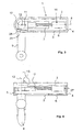
- Fig. 1 shows the trailer hitch in non-use position in a plan view
- Fig. 2 in a side view.
- the linear drive (16) is completely retracted
- the ball arm (9) is retracted in the slot (7) in the direction of the housing rear wall (4).
- the ball arm (9) is parallel to the longitudinal axis (8).
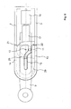
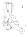
- Fig. 3 shows the hitch in the position of use in a plan view
- Fig. 4 in a Side view.
- the scenery (14) is not shown here to the position of the Drchachsgliedes in to show the position of use.
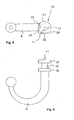
- Fig. 5 shows the Kugetarm (9) with the Drchachsglied (10) in a plan view
- Fig. 6 in a side view.
- the Drehachsglied (10) consists of a lower cylindrical portion (18) and an upper part, which is composed of a semi-cylindrical part (21), and a semi-rectangular part with the straight surfaces (22,23,24).
- a part of the side surface (23) is designed as a wedge surface (28), which corresponds in the position of use with a wedge surface (29) on the housing (1).
- Between the lower and upper part of an annular groove (19) is arranged, on which the linear drive (16) engages with the articulation (17).
- Fig. 7 shows the connection between the ball arm (9) and linear drive (16) in an exploded view.
- the articulation (17) which may be part of a threaded sleeve of a spindle drive, for example, is located on the the Drehachsglied (10) side facing a part-circular bearing surface (25) whose radius corresponds to the radius of the annular groove (19).
- a U-shaped bearing surface (26) which may for example be designed as a U-shaped metal strip, comprises the ball arm (9) in the annular groove (19) and forms when merging both parts in the direction of arrows A, B with the bearing surface (25) circular bearing in which the ball arm (9) can rotate about the pivot axis (12).
- the connection between the bearing parts (25,26) is not shown here in detail, it can be realized for example by a Schrauh- or rivet.
- the ball arm (9) is in the non-use position.
- the pen (11) still has not intervened in the slot.
- the straight surface (22) and the semi-cylindrical Part (21) of the Drehachsgliedes (10) are located on the rear and front housing wall (2,3) at.
- the linear drive (14) has the articulation (17) and thus the ball arm (9) in the direction of the arrow C moves.
- the pencil. (11) engages in the slot (15). At this point ends the purely linear movement of the ball arm (9).
- the ball arm (9) is in the position of use.
- the ball arm (9) is provided with side surfaces (23,24) and the Kciltlambac (28) on the semi-cylindrical portion (21) of the Drehachsgliedes (10) between the wedge surface (29) on the front Scitenwand (3) and the rear (2) and the front side wall (3) fixed.
- the majority of the forces which act from the outside, for example by a trailer on the Kugclarm (9), introduced into the housing (1). Only a small part of these forces act on the linear drive (16).
- the linear drive (16) does not move again in the opposite direction, the ball arm (9) remains fixed in the position of use, external forces are introduced into the housing and along the longitudinal axis (8) in the linear drive (16),
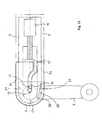
- Fig. 14 shows a cross section through the housing (1) in the region between the housing opening (13) and wedge surface (29).
- the wedge surface (29) is located here only in the upper area the front side wall (3), so that the side surface (23) below it on the front side wall (3) may be present.
- the upper part (20) is the Drehachsgliedes (10) designed such that the Wheelachsglied (10) and thus the Ball arm (9) in the position of use on the housing (1) can set.
- the lower cylindrical portion (18) of the Drehachsgliedes (10) analog to the upper part (20) to also contribute to the setting of the ball arm.
Landscapes
- Engineering & Computer Science (AREA)
- Transportation (AREA)
- Mechanical Engineering (AREA)
- Vehicle Cleaning, Maintenance, Repair, Refitting, And Outriggers (AREA)
- Component Parts Of Construction Machinery (AREA)
- Transmission Devices (AREA)
- Medicines Containing Plant Substances (AREA)
- Fuel Cell (AREA)
Abstract
Description
- Die Bodenfreiheit reicht (je nach Fahrzeugtyp) gelegentlich nicht aus, besonders wenn das Fahrzeug über einer Bordsteinkante steht
- Die senkrecht angeordnete Kugelstange hat eine Bauform, die bei moilemen Fahrzeugen mit besonders niedrig liegender Kofferraumkante nicht in das Fahrzeug integriert werden kann
- Aufwendige Konstruktion - teilweise mit 2 Motoren - um die drei Bewegungsschritte Senken, Schwenken, Heben zu realisieren
- Aufwendige Steuerung der Bewegungsschritte entweder mechanisch oder elektrisch
- Paßgenaue und damit teure Führungen erforderlich, die wegen der eingeleiteten Betriebskräfte teure Materialien und Bearbeitungsverfahren notwendig machen.
- Die Bodenfreiheit reicht bei bestimmten Ausführungsformen und Fahrzeugen ebenfalls nicht aus.
- Bei einigen Fahrzeugformen sind sie wegen der Art des Fahrzeugbodens nur schwer oder gar nicht zu integrieren.
- Die Getriebemotoren sind hohen Belastungen ausgesetzt, wodurch sie aufwendig und teuer werden. Es sind bei bestimmten Ausführungsformen zum Festsetzen der Kugelstange zusützliche Verriegelungsvorrichtungen erforderlich, die starkem Verschleiß unterliegen und teuer in der Herstellung sind.
- Die Hauptschwenklager unterliegen starken Betricbskräften und müssen daher in aufwendigen und teuren Techniken hergestellt werden.
- Zur Realisierung der Bewegung sind unter Umständen 2 Motoren erforderlich
- Es gibt wiederum drei Bewegungsschritte - Senken - Drehen - Heben - dazu ist eine spezielle Steuerung erforderlich
- Die Herstellung ist wegen zweier großer, die ganz Last aufnehmenden Lager aufwendig und teuer.
Durch den Schlitz (7) im Gehäuseboden (6) ragt der Kugelarm (9) hifidurch. Der sich im Gehäuse (1) befindliche Teil des Kugelarmes (9) ist als Drehachsglied (10) ausgeführt. Das Drehachsglied (10) besitzt im unteren Teil eine zylindrische Form, dessen Durchmesser größer als die lichte Weite des Schlitzes (7). Der obere Teil des Drehachsgliedes (10) ist asymmetrisch und wird in Fig. 5 näher beschrieben. Zwischen dem oberen und unteren Teil des Drehachsgliedes (10) ist eine Ringnut (19) angeordnet, in die eine Anlenkung (17) des Linearantriebes (16) eingreift. Der Linearantrieb (16) ist an der Gehäuserückwand (4) im Lager (23) schwenkbar gelagert.
Der Linearantrieb (16) ist ganz eingefahren, der Kugelarm (9) ist im Schlitz (7) in Richtung Gehäuserückwand (4) zurückgezogen. Der Kugelarm (9) steht parallel zur Längsachse (8).
In der Gebrauchsstellung ist der Kugelarm (9) mit Seitenflächen (23,24) und der Keilfläche (28) am halbzylindrischen Teil (21) des Drehachsghedes (10) zwischen der Keilfläche (29) an der vorderen Seitenwand (3) sowie der hinteren (2) und der vorderen Seitenwand (3) festgesetzt. Dadurch werden der Großteil der Kräfte, die von außen z.B. durch einen Anhänger auf den Kugelarm (9) einwirken, in das Gehäuse (1) eingeleitet. Nur ein kleiner Teil dieser Kräfte wirken auf den Linearantrieb (16).
Das Drehachsglied (10) besteht aus einem unteren zylindrischen Teil (18) und einem oberen Teil, der aus einem halbzylindrischen Teil (21), und einem halbquaderförmigen Teil mit den geraden Flächen (22,23,24) zusammengesetzt ist. Im oberen Teil (20) ist ein Teil der Seitenfläche (23) als Keilfläche (28) ausgearbeitet, welche in der Gebrauchsstellung mit einer Keilfläche (29) am Gehäuse (1) korrespondiert. Zwischen dem unteren und oberen Teil ist eine Ringnut (19) angeordnet, an der der Linearantrieb (16) mit der Anlenkung (17) angreift.
An der Anlenkung (17), die z.B. Teil einer Gewindehülse eines Spindelantriebes sein kann, befindet sich auf der dem Drehachsglied (10) zugewandten Seite eine teilkreisförmige Lagerfläche (25), deren Radius dem Radius der Ringnut (19) entspricht. Eine U-förmige Lagerfläche (26), die z.B. als U-förmiger Blechstreifen ausgeführt sein kann, umfasst den Kugelarm (9) in der Ringnut (19) und bildet bei Zusammenführung beider Teile in Pfeilrichtungen A,B mit der Lagerfläche (25) ein kreisförmiges Lager, in dem sich der Kugelarm (9) um die Schwenkachse (12) drehen kann. Die Verbindung zwischen den Lagerteilen (25,26) ist hier nicht näher dargestellt, sie kann z.B. durch eine Schrauh- oder Nietverbindung realisiert sein.
Solange der Linearantrieb (16) sich nicht wieder in die entgegengesetzte Richtung bewegt, bleibt der Kugelarm (9) fest in der Gebrauchsstellung, von außen einwirkende Kräfte werden in das Gehäuse und entlang der Längsachse (8) in den Linearantrieb (16) eingeleitet,
Claims (3)
- Anhängekupplung für Kraftfahrzeuge, insbesondere Personenkraftwagen mit einem Kupplungsarm (9), der einends ein hochstchend angeordnetes Kopfstück zum lösbaren Befestigen eines Anhängers trägt und anderenends mit einem bewegbar in einem Gehäuse (1) gelagerten Drehachsglied (10) fest verbunden ist, wobei der Kupplungsarm (9) mittels einer manuell oder kraftbetriebenen Vorschubeinrichtung (16) zwischen einer am Fahrzeug angeordneten nach hinten gerichteten Gebrauchsstellung und einer weiter vorne angeordneten Nichtgehrauchsstellung hin und her verstellbar ist und die Verstellbewegung sich aus zwei Bewegungen zusammensetzt, wobei beide Bewegungen sich auch überlagern können, in dem der Kupplungsarm, ausgehend von der Nichtgebrauchsstellung im ersten Bewegungsabschnitt durch Verschieben des Drehachsgliedes (10) im innerhalb des Fahrzeuges angeordneten Gehäuse (1) nach vorne in eine Zwischenstellung befördert wird und in einem zweiten Bewegungsabschrtitt das Drehachsglied (10) zusammen mit dem Kupplungsarm (9) verschwenkt wird, so daß der Kuppiungsarm (9) nach Vollendung beider Bewegungen die Gebrauchsstellung einnimmt, dadurch gekennzeichnet, daß an dem Kupplungsarm (9) an dem der Kugel gegenüberliegenden Ende ein Drehachsglied (10) angeordnet ist, das auf der einen Seite ein Teilzylinder (21) und dessen andere Seite ein quaderförmiger Körper ist, dessen kurze Seiten (23,24) in einem oberen Teil des Drehachsgliedes (10) in den Tangenten des Teilzylinders (21) auslaufen, und bei dem durch einen Sekantenschnitt eine Keilfläche (28) gebildet wird, wodurch sich in der Draufsicht auf das Drehachsglied (10) im oberen Teil ein schildförmiges Profil ergibt, wobei die Mittelachse (12) des Zylinders in die Mittelachse des Kupplungsarmes übergeht und der Abstand der langen Seite (22) des Halbquaders (Oberkante des Schildes) von der Mittelachse des Teilzylinders dem Radius des Teilzylinders entspricht und dieses Drehachsglied (10) in einem u-schienenförmigen, das Drehachsglied (10) umhüllenden Gehäuse (1), eine entsprechende Ausnchmung (13) vorfindet, in die, durch den manuellen oder kraftangetriebenen Stellantrieb (16) bei schwenkender Bewegung des Kupplungsarmes (9) und des Drehachsgliedes (10) der obere Teil des schildförmigen Drehachsgliedes (10) eintauchen kann, wenn gleichzeitig ein am Oberteil des Drehachsgliedes (10) exzentrisch zur Mittelachse angeordneter Mitnehmerbolzen (11) gegen einen am Gehäuse (1) sitzenden Anschlag (14,15) läuft und dabei durch die Kraft des Stellantriebes (16) das Drehachsglied (10) in Drehung um die Mittelachse des Teilzylinders (12) versetzt wird, so lange, bis das Drehachsglied (10) mit dem Kupplungsarm (9) ca. 90° geschwenkt hat und der schikiförmige Teil des Drchachsgliedes (10) mit der Keiltläche (28) in das zur Keilfläche (28) passende Formteil (29) am Gehäuse (1) eingreift, während gleichzeitig der Mitnehmerbolzen (11) in die Kurvenbahn (15) am Gehäuse (1) eintaucht und am Ende der Kurvenbahn das schildförmige Drchachsglied durch den Preßdruck des Stellantriebes (16) verdrehsicher gehalten wird, weil die schildförmigen Kanten (23,24) des Drchachsgliedes (10) zwischen den Gehäusewandungen (2,3,5) verkeilt sind.
- Anhängekupplung für Kraftfahrzeuge nach Anspruch 1 dadurch gekennzeichnet, daß in dem Gehäuse (1) statt eines durchgehenden Gehäuscbodens (6) auch zwei oder mehrere Gehäuseböden hintereinander in unterschiedlichen Winkeln zur Horizontale angeordnet sein können.
- Anhängekupplung für Kraftfahrzeuge nach Anspruch 1 dadurch gekennzeichnet, daß das Drehachsglied (10) in Zahnradform ausgebildet ist und am Ende seiner Linearbewegung auf eine am Gehäuse angeordnete Zahnstange trifft, in die das zahnradförmige Drehachsglied dann eingreift und die durch die Kraft des Lincarantriebes (16) zur Drehbewegung des Kupplungsarms (9) führt.
Applications Claiming Priority (2)
| Application Number | Priority Date | Filing Date | Title |
|---|---|---|---|
| DE202004006205U DE202004006205U1 (de) | 2004-04-17 | 2004-04-17 | Anhängerkupplung |
| DE202004006205U | 2004-04-17 |
Publications (2)
| Publication Number | Publication Date |
|---|---|
| EP1586470A1 true EP1586470A1 (de) | 2005-10-19 |
| EP1586470B1 EP1586470B1 (de) | 2008-12-24 |
Family
ID=32668345
Family Applications (1)
| Application Number | Title | Priority Date | Filing Date |
|---|---|---|---|
| EP05005545A Expired - Lifetime EP1586470B1 (de) | 2004-04-17 | 2005-03-15 | Anhängerkupplung |
Country Status (3)
| Country | Link |
|---|---|
| EP (1) | EP1586470B1 (de) |
| AT (1) | ATE418465T1 (de) |
| DE (2) | DE202004006205U1 (de) |
Cited By (4)
| Publication number | Priority date | Publication date | Assignee | Title |
|---|---|---|---|---|
| WO2008049569A1 (de) | 2006-10-25 | 2008-05-02 | Rheinisch-Westfälische Technische Hochschule Aachen | Anhängevorrichtung |
| EP2181868A1 (de) | 2008-10-30 | 2010-05-05 | MVG Metallverarbeitungsgesellschaft mbH | Anhängekupplung |
| US11059336B1 (en) * | 2018-04-05 | 2021-07-13 | Charles L. Perry | Retractable hitch adaptor system |
| US11577559B2 (en) | 2020-06-03 | 2023-02-14 | Ford Global Technologies, Llc | Vehicle tow hook |
Citations (8)
| Publication number | Priority date | Publication date | Assignee | Title |
|---|---|---|---|---|
| US4109930A (en) * | 1975-05-06 | 1978-08-29 | Ab Volvo | Towing device for motor vehicles |
| DE10023640A1 (de) * | 2000-05-13 | 2001-11-15 | Fac Frank Abels Consult & Tech | Anhängerkupplung |
| DE10023641A1 (de) * | 2000-05-13 | 2001-11-15 | Fac Frank Abels Consult & Tech | Anhängerkupplung |
| DE10104185A1 (de) * | 2001-01-23 | 2002-07-25 | Fac Frank Abels Consult & Tech | Anhängerkupplung |
| US6447000B1 (en) * | 1999-02-05 | 2002-09-10 | Popup Industries, Inc. | Mechanism for retractable gooseneck hitch ball |
| EP1380445A1 (de) * | 2002-07-11 | 2004-01-14 | Dr.Ing. h.c.F. Porsche Aktiengesellschaft | Anhängezugvorrichtung |
| DE10243045A1 (de) * | 2002-09-12 | 2004-03-25 | Fac Frank Abels Consulting & Technology Gesellschaft Mbh | Anhängerkupplung |
| DE202004006666U1 (de) * | 2003-12-13 | 2004-08-19 | Fac Frank Abels Consulting & Technology Gesellschaft Mbh | Anhängerkupplung |
-
2004
- 2004-04-17 DE DE202004006205U patent/DE202004006205U1/de not_active Expired - Lifetime
-
2005
- 2005-03-15 EP EP05005545A patent/EP1586470B1/de not_active Expired - Lifetime
- 2005-03-15 DE DE502005006306T patent/DE502005006306D1/de not_active Expired - Lifetime
- 2005-03-15 AT AT05005545T patent/ATE418465T1/de not_active IP Right Cessation
Patent Citations (8)
| Publication number | Priority date | Publication date | Assignee | Title |
|---|---|---|---|---|
| US4109930A (en) * | 1975-05-06 | 1978-08-29 | Ab Volvo | Towing device for motor vehicles |
| US6447000B1 (en) * | 1999-02-05 | 2002-09-10 | Popup Industries, Inc. | Mechanism for retractable gooseneck hitch ball |
| DE10023640A1 (de) * | 2000-05-13 | 2001-11-15 | Fac Frank Abels Consult & Tech | Anhängerkupplung |
| DE10023641A1 (de) * | 2000-05-13 | 2001-11-15 | Fac Frank Abels Consult & Tech | Anhängerkupplung |
| DE10104185A1 (de) * | 2001-01-23 | 2002-07-25 | Fac Frank Abels Consult & Tech | Anhängerkupplung |
| EP1380445A1 (de) * | 2002-07-11 | 2004-01-14 | Dr.Ing. h.c.F. Porsche Aktiengesellschaft | Anhängezugvorrichtung |
| DE10243045A1 (de) * | 2002-09-12 | 2004-03-25 | Fac Frank Abels Consulting & Technology Gesellschaft Mbh | Anhängerkupplung |
| DE202004006666U1 (de) * | 2003-12-13 | 2004-08-19 | Fac Frank Abels Consulting & Technology Gesellschaft Mbh | Anhängerkupplung |
Cited By (6)
| Publication number | Priority date | Publication date | Assignee | Title |
|---|---|---|---|---|
| WO2008049569A1 (de) | 2006-10-25 | 2008-05-02 | Rheinisch-Westfälische Technische Hochschule Aachen | Anhängevorrichtung |
| DE102006051096B4 (de) * | 2006-10-25 | 2013-09-12 | Mvg Metallverarbeitungsgesellschaft Mbh | Anhängevorrichtung |
| EP2181868A1 (de) | 2008-10-30 | 2010-05-05 | MVG Metallverarbeitungsgesellschaft mbH | Anhängekupplung |
| DE102008043318A1 (de) | 2008-10-30 | 2010-05-12 | Mvg Metallverarbeitungsgesellschaft Mbh | Anhängekupplung |
| US11059336B1 (en) * | 2018-04-05 | 2021-07-13 | Charles L. Perry | Retractable hitch adaptor system |
| US11577559B2 (en) | 2020-06-03 | 2023-02-14 | Ford Global Technologies, Llc | Vehicle tow hook |
Also Published As
| Publication number | Publication date |
|---|---|
| DE202004006205U1 (de) | 2004-07-01 |
| DE502005006306D1 (de) | 2009-02-05 |
| EP1586470B1 (de) | 2008-12-24 |
| ATE418465T1 (de) | 2009-01-15 |
Similar Documents
| Publication | Publication Date | Title |
|---|---|---|
| DE19840007B4 (de) | Schleppzug | |
| EP1435305B1 (de) | Anhängekupplung | |
| EP1902871B1 (de) | Anhängekupplung | |
| DE102005007430A1 (de) | Befestigungs- und Positioniervorrichtung für einen Fahrzeugsitz | |
| DE19654867A1 (de) | Schwenkbare Anhängerkupplung für Kraftfahrzeuge | |
| DE102011001924B4 (de) | Transfereinrichtung für eine Presse oder Pressenstraße mit Achsantrieb und auswechselbarem Grundträger | |
| EP1880879A1 (de) | Schwenkbare Anhängevorrichtung für Zugfahrzeuge | |
| DE4031568C1 (en) | Rear seat for motor vehicle - has back rest position adjusted via swivel bearing on crank linkage | |
| AT512215B1 (de) | Scheinwerfer, insbesondere motorradscheinwerfer | |
| EP1535765A1 (de) | Anhängerkupplung | |
| EP1541385B1 (de) | Anhängerkupplung für Kraftfahrzeuge | |
| EP1584499B1 (de) | Anhängerkupplung | |
| EP1905617A1 (de) | Anhängerkupplung | |
| EP1090782A2 (de) | Anhängerkupplung für Kraftfahrzeuge | |
| EP1584500A1 (de) | Anhängerkupplung | |
| DE102010043207B4 (de) | Anhänger | |
| EP1544003B1 (de) | Anhängekupplung für Personenkraftfahrzeuge | |
| EP1586471A1 (de) | Anhängerkupplung | |
| EP1586470A1 (de) | Anhängerkupplung | |
| DE2138674A1 (de) | Ladevorrichtung fuer lastfahrzeuge | |
| DE10131397A1 (de) | Windschott für ein Kraftfahrzeug | |
| EP1056556A1 (de) | Bördeleinrichtung mit press- und spannelementen | |
| DE202004006666U1 (de) | Anhängerkupplung | |
| EP1584498A1 (de) | Anhängerkupplung | |
| DE10347816B4 (de) | Anhängekupplung mit lastfreier Drehlagereinrichtung |
Legal Events
| Date | Code | Title | Description |
|---|---|---|---|
| PUAI | Public reference made under article 153(3) epc to a published international application that has entered the european phase |
Free format text: ORIGINAL CODE: 0009012 |
|
| AK | Designated contracting states |
Kind code of ref document: A1 Designated state(s): AT BE BG CH CY CZ DE DK EE ES FI FR GB GR HU IE IS IT LI LT LU MC NL PL PT RO SE SI SK TR |
|
| AX | Request for extension of the european patent |
Extension state: AL BA HR LV MK YU |
|
| 17P | Request for examination filed |
Effective date: 20060317 |
|
| AKX | Designation fees paid |
Designated state(s): AT BE BG CH CY CZ DE DK EE ES FI FR GB GR HU IE IS IT LI LT LU MC NL PL PT RO SE SI SK TR |
|
| RAP1 | Party data changed (applicant data changed or rights of an application transferred) |
Owner name: WESTFALIA - AUTOMOTIVE GMBH |
|
| 17Q | First examination report despatched |
Effective date: 20070131 |
|
| GRAP | Despatch of communication of intention to grant a patent |
Free format text: ORIGINAL CODE: EPIDOSNIGR1 |
|
| GRAS | Grant fee paid |
Free format text: ORIGINAL CODE: EPIDOSNIGR3 |
|
| GRAA | (expected) grant |
Free format text: ORIGINAL CODE: 0009210 |
|
| AK | Designated contracting states |
Kind code of ref document: B1 Designated state(s): AT BE BG CH CY CZ DE DK EE ES FI FR GB GR HU IE IS IT LI LT LU MC NL PL PT RO SE SI SK TR |
|
| REG | Reference to a national code |
Ref country code: GB Ref legal event code: FG4D Free format text: NOT ENGLISH |
|
| REG | Reference to a national code |
Ref country code: CH Ref legal event code: EP |
|
| REG | Reference to a national code |
Ref country code: IE Ref legal event code: FG4D Free format text: LANGUAGE OF EP DOCUMENT: GERMAN |
|
| REF | Corresponds to: |
Ref document number: 502005006306 Country of ref document: DE Date of ref document: 20090205 Kind code of ref document: P |
|
| PG25 | Lapsed in a contracting state [announced via postgrant information from national office to epo] |
Ref country code: LT Free format text: LAPSE BECAUSE OF FAILURE TO SUBMIT A TRANSLATION OF THE DESCRIPTION OR TO PAY THE FEE WITHIN THE PRESCRIBED TIME-LIMIT Effective date: 20081224 |
|
| PG25 | Lapsed in a contracting state [announced via postgrant information from national office to epo] |
Ref country code: NL Free format text: LAPSE BECAUSE OF FAILURE TO SUBMIT A TRANSLATION OF THE DESCRIPTION OR TO PAY THE FEE WITHIN THE PRESCRIBED TIME-LIMIT Effective date: 20081224 Ref country code: PL Free format text: LAPSE BECAUSE OF FAILURE TO SUBMIT A TRANSLATION OF THE DESCRIPTION OR TO PAY THE FEE WITHIN THE PRESCRIBED TIME-LIMIT Effective date: 20081224 Ref country code: SI Free format text: LAPSE BECAUSE OF FAILURE TO SUBMIT A TRANSLATION OF THE DESCRIPTION OR TO PAY THE FEE WITHIN THE PRESCRIBED TIME-LIMIT Effective date: 20081224 Ref country code: FI Free format text: LAPSE BECAUSE OF FAILURE TO SUBMIT A TRANSLATION OF THE DESCRIPTION OR TO PAY THE FEE WITHIN THE PRESCRIBED TIME-LIMIT Effective date: 20081224 |
|
| NLV1 | Nl: lapsed or annulled due to failure to fulfill the requirements of art. 29p and 29m of the patents act | ||
| REG | Reference to a national code |
Ref country code: IE Ref legal event code: FD4D |
|
| PG25 | Lapsed in a contracting state [announced via postgrant information from national office to epo] |
Ref country code: RO Free format text: LAPSE BECAUSE OF FAILURE TO SUBMIT A TRANSLATION OF THE DESCRIPTION OR TO PAY THE FEE WITHIN THE PRESCRIBED TIME-LIMIT Effective date: 20081224 Ref country code: IE Free format text: LAPSE BECAUSE OF FAILURE TO SUBMIT A TRANSLATION OF THE DESCRIPTION OR TO PAY THE FEE WITHIN THE PRESCRIBED TIME-LIMIT Effective date: 20081224 Ref country code: BG Free format text: LAPSE BECAUSE OF FAILURE TO SUBMIT A TRANSLATION OF THE DESCRIPTION OR TO PAY THE FEE WITHIN THE PRESCRIBED TIME-LIMIT Effective date: 20090324 Ref country code: ES Free format text: LAPSE BECAUSE OF FAILURE TO SUBMIT A TRANSLATION OF THE DESCRIPTION OR TO PAY THE FEE WITHIN THE PRESCRIBED TIME-LIMIT Effective date: 20090404 Ref country code: EE Free format text: LAPSE BECAUSE OF FAILURE TO SUBMIT A TRANSLATION OF THE DESCRIPTION OR TO PAY THE FEE WITHIN THE PRESCRIBED TIME-LIMIT Effective date: 20081224 |
|
| PG25 | Lapsed in a contracting state [announced via postgrant information from national office to epo] |
Ref country code: CZ Free format text: LAPSE BECAUSE OF FAILURE TO SUBMIT A TRANSLATION OF THE DESCRIPTION OR TO PAY THE FEE WITHIN THE PRESCRIBED TIME-LIMIT Effective date: 20081224 Ref country code: PT Free format text: LAPSE BECAUSE OF FAILURE TO SUBMIT A TRANSLATION OF THE DESCRIPTION OR TO PAY THE FEE WITHIN THE PRESCRIBED TIME-LIMIT Effective date: 20090525 Ref country code: IS Free format text: LAPSE BECAUSE OF FAILURE TO SUBMIT A TRANSLATION OF THE DESCRIPTION OR TO PAY THE FEE WITHIN THE PRESCRIBED TIME-LIMIT Effective date: 20090424 Ref country code: SE Free format text: LAPSE BECAUSE OF FAILURE TO SUBMIT A TRANSLATION OF THE DESCRIPTION OR TO PAY THE FEE WITHIN THE PRESCRIBED TIME-LIMIT Effective date: 20090324 |
|
| BERE | Be: lapsed |
Owner name: WESTFALIA - AUTOMOTIVE G.M.B.H. Effective date: 20090331 |
|
| PG25 | Lapsed in a contracting state [announced via postgrant information from national office to epo] |
Ref country code: SK Free format text: LAPSE BECAUSE OF FAILURE TO SUBMIT A TRANSLATION OF THE DESCRIPTION OR TO PAY THE FEE WITHIN THE PRESCRIBED TIME-LIMIT Effective date: 20081224 |
|
| PG25 | Lapsed in a contracting state [announced via postgrant information from national office to epo] |
Ref country code: MC Free format text: LAPSE BECAUSE OF NON-PAYMENT OF DUE FEES Effective date: 20090331 Ref country code: DK Free format text: LAPSE BECAUSE OF FAILURE TO SUBMIT A TRANSLATION OF THE DESCRIPTION OR TO PAY THE FEE WITHIN THE PRESCRIBED TIME-LIMIT Effective date: 20081224 |
|
| PLBE | No opposition filed within time limit |
Free format text: ORIGINAL CODE: 0009261 |
|
| REG | Reference to a national code |
Ref country code: CH Ref legal event code: PL |
|
| STAA | Information on the status of an ep patent application or granted ep patent |
Free format text: STATUS: NO OPPOSITION FILED WITHIN TIME LIMIT |
|
| GBPC | Gb: european patent ceased through non-payment of renewal fee |
Effective date: 20090324 |
|
| 26N | No opposition filed |
Effective date: 20090925 |
|
| REG | Reference to a national code |
Ref country code: FR Ref legal event code: ST Effective date: 20091130 |
|
| PG25 | Lapsed in a contracting state [announced via postgrant information from national office to epo] |
Ref country code: CH Free format text: LAPSE BECAUSE OF NON-PAYMENT OF DUE FEES Effective date: 20090331 Ref country code: LI Free format text: LAPSE BECAUSE OF NON-PAYMENT OF DUE FEES Effective date: 20090331 |
|
| PG25 | Lapsed in a contracting state [announced via postgrant information from national office to epo] |
Ref country code: BE Free format text: LAPSE BECAUSE OF NON-PAYMENT OF DUE FEES Effective date: 20090331 |
|
| PG25 | Lapsed in a contracting state [announced via postgrant information from national office to epo] |
Ref country code: GB Free format text: LAPSE BECAUSE OF NON-PAYMENT OF DUE FEES Effective date: 20090324 Ref country code: FR Free format text: LAPSE BECAUSE OF NON-PAYMENT OF DUE FEES Effective date: 20091123 |
|
| PG25 | Lapsed in a contracting state [announced via postgrant information from national office to epo] |
Ref country code: AT Free format text: LAPSE BECAUSE OF NON-PAYMENT OF DUE FEES Effective date: 20090315 |
|
| PG25 | Lapsed in a contracting state [announced via postgrant information from national office to epo] |
Ref country code: GR Free format text: LAPSE BECAUSE OF FAILURE TO SUBMIT A TRANSLATION OF THE DESCRIPTION OR TO PAY THE FEE WITHIN THE PRESCRIBED TIME-LIMIT Effective date: 20090325 |
|
| PG25 | Lapsed in a contracting state [announced via postgrant information from national office to epo] |
Ref country code: IT Free format text: LAPSE BECAUSE OF FAILURE TO SUBMIT A TRANSLATION OF THE DESCRIPTION OR TO PAY THE FEE WITHIN THE PRESCRIBED TIME-LIMIT Effective date: 20081224 |
|
| PG25 | Lapsed in a contracting state [announced via postgrant information from national office to epo] |
Ref country code: LU Free format text: LAPSE BECAUSE OF NON-PAYMENT OF DUE FEES Effective date: 20090315 |
|
| PG25 | Lapsed in a contracting state [announced via postgrant information from national office to epo] |
Ref country code: HU Free format text: LAPSE BECAUSE OF FAILURE TO SUBMIT A TRANSLATION OF THE DESCRIPTION OR TO PAY THE FEE WITHIN THE PRESCRIBED TIME-LIMIT Effective date: 20090625 |
|
| PG25 | Lapsed in a contracting state [announced via postgrant information from national office to epo] |
Ref country code: TR Free format text: LAPSE BECAUSE OF FAILURE TO SUBMIT A TRANSLATION OF THE DESCRIPTION OR TO PAY THE FEE WITHIN THE PRESCRIBED TIME-LIMIT Effective date: 20081224 |
|
| PG25 | Lapsed in a contracting state [announced via postgrant information from national office to epo] |
Ref country code: CY Free format text: LAPSE BECAUSE OF FAILURE TO SUBMIT A TRANSLATION OF THE DESCRIPTION OR TO PAY THE FEE WITHIN THE PRESCRIBED TIME-LIMIT Effective date: 20081224 |
|
| REG | Reference to a national code |
Ref country code: DE Ref legal event code: R082 Ref document number: 502005006306 Country of ref document: DE Representative=s name: BREGENZER, MICHAEL, DIPL.-ING., DE Ref country code: DE Ref legal event code: R082 Ref document number: 502005006306 Country of ref document: DE Representative=s name: PATENTANWAELTE BREGENZER UND REULE PARTNERSCHA, DE |
|
| REG | Reference to a national code |
Ref country code: DE Ref legal event code: R082 Ref document number: 502005006306 Country of ref document: DE Representative=s name: PATENTANWAELTE BREGENZER UND REULE PARTNERSCHA, DE |
|
| PGFP | Annual fee paid to national office [announced via postgrant information from national office to epo] |
Ref country code: DE Payment date: 20220309 Year of fee payment: 18 |
|
| REG | Reference to a national code |
Ref country code: DE Ref legal event code: R119 Ref document number: 502005006306 Country of ref document: DE |
|
| PG25 | Lapsed in a contracting state [announced via postgrant information from national office to epo] |
Ref country code: DE Free format text: LAPSE BECAUSE OF NON-PAYMENT OF DUE FEES Effective date: 20231003 |