EP1586203B1 - Nichtkollinearelicht-engine für farbabbildungssysteme - Google Patents
Nichtkollinearelicht-engine für farbabbildungssysteme Download PDFInfo
- Publication number
- EP1586203B1 EP1586203B1 EP04700083A EP04700083A EP1586203B1 EP 1586203 B1 EP1586203 B1 EP 1586203B1 EP 04700083 A EP04700083 A EP 04700083A EP 04700083 A EP04700083 A EP 04700083A EP 1586203 B1 EP1586203 B1 EP 1586203B1
- Authority
- EP
- European Patent Office
- Prior art keywords
- light
- beam splitter
- polarization beam
- color
- coupled
- Prior art date
- Legal status (The legal status is an assumption and is not a legal conclusion. Google has not performed a legal analysis and makes no representation as to the accuracy of the status listed.)
- Expired - Lifetime
Links
- 238000003384 imaging method Methods 0.000 title claims abstract description 61
- 230000010287 polarization Effects 0.000 claims abstract description 52
- 230000003287 optical effect Effects 0.000 claims abstract description 21
- 238000000034 method Methods 0.000 claims description 4
- 230000008878 coupling Effects 0.000 claims 3
- 238000010168 coupling process Methods 0.000 claims 3
- 238000005859 coupling reaction Methods 0.000 claims 3
- 238000004519 manufacturing process Methods 0.000 claims 1
- 239000003086 colorant Substances 0.000 abstract description 6
- 238000012545 processing Methods 0.000 abstract description 3
- 238000005457 optimization Methods 0.000 description 3
- 238000013461 design Methods 0.000 description 2
- 238000005286 illumination Methods 0.000 description 2
- 238000012986 modification Methods 0.000 description 2
- 230000004048 modification Effects 0.000 description 2
- 238000011045 prefiltration Methods 0.000 description 2
- XUIMIQQOPSSXEZ-UHFFFAOYSA-N Silicon Chemical compound [Si] XUIMIQQOPSSXEZ-UHFFFAOYSA-N 0.000 description 1
- 230000004913 activation Effects 0.000 description 1
- 230000015556 catabolic process Effects 0.000 description 1
- 238000012937 correction Methods 0.000 description 1
- 238000006731 degradation reaction Methods 0.000 description 1
- 238000001914 filtration Methods 0.000 description 1
- 239000004973 liquid crystal related substance Substances 0.000 description 1
- 230000001902 propagating effect Effects 0.000 description 1
- 229910052710 silicon Inorganic materials 0.000 description 1
- 239000010703 silicon Substances 0.000 description 1
Images



Classifications
-
- H—ELECTRICITY
- H04—ELECTRIC COMMUNICATION TECHNIQUE
- H04N—PICTORIAL COMMUNICATION, e.g. TELEVISION
- H04N9/00—Details of colour television systems
- H04N9/12—Picture reproducers
- H04N9/31—Projection devices for colour picture display, e.g. using electronic spatial light modulators [ESLM]
- H04N9/3102—Projection devices for colour picture display, e.g. using electronic spatial light modulators [ESLM] using two-dimensional electronic spatial light modulators
- H04N9/3105—Projection devices for colour picture display, e.g. using electronic spatial light modulators [ESLM] using two-dimensional electronic spatial light modulators for displaying all colours simultaneously, e.g. by using two or more electronic spatial light modulators
-
- G—PHYSICS
- G03—PHOTOGRAPHY; CINEMATOGRAPHY; ANALOGOUS TECHNIQUES USING WAVES OTHER THAN OPTICAL WAVES; ELECTROGRAPHY; HOLOGRAPHY
- G03B—APPARATUS OR ARRANGEMENTS FOR TAKING PHOTOGRAPHS OR FOR PROJECTING OR VIEWING THEM; APPARATUS OR ARRANGEMENTS EMPLOYING ANALOGOUS TECHNIQUES USING WAVES OTHER THAN OPTICAL WAVES; ACCESSORIES THEREFOR
- G03B21/00—Projectors or projection-type viewers; Accessories therefor
- G03B21/005—Projectors using an electronic spatial light modulator but not peculiar thereto
-
- G—PHYSICS
- G03—PHOTOGRAPHY; CINEMATOGRAPHY; ANALOGOUS TECHNIQUES USING WAVES OTHER THAN OPTICAL WAVES; ELECTROGRAPHY; HOLOGRAPHY
- G03B—APPARATUS OR ARRANGEMENTS FOR TAKING PHOTOGRAPHS OR FOR PROJECTING OR VIEWING THEM; APPARATUS OR ARRANGEMENTS EMPLOYING ANALOGOUS TECHNIQUES USING WAVES OTHER THAN OPTICAL WAVES; ACCESSORIES THEREFOR
- G03B33/00—Colour photography, other than mere exposure or projection of a colour film
- G03B33/08—Sequential recording or projection
-
- G—PHYSICS
- G03—PHOTOGRAPHY; CINEMATOGRAPHY; ANALOGOUS TECHNIQUES USING WAVES OTHER THAN OPTICAL WAVES; ELECTROGRAPHY; HOLOGRAPHY
- G03B—APPARATUS OR ARRANGEMENTS FOR TAKING PHOTOGRAPHS OR FOR PROJECTING OR VIEWING THEM; APPARATUS OR ARRANGEMENTS EMPLOYING ANALOGOUS TECHNIQUES USING WAVES OTHER THAN OPTICAL WAVES; ACCESSORIES THEREFOR
- G03B33/00—Colour photography, other than mere exposure or projection of a colour film
- G03B33/10—Simultaneous recording or projection
- G03B33/14—Simultaneous recording or projection using lenticular screens
-
- H—ELECTRICITY
- H04—ELECTRIC COMMUNICATION TECHNIQUE
- H04N—PICTORIAL COMMUNICATION, e.g. TELEVISION
- H04N9/00—Details of colour television systems
- H04N9/12—Picture reproducers
- H04N9/31—Projection devices for colour picture display, e.g. using electronic spatial light modulators [ESLM]
- H04N9/3102—Projection devices for colour picture display, e.g. using electronic spatial light modulators [ESLM] using two-dimensional electronic spatial light modulators
-
- H—ELECTRICITY
- H04—ELECTRIC COMMUNICATION TECHNIQUE
- H04N—PICTORIAL COMMUNICATION, e.g. TELEVISION
- H04N9/00—Details of colour television systems
- H04N9/12—Picture reproducers
- H04N9/31—Projection devices for colour picture display, e.g. using electronic spatial light modulators [ESLM]
- H04N9/3102—Projection devices for colour picture display, e.g. using electronic spatial light modulators [ESLM] using two-dimensional electronic spatial light modulators
- H04N9/3111—Projection devices for colour picture display, e.g. using electronic spatial light modulators [ESLM] using two-dimensional electronic spatial light modulators for displaying the colours sequentially, e.g. by using sequentially activated light sources
-
- H—ELECTRICITY
- H04—ELECTRIC COMMUNICATION TECHNIQUE
- H04N—PICTORIAL COMMUNICATION, e.g. TELEVISION
- H04N9/00—Details of colour television systems
- H04N9/12—Picture reproducers
- H04N9/31—Projection devices for colour picture display, e.g. using electronic spatial light modulators [ESLM]
- H04N9/3141—Constructional details thereof
- H04N9/315—Modulator illumination systems
- H04N9/3167—Modulator illumination systems for polarizing the light beam
Definitions
- This invention relates generally to light engines for projection display systems, and more specifically to light engines for use with color imaging systems.
- a light source is used for a light engine, enabling projection of images in a display system.
- many types of light engines may provide light to project color images for a variety of projection display systems, including a color imaging system.
- An example of such a light engine is a collinear light engine that is shown in Figure 1 in connection with a color imaging system 5 according to a prior art projection display system.
- the prior art system 5 utilizes a light source 10, such as an ultra high-pressure (UHP) lamp 10 to provide light.
- UHP ultra high-pressure
- the set of optical components may include an ultraviolet and infrared (UV-IR) filter 12, a light pipe homogenizer 14, a color switch or color wheel 16, and a lens 18 by way of one example.
- UV-IR ultraviolet and infrared
- a conventional polarizer such as an output polarization analyzer 20 may serve to pass the light of a first polarization "P" while skipping or reflecting the light of a second polarization "S.”
- the color switch 16 in combination with the output polarization analyzer 20 may ideally pass red light through, for example, and selectably switch or alternate between either passing blue light and reflecting green light or passing green light and reflecting blue light.
- the prior art system 5 may further include an imaging pre-filter, i.e., an RC1 filter 22 which is deployed in the output region of the lens 18.
- a polarization beam splitter (PBS) 24 with a first side facing the RC1 filter 22 may additionally be provided thereafter.
- PBS 24 polarization beam splitter
- a quarter-wave ( ⁇ /4, ⁇ being the wavelength) retarder 26 and a first spatial light modulator (SLM) 28 may be located on a second side of the PBS 24.
- an electronic drive may present to the first SLM 28 image data that alternates between blue and green image data, while the second SLM 32 may be presented only with red image data.
- a clean-up polarizer 38, and a projection lens 40 may be configured on a fourth side of the PBS 24 to provide an output beam based on a particular electronic drive, presenting image data in a specific format including a red-bluegreen (RGB) format, as one example.
- RGB red-bluegreen
- the prior art system 5 may typically be said to include a light engine incorporating the elements 10, 12 and 14, a color switch subsystem including the elements 16, 18 and 20, an imaging subsystem or kernel comprising the elements 22 through 38, and a projection subsystem that includes element 40.
- the color switch subsystem may be said to have an input axis (Axis IKin ) through the first side of the PBS 24, and the light source 10 which may be said to have an output axis (Axis LEout ) through the light pipe homogenizer 14. Because the input axis of the color switch subsystem is in a coaxial or a collinear orientation with respect to the output axis of the light source 10, the prior art system 5 is usually characterized as a collinear panel-based projection display system.
- contrast ratio is often a significant design feature.
- leakage of light with an incorrect polarization through the color switch 16 and the output polarization analyzer 20 typically contributes to the background leakage illumination, reducing the contrast ratio.
- the color switch 16 imperfectly switches between blue and green, some amount of the reflected color light may pass through to the first SLM 28 while it is still modulating the earlier passed color light.
- the color switch 16 while passing green light (on the left) may undesirably reflect blue light (on the right), causing the blue leakage light (B L ) to appear in the output beam from the projection lens 40.
- imperfections in the operation of the output polarization analyzer 20 may further contaminate the output beam.
- the input filter UV-IR filter 12
- the input filter may also improperly reflect the "S" polarization green light (on the left, shown as a dashed line).
- this green light leakage may strike the first SLM 28 along with the "P" polarization green light, reflecting both the green light and leakage thereof into the output beam (shown as G L and G, respectively). Therefore, leakage of light with the incorrect polarization, onto the spatial light modulators and into the output beam may cause undesirable degradation of a projected image in a panel-based color imaging system.
- a false contour correction apparatus and method comprising an optical engine wherein light from an optical source is directed to a first polarized beam splitter through a collimating lens and color switching means, from where it is directed along two separate optical paths to two separate LCD panels through a mirror, from where it impinges on a second polarized beam splitter, which outputs the light through a projection lens.
- an image projection apparatus is provided based on an improvement of a wavelength shift of an incident light caused by the angle dependence of a dichroic prism.
- EP 1 199 896 A2 discloses a projection type video display apparatus having a polarization converter for matching light, which is output by the light source unit, to one of s-polarized light and p-polarized light, an optical characteristic switching element for switching a wavelength band of light output by the polarization converter and a video display element, as a light wave element, for forming an optical image from the light output by the light source unit in accordance with a video signal.
- a two-channel field sequential display system utilises a simultaneous and sequential color display method to display full color images.
- the two-channel field sequential display system displays two of three primary colors that make up the image simultaneously during a portion of a display frame and displays the third primary color sequentially during the subsequent part of the display frame.
- the invention provides an apparatus of claim 1 and method of claim 12, respectively.
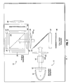
- a panel-based color imaging system 15 shown in Figure 2 may include an imaging subsystem or kernel 13 in which the input axis is in a non-collinear relationship with the output axis of a light engine 11 associated with an illumination subsystem, according to one embodiment of the present invention.
- similar components of the panel-based color imaging system 15 use the same reference numerals as their counterparts in the prior art system 5 shown in Figure 1 . This does not, however, mean that these components are required to be identical because various components in different embodiments of the present invention, may be altered, substituted, omitted, or added based on a specific projection display system architecture falling within the scope of the appended claims.
- the output polarization analyzer 20 of the prior art system 5 which is oriented perpendicularly to the light source's 10 output axis and the color switch subsystem's input axis, may be replaced in one embodiment of the present invention with an input polarization beam splitter (PBS) 42 which may comprise a MacNeille PBS or a wire grid plate PBS, as a few examples.
- PBS input polarization beam splitter
- the input and output axes i.e. (Axis IKin ), and (Axis LEout ) may be oriented at 90° relative to each other.
- different non-collinear orientations may be selected based on a particular application at hand, such as one involving an optimal angular incident on a first polarizer, i.e., the input PBS 42.
- the input PBS 42 may be disposed at 45° angles to both the axes. Other angles between the input and output axes may certainly be used, so long as there are adequate dump ports for dumping undesired light out of one or more optical paths of the panel-based color imaging system 15.
- RGB red-green-blue
- essentially the reduction of the leakage of the green and/or blue light, i.e., green and blue "P" polarizations from a critical optical path before this leakage reaches the imaging subsystem or kernel 13, may provide desired color yield with a relatively lower color loss.
- color corner coordinates may be improved while increasing brightness.
- a critical optical path may refer to an optical path from the light source 10 to the projection lens 40 in many examples of the present invention.
- contrast ratio may be significantly improved in projection display systems which may incorporate two or more panels.
- the panel-based color imaging system 15 further includes a color switch 44 that, in some situations, may ideally pass red light, and switch between passing either green and/or blue light.
- the color switch 44 may include a red twist filter.
- the red twist filter may be a separate element from the color switch 44.
- a turn-around polarizer 46 may be provided in the reflection output path of the input PBS 42.
- the turn-around polarizer 46 may comprise a MacNeille PBS or a wire grid plate PBS, as two examples.
- the color switch 44 may switch phase of all three colors in many cases.
- the panel-based color imaging system 15 shown in Figure 2 may involve red/blue phase switching, outputting the red and blue colors.
- the light engine 11 may emit red light (R), green light (G), and blue light (B), providing three color beams that strike the input PBS 42.
- the three color beams may include a first polarization "P" that passes through the input PBS 42, exiting from a first dump port 48a. In other words, the first polarization "P" may be discarded. However, light from the second polarization "S” may be reflected to the color switch 16.
- a polarization filter i.e., a RC3 filter 45 may be disposed beside the color switch 16 on the side opposite the input PBS 42, in accordance with one embodiment of the present invention.
- the RC3 filter 45 may be configured to provide a color selective phase retardation.
- the RC3 filter 45 may rotate polarization of red light by 45 degrees.
- the red and blue light may be phase retarded by 45° when passing through the color switch 16.
- the green light is reflected by the color switch 16, and is not phase retarded as illustrated in Figure 3 .
- light passing through the color switch 16 strikes the turn-around polarizer 46. While the light which has been phase retarded during a first pass by the color switch 16 may be substantially reflected by the turn-around polarizer 46 when returning back toward the color switch 16, the light which has not been phase retarded by the color switch 16 in the first pass may travel through the turn-around polarizer 46, essentially getting discarded into a second dump port 48b.
- the color switch 16 may impart an additional 45° twist to both the red and blue light.
- the red and blue light may again encounter the input PBS 42 albeit 90° rotated from the polarization at which they initially encountered the input PBS 42, while passing through the input PBS 42 on their way to the turn-around polarizer 46.
- an appropriate image data processing may be performed at the imaging subsystem or kernel 13 for which an imaging post-filter, i.e., the RC2 filter 34 may provide post-filtering in some examples of the present invention.
- an imaging post-filter i.e., the RC2 filter 34 may provide post-filtering in some examples of the present invention.
- a second polarizer i.e., the PBS 24 may pass the red light onto the non-switched SLM 32 and reflect the blue light onto the switched SLM 28.
- Each SLM (28, 32) may be preceded by a respective quarter-wave retarder (26, 30) which, after the light passes through in each direction, imparts 90° twist, directing the modulated light as an output beam out from the fourth side heading towards an output port 48c.
- the output beam Before propagating onward to the projection lens 40, the output beam then encounters the RC2 filter 34 that shapes and focuses the output beam onto a display surface or a screen (not shown), forming a projected image of the image data made available to the panel-based color imaging system 15.
- the incorrect polarization (e.g. "P" polarization) of the switched colors may be substantially removed from the optical path before the imaging subsystem or kernel 13 itself.
- the unswitched light e.g., red light
- the output beam may be appropriately polarized, as several dump ports perform repeated clean-up of various undesired colors of light, in some embodiments of the present invention.
- FIG. 4 an operation for a particular embodiment involving the red/green phase switching is shown for the panel-based color imaging system 15 depicted in Figure 3 .
- the red/green phase switching may be undertaken in a substantially similar fashion as that of the red/blue phase switching operation set forth in Figure 3 .
- the "P" polarization of each color is discarded, using the first dump port 48a.
- the remaining blue light may be discarded subsequently via the second dump port 48b while the red and green light may undergo appropriate processing in the imaging system or kernel 13 by way of an example.
- one operation according to some embodiments of the present invention calls for dumping leakage of undesired color light.
- This dumping of the leakage of undesired color light is set forth only in a general sense, and is not necessarily associated with either the red/blue phase switching illustrated in Figure 3 or the red/green phase switching included in Figure 4 in particular.
- the input PBS 42 imperfectly passes the "P" polarization light, a reflection of some small portion thereof may result in leakage of light which, however, gets discarded into the second dump port 48b, advantageously providing a relatively better contrast ratio in some cases.
- the panel-based color imaging system 15a includes a light engine 11a incorporating a lamp 50.
- the panel-based color imaging system 15a may be configured to have the light engine 11a with an output axis (Axis LEout ) 52a of a first orientation.
- the light engine 11 a may include at least one dump port or in some embodiments more, such as the first and second dump ports 48a and 48b.
- the panel-based color imaging system 15a further includes an imaging kernel 13 a comprising a polarization beam splitter 24a with an input axis (Axis IKin ) 52b of a second orientation having a non-collinear relationship with the first orientation of the output axis 52a in the light engine 11a.
- the imaging kernel 13a may include one or two SLMs 28a and 32a in addition to the output port 48c.
- the light engine 11 may be configured in a first orientation at block 70.
- the color switch 16 may be configured in a second orientation non-collinear to the first orientation.
- the imaging subsystem or kernel 13 may have its input axis collinear with the second orientation.
- the imaging subsystem or kernel 13 may be optically coupled to the color switch 16 at block 74.
- an optical circuit including intermediate optical components may be formed between the light engine 11 and the projection lens 40, as shown in Figure 3 .
- the light from the light engine 11 may be passed through the color switch 16, allowing desired optimization of filter characteristics of the imaging pre-filter (e.g., the RC 1 filter 22), the imaging post-filter (e.g., the RC2 filter 34), and a wide band red bi-refringent polarization filter (e.g., the " RC3 filter 45). Based on an incorrect polarization, green and/or blue light may be removed from the optical circuit at block 78.
- the imaging pre-filter e.g., the RC 1 filter 22
- the imaging post-filter e.g., the RC2 filter 34
- a wide band red bi-refringent polarization filter e.g., the " RC3 filter 45
- leakage of the green and/or blue light may be removed at block 80.
- independent optimizations of the RC1, RC2 and RC3 filters 22, 34 and 45 may be obtained by removing the green and/or blue light leakages in some embodiments of the present invention. In this way, an output light beam may be provided onto the projection lens 40 with a substantially increased contrast ratio for a non-collinear color imaging system at block 82.
Landscapes
- Engineering & Computer Science (AREA)
- Multimedia (AREA)
- Signal Processing (AREA)
- Physics & Mathematics (AREA)
- General Physics & Mathematics (AREA)
- Projection Apparatus (AREA)
- Lubrication Details And Ventilation Of Internal Combustion Engines (AREA)
- Vessels And Coating Films For Discharge Lamps (AREA)
- Light Guides In General And Applications Therefor (AREA)
Claims (12)
- Vorrichtung, umfassend
eine Licht-Engine (11) mit einer Ausgangsachse in einer ersten Ausrichtung, wobei die Licht-Engine (11) eine Lichtquelle für ein Farbabbildungssystem (15) mit zumindest zwei räumlichen Lichtmodulatoren beinhaltet; wobei die Vorrichtung ferner Absorberöffnungen (48a; 48b) zum Absorbieren von unerwünschtem Licht aus Lichtwegen des Farbabbildungssystems (15) umfasst;
einen ersten Polarisationsstrahlteiler (42), auch als Eingangspolarisationsstrahlteiler bezeichnet, der in der Ausgangsachse der Licht-Engine gekoppelt ist, um einen Lichtstrahl von der Lichtquelle zu erhalten, und mit den Absorberöffnungen (48a; 48b) gekoppelt ist;
einen Farbschalter (16, 44), der gekoppelt ist, um Licht, das durch den Eingangspolarisationsstrahlteiler (42) reflektiert wurde, zu erhalten;
einen Umkehrpolarisator (46), der gekoppelt ist, um Licht, das vom Farbschalter (16, 44) einfällt, zum Farbschalter (16, 44) zurück zu reflektieren; und
einen Abbildungskern (13) mit einer Eingangsachse in einer zweiten Ausrichtung in einer im Wesentlichen nichtkollinearen Beziehung mit der ersten Ausrichtung, wobei der Abbildungskern (13)
einen zweiten Polarisationsstrahlteiler (24) mit einer ersten, einer zweiten, einer dritten und einer vierten Seite, der gekoppelt ist, um Licht von der Licht-Engine (11) durch die erste Seite zu erhalten, und
einen ersten räumlichen Lichtmodulator (28), der mit einer aus der zweiten und der dritten Seite gekoppelt ist, beinhaltet,
wobei der Abbildungskern (13) dazu geeignet ist, durch die vierte Seite einen inhaltsmodulierten Ausgangsstrahl bereitzustellen. - Vorrichtung nach Anspruch 1, wobei der Abbildungskern (13) ferner Folgendes beinhaltet:einen zweiten räumlichen Lichtmodulator (32), der mit einer anderen aus der zweiten und der dritten Seite gekoppelt ist.
- Vorrichtung nach Anspruch 2, wobei die Licht-Engine (11) ferner Folgendes beinhaltet:einen Lichtröhrenhomogenisator (14); undeine Linse.
- Vorrichtung nach Anspruch 1, wobei der Abbildungskern (13) ferner Folgendes beinhaltet:ein Filter (22), das zwischen der ersten Seite des zweiten Polarisationsstrahlteilers (24) und dem ersten Polarisationsstrahlteiler (42) angeordnet ist;einen Viertelwellenverzögerer (26), der zwischen dem zweiten Polarisationsstrahlteiler (24) und dem ersten räumlichen Lichtmodulator (28) angeordnet ist; undein Filter (38) und eine Projektionslinse (40), die auf einem Weg des inhaltsmodulierten Ausgangsstrahls angeordnet sind.
- Vorrichtung nach Anspruch 1 oder 2, wobei das Farbabbildungssystem Folgendes umfasst:einen Lichtröhrenhomogenisator (14), der sich in der Ausgangsachse befindet, um Licht von der Lichtquelle zu erhalten;eine Linse, die nach dem Lichtröhrenhomogenisator (14) in der Ausgangsachse angeordnet ist;den Eingangspolarisationsstrahlteiler (42), der nach der Linse (14) in der Ausgangsachse angeordnet ist;eine erste Absorberöffnung (48a) der Absorberöffnungen, der nach dem Eingangspolarisationsstrahlteiler (42) in der Ausgangsachse ausgerichtet ist, um Licht mit einer ersten Polarisation zu absorbieren;den Farbschalter (16), der gekoppelt ist, um Licht mit einer zweiten Polarisation vom Eingangspolarisationsstrahlteiler (42) in der Eingangsachse zu erhalten;einen ersten Viertelwellenverzögerer (45), der gekoppelt ist, um Licht vom Farbschalter (16) in der Eingangsachse zu erhalten;den Umkehrpolarisator (46), der gekoppelt ist, um Licht vom Viertelwellenverzögerer (45) und dem Farbschalter zu erhalten und Licht in der Eingangsachse durch sie hindurch zu reflektieren;den zweiten Polarisationsstrahlteiler (24), der eine erste Seite aufweist, die rechtwinkelig zur Eingangsachse verläuft;eine zweite Absorberöffnung (46b) der Absorberöffnungen, der nach dem Umkehrpolarisator (46) in der Eingangsachse ausgerichtet ist;einen zweiten Viertelwellenverzögerer (26) und den ersten räumlichen Lichtmodulator (28), die mit einer aus einer zweiten Seite und einer dritten Seite des zweiten Polarisationsstrahlteilers (24) gekoppelt sind;und eine Austrittsöffnung (48c), die sich an einer vierten Seite des zweiten Polarisationsstrahlteilers (24) befindet.
- Vorrichtung nach Anspruch 5, wobei die Eingangsachse im Wesentlichen rechtwinkelig zur Ausgangsachse verläuft.
- Vorrichtung nach Anspruch 6, ferner umfassend
einen dritten Viertelwellenverzögerer (22), der in der Eingangsachse zwischen der ersten Seite des zweiten Polarisationsstrahlteilers (24) und dem Eingangspolarisationsstrahlteiler (42) angeordnet ist;
einen vierten Viertelwellenverzögerer (34) an der Austrittsöffnung (48c);
einen Helligkeitsregler an der Austrittsöffnung (48c);
einen Reinigungspolarisator (38) an der Austrittsöffnung (48c); und
eine Projektionslinse (40) in der Austrittsöffnung(48c). - Vorrichtung nach Anspruch 6, umfassend
einen vierten Viertelwellenverzögerer (30) und einen zweiten räumlichen Lichtmodulator (32), die mit einer anderen aus der zweiten Seite und der dritten Seite des zweiten Polarisationsstrahlteilers (24) gekoppelt sind. - Vorrichtung nach Anspruch 6, wobei der Farbschalter (16) zumindest eines aus blauem und grünem Licht schaltet und der erste räumliche Lichtmodulator einen räumlichen Blau/Grün-Lichtmodulator umfasst.
- Vorrichtung nach Anspruch 9, wobei der Farbschalter (16) blaues, rotes und grünes Licht schaltet und der erste räumliche Lichtmodulator einen räumlichen Blau/Rot/Grün-Lichtmodulator umfasst.
- Vorrichtung nach Anspruch 9, wobei der Farbschalter (16) rotes Licht durchlässt und die Vorrichtung ferner Folgendes umfasst:einen vierten Viertelwellenverzögerer (30) und einen zweiten räumlichen Lichtmodulator (32), die mit einer anderen aus der zweiten Seite und der dritten Seite des zweiten Polarisationsstrahlteilers (24) gekoppelt sind.
- Verfahren zur Herstellung einer Vorrichtung nach einem der Ansprüche 1 bis 11, umfassend
Versehen der Licht-Engine (11) in einer ersten Ausrichtung für ein Farbabbildungssystem (15), das zumindest zwei oder mehr Panels aufweist, mit zumindest zwei Absorberöffnungen (48a; 48b), um unerwünschtes Licht aus dem Farbabbildungssystem (15) zu absorbieren;
Koppeln des ersten Polarisationsstrahlteilers (42) in der Ausgangsachse der Licht-Engine, damit er einen Lichtstrahl von der Lichtquelle erhält und mit den Absorberöffnungen (48a; 48b) gekoppelt ist;
optisches Koppeln des Farbschalters (16) in einer zweiten Ausrichtung, die in einer nichtkollinearen Beziehung mit der ersten Ausrichtung steht, mit der Licht-Engine (11);
Koppeln des Umkehrpolarisators (46), damit er Licht, das vom Farbschalter (16, 44) einfällt, zum Farbschalter (16, 44) zurück reflektiert; und
des Abbildungskerns (13) in der zweiten Ausrichtung, die mit der ersten Ausrichtung nichtkollinear ist.
Applications Claiming Priority (3)
| Application Number | Priority Date | Filing Date | Title |
|---|---|---|---|
| US10/350,963 US6779893B2 (en) | 2003-01-24 | 2003-01-24 | Non-collinear light engine for color imaging systems |
| US350963 | 2003-01-24 | ||
| PCT/US2004/000079 WO2004068863A2 (en) | 2003-01-24 | 2004-01-02 | Non-collinear light engine for color imaging systems |
Publications (2)
| Publication Number | Publication Date |
|---|---|
| EP1586203A2 EP1586203A2 (de) | 2005-10-19 |
| EP1586203B1 true EP1586203B1 (de) | 2009-09-09 |
Family
ID=32735686
Family Applications (1)
| Application Number | Title | Priority Date | Filing Date |
|---|---|---|---|
| EP04700083A Expired - Lifetime EP1586203B1 (de) | 2003-01-24 | 2004-01-02 | Nichtkollinearelicht-engine für farbabbildungssysteme |
Country Status (7)
| Country | Link |
|---|---|
| US (1) | US6779893B2 (de) |
| EP (1) | EP1586203B1 (de) |
| CN (1) | CN1742491B (de) |
| AT (1) | ATE442740T1 (de) |
| DE (1) | DE602004023050D1 (de) |
| TW (1) | TWI266081B (de) |
| WO (1) | WO2004068863A2 (de) |
Families Citing this family (49)
| Publication number | Priority date | Publication date | Assignee | Title |
|---|---|---|---|---|
| US6863401B2 (en) * | 2001-06-30 | 2005-03-08 | Texas Instruments Incorporated | Illumination system |
| JP2004101826A (ja) * | 2002-09-09 | 2004-04-02 | Fuji Photo Optical Co Ltd | プロジェクタ用光学系およびこれを用いたプロジェクタ装置 |
| WO2004068147A2 (en) * | 2003-01-27 | 2004-08-12 | Umi Group Incorporated | Reflective area modulation imaging system |
| US7019884B2 (en) * | 2003-03-31 | 2006-03-28 | Intel Corporation | Light modulator with bi-directional drive |
| TWI227337B (en) * | 2003-04-10 | 2005-02-01 | Benq Corp | Projection device |
| EP1549081B1 (de) * | 2003-12-23 | 2008-09-03 | Sony Deutschland GmbH | Bilderzeugungseinheit und Bildprojektionsvorrichtung |
| US20060092380A1 (en) * | 2004-11-04 | 2006-05-04 | Salsman Kenneth E | Clean-up polarizer and gamma control for display system |
| US20060244921A1 (en) * | 2005-04-28 | 2006-11-02 | Childers Winthrop D | Contrast enhancement by selectively using light attenuating modulator |
| TWI272444B (en) * | 2005-08-24 | 2007-02-01 | Compal Communications Inc | Micro-projector apparatus |
| US7445341B2 (en) * | 2005-09-21 | 2008-11-04 | 3M Innovative Properties Company | Four panel liquid crystal display system |
| US8087785B2 (en) * | 2008-02-25 | 2012-01-03 | Young Optics Inc. | Projection display apparatus |
| US8888328B2 (en) | 2012-12-12 | 2014-11-18 | Orbotech Ltd. | Light engine |
| CN108351951B (zh) | 2015-10-26 | 2023-02-07 | 瑞尔D斯帕克有限责任公司 | 智能隐私系统、设备及其方法 |
| US11079619B2 (en) | 2016-05-19 | 2021-08-03 | Reald Spark, Llc | Wide angle imaging directional backlights |
| EP3622342A4 (de) | 2017-05-08 | 2021-02-17 | RealD Spark, LLC | Optischer stapel für direktionale anzeige |
| CN110809732B (zh) | 2017-05-08 | 2025-01-10 | 瑞尔D斯帕克有限责任公司 | 用于成像定向背光源的光学叠堆 |
| US10126575B1 (en) | 2017-05-08 | 2018-11-13 | Reald Spark, Llc | Optical stack for privacy display |
| WO2019024090A1 (zh) * | 2017-08-04 | 2019-02-07 | 深圳市柔宇科技有限公司 | 光学成像系统和头戴设备 |
| TWI878209B (zh) | 2017-09-15 | 2025-04-01 | 美商瑞爾D斯帕克有限責任公司 | 顯示裝置及應用於顯示裝置的視角控制光學元件 |
| US10948648B2 (en) | 2017-09-29 | 2021-03-16 | Reald Spark, Llc | Backlights having stacked waveguide and optical components with different coefficients of friction |
| US11070791B2 (en) | 2017-11-06 | 2021-07-20 | Reald Spark, Llc | Privacy display apparatus |
| CN115718382A (zh) | 2018-01-25 | 2023-02-28 | 瑞尔D斯帕克有限责任公司 | 用于防窥显示装置的反射式光学堆叠物 |
| EP3743766B1 (de) | 2018-01-25 | 2026-02-11 | RealD Spark, LLC | Berührungsbildschirm für privatsphärenanzeige |
| US10935714B2 (en) | 2018-03-22 | 2021-03-02 | Reald Spark, Llc | Optical waveguide for directional backlight |
| US10955715B2 (en) | 2018-06-29 | 2021-03-23 | Reald Spark, Llc | Optical stack for privacy display |
| CN110161692A (zh) * | 2018-07-16 | 2019-08-23 | 上海视涯信息科技有限公司 | 一种虚拟现实显示装置 |
| US11073735B2 (en) | 2018-07-18 | 2021-07-27 | Reald Spark, Llc | Optical stack for switchable directional display |
| WO2020072643A1 (en) | 2018-10-03 | 2020-04-09 | Reald Spark, Llc | Privacy display control apparatus |
| CN113167953B (zh) | 2018-11-07 | 2023-10-24 | 瑞尔D斯帕克有限责任公司 | 定向显示设备 |
| US11287677B2 (en) | 2019-01-07 | 2022-03-29 | Reald Spark, Llc | Optical stack for privacy display |
| US11029566B2 (en) | 2019-02-12 | 2021-06-08 | Reald Spark, Llc | Diffuser for privacy display |
| TWI912252B (zh) | 2019-07-02 | 2026-01-21 | 美商瑞爾D斯帕克有限責任公司 | 定向顯示設備 |
| EP4007930B1 (de) | 2019-08-02 | 2025-10-08 | RealD Spark, LLC | Optischer stapel für anzeige mit privatsphäre |
| US11114063B2 (en) | 2019-10-02 | 2021-09-07 | Reald Spark, Llc | Privacy display apparatus |
| CN114846393B (zh) | 2019-11-13 | 2024-12-03 | 瑞尔D斯帕克有限责任公司 | 离轴显示装置 |
| WO2021118936A1 (en) | 2019-12-10 | 2021-06-17 | Reald Spark, Llc | Control of reflections of a display device |
| EP4078254B1 (de) | 2019-12-18 | 2024-09-25 | RealD Spark, LLC | Steuerung von umgebungslicht für eine sichtschutzanzeige |
| US11353752B2 (en) | 2020-04-30 | 2022-06-07 | Reald Spark, Llc | Directional display apparatus |
| WO2021222598A1 (en) | 2020-04-30 | 2021-11-04 | Reald Spark, Llc | Directional display apparatus |
| WO2021222615A1 (en) | 2020-04-30 | 2021-11-04 | Reald Spark, Llc | Directional display apparatus |
| TWI898003B (zh) | 2020-07-29 | 2025-09-21 | 美商瑞爾D斯帕克有限責任公司 | 光瞳照明裝置 |
| EP4189285A4 (de) | 2020-07-29 | 2024-07-24 | RealD Spark, LLC | Rückbeleuchtung für eine schaltbare richtungsanzeige |
| US11892717B2 (en) | 2021-09-30 | 2024-02-06 | Reald Spark, Llc | Marks for privacy display |
| US11977286B2 (en) | 2022-02-09 | 2024-05-07 | Reald Spark, Llc | Observer-tracked privacy display |
| TW202332973A (zh) | 2022-02-09 | 2023-08-16 | 美商瑞爾D斯帕克有限責任公司 | 具均勻減低偏軸亮度之顯示裝置 |
| US11892718B2 (en) | 2022-04-07 | 2024-02-06 | Reald Spark, Llc | Directional display apparatus |
| CN115236928B (zh) * | 2022-08-23 | 2024-07-26 | 青岛海信激光显示股份有限公司 | 投影设备 |
| US12523899B2 (en) | 2023-04-25 | 2026-01-13 | Reald Spark, Llc | Switchable privacy display |
| WO2025030030A2 (en) | 2023-08-03 | 2025-02-06 | Reald Spark, Llc | Privacy displays |
Family Cites Families (13)
| Publication number | Priority date | Publication date | Assignee | Title |
|---|---|---|---|---|
| US5903388A (en) * | 1992-06-11 | 1999-05-11 | Sedlmayr Steven R | High efficiency electromagnetic beam projector and systems and method for implementation thereof |
| US5534949A (en) * | 1994-04-08 | 1996-07-09 | Hughes Aircraft Company | Two channel field sequential color display system |
| JP3690006B2 (ja) * | 1996-10-31 | 2005-08-31 | ソニー株式会社 | 映像投射装置 |
| KR100219638B1 (ko) * | 1997-05-27 | 1999-09-01 | 윤종용 | 반사형 프로젝트 장치 |
| JP3555451B2 (ja) * | 1998-06-22 | 2004-08-18 | ミノルタ株式会社 | 偏光変換ダイクロイックミラーと液晶プロジェクター |
| US6217174B1 (en) * | 1999-01-28 | 2001-04-17 | Richard M. Knox | Image projection |
| EP1100259B1 (de) * | 1999-11-06 | 2004-02-11 | Samsung Electronics Co., Ltd. | Verfahren und Vorrichtung zur Korrektur von falschen Konturen in einem Bilddarstellungssystem |
| CN1187989C (zh) * | 1999-12-24 | 2005-02-02 | 皇家菲利浦电子有限公司 | 彩色投影系统 |
| US6262851B1 (en) * | 2000-01-18 | 2001-07-17 | Hewlett-Packard Co. | Double-pass projection displays with separate polarizers and analyzers |
| JP2001228455A (ja) * | 2000-02-18 | 2001-08-24 | Sony Corp | 映像投射装置 |
| JP3766586B2 (ja) * | 2000-10-02 | 2006-04-12 | 株式会社日立製作所 | 光学エンジン、映像表示装置及び色切替方法 |
| US6347013B1 (en) | 2000-10-17 | 2002-02-12 | Intel Corporation | Enhancing the output of a polarized light source |
| US6362920B1 (en) | 2001-01-05 | 2002-03-26 | Intel Corporation | Enhancing the output of a polarized light source using birefringent materials |
-
2003
- 2003-01-24 US US10/350,963 patent/US6779893B2/en not_active Expired - Fee Related
-
2004
- 2004-01-02 CN CN2004800026472A patent/CN1742491B/zh not_active Expired - Fee Related
- 2004-01-02 WO PCT/US2004/000079 patent/WO2004068863A2/en not_active Ceased
- 2004-01-02 EP EP04700083A patent/EP1586203B1/de not_active Expired - Lifetime
- 2004-01-02 DE DE602004023050T patent/DE602004023050D1/de not_active Expired - Lifetime
- 2004-01-02 AT AT04700083T patent/ATE442740T1/de not_active IP Right Cessation
- 2004-01-05 TW TW093100150A patent/TWI266081B/zh not_active IP Right Cessation
Also Published As
| Publication number | Publication date |
|---|---|
| US6779893B2 (en) | 2004-08-24 |
| TWI266081B (en) | 2006-11-11 |
| CN1742491A (zh) | 2006-03-01 |
| WO2004068863A3 (en) | 2004-11-25 |
| EP1586203A2 (de) | 2005-10-19 |
| CN1742491B (zh) | 2010-06-23 |
| TW200424570A (en) | 2004-11-16 |
| US20040145703A1 (en) | 2004-07-29 |
| DE602004023050D1 (de) | 2009-10-22 |
| WO2004068863A2 (en) | 2004-08-12 |
| ATE442740T1 (de) | 2009-09-15 |
Similar Documents
| Publication | Publication Date | Title |
|---|---|---|
| EP1586203B1 (de) | Nichtkollinearelicht-engine für farbabbildungssysteme | |
| US6262851B1 (en) | Double-pass projection displays with separate polarizers and analyzers | |
| US6144420A (en) | Reflection type projector with four imaging units and a color wheel | |
| JP3045958B2 (ja) | プロジェクション・ディスプレイ装置及びプロジェクション装置 | |
| EP1502446B1 (de) | Farbverwaltungssystem mit einem durchlässigen räumlichen lichtmodulator und optischer isolator | |
| JP3480702B2 (ja) | 反射型光バルブ用投影表示システム | |
| JP4157729B2 (ja) | 反射型映像投射装置と、それを用いた投写型映像ディスプレイ装置、及び、それに用いる光源装置 | |
| US7104650B2 (en) | Image display device having a transmissive panel and an optical isolator | |
| EP1831748A2 (de) | Mehrfach-primärfarben-display | |
| JP2000121811A (ja) | Xプリズム及び投写システム | |
| JP2002207189A (ja) | 色分離/合成装置 | |
| EP1565006A2 (de) | Hochleistungs-Projektionsanzeigesystem mit zwei reflektierenden Flüssigkristalltafeln | |
| JP3470491B2 (ja) | 投射型表示装置 | |
| US20020089679A1 (en) | Color separating/synthesizing apparatus | |
| US20020003610A1 (en) | Projection type display system using a polarizing beam splitter | |
| US7347561B2 (en) | Image display device | |
| US7008064B2 (en) | Two panel optical engine for projection applications | |
| JP2006011448A (ja) | プロジェクションディスプレイ | |
| JP3000993B2 (ja) | 液晶プロジェクタ装置 | |
| JP3640367B2 (ja) | 液晶ビデオプロジェクタ | |
| JPH08194272A (ja) | 液晶ビデオプロジェクタ | |
| KR20020000381A (ko) | 프로젝션 엔진의 광 분리 및 합성 장치 | |
| KR20020000476A (ko) | 편광빔 스플리터를 이용한 프로젝션 시스템 | |
| JP2007003809A (ja) | 投射型画像表示装置 | |
| JP2005352309A (ja) | 投写型画像表示装置 |
Legal Events
| Date | Code | Title | Description |
|---|---|---|---|
| PUAI | Public reference made under article 153(3) epc to a published international application that has entered the european phase |
Free format text: ORIGINAL CODE: 0009012 |
|
| 17P | Request for examination filed |
Effective date: 20050614 |
|
| AK | Designated contracting states |
Kind code of ref document: A2 Designated state(s): AT BE BG CH CY CZ DE DK EE ES FI FR GB GR HU IE IT LI LU MC NL PT RO SE SI SK TR |
|
| AX | Request for extension of the european patent |
Extension state: AL LT LV MK |
|
| DAX | Request for extension of the european patent (deleted) | ||
| 17Q | First examination report despatched |
Effective date: 20051114 |
|
| RIN1 | Information on inventor provided before grant (corrected) |
Inventor name: O'CONNOR, MICHEALC/O INTEL CORPORATION Inventor name: SALSMAN, KENNETH |
|
| GRAP | Despatch of communication of intention to grant a patent |
Free format text: ORIGINAL CODE: EPIDOSNIGR1 |
|
| RIN1 | Information on inventor provided before grant (corrected) |
Inventor name: SALSMAN, KENNETH Inventor name: O'CONNOR, MICHAELC/O INTEL CORPORATION |
|
| GRAS | Grant fee paid |
Free format text: ORIGINAL CODE: EPIDOSNIGR3 |
|
| GRAA | (expected) grant |
Free format text: ORIGINAL CODE: 0009210 |
|
| AK | Designated contracting states |
Kind code of ref document: B1 Designated state(s): AT BE BG CH CY CZ DE DK EE ES FI FR GB GR HU IE IT LI LU MC NL PT RO SE SI SK TR |
|
| REG | Reference to a national code |
Ref country code: GB Ref legal event code: FG4D |
|
| REG | Reference to a national code |
Ref country code: CH Ref legal event code: EP |
|
| REG | Reference to a national code |
Ref country code: IE Ref legal event code: FG4D |
|
| REF | Corresponds to: |
Ref document number: 602004023050 Country of ref document: DE Date of ref document: 20091022 Kind code of ref document: P |
|
| PG25 | Lapsed in a contracting state [announced via postgrant information from national office to epo] |
Ref country code: FI Free format text: LAPSE BECAUSE OF FAILURE TO SUBMIT A TRANSLATION OF THE DESCRIPTION OR TO PAY THE FEE WITHIN THE PRESCRIBED TIME-LIMIT Effective date: 20090909 Ref country code: SE Free format text: LAPSE BECAUSE OF FAILURE TO SUBMIT A TRANSLATION OF THE DESCRIPTION OR TO PAY THE FEE WITHIN THE PRESCRIBED TIME-LIMIT Effective date: 20090909 |
|
| NLV1 | Nl: lapsed or annulled due to failure to fulfill the requirements of art. 29p and 29m of the patents act | ||
| PG25 | Lapsed in a contracting state [announced via postgrant information from national office to epo] |
Ref country code: NL Free format text: LAPSE BECAUSE OF FAILURE TO SUBMIT A TRANSLATION OF THE DESCRIPTION OR TO PAY THE FEE WITHIN THE PRESCRIBED TIME-LIMIT Effective date: 20090909 Ref country code: SI Free format text: LAPSE BECAUSE OF FAILURE TO SUBMIT A TRANSLATION OF THE DESCRIPTION OR TO PAY THE FEE WITHIN THE PRESCRIBED TIME-LIMIT Effective date: 20090909 |
|
| PG25 | Lapsed in a contracting state [announced via postgrant information from national office to epo] |
Ref country code: CY Free format text: LAPSE BECAUSE OF FAILURE TO SUBMIT A TRANSLATION OF THE DESCRIPTION OR TO PAY THE FEE WITHIN THE PRESCRIBED TIME-LIMIT Effective date: 20090909 |
|
| PG25 | Lapsed in a contracting state [announced via postgrant information from national office to epo] |
Ref country code: EE Free format text: LAPSE BECAUSE OF FAILURE TO SUBMIT A TRANSLATION OF THE DESCRIPTION OR TO PAY THE FEE WITHIN THE PRESCRIBED TIME-LIMIT Effective date: 20090909 Ref country code: ES Free format text: LAPSE BECAUSE OF FAILURE TO SUBMIT A TRANSLATION OF THE DESCRIPTION OR TO PAY THE FEE WITHIN THE PRESCRIBED TIME-LIMIT Effective date: 20091220 Ref country code: CZ Free format text: LAPSE BECAUSE OF FAILURE TO SUBMIT A TRANSLATION OF THE DESCRIPTION OR TO PAY THE FEE WITHIN THE PRESCRIBED TIME-LIMIT Effective date: 20090909 Ref country code: RO Free format text: LAPSE BECAUSE OF FAILURE TO SUBMIT A TRANSLATION OF THE DESCRIPTION OR TO PAY THE FEE WITHIN THE PRESCRIBED TIME-LIMIT Effective date: 20090909 Ref country code: PT Free format text: LAPSE BECAUSE OF FAILURE TO SUBMIT A TRANSLATION OF THE DESCRIPTION OR TO PAY THE FEE WITHIN THE PRESCRIBED TIME-LIMIT Effective date: 20100111 |
|
| PG25 | Lapsed in a contracting state [announced via postgrant information from national office to epo] |
Ref country code: SK Free format text: LAPSE BECAUSE OF FAILURE TO SUBMIT A TRANSLATION OF THE DESCRIPTION OR TO PAY THE FEE WITHIN THE PRESCRIBED TIME-LIMIT Effective date: 20090909 |
|
| PG25 | Lapsed in a contracting state [announced via postgrant information from national office to epo] |
Ref country code: AT Free format text: LAPSE BECAUSE OF FAILURE TO SUBMIT A TRANSLATION OF THE DESCRIPTION OR TO PAY THE FEE WITHIN THE PRESCRIBED TIME-LIMIT Effective date: 20090909 Ref country code: BE Free format text: LAPSE BECAUSE OF FAILURE TO SUBMIT A TRANSLATION OF THE DESCRIPTION OR TO PAY THE FEE WITHIN THE PRESCRIBED TIME-LIMIT Effective date: 20090909 |
|
| PLBE | No opposition filed within time limit |
Free format text: ORIGINAL CODE: 0009261 |
|
| STAA | Information on the status of an ep patent application or granted ep patent |
Free format text: STATUS: NO OPPOSITION FILED WITHIN TIME LIMIT |
|
| PG25 | Lapsed in a contracting state [announced via postgrant information from national office to epo] |
Ref country code: DK Free format text: LAPSE BECAUSE OF FAILURE TO SUBMIT A TRANSLATION OF THE DESCRIPTION OR TO PAY THE FEE WITHIN THE PRESCRIBED TIME-LIMIT Effective date: 20090909 |
|
| 26N | No opposition filed |
Effective date: 20100610 |
|
| PG25 | Lapsed in a contracting state [announced via postgrant information from national office to epo] |
Ref country code: MC Free format text: LAPSE BECAUSE OF NON-PAYMENT OF DUE FEES Effective date: 20100131 |
|
| REG | Reference to a national code |
Ref country code: CH Ref legal event code: PL |
|
| REG | Reference to a national code |
Ref country code: FR Ref legal event code: ST Effective date: 20100930 |
|
| PG25 | Lapsed in a contracting state [announced via postgrant information from national office to epo] |
Ref country code: FR Free format text: LAPSE BECAUSE OF NON-PAYMENT OF DUE FEES Effective date: 20100201 Ref country code: CH Free format text: LAPSE BECAUSE OF NON-PAYMENT OF DUE FEES Effective date: 20100131 Ref country code: GR Free format text: LAPSE BECAUSE OF FAILURE TO SUBMIT A TRANSLATION OF THE DESCRIPTION OR TO PAY THE FEE WITHIN THE PRESCRIBED TIME-LIMIT Effective date: 20091210 Ref country code: LI Free format text: LAPSE BECAUSE OF NON-PAYMENT OF DUE FEES Effective date: 20100131 |
|
| PG25 | Lapsed in a contracting state [announced via postgrant information from national office to epo] |
Ref country code: IE Free format text: LAPSE BECAUSE OF NON-PAYMENT OF DUE FEES Effective date: 20100102 |
|
| PG25 | Lapsed in a contracting state [announced via postgrant information from national office to epo] |
Ref country code: IT Free format text: LAPSE BECAUSE OF FAILURE TO SUBMIT A TRANSLATION OF THE DESCRIPTION OR TO PAY THE FEE WITHIN THE PRESCRIBED TIME-LIMIT Effective date: 20090909 |
|
| PG25 | Lapsed in a contracting state [announced via postgrant information from national office to epo] |
Ref country code: LU Free format text: LAPSE BECAUSE OF NON-PAYMENT OF DUE FEES Effective date: 20100102 Ref country code: BG Free format text: LAPSE BECAUSE OF FAILURE TO SUBMIT A TRANSLATION OF THE DESCRIPTION OR TO PAY THE FEE WITHIN THE PRESCRIBED TIME-LIMIT Effective date: 20090909 Ref country code: HU Free format text: LAPSE BECAUSE OF FAILURE TO SUBMIT A TRANSLATION OF THE DESCRIPTION OR TO PAY THE FEE WITHIN THE PRESCRIBED TIME-LIMIT Effective date: 20100310 |
|
| PG25 | Lapsed in a contracting state [announced via postgrant information from national office to epo] |
Ref country code: TR Free format text: LAPSE BECAUSE OF FAILURE TO SUBMIT A TRANSLATION OF THE DESCRIPTION OR TO PAY THE FEE WITHIN THE PRESCRIBED TIME-LIMIT Effective date: 20090909 |
|
| PGFP | Annual fee paid to national office [announced via postgrant information from national office to epo] |
Ref country code: GB Payment date: 20171227 Year of fee payment: 15 |
|
| PGFP | Annual fee paid to national office [announced via postgrant information from national office to epo] |
Ref country code: DE Payment date: 20171222 Year of fee payment: 15 |
|
| REG | Reference to a national code |
Ref country code: DE Ref legal event code: R119 Ref document number: 602004023050 Country of ref document: DE |
|
| GBPC | Gb: european patent ceased through non-payment of renewal fee |
Effective date: 20190102 |
|
| PG25 | Lapsed in a contracting state [announced via postgrant information from national office to epo] |
Ref country code: DE Free format text: LAPSE BECAUSE OF NON-PAYMENT OF DUE FEES Effective date: 20190801 |
|
| PG25 | Lapsed in a contracting state [announced via postgrant information from national office to epo] |
Ref country code: GB Free format text: LAPSE BECAUSE OF NON-PAYMENT OF DUE FEES Effective date: 20190102 |