EP1549081B1 - Bilderzeugungseinheit und Bildprojektionsvorrichtung - Google Patents
Bilderzeugungseinheit und Bildprojektionsvorrichtung Download PDFInfo
- Publication number
- EP1549081B1 EP1549081B1 EP03029805A EP03029805A EP1549081B1 EP 1549081 B1 EP1549081 B1 EP 1549081B1 EP 03029805 A EP03029805 A EP 03029805A EP 03029805 A EP03029805 A EP 03029805A EP 1549081 B1 EP1549081 B1 EP 1549081B1
- Authority
- EP
- European Patent Office
- Prior art keywords
- light
- image generation
- generation unit
- image
- beam splitting
- Prior art date
- Legal status (The legal status is an assumption and is not a legal conclusion. Google has not performed a legal analysis and makes no representation as to the accuracy of the status listed.)
- Expired - Lifetime
Links
- 230000010287 polarization Effects 0.000 claims description 77
- 238000005286 illumination Methods 0.000 claims description 56
- 230000003595 spectral effect Effects 0.000 claims description 6
- 230000005540 biological transmission Effects 0.000 claims description 5
- 230000003287 optical effect Effects 0.000 description 15
- 238000010586 diagram Methods 0.000 description 4
- 239000003086 colorant Substances 0.000 description 3
- 230000003098 cholesteric effect Effects 0.000 description 2
- 230000000295 complement effect Effects 0.000 description 2
- 239000004973 liquid crystal related substance Substances 0.000 description 2
- 238000000034 method Methods 0.000 description 2
- 238000001228 spectrum Methods 0.000 description 2
- 230000003190 augmentative effect Effects 0.000 description 1
- 210000002858 crystal cell Anatomy 0.000 description 1
- 230000001419 dependent effect Effects 0.000 description 1
- 238000001914 filtration Methods 0.000 description 1
- 230000003993 interaction Effects 0.000 description 1
- 238000004519 manufacturing process Methods 0.000 description 1
- 230000006798 recombination Effects 0.000 description 1
- 238000005215 recombination Methods 0.000 description 1
- 238000011084 recovery Methods 0.000 description 1
- 238000004904 shortening Methods 0.000 description 1
Images




Classifications
-
- H—ELECTRICITY
- H04—ELECTRIC COMMUNICATION TECHNIQUE
- H04N—PICTORIAL COMMUNICATION, e.g. TELEVISION
- H04N9/00—Details of colour television systems
- H04N9/12—Picture reproducers
- H04N9/31—Projection devices for colour picture display, e.g. using electronic spatial light modulators [ESLM]
- H04N9/3102—Projection devices for colour picture display, e.g. using electronic spatial light modulators [ESLM] using two-dimensional electronic spatial light modulators
- H04N9/3111—Projection devices for colour picture display, e.g. using electronic spatial light modulators [ESLM] using two-dimensional electronic spatial light modulators for displaying the colours sequentially, e.g. by using sequentially activated light sources
- H04N9/3114—Projection devices for colour picture display, e.g. using electronic spatial light modulators [ESLM] using two-dimensional electronic spatial light modulators for displaying the colours sequentially, e.g. by using sequentially activated light sources by using a sequential colour filter producing one colour at a time
-
- G—PHYSICS
- G02—OPTICS
- G02B—OPTICAL ELEMENTS, SYSTEMS OR APPARATUS
- G02B27/00—Optical systems or apparatus not provided for by any of the groups G02B1/00 - G02B26/00, G02B30/00
- G02B27/28—Optical systems or apparatus not provided for by any of the groups G02B1/00 - G02B26/00, G02B30/00 for polarising
- G02B27/283—Optical systems or apparatus not provided for by any of the groups G02B1/00 - G02B26/00, G02B30/00 for polarising used for beam splitting or combining
Definitions
- the present invention relates to an image generation unit, in particular for an image projection device, or the like, and to an image projection device utilizing the inventive image generation unit.
- image displaying and image projecting techniques become more and more popular and important, in particular in electronic appliances and equipment for information exchange and display.
- miniaturized devices for generating images and/or for displaying images.
- Document US 2001 /0030779 A1 discloses a projection device with a crossed dichroic mirror set. A light incidence surface and a light output surface as well as an image generation element arrangement are disclosed. The latter comprises image generation means. Incoming light is received in a direction parallel to the direction of emitted outgoing light. The axes for incoming light and for outgoing light are coincident. Beam splitting and beam recombination are done by dichroic surfaces which are color sensitive and not polarization sensitive.
- US 5.042,921 A relates to a liquid crystal display apparatus, wherein light incident to an input surface and light being emitted by a further surface have coincident directions or axes.
- a recovery of polarizations is shown which is based on the usage of two imager devices. Unpolarized light is split up by a first element and - after being modulated by an imager - recombined by a further element. The effective use of light coming from a light source is demonstrated. Two transmissive imagers are used. In- and outgoing light are in one direction.
- the geometry is defined by two polarization selective beam splitting cubes and by two further folding elements.
- the proposed image generation unit in particular for image projection devices, or the like, comprises light input or light incidence surface or section, an image generation element and a light output or light emission surface or section.
- the light input or light incidence surface or section is arranged and/or adapted for receiving primary illumination light essentially along or from a first or light incidence axis or direction.
- the image generation element arrangement is arranged and/or adapted for producing an image receiving and by using said primary illumination light or a part or a derivative of said primary illumination light. Thereby, secondary illumination light or image light is generated.
- said light output or light emission surface or section is adapted for emitting secondary illumination light or a part or derivative of said secondary illumination light as tertiary illumination light or projection light.
- Said tertiary illumination light or said projection light is representative for said image and emitted essentially along or in the direction of the second light or image out/emission axis/direction.
- the inventive image generation unit has a light incidence axis or direction and an image emission axis or direction which are collinear or coincident with respect to each other.
- an image generation unit it is therefore one idea to arrange the components of an image generation unit in a manner that the axes, directions, or the like, of the incoming light and of the outgoing light are the same or are comparable. Therefore, the image generation unit and the image projection device using the same are built up essentially in one dimension, i. e. essentially along a single section or along a single direction. Consequently, the inventive image generation unit occupies a reduced or limited portion of space only and is therefore characterized by a space-saving arrangement.
- the light input axis and the light output axis have a comparable large angle of inclination, in general of about 90°. Therefore, prior art systems occupy in general two dimensions in space, as they are not alligned essentially along a single direction or axis.
- the light input and output direction is coincident. This could be also achieved by placing three folding mirrors on a standard 90°-single imager system, but will require more space.
- a PCS-cube is used as a kind of folding mirror and also as light analyzer in one time to keep the ingoing and outgoing light path coincident.
- the reflective electronic color switch is not a standard product. It is special (key) part and can only be used in this configuration. This special configuration (placement of parts around the cube) allows shortening the light path.
- one, and only one polarization selective beam splitting device is provided which has a light input surface or section serving as said light input or light incidence surface or section of said image generation unit or as a part thereof. Additionally, said polarization selective beam splitting device comprises a light output surface or section serving as said light output or light emission surface or section of said image generation unit or as a part thereof.
- the inventive image generation unit comprises a beam splitting cube as said polarization selecting beam splitting device or as a part thereof.
- a polarization beam splitting cube comprises a first pair of opposing surfaces each of which serving as said light input surface of said image generation unit and as said light output surface of said image generation unit, respectively, or as a part thereof.
- the polarization selective beam splitting device comprises a polarization selective beam splitting interface which is adapted to reflect light of a first or s-polarized polarization state and which is adapted to transmit light of a second or p-polarized polarization state. According to this measure, incident light can be split up into two components which are complementary with respect to each other with respect to their polarization states.
- said image generation element arrangement of the inventive image generation unit is positioned outside a path or passage defined by said first and second axes or directions and outside said polarization selective beam splitting device.
- said image generation element arrangement may comprise an imager panel element, in particular a reflective imager panel which is adapted to controllably generate an image.
- This imager panel element may be in the form of a LCD-panel.
- said image generation element arrangement may comprise a reflective arrangement, in particular a mirror which is adapted and/or arranged to receive light reflected by said polarization selective beam splitting interface and to reflect said received light back, thereby changing its polarization state from p to s and/or from s to p, respectively.
- a further advantageous and preferred embodiment of the inventive image generation unit is characterized in that said image generation element arrangement comprises a colour-switching element which is adapted to controllably transmit at least one first spectral component of incident light and to essentially avoid the transmission of the complementary spectral range of said at least one first spectral range.
- a coloured display can be realized, for instance in a colour-sequential mode.
- said colour-switching element is or comprises a quarter wave retarder and/or a reflective electronic colour switch.
- the image generation unit is adapted and arranged in a way that said imager panel element, on the one hand, and said reflective arrangement together with said colour switching element, on the other hand, are arranged or positioned at or in opposing sections, areas or surfaces of said image generation unit and in particular of said polarization selective beam splitting device, which are in particular different from said light input or light incidence surface or section and said light output or light emission surface or section of said image generation unit, and further which are in particular which are different from said light input surface or section and said light output surface or section of said polarization selective beam splitting device.
- said opposing sections, areas or surfaces of said image generation unit and in particular of said polarization selective beam splitting device are essentially perpendicular oriented with respect to said light input or light incidence surface or section and said light output or light emission surface or section of said image generation unit and in particular with respect to said light input surface or section and said light output surface or section of said polarization selective beam splitting device.
- an image projection device which comprises an illumination unit which is arranged and/or adapted for generating primary illumination light, an image generation unit which is arranged and/or adapted to receive said primary illumination light and to generate and emit an image and a projection unit which is arranged and/or adapted to receive and project said image.
- said inventive image projection device comprises an image generation unit, which is arranged and formed according to the present invention.
- this may be achieved by a particular simple design for compact and high efficient unit for a micro display based projection unit or the like. Only one or a single beam splitter surface is involved for performing a threefold optical interaction, i. e. it is involved three times and the surface is hit three times by the light.
- the new and inventive architecture is used for illuminating micro displays with polarized color light.
- the architecture is simplified in a way that the optical axes are not turned at 90°, so that that projection unit obtains a shape of a post or a rod.
- the compact and tall-shaped system is developed for special application where the direct space beside the projection system is required for other devices/instruments. Thinkable applications are possible in the field of avionics, car-dashboards in home augmented environments.
- known systems are consist of an illumination part, a single polarizing beam splitter or PBS plate or cube in front of the reflective imager device, and a projection unit producing a magnified image of the imager device onto a screen.
- Components or subsystems for generating the color time sequentially or spatially separated, are working mostly serial in transmission.
- OFF-Axis architectures Different systems and optical engine architectures without polarizing beam splitters are often referred to as OFF-Axis architectures.
- the polarizing beam splitter is placed in such a way that the incoming, useful S-polarized light from illumination system is first reflected to a mirror placed behind an electronic color-switching device. There, the useful colors are reflected back by with a turned state of polarization.
- the colors R, G and B are generated in time sequential mode. Each color turns its polarization state once in a period.
- the color with turned polarization state is now in P-polarization and reflected back to the polarizing beam splitter cube.
- the color is transmitted towards the display or imager panel, which is placed on the opposite side of beam splitter.
- the light is modulated regarding the electronic image information of the display or imager panel.
- Light which has to leave in direction to the projection unit or lens and the screen will be modulated by the display or imager panel and changes again its polarization state to S-polarized light.
- This light is reflected by the beam splitter surface towards the projection lens and projected onto the screen (ON-state).
- Light, which is not modulated keeps its polarization state.
- This light is reflected by the display or imager panel, transmitted by the beam splitter cube and directed onto the mirror stacked with the color-switching device.
- the polarization state is changed back to S-polarized light.
- the light is then reflected back onto the polarization selective beam splitting surface. There, it is reflected back into the illumination unit (OFF-state).
- the beam splitter Mainly the beam splitter, one absorptive polarizer and analyzer achieve the high contrast of the system. Where incoming S-polarized light is reflected by more than 99%. The analyzer will absorb wrong P-polarized light (P-wrong), which is not absorbed by the polarizer. Unfortunately S-polarized light that is not reflected by the beam splitter will leave the system towards the projection unit. This light (S-wrong) is weak, less than 1% of the S-polarized light.
- the configuration would only have a transmission of less than 0.1% for P-polarized light. Further, the incident light on the panel is p-polarized. This polarization has a high degree of polarization. Because of the nature of polarizing beam splitter that mainly all S-polarized light is reflected.
- First objective is that the incoming S-polarized light is not directly reflected onto the display.
- the display receives only P-polarized light reflected by the mirror stacked with color-switching unit or at least a quarter wave retarder.
- Display and mirror and color-switch or quarter wave retarder are positioned on opposite sides of the polarizing beam splitter cube looking to each other. They are lying parallel to the main optical axis of illumination and projection light path.
- Second objective is that the light path of projection and the illumination lies on the same optical axis, therefore we call it unfolded optical system.
- a system for generating the color time sequentially is stacked on the side of the cube.
- the working principle is similar to a mirror stacked with a quarter wave plate.
- the S-polarized light, reflected by the beam splitter is turned in to P-polarized light, which is reflected back to the beam splitter and onto the display.
- Fig. 1 demonstrates by means of a schematical block diagram basic properties of the image projection device 1 according to the present invention and comprising an embodiment of the image generation unit 30 according to the present invention.
- the general embodiment of the image projection device 1 comprises first of all an illumination unit 20 which is designed and adapted to generate primary illumination light L1 and to emit said primary illumination light L1 in a certain direction Z1 or along a certain axis Z1.
- the embodiment of the inventive image generation unit 30 is arranged to receive said primary illumination light L1 from said certain direction Z1 or certain axis Z1. Therefore, the certain direction Z1 is also called light input or light incidence direction Z1 or axis Z1. Consequently, said received primary illumination light L1 enters the image generation unit 30 according to the present invention through a given light input or light incidence section 30i or surface 30i.
- the inventive image generation unit 30 is adapted to use said received primary illumination light L1 so as to produce an image. Therefore, secondary illumination light L2 or image light L2 is generated and emitted by said image generation unit 30 through a light output or light emission section 30o or surface 30o which is directly opposing said given light input or light incidence section 30i or surface 30i.
- Said secondary illumination light L2 or image light L2 is emitted in a second or light output or light emission direction Z2 or along a second or light output or light emission axis Z2 which is coincident to said first or light or input/incidence direction/axis.
- the directions/axes Z1 and Z2 are strictly coincident with respect to each other.
- the inventive image projection device 1 comprises a projection unit 40 in particular having an optical arrangement to receive said secondary illumination light L2 or a derivative thereof which is in each case representative for the image generated by the inventive image generation unit 30.
- the projection unit 40 itself optically transforms the received secondary illumination light L2 and therefore the received image to produce tertiary illumination light L3 or projection light L3 which is then sent or emitted to a display device 50 or screen 50 to display the produced image.
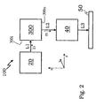
- Fig. 2 shows in a comparable way by means of a schematical block diagram aspects of a conventionally designed image projection device 100 comprising a conventionally designed image generation unit 300.
- an OFF-axis design is demonstrated, i. e. the first or light input/incidence axis/direction Z1 of the primary illumination light L1 and the second or light output/emission axis/direction Z2 of said secondary illumination light L2 being representative for the image to be projected are not arranged or designed to be collinear or essentially collinear, parallel or essentially parallel, or coincident or essentially coincident with respect to each other.
- the reason for that is that the light input/incidence section/surface 300i and the light output/emission section/surface 300o are not in a directly opposing arrangement with respect to each other, but in the Example of Fig. 2 they are essentially perpendicular oriented with respect to each other so that the direction of the travelling light is changed from Z1 for L1 to Z2 for L2 when producing and outputting the image by the conventional image generation unit 300.
- Fig. 3 is a cross-sectional top view of an embodiment of the inventive image generation unit 30.
- a major part of the inventive image generation unit 30 is a polarization selective beam splitting device 10 in the form of a polarization selective beam splitting cube 10.
- This polarization selective beam splitting device 10 or cube 10 comprises a light input/incidence section/surface 10i and a directly opposing and parallely aligned output/emission section/surface 10o.
- the light input/incidence surface/section 10i of the inventive image generation unit 10 at least partly forms the light input/incidence section/surface 30i of the image generation unit 30.
- the light output/emission section/surface 10o of the polarization selective beam splitting device 10 or cube 10 at least partly forms a light output/emission section/surface 30o of the image generation unit 30 according to the present invention.
- the polarization selective beam splitting device 10 or cube 10 also comprises a second pair of sections or surfaces 10p and 10c which are different from the first pair of sections or surfaces 10i and 10o and which are also directly opposing with respect to each other.
- This further pair of sections or surfaces 10p and 10c accordingly forms a second pair of sections or surfaces 30p and 30c, respectively, for the image generation unit 30 of the present invention which is different from the first pair of sections or surfaces 30i and 30o of the image generation unit 30.
- the first pair of sections or surfaces 30i, 30o and 10i, 10o is perpendicularly oriented with respect to the second pair of sections or surfaces 30p, 30c and 10p, 10c, respectively.
- the first section or surface 30p of the second pair contains an imager panel element 61 of the reflective type, for instance in the form of an LCD-panel element, or the like. Additionally, the first section/surface 10p of the second pair of the beam splitting device or cube 10 forms at least a part of said first section / surface 30p of the second pair of the image generation unit 30.
- the second section/surface 30c of the second pair of the image generation unit 30 contains as further elements of the image generation element arrangement 60 a colour-switching device 63 comprising a quarter wave retarder 63-1 and a reflective electronic colour-switching element or RECS 63-2, and finally a reflective arrangement 62 in the form of a mirror 62.
- the second section or surface 10c of the second pair of the beam splitting device or cube 10 forms at least a part of the second section or surface 30c of the second pair of section, areas, surfaces of the inventive image generation unit 30.
- Primary illumination light L1 enters the image generation unit 30 of Fig. 3 via its light input/incidence section/surface 30i.
- Said primary illumination light L1 may be referred to as a superposition of a S-polarized component a P-polarized component.
- the S-polarized component of the primary illumination light L1 is chosen.
- the P-polarized component of such primary illumination light L1 can be absorbed or reflected within the light input/incidence section/surface 30i.
- said light input/incidence section/surface 30i additionally comprises a polarizer 70 by means of which said primary illumination light L1 is completely turned into a S-polarized polarization state.
- the S-polarized primary illumination light L1s is then transmitted through the light input/incidence section/surface 10i of the polarization selective beam splitting device 10 or cube 10 and then transmitted towards the polarization selective beam splitting interface 10s of said polarization selective beam splitting device 10 or cube 10 which is tilted by an angle of 45° against the first or light input/incidence axis/direction Z1 so as to reflect the s-polarized primary illumination light L1s into an Off-axis direction X towards the second section/surface 10c and 30c of the second pair of sections/surfaces of the polarization selective beam splitting device 10 or cube 10 and the inventive image generation unit 30 of Fig. 3 .
- the reflected S-polarized primary illumination light L1s is then still in the S-polarized polarization state and passes through a colour selection arrangement 63 comprising a quarter wave retarder 63-1 and a reflective electronic colour switch 63-2 which are also contained in the second section/area 30c of the second pair of sections/areas of the inventive image generation unit 30 of Fig. 3 .
- the selected colour passes through the colour selection arrangement 63 and is the reflected upon incidence onto a reflective arrangement 62 or mirror 62 also contained in the second section/surface 30c of the second pair of surfaces/sections of the inventive image generation unit 30.
- the polarization state of the reflected light is turned into the P-polarized polarization state and reflected towards the polarization selective beam splitting interface 10s.
- the P-polarized and colour selected light is transmitted to the first section/surface 10p and 30p of the second pair of sections/surfaces of a polarization selected beam splitting device 10 or cube 10 and the inventive image generation unit 30 which is directly opposed to said second section / surface 10c, 30c and parallely oriented thereto.
- the first section/surface 30p of the second pair of sections/surfaces of the inventive image generation unit 30 also contains an imager panel arrangement 61, for instance in the form of a reflective LCD-panel as a further element of the image generation element arrangement 60.
- the incident P-polarized colour selected light Upon incidence onto active areas of the imager panel element 61 the incident P-polarized colour selected light is turned into the S-polarized polarization state which is also called the ON-state and then reflected back to the polarization selective beam splitting interface 10s, where it is again reflected in a direction Z2 for the secondary illumination light L2 which is essentially parallel to the direction Z1 of the incident primary illumination light L2.
- an analyzer 80 is contained which transmits S-polarized light components and which absorbs or reflects P-polarized components.
- p-polarized colour-selected light incident onto non-active areas of the imager panel element 61 is reflected without being changed with respect to its polarization state.
- the p-polarized light component therefore is transmitted through the polarization selective beam splitting interface 10s, falls onto the reflective arrangement 62 or the mirror 62 again, upon said reflection its polarization state is turned into s-polarized polarization state, then reflected back to the polarization selective beam splitting interface 10s and upon incidence onto said polarization selective beam splitting interface 10s back to the origin of the primary illumination light L1.
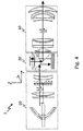
- FIGs. 4 and 5 demonstrate in more detail the structures and elements already shown in Figs. 1 and 2 .
- Fig. 4 shows a detailed example rod like projection engine.
- the light is guided first to the color generating unit and than to the imager.
- the imager is the only part in the telecentric light path of the system.
- the illumination part is denoted with lamp and reflector, first and second lens array, polarizing converting system, main condenser lens.
- the assembly of imager, field lens, reflective electronic color switch and polarizing beam splitting cube are denoted with attached polarizers at sides 1 and 2.
- Fig. 5 shows a state of the art system with 90° tilted optical axis.
- transmissive color switch or a color wheel known from DLP-projectors are used for color generating.
- Fig. 6A and 6B demonstrate more concrete realizations of a quarter wave retarder and of a reflective electronic colour switch, respectively, how they work and how they can be controlled.
- the function is comparable to a mirror plate with a quarter wave retarder ( Fig. 6A ) in front with its first axis turned on 45°.
Landscapes
- Physics & Mathematics (AREA)
- Engineering & Computer Science (AREA)
- Multimedia (AREA)
- Signal Processing (AREA)
- General Physics & Mathematics (AREA)
- Optics & Photonics (AREA)
- Projection Apparatus (AREA)
- Transforming Electric Information Into Light Information (AREA)
- Video Image Reproduction Devices For Color Tv Systems (AREA)
Claims (8)
- Bilderzeugungseinheit (30) mit:- einer und nur einer polarisationsselektiven Strahlteilungseinrichtung (10) in Form eines Strahlteilungswürfels (10) mit einer polarisationsselektiven Strahlteilungsgrenzfläche (10s), die dafür ausgelegt ist, Licht von einem ersten, s-polarisierten Polarisationszustand zu reflektieren, und die dafür ausgelegt ist, Licht von einem zweiten, p-polarisierten Polarisationszustand zu übermitteln, wobei die polarisationsselektive Strahlteilungseinrichtung (10) ein erstes Paar sich gegenüberliegender Flächen (10i, 10o) aufweist, welche eine Lichteingabeoberfläche (10i) und eine Lichtausgabeoberfläche (10o) aufweisen, wobei die Lichteingabeoberfläche (10i) dafür ausgelegt ist, primäres Beleuchtungslicht (L1) entlang einer Lichteinfallsachse (Z1) zu empfangen, und- einer Bilderzeugungselementanordnung (60), welche dafür ausgelegt ist, ein Bild (I) zu produzieren, indem das primäre Beleuchtungslicht (L1) dazu verwendet wird, ein sekundäres Beleuchtungslicht (L2) zu erzeugen,- wobei die Lichtausgabeoberfläche (10o) dafür ausgelegt ist, das sekundäre Beleuchtungslicht (L2) zu emittieren, welches dem Bild entlang einer Bildemissionsachse (Z2) entspricht,- wobei die Lichteinfallsachse (Z1) und die Bildemissionsachse (Z2) kollinear oder zusammenfallend sind,- wobei die Bilderzeugungselementanordnung (60) außerhalb eines durch die ersten und zweiten Achsen (Z1, Z2) definierten Weges oder Durchgangs sowie außerhalb der Polarisationsstrahlteilungseinrichtung (10) angeordnet ist, und- wobei während seinem Durchlaufen der Bilderzeugungseinheit das Licht dreimal auf die polarisationsselektive Strahlteilungsgrenzfläche (10s) einfällt.
- Bilderzeugungseinheit gemäß Anspruch 1, wobei die Bilderzeugungsanordnung (60) ein Bildwandelelement (61), ein reflektierendes Bildwandelelement (61) oder eine LCD-Tafel aufweist, mit denen jeweils ein Bild auf gesteuerte Weise erzeugbar ist.
- Bilderzeugungseinheit gemäß einem der vorangehenden Ansprüche, wobei die Bilderzeugungselementvorrichtung (60) eine reflektierende Anordnung (62) oder einen Spiegel (62) aufweist, die jeweils dafür ausgelegt sind, von der polarisationsselektiven Strahlteilungsgrenzfläche (10s) reflektiertes Licht zu empfangen und dieses Licht zurück zu reflektieren, wobei dessen Polarisationszustand von p nach s oder von s nach p verändert wird.
- Bilderzeugungseinheit gemäß einem der vorangehenden Ansprüche, wobei die Bilderzeugungselementanordnung (60) ein Farbumschalteelement (63) aufweist, welches dafür ausgelegt ist, wenigstens eine erste Spektralkomponente von einfallendem Licht auf gesteuerte Weise zu erzeugen und eine Übertragung des komplementären Spektralbereichs des wenigstens einen ersten Spektralbereichs im Wesentlichen zu vermeiden.
- Bilderzeugungseinheit gemäß Anspruch 4, wobei das Farbumschalteelement (63) ein Viertelwellenverzögerer (63-2) ist oder einen solchen aufweist und/oder ein reflektierender elektronischer Farbschalter (63-2) ist oder einen solchen aufweist.
- Bilderzeugungseinheit gemäß einem der Ansprüche 2 bis 4, wobei einerseits das Bildwandelelement (61) sowie andererseits die reflektierende Anordnung (62) zusammen mit dem Farbumschalteelement (63) an oder in einem zweiten Paar von sich gegenüberliegenden Abschnitten (10p, 10c; 30p, 30c) angeordnet sind, die sich von der Lichteingabeoberfläche (10i) und der Lichtausgabeoberfläche (10o) der polarisationsselektiven Strahlteilungseinrichtung (10) unterscheiden.
- Bilderzeugungseinheit gemäß Anspruch 6, wobei die sich gegenüberliegenden Abschnitte (10p, 10c; 30p, 30c) der polarisationsselektiven Strahlteilungseinrichtung (10) bezüglich der Lichteingabeoberfläche (10i) und der Lichtausgabeoberfläche (10o) der polarisationsselektiven Strahlteilungseinrichtung (10) senkrecht orientiert sind.
- Bildprojektionsvorrichtung mit:- einer Beleuchtungseinheit (20), welche zum Erzeugen eines primären Beleuchtungslichts (L1) angeordnet ist,- einer Bilderzeugungseinheit (30), welche zum Empfangen des primären Beleuchtungslichts (L1) und zum Erzeugen und Emittieren eines Bildes (I) angeordnet ist, und- einer Projektionseinheit (40), welche zum Empfangen und Projizieren des Bildes (I) angeordnet ist,- wobei die Bilderzeugungseinheit (30) gemäß einem der vorangehenden Ansprüche 1 bis 7 ausgebildet ist.
Priority Applications (5)
| Application Number | Priority Date | Filing Date | Title |
|---|---|---|---|
| DE60323384T DE60323384D1 (de) | 2003-12-23 | 2003-12-23 | Bilderzeugungseinheit und Bildprojektionsvorrichtung |
| EP03029805A EP1549081B1 (de) | 2003-12-23 | 2003-12-23 | Bilderzeugungseinheit und Bildprojektionsvorrichtung |
| PCT/EP2004/014504 WO2005064949A1 (en) | 2003-12-23 | 2004-12-20 | Image generation unit and image projection device |
| US10/584,056 US7976165B2 (en) | 2003-12-23 | 2004-12-20 | Image generation unit and image projection device |
| JP2006546026A JP2007527547A (ja) | 2003-12-23 | 2004-12-20 | 画像生成ユニット及び画像投写装置 |
Applications Claiming Priority (1)
| Application Number | Priority Date | Filing Date | Title |
|---|---|---|---|
| EP03029805A EP1549081B1 (de) | 2003-12-23 | 2003-12-23 | Bilderzeugungseinheit und Bildprojektionsvorrichtung |
Publications (2)
| Publication Number | Publication Date |
|---|---|
| EP1549081A1 EP1549081A1 (de) | 2005-06-29 |
| EP1549081B1 true EP1549081B1 (de) | 2008-09-03 |
Family
ID=34530729
Family Applications (1)
| Application Number | Title | Priority Date | Filing Date |
|---|---|---|---|
| EP03029805A Expired - Lifetime EP1549081B1 (de) | 2003-12-23 | 2003-12-23 | Bilderzeugungseinheit und Bildprojektionsvorrichtung |
Country Status (5)
| Country | Link |
|---|---|
| US (1) | US7976165B2 (de) |
| EP (1) | EP1549081B1 (de) |
| JP (1) | JP2007527547A (de) |
| DE (1) | DE60323384D1 (de) |
| WO (1) | WO2005064949A1 (de) |
Families Citing this family (7)
| Publication number | Priority date | Publication date | Assignee | Title |
|---|---|---|---|---|
| US6980346B1 (en) * | 2004-09-15 | 2005-12-27 | Hewlett-Packard Development Company, L.P. | Display device |
| TWI333592B (en) * | 2007-04-19 | 2010-11-21 | Coretronic Corp | Projection apparatus |
| US8087785B2 (en) * | 2008-02-25 | 2012-01-03 | Young Optics Inc. | Projection display apparatus |
| JP5363061B2 (ja) * | 2008-10-10 | 2013-12-11 | 富士フイルム株式会社 | 単板投写型表示装置 |
| JP2010217818A (ja) * | 2009-03-19 | 2010-09-30 | Panasonic Corp | 投写型表示装置 |
| TWI424250B (zh) * | 2010-05-24 | 2014-01-21 | Young Optics Inc | 投影裝置 |
| CN107870438B (zh) | 2017-12-04 | 2019-11-22 | 华为技术有限公司 | 增强现实的装置、光引擎部件和方法 |
Family Cites Families (7)
| Publication number | Priority date | Publication date | Assignee | Title |
|---|---|---|---|---|
| US5042921A (en) * | 1988-10-25 | 1991-08-27 | Casio Computer Co., Ltd. | Liquid crystal display apparatus |
| EP1063852A2 (de) * | 1999-06-21 | 2000-12-27 | Sony Corporation | Bildprojektor |
| TW426163U (en) * | 2000-04-14 | 2001-03-11 | Primax Electronics Ltd | Projection apparatus uses dichromic lens set to complete color separation and color synthesis |
| KR100357716B1 (ko) * | 2000-11-02 | 2002-10-25 | 삼성전자 주식회사 | 전자적으로 제어되는 컬러 스위치를 갖는 광투사 시스템 |
| JP2003121925A (ja) * | 2001-10-11 | 2003-04-23 | Minolta Co Ltd | 投射型表示装置 |
| US20030223044A1 (en) * | 2002-06-04 | 2003-12-04 | Koninklijke Philips Electronics N.V. | Light valve projection system |
| US6779893B2 (en) * | 2003-01-24 | 2004-08-24 | Intel Corporation | Non-collinear light engine for color imaging systems |
-
2003
- 2003-12-23 EP EP03029805A patent/EP1549081B1/de not_active Expired - Lifetime
- 2003-12-23 DE DE60323384T patent/DE60323384D1/de not_active Expired - Lifetime
-
2004
- 2004-12-20 US US10/584,056 patent/US7976165B2/en not_active Expired - Fee Related
- 2004-12-20 WO PCT/EP2004/014504 patent/WO2005064949A1/en not_active Ceased
- 2004-12-20 JP JP2006546026A patent/JP2007527547A/ja not_active Withdrawn
Also Published As
| Publication number | Publication date |
|---|---|
| JP2007527547A (ja) | 2007-09-27 |
| US20080062519A1 (en) | 2008-03-13 |
| EP1549081A1 (de) | 2005-06-29 |
| WO2005064949A1 (en) | 2005-07-14 |
| US7976165B2 (en) | 2011-07-12 |
| DE60323384D1 (de) | 2008-10-16 |
Similar Documents
| Publication | Publication Date | Title |
|---|---|---|
| US6262851B1 (en) | Double-pass projection displays with separate polarizers and analyzers | |
| JP2010160444A (ja) | 映像投射装置 | |
| US20050157265A1 (en) | Projection display systems for light valves | |
| JP4652112B2 (ja) | 投射型表示装置 | |
| EP1549081B1 (de) | Bilderzeugungseinheit und Bildprojektionsvorrichtung | |
| CN1973552A (zh) | 用于包括反射式显示器的彩色投影引擎的成像单元 | |
| JP2004271654A (ja) | 画像表示装置 | |
| US7377649B2 (en) | Projector arrangement | |
| US6853363B2 (en) | Projection type image display apparatus | |
| JP3603588B2 (ja) | 投影表示装置 | |
| EP1610567B1 (de) | Beleuchtungssystem für eine Einzel-Tafel Projektionsanzeige. | |
| US20060119936A1 (en) | Apparatus and method for color and polarization switching | |
| US20060077350A1 (en) | 3-Panel transmissive projection system | |
| KR100474904B1 (ko) | Pccr 적분기를 갖는 광학계 | |
| JPH05100331A (ja) | 液晶表示装置 | |
| US6831788B2 (en) | Polarization beam splitter and projection display apparatus using the same | |
| KR100404209B1 (ko) | 프로젝터의 광학 시스템 | |
| KR100463525B1 (ko) | Pccr 적분기를 갖는 광학계 | |
| KR100429210B1 (ko) | 단판식 광학 시스템 | |
| KR100474917B1 (ko) | Pccr 적분기와 컬러 스위치를 갖는 광학계 | |
| WO2004046787A1 (en) | Three-panel color management systems and methods | |
| KR100442253B1 (ko) | 고효율 단판식 반사형 광학 장치 | |
| KR20010107125A (ko) | 반사형 액정 프로젝터용 조명 광학계 | |
| KR20020000381A (ko) | 프로젝션 엔진의 광 분리 및 합성 장치 | |
| JPH03114026A (ja) | 液晶ビデオプロジェクター |
Legal Events
| Date | Code | Title | Description |
|---|---|---|---|
| PUAI | Public reference made under article 153(3) epc to a published international application that has entered the european phase |
Free format text: ORIGINAL CODE: 0009012 |
|
| AK | Designated contracting states |
Kind code of ref document: A1 Designated state(s): AT BE BG CH CY CZ DE DK EE ES FI FR GB GR HU IE IT LI LU MC NL PT RO SE SI SK TR |
|
| AX | Request for extension of the european patent |
Extension state: AL LT LV MK |
|
| RAP1 | Party data changed (applicant data changed or rights of an application transferred) |
Owner name: SONY DEUTSCHLAND GMBH |
|
| 17P | Request for examination filed |
Effective date: 20051214 |
|
| AKX | Designation fees paid |
Designated state(s): DE FR GB |
|
| 17Q | First examination report despatched |
Effective date: 20060411 |
|
| RAP1 | Party data changed (applicant data changed or rights of an application transferred) |
Owner name: SONY DEUTSCHLAND GMBH |
|
| GRAP | Despatch of communication of intention to grant a patent |
Free format text: ORIGINAL CODE: EPIDOSNIGR1 |
|
| GRAS | Grant fee paid |
Free format text: ORIGINAL CODE: EPIDOSNIGR3 |
|
| GRAA | (expected) grant |
Free format text: ORIGINAL CODE: 0009210 |
|
| AK | Designated contracting states |
Kind code of ref document: B1 Designated state(s): DE FR GB |
|
| REG | Reference to a national code |
Ref country code: GB Ref legal event code: FG4D |
|
| REF | Corresponds to: |
Ref document number: 60323384 Country of ref document: DE Date of ref document: 20081016 Kind code of ref document: P |
|
| PGFP | Annual fee paid to national office [announced via postgrant information from national office to epo] |
Ref country code: FR Payment date: 20081212 Year of fee payment: 6 |
|
| PGFP | Annual fee paid to national office [announced via postgrant information from national office to epo] |
Ref country code: GB Payment date: 20081217 Year of fee payment: 6 |
|
| PLBE | No opposition filed within time limit |
Free format text: ORIGINAL CODE: 0009261 |
|
| STAA | Information on the status of an ep patent application or granted ep patent |
Free format text: STATUS: NO OPPOSITION FILED WITHIN TIME LIMIT |
|
| 26N | No opposition filed |
Effective date: 20090604 |
|
| GBPC | Gb: european patent ceased through non-payment of renewal fee |
Effective date: 20091223 |
|
| REG | Reference to a national code |
Ref country code: FR Ref legal event code: ST Effective date: 20100831 |
|
| PG25 | Lapsed in a contracting state [announced via postgrant information from national office to epo] |
Ref country code: FR Free format text: LAPSE BECAUSE OF NON-PAYMENT OF DUE FEES Effective date: 20091231 |
|
| PG25 | Lapsed in a contracting state [announced via postgrant information from national office to epo] |
Ref country code: GB Free format text: LAPSE BECAUSE OF NON-PAYMENT OF DUE FEES Effective date: 20091223 |
|
| PGFP | Annual fee paid to national office [announced via postgrant information from national office to epo] |
Ref country code: DE Payment date: 20101222 Year of fee payment: 8 |
|
| REG | Reference to a national code |
Ref country code: DE Ref legal event code: R119 Ref document number: 60323384 Country of ref document: DE Effective date: 20120703 |
|
| PG25 | Lapsed in a contracting state [announced via postgrant information from national office to epo] |
Ref country code: DE Free format text: LAPSE BECAUSE OF NON-PAYMENT OF DUE FEES Effective date: 20120703 |