EP1585324A1 - Liquid crystal television device comprising a recording/reproducing device such as a dvd recorder/player or the like - Google Patents
Liquid crystal television device comprising a recording/reproducing device such as a dvd recorder/player or the like Download PDFInfo
- Publication number
- EP1585324A1 EP1585324A1 EP05251954A EP05251954A EP1585324A1 EP 1585324 A1 EP1585324 A1 EP 1585324A1 EP 05251954 A EP05251954 A EP 05251954A EP 05251954 A EP05251954 A EP 05251954A EP 1585324 A1 EP1585324 A1 EP 1585324A1
- Authority
- EP
- European Patent Office
- Prior art keywords
- circuit
- liquid crystal
- dvd
- circuit board
- recording
- Prior art date
- Legal status (The legal status is an assumption and is not a legal conclusion. Google has not performed a legal analysis and makes no representation as to the accuracy of the status listed.)
- Withdrawn
Links
Images


Classifications
-
- H—ELECTRICITY
- H04—ELECTRIC COMMUNICATION TECHNIQUE
- H04N—PICTORIAL COMMUNICATION, e.g. TELEVISION
- H04N5/00—Details of television systems
- H04N5/64—Constructional details of receivers, e.g. cabinets or dust covers
-
- H—ELECTRICITY
- H05—ELECTRIC TECHNIQUES NOT OTHERWISE PROVIDED FOR
- H05K—PRINTED CIRCUITS; CASINGS OR CONSTRUCTIONAL DETAILS OF ELECTRIC APPARATUS; MANUFACTURE OF ASSEMBLAGES OF ELECTRICAL COMPONENTS
- H05K1/00—Printed circuits
- H05K1/02—Details
- H05K1/14—Structural association of two or more printed circuits
Definitions
- the present invention relates to a liquid crystal television device mounted with a recording/reproducing device such as a DVD or the like, and relates in particular to a liquid crystal television device having characteristic layout construction comprising the multiple circuit boards of a DVD and the liquid crystal display control unit of a television.
- the "recording/reproducing device” refers to a device having a recording function or a reproduction function or a device having a recording function and a reproduction function meeting the specification.
- Liquid crystal television devices provided with a recording/reproducing device such as a DVD, etc. in a television set capable of viewing both DVD reproductions and television broadcasts in one set have heretofore been known, as disclosed in Patent documents 1 to 5.
- a large unit arranged in the liquid crystal television device set is mainly provided with a liquid crystal display device, a liquid crystal television circuit board mounted with a liquid crystal digital control circuit, an analog control circuit of other power supply processing, audio video signal processing, etc. and a DVD circuit board mounted with a control circuit for DVD recording/reproducing device and DVD driving.
- Such a liquid crystal television device including a recording/reproducing device such as a DVD or the like enables enjoying both DVD reproduction and television broadcasts in one liquid crystal display set, but a DVD recording/reproducing device and its control circuit board must be provided in addition to the television display device and its control circuit board, and therefore had to become large in size in comparison with the liquid crystal display set of only a liquid crystal television device.
- the present invention was made in view of such a point and is directed at providing a liquid crystal television device which has a small set and is inexpensive due to the small size and design of the construction of the control circuit boards of a liquid crystal display device including a recording/ reproducing device such as a DVD or the like and its layout construction.
- the present invention was technically based as follows.
- one-side circuit board analog control circuit board of power supply processing, audio video signal processing, etc.
- the multilayer circuit board liquid crystal digital control circuit board
- the present invention is characterized by the fact that three main boards comprising:
- the present invention is preferably characterized by the fact that the television circuit board is a one-side mounting board made of paper, and the circuit board for DVD circuit and the liquid crystal circuit board are multilayer boards.
- the present invention is preferably characterized by the fact that a DVD recording/ reproducing device and the television circuit board are arranged in a plane on the back of the liquid crystal panel unit, and the liquid crystal circuit board and the circuit board for DVD circuit are arranged by putting one board on the other to form a two-story deck in another space.
- the present invention is further preferably characterized by the fact that the circuit board for the DVD circuit is arranged by placing it on the liquid crystal circuit board, and the DVD recording/reproducing device and the circuit board for DVD circuit are linearly connected with a control signal cable and a pickup signal cable, respectively.
- the present invention is characterized by the fact that three main boards comprising:
- the present invention enables to overcoming the problems and drawbacks of the prior art because it can arrange and provide circuit boards which effectively use a space in a display control device set of a liquid crystal television capable of viewing both DVD reproduction and television and does not any cause trouble relative to performance.
- noise relating to radiation can be prevented because the digital control circuit and analog control circuit are separated and mounted on independent circuit boards.
- Fig. 1 is a schematic diagram for illustrating an embodiment of the present invention and showing the state of arranging the circuit boards of the liquid crystal display of a liquid crystal television device which enables viewing both DVD reproduction and television broadcasts.
- Fig. 1 indicates an entire liquid crystal display set of a liquid crystal television device.
- No. 11 is a television circuit board mounted with an analog control circuit for power supply processing/audio video signal processing, etc. and is prepared with a paper one-side board as kind of board at a low cost.
- No. 12 is a circuit board for DVD circuit mounted with a DVD driving control circuit and is made to a multilayer structure.
- No. 13 is a liquid crystal circuit board mounted with a liquid crystal digital control circuit and is also made to be multilayer structure.
- No . 14 is a DVD recording/ reproducing device, and 15 is a liquid crystal panel unit.
- Nos. 16, 16 are left and right speakers.
- a control circuit board for a liquid crystal television in a liquid crystal television mounted with a recording/ reproducing device such as a DVD or the like is designed by separating it into a digital circuit board and an analog circuit board, and designed with consideration to cost and performance, wherein the analog control circuit for power supply/audio-circuit, etc. is mounted and arranged on the one-side television circuit board 11, and the liquid crystal digital control circuit is mounted and arranged on the multilayer circuit board and provided in a display control device set, respectively.
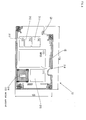
- Fig. 2 Layout construction of the boards in the present invention is clearly shown in Fig. 2.
- the boards are installed in a liquid crystal panel unit cover 16 (expressed as LCD COVER in the diagram) mounted to the rear face of the liquid crystal panel unit 15 (expressed as LCD in the diagram).
- Multiple embossed parts 17, 17, 17... for board installation are formed on the cover 16, and screws are cut into the embossed parts.
- the television circuit board 11 (expressed as MAIN PCB in the diagram) mounted with the analog control circuit for power supply/audio video signal processing, etc.
- the liquid crystal circuit board 13 (expressed as LCD PCB in the diagram) mounted with the liquid crystal digital control circuit are installed on the cover 16.
- the circuit board for DVD circuit 12 mounted with a DVD driving control circuit is installed on embossed parts 19, 19 of a board cover 18 covering the liquid crystal circuit board 13.
- the board cover 18 also has both the function of covering the liquid crystal circuit board 13 and the function of installing the circuit board for DVD circuit 12 and is provided with legs 20, 20 bent at four corners, the legs being bent into an L shape and mounted to the liquid crystal panel unit cover 16 with vises.
- the positional relationships for arranging these boards are expressed by the chain lines shown in Fig. 2. Namely, according to the embodiment of the present invention, three main circuit boards: the television circuit board 11 mounted with the analog control circuit for power supply/audio-circuit, etc., the liquid crystal circuit board 13 mounted with the liquid crystal digital control circuit and the DVD circuit board 12 mounted with the DVD driving control circuit are provided on the liquid crystal panel unit 15 in the liquid crystal display set of the liquid crystal television device.
- the television circuit board 11 has been designed with a paper one-side circuit board, but a "circuit having an analog control function of power supply/audio-circuit, etc.”, except for a "circuit of a liquid crystal digital control function" which is mounted in the multilayer circuit board designed with the multilayer circuit board of the prior art, is mounted, therefore the size of the circuit board is not larger than the size of the circuit board for the liquid crystal television in the prior art, and the circuit arrangement of the television circuit board 11 mounted with the analog control circuit such as power supply/ audio-circuit, etc. can be arranged in a space nearly the same as the arrangement in liquid crystal television device of the prior art. Namely, the television circuit board 11 is received in a size capable of loading it onto a rear face of a liquid crystal panel unit of conventional size.
- FIG. 3 A layout diagram of the specific functional circuits of the one-side television circuit board 11 mounted with the analog control circuit such as power supply/audio-circuit, etc. is shown in Fig. 3.
- This analog circuit board 11 is prepared inexpensively with a paper one-side board, input/output terminals such as a digital audio output terminal 119, an antenna input terminal 120, a DC input terminal 121, a digital RGB input terminal 122, an AV input terminal 123, an S input terminal 124 and a component input terminal 125 are arranged at the end face of board.
- a tuner 111 (expressed as ( 1 ) in the diagram) is arranged by laying it down in the vicinity of the antenna input terminal 120.
- a circuit of power supply processing function 126 (expressed as (14) in the diagram) of a transformer or many condensers (non-illustrated) is arranged near the end face of the board in the vicinity of the DC input terminal 121 and digital RGB input terminal 122.
- a circuit of the audio multiplex processing function 112 (expressed as (2) in the diagram), a circuit of audio output 114 (expressed as (4) in the diagram) and a circuit of the audio output processing function 115 (expressed as (5) in the diagram) are arranged at the rear of the circuit of the power supply processing function 126.
- a circuit of audio input switch processing function 113 (expressed as (3) in the diagram) and a circuit of the video switch processing function 116 (expressed as (6) in the diagram) are arranged in the vicinity of the AV input terminal 123, S input terminal 124 and component input terminal 125.
- a circuit of the microcomputer processing function 117 (expressed as (7) in the diagram) and a memory part 118 (expressed as (8) in the diagram) are arranged at the rear thereof.
- the television circuit board 11 can be arranged in a space nearly the same as the layout in a prior art set, even if it is taken as a one-side board made of paper, because the television circuit board 11 is used as the board construction for analog processing circuit. Therefore the liquid crystal circuit board 13 mounted with the liquid crystal digital control circuit and the DVD circuit board 12 mounted with the DVD driving control circuit can be arranged at the back of the liquid crystal panel unit 15 except for installing the television circuit board 11. At this time, the DVD circuit board 12 and the liquid crystal circuit board 13 are arranged by putting one board on the other to form a two-story deck. Hence, the size of the liquid crystal television device is not larger than the size of a prior art liquid crystal television.
- the DVD circuit board 12 and the liquid crystal circuit board 13 are arranged by putting one board on the other so that they become lower than the height of DVD recording/ reproducing device 14 in a space of the back of liquid crystal panel except for the position for installing the television circuit board 11. Moreover, if the DVD driving circuit board 12 is arranged by placing it above the liquid crystal circuit board 13, in a case of liquid crystal television single model, a thinner liquid crystal television single device set can be obtained by constructing the device without installing the DVD circuit board 12 and the DVD recording/ reproducing device 14.
- the DVD circuit board 12 is prepared with a multilayer board, an audio signal processing function circuit 211 (expressed as (16) in the diagram), an video signal storage function circuit 212 (expressed as (14) in the diagram) and a control signal storage function circuit 213 (expressed as (13) in the diagram) arranged on the board.
- An MPEG processing function circuit 214 (expressed as (15) in the diagram) is arranged in the central part of the board, a pickup signal processing function circuit 215 (expressed as (11) in the diagram) and a motor control function circuit 216 (expressed as (12) in the diagram) are further arranged on the board.
- the liquid crystal circuit board 13 is prepared with a multilayer board, an video signal conversion function circuit 311 (expressed as (9) in the diagram) comprising an analog-digital conversion function circuit, an I/P conversion function circuit and a SCALER function circuit and an video signal conversion auxiliary function circuit 312 (expressed as (10) in the diagram) are arranged on the board.
- an video signal conversion function circuit 311 (expressed as (9) in the diagram) comprising an analog-digital conversion function circuit, an I/P conversion function circuit and a SCALER function circuit and an video signal conversion auxiliary function circuit 312 (expressed as (10) in the diagram) are arranged on the board.
- the relation of installation positions of the DVD recording/reproducing device 14 and the DVD circuit board 12 is shown in Fig. 6.
- the DVD recording/ reproducing device 14 and the DVD circuit board 12 are connected by a control signal cable 19 and a pickup signal cable 20 for exchanging signals for the motor drive of the DVD recording/ reproducing device and for exchanging audio video information signals, etc. for information recording/production.
- a control signal cable connector 21 and a pickup signal cable connector 22 on the DVD circuit board 12 are arranged to match the control signal fetch position and the pickup signal fetch position on the DVD recording/ reproducing device 14 side, linearly arranging both of the cables 19, 20.
- the present invention has the construction as described above and uses the following working effects.
Landscapes
- Engineering & Computer Science (AREA)
- Multimedia (AREA)
- Signal Processing (AREA)
- Devices For Indicating Variable Information By Combining Individual Elements (AREA)
- Mounting Of Printed Circuit Boards And The Like (AREA)
- Liquid Crystal Display Device Control (AREA)
Applications Claiming Priority (2)
| Application Number | Priority Date | Filing Date | Title |
|---|---|---|---|
| JP2004106295A JP2005295146A (ja) | 2004-03-31 | 2004-03-31 | Dvd等の記録再生装置を搭載した液晶テレビジョン装置 |
| JP2004106295 | 2004-03-31 |
Publications (1)
| Publication Number | Publication Date |
|---|---|
| EP1585324A1 true EP1585324A1 (en) | 2005-10-12 |
Family
ID=34909451
Family Applications (1)
| Application Number | Title | Priority Date | Filing Date |
|---|---|---|---|
| EP05251954A Withdrawn EP1585324A1 (en) | 2004-03-31 | 2005-03-30 | Liquid crystal television device comprising a recording/reproducing device such as a dvd recorder/player or the like |
Country Status (3)
| Country | Link |
|---|---|
| US (1) | US20050220443A1 (enExample) |
| EP (1) | EP1585324A1 (enExample) |
| JP (1) | JP2005295146A (enExample) |
Cited By (3)
| Publication number | Priority date | Publication date | Assignee | Title |
|---|---|---|---|---|
| EP1577894A3 (en) * | 2004-03-19 | 2008-01-09 | ORION ELECTRIC CO., Ltd. | Liquid crystal display device with built-in disk device |
| EP1798967A3 (en) * | 2005-12-14 | 2008-03-05 | ORION ELECTRIC CO., Ltd. | Display device |
| EP1860521A3 (en) * | 2006-05-24 | 2012-12-05 | Funai Electric Co., Ltd. | Liquid crystal display device |
Families Citing this family (1)
| Publication number | Priority date | Publication date | Assignee | Title |
|---|---|---|---|---|
| US10582620B2 (en) | 2015-01-19 | 2020-03-03 | Mitsubishi Electric Corporation | Controller |
Citations (3)
| Publication number | Priority date | Publication date | Assignee | Title |
|---|---|---|---|---|
| US4581654A (en) * | 1982-08-04 | 1986-04-08 | Casio Computer Co., Ltd. | Portable television receiver of the panel type |
| US5923870A (en) * | 1996-09-30 | 1999-07-13 | Monorail, Inc. | Computer having a life-time counter |
| EP1382991A2 (en) * | 2002-07-16 | 2004-01-21 | Samsung Electronics Co., Ltd. | Display apparatus |
Family Cites Families (5)
| Publication number | Priority date | Publication date | Assignee | Title |
|---|---|---|---|---|
| US4654965A (en) * | 1984-07-16 | 1987-04-07 | Ricoh Company, Ltd. | Method of manufacturing liquid crystal display unit |
| US5822030A (en) * | 1994-09-16 | 1998-10-13 | Seiko Epson Corporation | Liquid crystal display device, its mounting structure and electronic device |
| US7084932B1 (en) * | 1999-12-28 | 2006-08-01 | Johnson Controls Technology Company | Video display system for a vehicle |
| JP2004159191A (ja) * | 2002-11-07 | 2004-06-03 | Seiko Epson Corp | 画像データに応じたフレームレートの変換 |
| US20050007500A1 (en) * | 2003-03-28 | 2005-01-13 | Yet-Zen Lin | Liquid crystal display with changeable modules |
-
2004
- 2004-03-31 JP JP2004106295A patent/JP2005295146A/ja not_active Withdrawn
-
2005
- 2005-03-30 EP EP05251954A patent/EP1585324A1/en not_active Withdrawn
- 2005-03-30 US US11/093,055 patent/US20050220443A1/en not_active Abandoned
Patent Citations (3)
| Publication number | Priority date | Publication date | Assignee | Title |
|---|---|---|---|---|
| US4581654A (en) * | 1982-08-04 | 1986-04-08 | Casio Computer Co., Ltd. | Portable television receiver of the panel type |
| US5923870A (en) * | 1996-09-30 | 1999-07-13 | Monorail, Inc. | Computer having a life-time counter |
| EP1382991A2 (en) * | 2002-07-16 | 2004-01-21 | Samsung Electronics Co., Ltd. | Display apparatus |
Non-Patent Citations (1)
| Title |
|---|
| "Maintenance and Service Guide, Compaq Evo Notebook N1005 Series", November 2002, COMPAQ INFORMATION TECHNOLOGIES GOUP, L.P., XP002338855 * |
Cited By (3)
| Publication number | Priority date | Publication date | Assignee | Title |
|---|---|---|---|---|
| EP1577894A3 (en) * | 2004-03-19 | 2008-01-09 | ORION ELECTRIC CO., Ltd. | Liquid crystal display device with built-in disk device |
| EP1798967A3 (en) * | 2005-12-14 | 2008-03-05 | ORION ELECTRIC CO., Ltd. | Display device |
| EP1860521A3 (en) * | 2006-05-24 | 2012-12-05 | Funai Electric Co., Ltd. | Liquid crystal display device |
Also Published As
| Publication number | Publication date |
|---|---|
| US20050220443A1 (en) | 2005-10-06 |
| JP2005295146A (ja) | 2005-10-20 |
Similar Documents
| Publication | Publication Date | Title |
|---|---|---|
| JP5201964B2 (ja) | 画像表示装置 | |
| US20070133158A1 (en) | Display device | |
| EP1585324A1 (en) | Liquid crystal television device comprising a recording/reproducing device such as a dvd recorder/player or the like | |
| US8223504B2 (en) | Structure for supporting printed wiring board | |
| CN101060345B (zh) | 广播接收装置及其调谐装置和用于其的分配器 | |
| US7466541B2 (en) | Liquid crystal display device | |
| JP2006259225A (ja) | Lcdカバーを備える液晶表示装置 | |
| JP2007265640A (ja) | 液晶パネル用ケーブル、及び液晶ディスプレイテレビ | |
| US20040180574A1 (en) | Stacked connector assembly | |
| JP3632915B2 (ja) | 基板配線体 | |
| JP3301543B2 (ja) | 液晶テレビの組立構造 | |
| US20050213042A1 (en) | Liquid crystal display device | |
| US20070201841A1 (en) | Liquid crystal television receiver | |
| JP5163790B2 (ja) | 回路基板の固定構造及び記録媒体再生装置 | |
| US20060170663A1 (en) | Analog/digital recording and playback device, and display device | |
| EP2034744A1 (en) | Display apparatus and multi display apparatus having the same | |
| JP3159766U (ja) | 表示装置 | |
| JP5261957B2 (ja) | 映像表示装置 | |
| US20060098152A1 (en) | Display apparatus | |
| JP2013093815A (ja) | 電子機器、映像表示装置及びテレビジョン放送受信機 | |
| JP2555947Y2 (ja) | 端子構造 | |
| JP3109873U (ja) | 回路基板装置 | |
| JPH09167895A (ja) | 電気機器の保護カバー付回路基板収容構造 | |
| JP2006066035A (ja) | 複合映像記憶再生機器 | |
| JPH0145176Y2 (enExample) |
Legal Events
| Date | Code | Title | Description |
|---|---|---|---|
| PUAI | Public reference made under article 153(3) epc to a published international application that has entered the european phase |
Free format text: ORIGINAL CODE: 0009012 |
|
| AK | Designated contracting states |
Kind code of ref document: A1 Designated state(s): AT BE BG CH CY CZ DE DK EE ES FI FR GB GR HU IE IS IT LI LT LU MC NL PL PT RO SE SI SK TR |
|
| AX | Request for extension of the european patent |
Extension state: AL BA HR LV MK YU |
|
| 17P | Request for examination filed |
Effective date: 20060113 |
|
| AKX | Designation fees paid |
Designated state(s): DE FR GB |
|
| STAA | Information on the status of an ep patent application or granted ep patent |
Free format text: STATUS: THE APPLICATION HAS BEEN WITHDRAWN |
|
| 18W | Application withdrawn |
Effective date: 20080916 |