EP1584809A1 - Procédé et dispositif pour régénération d'un équipement de post traitement des gaz d'échappement - Google Patents
Procédé et dispositif pour régénération d'un équipement de post traitement des gaz d'échappement Download PDFInfo
- Publication number
- EP1584809A1 EP1584809A1 EP05104883A EP05104883A EP1584809A1 EP 1584809 A1 EP1584809 A1 EP 1584809A1 EP 05104883 A EP05104883 A EP 05104883A EP 05104883 A EP05104883 A EP 05104883A EP 1584809 A1 EP1584809 A1 EP 1584809A1
- Authority
- EP
- European Patent Office
- Prior art keywords
- temperature
- post
- injection
- internal combustion
- combustion engine
- Prior art date
- Legal status (The legal status is an assumption and is not a legal conclusion. Google has not performed a legal analysis and makes no representation as to the accuracy of the status listed.)
- Granted
Links
- 230000008929 regeneration Effects 0.000 title claims abstract description 23
- 238000011069 regeneration method Methods 0.000 title claims abstract description 23
- 238000000034 method Methods 0.000 title claims abstract description 11
- 238000002347 injection Methods 0.000 claims abstract description 113
- 239000007924 injection Substances 0.000 claims abstract description 113
- 239000000446 fuel Substances 0.000 claims abstract description 33
- 239000007789 gas Substances 0.000 claims description 56
- 238000002485 combustion reaction Methods 0.000 claims description 39
- 238000012937 correction Methods 0.000 claims description 34
- 229930195733 hydrocarbon Natural products 0.000 claims description 18
- 150000002430 hydrocarbons Chemical class 0.000 claims description 18
- 229910052760 oxygen Inorganic materials 0.000 claims description 14
- 239000001301 oxygen Substances 0.000 claims description 14
- QVGXLLKOCUKJST-UHFFFAOYSA-N atomic oxygen Chemical compound [O] QVGXLLKOCUKJST-UHFFFAOYSA-N 0.000 claims description 11
- 239000002245 particle Substances 0.000 claims description 11
- 230000001105 regulatory effect Effects 0.000 claims description 10
- 239000004215 Carbon black (E152) Substances 0.000 claims description 6
- 238000005259 measurement Methods 0.000 claims 1
- 230000001172 regenerating effect Effects 0.000 claims 1
- 230000001419 dependent effect Effects 0.000 abstract description 9
- 230000008569 process Effects 0.000 abstract description 2
- 230000001052 transient effect Effects 0.000 description 29
- 239000003054 catalyst Substances 0.000 description 15
- 239000003570 air Substances 0.000 description 12
- 239000002816 fuel additive Substances 0.000 description 8
- 238000010586 diagram Methods 0.000 description 6
- 206010053615 Thermal burn Diseases 0.000 description 5
- 238000009529 body temperature measurement Methods 0.000 description 4
- 238000006243 chemical reaction Methods 0.000 description 4
- 238000010438 heat treatment Methods 0.000 description 4
- MYMOFIZGZYHOMD-UHFFFAOYSA-N Dioxygen Chemical compound O=O MYMOFIZGZYHOMD-UHFFFAOYSA-N 0.000 description 3
- 239000000498 cooling water Substances 0.000 description 3
- 230000003647 oxidation Effects 0.000 description 3
- 238000007254 oxidation reaction Methods 0.000 description 3
- 239000004071 soot Substances 0.000 description 3
- OKTJSMMVPCPJKN-UHFFFAOYSA-N Carbon Chemical compound [C] OKTJSMMVPCPJKN-UHFFFAOYSA-N 0.000 description 2
- 239000012080 ambient air Substances 0.000 description 2
- 229910052799 carbon Inorganic materials 0.000 description 2
- 230000003197 catalytic effect Effects 0.000 description 2
- 230000007613 environmental effect Effects 0.000 description 2
- 230000007935 neutral effect Effects 0.000 description 2
- 230000000638 stimulation Effects 0.000 description 2
- 238000011144 upstream manufacturing Methods 0.000 description 2
- 238000013459 approach Methods 0.000 description 1
- 230000015572 biosynthetic process Effects 0.000 description 1
- 230000008859 change Effects 0.000 description 1
- 238000006477 desulfuration reaction Methods 0.000 description 1
- 230000023556 desulfurization Effects 0.000 description 1
- 238000011161 development Methods 0.000 description 1
- 230000018109 developmental process Effects 0.000 description 1
- 238000010790 dilution Methods 0.000 description 1
- 239000012895 dilution Substances 0.000 description 1
- 238000001914 filtration Methods 0.000 description 1
- 239000000295 fuel oil Substances 0.000 description 1
- 238000004519 manufacturing process Methods 0.000 description 1
- 239000000203 mixture Substances 0.000 description 1
- 238000002360 preparation method Methods 0.000 description 1
- 230000004044 response Effects 0.000 description 1
- 230000035945 sensitivity Effects 0.000 description 1
- 238000003860 storage Methods 0.000 description 1
- 230000007704 transition Effects 0.000 description 1
Images
Classifications
-
- F—MECHANICAL ENGINEERING; LIGHTING; HEATING; WEAPONS; BLASTING
- F02—COMBUSTION ENGINES; HOT-GAS OR COMBUSTION-PRODUCT ENGINE PLANTS
- F02D—CONTROLLING COMBUSTION ENGINES
- F02D41/00—Electrical control of supply of combustible mixture or its constituents
- F02D41/30—Controlling fuel injection
- F02D41/38—Controlling fuel injection of the high pressure type
- F02D41/40—Controlling fuel injection of the high pressure type with means for controlling injection timing or duration
- F02D41/402—Multiple injections
- F02D41/405—Multiple injections with post injections
-
- F—MECHANICAL ENGINEERING; LIGHTING; HEATING; WEAPONS; BLASTING
- F02—COMBUSTION ENGINES; HOT-GAS OR COMBUSTION-PRODUCT ENGINE PLANTS
- F02D—CONTROLLING COMBUSTION ENGINES
- F02D41/00—Electrical control of supply of combustible mixture or its constituents
- F02D41/02—Circuit arrangements for generating control signals
- F02D41/021—Introducing corrections for particular conditions exterior to the engine
- F02D41/0235—Introducing corrections for particular conditions exterior to the engine in relation with the state of the exhaust gas treating apparatus
- F02D41/027—Introducing corrections for particular conditions exterior to the engine in relation with the state of the exhaust gas treating apparatus to purge or regenerate the exhaust gas treating apparatus
- F02D41/029—Introducing corrections for particular conditions exterior to the engine in relation with the state of the exhaust gas treating apparatus to purge or regenerate the exhaust gas treating apparatus the exhaust gas treating apparatus being a particulate filter
-
- F—MECHANICAL ENGINEERING; LIGHTING; HEATING; WEAPONS; BLASTING
- F02—COMBUSTION ENGINES; HOT-GAS OR COMBUSTION-PRODUCT ENGINE PLANTS
- F02D—CONTROLLING COMBUSTION ENGINES
- F02D41/00—Electrical control of supply of combustible mixture or its constituents
- F02D41/30—Controlling fuel injection
- F02D41/38—Controlling fuel injection of the high pressure type
- F02D2041/389—Controlling fuel injection of the high pressure type for injecting directly into the cylinder
-
- F—MECHANICAL ENGINEERING; LIGHTING; HEATING; WEAPONS; BLASTING
- F02—COMBUSTION ENGINES; HOT-GAS OR COMBUSTION-PRODUCT ENGINE PLANTS
- F02D—CONTROLLING COMBUSTION ENGINES
- F02D2200/00—Input parameters for engine control
- F02D2200/02—Input parameters for engine control the parameters being related to the engine
- F02D2200/04—Engine intake system parameters
- F02D2200/0406—Intake manifold pressure
-
- F—MECHANICAL ENGINEERING; LIGHTING; HEATING; WEAPONS; BLASTING
- F02—COMBUSTION ENGINES; HOT-GAS OR COMBUSTION-PRODUCT ENGINE PLANTS
- F02D—CONTROLLING COMBUSTION ENGINES
- F02D2200/00—Input parameters for engine control
- F02D2200/02—Input parameters for engine control the parameters being related to the engine
- F02D2200/04—Engine intake system parameters
- F02D2200/0414—Air temperature
-
- F—MECHANICAL ENGINEERING; LIGHTING; HEATING; WEAPONS; BLASTING
- F02—COMBUSTION ENGINES; HOT-GAS OR COMBUSTION-PRODUCT ENGINE PLANTS
- F02D—CONTROLLING COMBUSTION ENGINES
- F02D2200/00—Input parameters for engine control
- F02D2200/70—Input parameters for engine control said parameters being related to the vehicle exterior
- F02D2200/703—Atmospheric pressure
-
- F—MECHANICAL ENGINEERING; LIGHTING; HEATING; WEAPONS; BLASTING
- F02—COMBUSTION ENGINES; HOT-GAS OR COMBUSTION-PRODUCT ENGINE PLANTS
- F02D—CONTROLLING COMBUSTION ENGINES
- F02D41/00—Electrical control of supply of combustible mixture or its constituents
- F02D41/02—Circuit arrangements for generating control signals
- F02D41/021—Introducing corrections for particular conditions exterior to the engine
- F02D41/0235—Introducing corrections for particular conditions exterior to the engine in relation with the state of the exhaust gas treating apparatus
- F02D41/024—Introducing corrections for particular conditions exterior to the engine in relation with the state of the exhaust gas treating apparatus to increase temperature of the exhaust gas treating apparatus
- F02D41/0245—Introducing corrections for particular conditions exterior to the engine in relation with the state of the exhaust gas treating apparatus to increase temperature of the exhaust gas treating apparatus by increasing temperature of the exhaust gas leaving the engine
-
- F—MECHANICAL ENGINEERING; LIGHTING; HEATING; WEAPONS; BLASTING
- F02—COMBUSTION ENGINES; HOT-GAS OR COMBUSTION-PRODUCT ENGINE PLANTS
- F02D—CONTROLLING COMBUSTION ENGINES
- F02D41/00—Electrical control of supply of combustible mixture or its constituents
- F02D41/02—Circuit arrangements for generating control signals
- F02D41/021—Introducing corrections for particular conditions exterior to the engine
- F02D41/0235—Introducing corrections for particular conditions exterior to the engine in relation with the state of the exhaust gas treating apparatus
- F02D41/024—Introducing corrections for particular conditions exterior to the engine in relation with the state of the exhaust gas treating apparatus to increase temperature of the exhaust gas treating apparatus
- F02D41/025—Introducing corrections for particular conditions exterior to the engine in relation with the state of the exhaust gas treating apparatus to increase temperature of the exhaust gas treating apparatus by changing the composition of the exhaust gas, e.g. for exothermic reaction on exhaust gas treating apparatus
-
- F—MECHANICAL ENGINEERING; LIGHTING; HEATING; WEAPONS; BLASTING
- F02—COMBUSTION ENGINES; HOT-GAS OR COMBUSTION-PRODUCT ENGINE PLANTS
- F02D—CONTROLLING COMBUSTION ENGINES
- F02D41/00—Electrical control of supply of combustible mixture or its constituents
- F02D41/02—Circuit arrangements for generating control signals
- F02D41/04—Introducing corrections for particular operating conditions
- F02D41/10—Introducing corrections for particular operating conditions for acceleration
- F02D41/107—Introducing corrections for particular operating conditions for acceleration and deceleration
-
- F—MECHANICAL ENGINEERING; LIGHTING; HEATING; WEAPONS; BLASTING
- F02—COMBUSTION ENGINES; HOT-GAS OR COMBUSTION-PRODUCT ENGINE PLANTS
- F02D—CONTROLLING COMBUSTION ENGINES
- F02D41/00—Electrical control of supply of combustible mixture or its constituents
- F02D41/02—Circuit arrangements for generating control signals
- F02D41/14—Introducing closed-loop corrections
- F02D41/1438—Introducing closed-loop corrections using means for determining characteristics of the combustion gases; Sensors therefor
- F02D41/1444—Introducing closed-loop corrections using means for determining characteristics of the combustion gases; Sensors therefor characterised by the characteristics of the combustion gases
- F02D41/1446—Introducing closed-loop corrections using means for determining characteristics of the combustion gases; Sensors therefor characterised by the characteristics of the combustion gases the characteristics being exhaust temperatures
-
- F—MECHANICAL ENGINEERING; LIGHTING; HEATING; WEAPONS; BLASTING
- F02—COMBUSTION ENGINES; HOT-GAS OR COMBUSTION-PRODUCT ENGINE PLANTS
- F02D—CONTROLLING COMBUSTION ENGINES
- F02D41/00—Electrical control of supply of combustible mixture or its constituents
- F02D41/02—Circuit arrangements for generating control signals
- F02D41/18—Circuit arrangements for generating control signals by measuring intake air flow
- F02D41/187—Circuit arrangements for generating control signals by measuring intake air flow using a hot wire flow sensor
-
- Y—GENERAL TAGGING OF NEW TECHNOLOGICAL DEVELOPMENTS; GENERAL TAGGING OF CROSS-SECTIONAL TECHNOLOGIES SPANNING OVER SEVERAL SECTIONS OF THE IPC; TECHNICAL SUBJECTS COVERED BY FORMER USPC CROSS-REFERENCE ART COLLECTIONS [XRACs] AND DIGESTS
- Y02—TECHNOLOGIES OR APPLICATIONS FOR MITIGATION OR ADAPTATION AGAINST CLIMATE CHANGE
- Y02T—CLIMATE CHANGE MITIGATION TECHNOLOGIES RELATED TO TRANSPORTATION
- Y02T10/00—Road transport of goods or passengers
- Y02T10/10—Internal combustion engine [ICE] based vehicles
- Y02T10/40—Engine management systems
Definitions
- the invention relates to a method for the regeneration of an exhaust gas aftertreatment device according to the preamble of claim 1 and a corresponding device according to the preamble of claim 3.
- DPF diesel particulate filters
- short particle filters which collect the soot from a Diesel engine is ejected.
- the sensitivity of the combustion of the post-injection with respect to the injection time is critical especially at low engine loads.
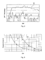
- Fig. 2 is a diagram of the typical temperature profile at the inlet of the DPF during a city trip 50 (transient driving) and during a ride with almost constant speed 52 (stationary driving) shown.
- At about constant speed is a stationary state and it can be a significant higher, typically around 50-100 ° C higher temperature in contrast be achieved for city driving, with the frequent temperature drops due to the Transient driving by thrust and idle occur.
- Fig. 3 is a diagram of the temperature profile over the regeneration time for a system with fuel additive 54 and a catalytically coated system 56 shown.
- a drop in the exhaust gas temperature leads to an extension of the required regeneration time, due to the exponential Dependence of the regeneration rate on the temperature.
- EP 1 281 852 relates to a method for the regeneration of a particulate filter after a main injection two post-injections are performed.
- the first post-injection in combination with the main injection causes a stable, late combustion to achieve a higher temperature of the exhaust gas.
- the second post-injection is carried out after the combustion process, so that the exhaust gases unburned hydrocarbons are supplied, which is a catalyst activate and improve its effectiveness.
- the DE 100 33 159 A1 relates to an internal combustion engine, in particular for a motor vehicle, with an exhaust gas line, in which a regenerable particle filter is arranged is.
- the internal combustion engine comprises a controller, the demand-dependent the Carrying out a regeneration of the particulate filter allows.
- a catalytic element e.g. an oxidation catalyst and a temperature sensor arranged.
- the temperature sensor is with the Connected control and determines a temperature feedback.
- a fuel injector is provided, which is the implementation of Nachspritzvor réellen allows.
- the controller for performing the regeneration of the particulate filter actuated the fuel injection device for performing the Nachspritzvor réelle.
- the Control performs a comparison of the actual temperature value with a predetermined Temperature setpoint and regulates the fuel injection device in dependence this comparison.
- the object of the present invention is therefore an apparatus and a method to propose for the regeneration of an exhaust aftertreatment device, which even at low engine loads can cause higher exhaust gas temperatures.
- An essential idea of the invention is to increase the temperature and / or hydrocarbon concentration of the exhaust gases by at least two post-injections of fuel in the working cycle of the internal combustion engine.
- the invention is particularly suitable for a diesel powered motor vehicle equipped with an exhaust aftertreatment device that periodically requires achieving an increased thermal level for DPF regeneration and / or desulfurization of a NO x storage catalyst.
- An engine management system of a motor vehicle should have the capability for several Have fuel injections, namely injections during the expansion stroke and after the main injection (post-injection). According to the invention are now in the labor or expansion stroke more (at least two) separate post-injections made after the main injection.
- the invention now relates to a method for the regeneration of an exhaust gas aftertreatment device in the exhaust system of an internal combustion engine, in particular a Particulate filter in the exhaust system of a diesel engine.
- an exhaust gas aftertreatment device in the exhaust system of an internal combustion engine, in particular a Particulate filter in the exhaust system of a diesel engine.
- the invention is or will be the temperature and / or hydrocarbon concentration of the exhaust gases at least two post-injections of fuel in the power stroke of the internal combustion engine elevated.
- the timing and the fuel amount of each of the at least two Nacheinspritzungen depending on ambient conditions of the internal combustion engine how ambient temperature and / or ambient air pressure are set.
- the timing and amount of fuel of each of the at least two post-injections can also depend on a deviation in the air path of the internal combustion engine Getting corrected.
- the invention it is possible to determine the time and the fuel quantity of each of the at least two post-injections depending on a temperature difference between a setpoint and a measuring temperature of the exhaust gases of the internal combustion engine regulate.
- the invention further relates to a device for the regeneration of an exhaust gas aftertreatment device in the exhaust system of an internal combustion engine, in particular a Particulate filter in the exhaust system of a diesel engine.
- the device is drawing itself by a control and regulating structure, which is designed such that the temperature and / or hydrocarbon concentration of the exhaust gases through at least two post-injections of fuel in the working cycle of the internal combustion engine is increased or become.
- control and regulating structure comprises a post-injection map, which is designed to be dependent on operating conditions of the internal combustion engine such as engine temperature, engine speed, torque, cooling water temperature and / or cylinder head temperature, the timing and fuel quantity of each of the to set at least two post-injections in steady-state operation.
- the Nacheinspritzsignale the stationary calibrated maps in the transient Operation can be used.
- control rule structure may include a correction map, the is designed to be dependent on ambient conditions of the internal combustion engine like ambient temperature and / or ambient air pressure the time and the Fuel quantity of each of the at least two post-injections in steady-state operation adjust.
- control and regulating structure comprises a Transient correction map designed to be dependent on transient operating conditions the internal combustion engine, the timing and the amount of fuel correct each of the at least two post-injections in transient operation.
- Transient operation will generally be the transition from one to the next Engine operating point (engine speed / engine torque) understood, but also For example, an operation with frequently and rapidly changing engine speed and a changing motor torque, such as in a transient Driving operation of a motor vehicle in city traffic occurs.
- the control structure may also include an air path correction map, which is designed to be dependent on a deviation in the air path of Internal combustion engine the timing and fuel quantity of each of the at least to correct two post-injections.
- a regulator unit configured to be dependent on a temperature difference between a desired and a measuring temperature of the exhaust gases of the internal combustion engine the time and amount of fuel of each of the at least two To regulate post-injections.
- control and regulating structure comprises a control limiter, which is designed to correct the timing and fuel quantity of each of the at least two post-injections depending on the temperature difference between the setpoint and the measuring temperature of the exhaust gases of the internal combustion engine such to limit that no critical exhaust gas temperatures are exceeded.
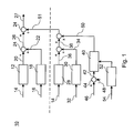
- control and regulating structure 10 for a diesel engine
- FIG. 10 An implementation of the multiple post-injection strategy of the invention in the form of a control and regulating structure 10 for a diesel engine is shown in FIG.
- the control and regulating structure 10 For example, in the form of software or electronic circuit as Be implemented as part of an engine management system.
- the illustrated block diagram the control structure 10 is corresponding to the number of used post-injections repeated; it is also time, i. the Start of injection and duration of injection, as well as the amount of post-injection applicable.
- the illustrated control structure 10 comprises three main elements:
- a post-injection map 12 becomes dependent on engine operating signals 14 (engine speed / motor torque) used.
- the post-injection signal is calibrated to the required regeneration temperature in steady-state operation, but also used uncorrected in transient operation.
- the stationary operation calibration for the time or amount of post-injection is due ambient conditions such as engine temperature (cooling water temperature, Cylinder head temperature) and ambient temperature and air pressure via a correction map 18 corrected.
- the correction map 18 receives an ambient signal 16.
- the post-injection map 12 generates a post-injection signal 20 and the correction map 18 is a correction signal 22. Both signals 20 and 22 become is summed by an adder 24 to a post-injection control signal 26, the determines the time and amount of post injections.
- the post-injection control signal 26 is controlled (by the elements 12, 18 and 24 above the dashed line).
- the structure explained above is for any one Number of separate post-injections applicable.
- the simple one discussed above includes Post-injection strategy further additional correction elements for a transient Driving.
- a correction signal 51 is generated, this in turn from a transient and Lucaspfadkorrektursignal 38 and a Regulator signal 50 is formed.
- the correction signal 51 is supplied with the post injection control signal 26 by means of an adder 24 to a corrected Nacheinspritzêtsignal 27 added. The generation of the correction signal 51 will now be described below explained.
- a transient correction map 28 is during transient driving conditions active and as shown in Fig. 1, a function of the engine operating condition, the is provided in the form of engine operating signals 14.
- transient Driving conditions has been shown that the temperature targets of the stationary Driving operation often can not be achieved. Instead, the exhaust gas temperature remains at a lower level, often 50 to 100 ° C lower than required.
- the boundary conditions mentioned above for a relatively short period of time, which is for stationary driving (such as the turbine inlet temperature, the minimum oxygen level, Etc.).
- This is achieved by generating a second steady state calibration with a modified target temperature (set to a higher level and modified boundary conditions (such as lower Oxygen levels), which is then used in a so-called heat-up mode is implemented by the transient correction map 28.
- An air path correction map 30 processes deviations 32 in the parameters of the airpath and generates an airpath correction signal 34 for intake manifold pressure, Mass air flow and / or the intake manifold temperature.
- the injection maps for stationary driving are usually for a certain target pressure optimized. During transient driving, deviations from required target pressure, so that the original Nacheinspritzparameter not is still optimal. Instead, a different post-injection time must be used and / or amount used to maintain the optimum exhaust gas temperature receive.
- This controller structure includes two elements:
- a temperature correction control unit 40 represents a control term that represents the Transient correction by means of a control signal 50 in response to a temperature difference signal 42 between a desired temperature in the form of a corresponding desired temperature signal 46 and a measuring temperature in the form of a temperature measuring signal 48 regulated.
- the temperature difference signal 42 is obtained by means of a subtractor 44 from the temperature command signal 46 and the temperature measurement signal 48th determined. No additional heating or transient corrections are necessary if the target temperature has already been reached, and the controller signal 50 would Assume zero value.
- a control limiter 52 is provided to ensure that the critical thermal limits of the various components are not exceeded. Therefore, a permissible maximum value for the feedback correction factor becomes one Function of the measured exhaust gas temperature in the form of an exhaust gas temperature measurement signal 54 beyond the critical limits (turbine inlet temperature, catalyst temperature, exothermic reaction in the catalyst, etc.).
- the maximal Limit of the controller signal 50 is set to zero when the measured temperatures reach their stationary driving limits (maximum catalyst outlet temperature typically around 650 ° C and a maximum turbine inlet temperature typically around 750 to 800 ° C).
Landscapes
- Engineering & Computer Science (AREA)
- Chemical & Material Sciences (AREA)
- Combustion & Propulsion (AREA)
- Mechanical Engineering (AREA)
- General Engineering & Computer Science (AREA)
- Exhaust Gas After Treatment (AREA)
- Electrical Control Of Air Or Fuel Supplied To Internal-Combustion Engine (AREA)
Priority Applications (1)
| Application Number | Priority Date | Filing Date | Title |
|---|---|---|---|
| EP05104883.3A EP1584809B1 (fr) | 2003-11-19 | 2003-11-19 | Procédé pour la régénération d'un équipement de post traitement des gaz d'échappement |
Applications Claiming Priority (2)
| Application Number | Priority Date | Filing Date | Title |
|---|---|---|---|
| EP05104883.3A EP1584809B1 (fr) | 2003-11-19 | 2003-11-19 | Procédé pour la régénération d'un équipement de post traitement des gaz d'échappement |
| EP03104278A EP1533500B1 (fr) | 2003-11-19 | 2003-11-19 | Procédé et dispositif pour régénération d'un équipement de post traitement des gaz d'échappement |
Related Parent Applications (2)
| Application Number | Title | Priority Date | Filing Date |
|---|---|---|---|
| EP03104278.1 Division | 2003-11-19 | ||
| EP03104278A Division EP1533500B1 (fr) | 2003-11-19 | 2003-11-19 | Procédé et dispositif pour régénération d'un équipement de post traitement des gaz d'échappement |
Publications (2)
| Publication Number | Publication Date |
|---|---|
| EP1584809A1 true EP1584809A1 (fr) | 2005-10-12 |
| EP1584809B1 EP1584809B1 (fr) | 2018-10-17 |
Family
ID=34429510
Family Applications (2)
| Application Number | Title | Priority Date | Filing Date |
|---|---|---|---|
| EP03104278A Expired - Lifetime EP1533500B1 (fr) | 2003-11-19 | 2003-11-19 | Procédé et dispositif pour régénération d'un équipement de post traitement des gaz d'échappement |
| EP05104883.3A Expired - Lifetime EP1584809B1 (fr) | 2003-11-19 | 2003-11-19 | Procédé pour la régénération d'un équipement de post traitement des gaz d'échappement |
Family Applications Before (1)
| Application Number | Title | Priority Date | Filing Date |
|---|---|---|---|
| EP03104278A Expired - Lifetime EP1533500B1 (fr) | 2003-11-19 | 2003-11-19 | Procédé et dispositif pour régénération d'un équipement de post traitement des gaz d'échappement |
Country Status (2)
| Country | Link |
|---|---|
| EP (2) | EP1533500B1 (fr) |
| DE (1) | DE50309107D1 (fr) |
Cited By (3)
| Publication number | Priority date | Publication date | Assignee | Title |
|---|---|---|---|---|
| EP1965059A1 (fr) * | 2007-02-28 | 2008-09-03 | HONDA MOTOR CO., Ltd. | Contrôle de post-injection de carburant d'un moteur à combustion interne |
| CN104819042A (zh) * | 2014-02-05 | 2015-08-05 | 大众汽车有限公司 | 内燃机颗粒过滤器的再生方法及相应的控制器和交通工具 |
| EP3112642A4 (fr) * | 2014-02-26 | 2017-11-08 | Yanmar Co., Ltd. | Moteur |
Families Citing this family (8)
| Publication number | Priority date | Publication date | Assignee | Title |
|---|---|---|---|---|
| JP4301070B2 (ja) * | 2004-04-30 | 2009-07-22 | 株式会社デンソー | 内燃機関の排気浄化装置 |
| US8261535B2 (en) | 2005-06-30 | 2012-09-11 | GM Global Technology Operations LLC | Enhanced post injection control system for diesel particulate filters |
| JP3933172B2 (ja) * | 2005-07-15 | 2007-06-20 | いすゞ自動車株式会社 | 排気ガス浄化システムの制御方法及び排気ガス浄化システム |
| US8479495B2 (en) | 2009-03-03 | 2013-07-09 | GM Global Technology Operations LLC | Environmental factor based particulate filter regeneration |
| US9574483B2 (en) | 2010-01-14 | 2017-02-21 | GM Global Technology Operations LLC | System and method for controlling exhaust gas temperature during particulate matter filter regeneration |
| DE102018214856A1 (de) * | 2018-08-31 | 2020-03-05 | Robert Bosch Gmbh | Verfahren und Computerprogrammprodukt zum Betrieb einer Brennkraftmaschine mit unterschiedlichen Kraftstoffen |
| CN113614351B (zh) * | 2019-03-20 | 2023-12-01 | 沃尔沃遍达公司 | 用于控制内燃机的方法和控制系统 |
| CN115045774B (zh) * | 2021-11-19 | 2025-02-18 | 长城汽车股份有限公司 | 一种lnt的脱硫的方法、系统、电子设备和介质 |
Citations (6)
| Publication number | Priority date | Publication date | Assignee | Title |
|---|---|---|---|---|
| US5479775A (en) * | 1993-04-23 | 1996-01-02 | Mercedes-Benz Ag | Air-compressing fuel-injection internal-combustion engine with an exhaust treatment device for reduction of nitrogen oxides |
| EP1148227A2 (fr) * | 2000-04-18 | 2001-10-24 | Toyota Jidosha Kabushiki Kaisha | Dispositif de purification de gaz d'échappement |
| DE10033158C1 (de) * | 2000-07-07 | 2001-12-20 | Daimler Chrysler Ag | Brennkraftmaschine, insbesondere für Kraftfahrzeuge |
| DE10033159A1 (de) * | 2000-07-07 | 2002-01-17 | Daimler Chrysler Ag | Brennkraftmaschine, insbesondere für Kraftfahrzeuge |
| US20020194837A1 (en) * | 2001-06-26 | 2002-12-26 | Caterpillar Inc. | Post injections during cold operation |
| EP1281852A2 (fr) * | 2001-08-03 | 2003-02-05 | C.R.F. Società Consortile per Azioni | Méthode pour lancer la régénération d'un filtre à particules pour un moteur diesel à injection directe avec système d'injection à common-rail |
Family Cites Families (4)
| Publication number | Priority date | Publication date | Assignee | Title |
|---|---|---|---|---|
| CN1077212C (zh) * | 1996-07-02 | 2002-01-02 | 三菱自动车工业株式会社 | 缸内喷射内燃机用废气加热系统 |
| JP4505702B2 (ja) * | 2000-12-01 | 2010-07-21 | マツダ株式会社 | ディーゼルエンジンの燃料噴射制御装置 |
| DE60212079T2 (de) * | 2001-02-20 | 2006-12-07 | Isuzu Motors Ltd. | Verfahren zur Steuerung der Kraftstoffeinspritzung für Dieselmotoren und Regenerationssteuerungsverfahren für Abgasnachbehandlungsvorrichtung |
| DE50110758D1 (de) * | 2001-09-25 | 2006-09-28 | Ford Global Tech Llc | Vorrichtung und Verfahren zur Regeneration einer Abgasbehandlungseinrichtung |
-
2003
- 2003-11-19 EP EP03104278A patent/EP1533500B1/fr not_active Expired - Lifetime
- 2003-11-19 DE DE50309107T patent/DE50309107D1/de not_active Expired - Lifetime
- 2003-11-19 EP EP05104883.3A patent/EP1584809B1/fr not_active Expired - Lifetime
Patent Citations (6)
| Publication number | Priority date | Publication date | Assignee | Title |
|---|---|---|---|---|
| US5479775A (en) * | 1993-04-23 | 1996-01-02 | Mercedes-Benz Ag | Air-compressing fuel-injection internal-combustion engine with an exhaust treatment device for reduction of nitrogen oxides |
| EP1148227A2 (fr) * | 2000-04-18 | 2001-10-24 | Toyota Jidosha Kabushiki Kaisha | Dispositif de purification de gaz d'échappement |
| DE10033158C1 (de) * | 2000-07-07 | 2001-12-20 | Daimler Chrysler Ag | Brennkraftmaschine, insbesondere für Kraftfahrzeuge |
| DE10033159A1 (de) * | 2000-07-07 | 2002-01-17 | Daimler Chrysler Ag | Brennkraftmaschine, insbesondere für Kraftfahrzeuge |
| US20020194837A1 (en) * | 2001-06-26 | 2002-12-26 | Caterpillar Inc. | Post injections during cold operation |
| EP1281852A2 (fr) * | 2001-08-03 | 2003-02-05 | C.R.F. Società Consortile per Azioni | Méthode pour lancer la régénération d'un filtre à particules pour un moteur diesel à injection directe avec système d'injection à common-rail |
Cited By (6)
| Publication number | Priority date | Publication date | Assignee | Title |
|---|---|---|---|---|
| EP1965059A1 (fr) * | 2007-02-28 | 2008-09-03 | HONDA MOTOR CO., Ltd. | Contrôle de post-injection de carburant d'un moteur à combustion interne |
| CN104819042A (zh) * | 2014-02-05 | 2015-08-05 | 大众汽车有限公司 | 内燃机颗粒过滤器的再生方法及相应的控制器和交通工具 |
| EP2910757A1 (fr) * | 2014-02-05 | 2015-08-26 | Volkswagen Aktiengesellschaft | Procédé de régénération d'un filtre à particules d'un moteur à combustion interne et moyen de commande en étant équipé et véhicule |
| CN104819042B (zh) * | 2014-02-05 | 2018-11-27 | 大众汽车有限公司 | 内燃机颗粒过滤器的再生方法及相应的控制器和交通工具 |
| EP3112642A4 (fr) * | 2014-02-26 | 2017-11-08 | Yanmar Co., Ltd. | Moteur |
| US10502156B2 (en) | 2014-02-26 | 2019-12-10 | Yanmar Co., Ltd. | Engine controller based on atmospheric pressure |
Also Published As
| Publication number | Publication date |
|---|---|
| DE50309107D1 (de) | 2008-03-20 |
| EP1584809B1 (fr) | 2018-10-17 |
| EP1533500B1 (fr) | 2008-01-30 |
| EP1533500A1 (fr) | 2005-05-25 |
Similar Documents
| Publication | Publication Date | Title |
|---|---|---|
| DE60221913T2 (de) | Kraftstoffinjektionssteuerverfahren für einen Dieselmotor und regeneratives Steuerverfahren für Abgasnach behandlungseinrichtung | |
| EP1121513B1 (fr) | Procede de reduction des oxydes d'azote dans les gaz d'echappement d'un moteur a combustion interne fonctionnant avec un melange pauvre | |
| DE10038655B4 (de) | Luftkraftstoffverhältnisregelgerät für Brennkraftmaschinen | |
| DE10325083B4 (de) | Kraftstoffeinspritzsteuersystem für eine Brennkraftmaschine | |
| DE60021447T2 (de) | Brennkraftmaschine mit Direkteinspritzung | |
| EP1161618B1 (fr) | Procede de desulfatage d'un catalyseur accumulateur de nox | |
| DE102016207667B4 (de) | Verfahren und Vorrichtung zur Regeneration eines Partikelfilters bei einem Kraftfahrzeug mit Hybridantrieb | |
| DE102010017575B4 (de) | Verfahren zum Betreiben einer fremdgezündeten Brennkraftmaschine und Brennkraftmaschine zur Durchführung eines derartigen Verfahrens | |
| WO2000023702A1 (fr) | PROCEDE ET DISPOSITIF DE DESULFURATION D'UN CATALYSEUR A ACCUMULATION DE NO¿x? | |
| DE112013003053T5 (de) | Filterregeneration unter Verwendung von Filtertemperatur-Modulation | |
| EP1533500B1 (fr) | Procédé et dispositif pour régénération d'un équipement de post traitement des gaz d'échappement | |
| DE102011105601B4 (de) | Steuersystem zur Regeneration eines Partikelmaterialfilters unter Verwendung eines katalytischen Wandlers als einer Verbrennungseinrichtung | |
| DE102017006514B4 (de) | Abgasemissions-Regel bzw. - Steuersystem, Verfahren zum Regeln bzw. Steuern eines Abgassystems und Computerprogrammprodukt | |
| DE10339005A1 (de) | Abgasreinigungsverfahren für Verbrennungsmtoor | |
| DE102015209979B4 (de) | Verfahren zum Bestimmen eines Hybridantrieb-Drehmomentschwellwertes, zum Betrieb einer Hybridantriebsvorrichtung und Hybridfahrzeug | |
| DE102018005836B4 (de) | Steuersystem für einen Motor, Motor, Steuerverfahren und Computerprogrammprodukt | |
| DE10158740B4 (de) | Verfahren und Anordnung zur Erzeugung zusätzlicher Motorlasten beim Start | |
| DE202015000385U1 (de) | Kraftfahrzeug | |
| DE102014016700A1 (de) | Verfahren zur Regeneration eines ottomotorischen Partikelfilters | |
| DE112018002095T5 (de) | Abgasbehandlungsvorrichtung für Verbrennungskraftmaschine | |
| DE102005003880B4 (de) | Verfahren zur Steuerung einer Kraftstoffdirekteinspritzung und Kraftfahrzeug | |
| DE10222769A1 (de) | Verfahren und Vorrichtung zur Steuerung eines Motorstartvorgangs | |
| WO2006072499A2 (fr) | Procede pour reduire les emissions d'un vehicule automobile en influant sur la puissance de l'alternateur | |
| DE102012022156B4 (de) | Verfahren zur Kraftstoffeinspritzung in einen Dieselmotor sowie Steuereinrichtung | |
| DE102009045088B4 (de) | Verfahren zur Steuerung eines Verbrennungsmotors in Verbindung mit einer exothermen Regeneration einer Abgasnachbehandlungkomponente |
Legal Events
| Date | Code | Title | Description |
|---|---|---|---|
| PUAI | Public reference made under article 153(3) epc to a published international application that has entered the european phase |
Free format text: ORIGINAL CODE: 0009012 |
|
| AC | Divisional application: reference to earlier application |
Ref document number: 1533500 Country of ref document: EP Kind code of ref document: P |
|
| AK | Designated contracting states |
Kind code of ref document: A1 Designated state(s): AT BE BG CH CY CZ DE DK EE ES FI FR GB GR HU IE IT LI LU MC NL PT RO SE SI SK TR |
|
| AX | Request for extension of the european patent |
Extension state: AL LT LV MK |
|
| RIN1 | Information on inventor provided before grant (corrected) |
Inventor name: YACOUB, YASSER MOHAMMED SAYED Inventor name: KUENSTLER, JOHANNES Inventor name: MORAAL, PAUL EDUARD |
|
| RAP1 | Party data changed (applicant data changed or rights of an application transferred) |
Owner name: FORD GLOBAL TECHNOLOGIES, LLC. |
|
| 17P | Request for examination filed |
Effective date: 20060412 |
|
| AKX | Designation fees paid |
Designated state(s): DE FR GB |
|
| 17Q | First examination report despatched |
Effective date: 20070724 |
|
| RIC1 | Information provided on ipc code assigned before grant |
Ipc: F02D 41/40 19850101ALI20180525BHEP Ipc: F02D 41/10 19850101ALN20180525BHEP Ipc: F02D 41/18 19850101ALN20180525BHEP Ipc: F02D 41/02 19850101AFI20180525BHEP Ipc: F02D 41/14 19850101ALN20180525BHEP |
|
| GRAP | Despatch of communication of intention to grant a patent |
Free format text: ORIGINAL CODE: EPIDOSNIGR1 |
|
| INTG | Intention to grant announced |
Effective date: 20180719 |
|
| GRAS | Grant fee paid |
Free format text: ORIGINAL CODE: EPIDOSNIGR3 |
|
| GRAA | (expected) grant |
Free format text: ORIGINAL CODE: 0009210 |
|
| AC | Divisional application: reference to earlier application |
Ref document number: 1533500 Country of ref document: EP Kind code of ref document: P |
|
| AK | Designated contracting states |
Kind code of ref document: B1 Designated state(s): DE FR GB |
|
| REG | Reference to a national code |
Ref country code: GB Ref legal event code: FG4D Free format text: NOT ENGLISH |
|
| REG | Reference to a national code |
Ref country code: DE Ref legal event code: R096 Ref document number: 50315794 Country of ref document: DE |
|
| REG | Reference to a national code |
Ref country code: DE Ref legal event code: R097 Ref document number: 50315794 Country of ref document: DE |
|
| PLBE | No opposition filed within time limit |
Free format text: ORIGINAL CODE: 0009261 |
|
| STAA | Information on the status of an ep patent application or granted ep patent |
Free format text: STATUS: NO OPPOSITION FILED WITHIN TIME LIMIT |
|
| 26N | No opposition filed |
Effective date: 20190718 |
|
| PGFP | Annual fee paid to national office [announced via postgrant information from national office to epo] |
Ref country code: FR Payment date: 20191029 Year of fee payment: 17 |
|
| PGFP | Annual fee paid to national office [announced via postgrant information from national office to epo] |
Ref country code: GB Payment date: 20191029 Year of fee payment: 17 |
|
| GBPC | Gb: european patent ceased through non-payment of renewal fee |
Effective date: 20201119 |
|
| PG25 | Lapsed in a contracting state [announced via postgrant information from national office to epo] |
Ref country code: FR Free format text: LAPSE BECAUSE OF NON-PAYMENT OF DUE FEES Effective date: 20201130 |
|
| PG25 | Lapsed in a contracting state [announced via postgrant information from national office to epo] |
Ref country code: GB Free format text: LAPSE BECAUSE OF NON-PAYMENT OF DUE FEES Effective date: 20201119 |
|
| PGFP | Annual fee paid to national office [announced via postgrant information from national office to epo] |
Ref country code: DE Payment date: 20220615 Year of fee payment: 20 |
|
| P01 | Opt-out of the competence of the unified patent court (upc) registered |
Effective date: 20230620 |
|
| REG | Reference to a national code |
Ref country code: DE Ref legal event code: R071 Ref document number: 50315794 Country of ref document: DE |