EP1584809A1 - Method and apparatus for regeneration of an exhaust gas after-treatment device - Google Patents
Method and apparatus for regeneration of an exhaust gas after-treatment device Download PDFInfo
- Publication number
- EP1584809A1 EP1584809A1 EP05104883A EP05104883A EP1584809A1 EP 1584809 A1 EP1584809 A1 EP 1584809A1 EP 05104883 A EP05104883 A EP 05104883A EP 05104883 A EP05104883 A EP 05104883A EP 1584809 A1 EP1584809 A1 EP 1584809A1
- Authority
- EP
- European Patent Office
- Prior art keywords
- temperature
- post
- injection
- internal combustion
- combustion engine
- Prior art date
- Legal status (The legal status is an assumption and is not a legal conclusion. Google has not performed a legal analysis and makes no representation as to the accuracy of the status listed.)
- Granted
Links
- 230000008929 regeneration Effects 0.000 title claims abstract description 23
- 238000011069 regeneration method Methods 0.000 title claims abstract description 23
- 238000000034 method Methods 0.000 title claims abstract description 11
- 238000002347 injection Methods 0.000 claims abstract description 113
- 239000007924 injection Substances 0.000 claims abstract description 113
- 239000000446 fuel Substances 0.000 claims abstract description 33
- 239000007789 gas Substances 0.000 claims description 56
- 238000002485 combustion reaction Methods 0.000 claims description 39
- 238000012937 correction Methods 0.000 claims description 34
- 229930195733 hydrocarbon Natural products 0.000 claims description 18
- 150000002430 hydrocarbons Chemical class 0.000 claims description 18
- 229910052760 oxygen Inorganic materials 0.000 claims description 14
- 239000001301 oxygen Substances 0.000 claims description 14
- QVGXLLKOCUKJST-UHFFFAOYSA-N atomic oxygen Chemical compound [O] QVGXLLKOCUKJST-UHFFFAOYSA-N 0.000 claims description 11
- 239000002245 particle Substances 0.000 claims description 11
- 230000001105 regulatory effect Effects 0.000 claims description 10
- 239000004215 Carbon black (E152) Substances 0.000 claims description 6
- 238000005259 measurement Methods 0.000 claims 1
- 230000001172 regenerating effect Effects 0.000 claims 1
- 230000001419 dependent effect Effects 0.000 abstract description 9
- 230000008569 process Effects 0.000 abstract description 2
- 230000001052 transient effect Effects 0.000 description 29
- 239000003054 catalyst Substances 0.000 description 15
- 239000003570 air Substances 0.000 description 12
- 239000002816 fuel additive Substances 0.000 description 8
- 238000010586 diagram Methods 0.000 description 6
- 206010053615 Thermal burn Diseases 0.000 description 5
- 238000009529 body temperature measurement Methods 0.000 description 4
- 238000006243 chemical reaction Methods 0.000 description 4
- 238000010438 heat treatment Methods 0.000 description 4
- MYMOFIZGZYHOMD-UHFFFAOYSA-N Dioxygen Chemical compound O=O MYMOFIZGZYHOMD-UHFFFAOYSA-N 0.000 description 3
- 239000000498 cooling water Substances 0.000 description 3
- 230000003647 oxidation Effects 0.000 description 3
- 238000007254 oxidation reaction Methods 0.000 description 3
- 239000004071 soot Substances 0.000 description 3
- OKTJSMMVPCPJKN-UHFFFAOYSA-N Carbon Chemical compound [C] OKTJSMMVPCPJKN-UHFFFAOYSA-N 0.000 description 2
- 239000012080 ambient air Substances 0.000 description 2
- 229910052799 carbon Inorganic materials 0.000 description 2
- 230000003197 catalytic effect Effects 0.000 description 2
- 230000007613 environmental effect Effects 0.000 description 2
- 230000007935 neutral effect Effects 0.000 description 2
- 230000000638 stimulation Effects 0.000 description 2
- 238000011144 upstream manufacturing Methods 0.000 description 2
- 238000013459 approach Methods 0.000 description 1
- 230000015572 biosynthetic process Effects 0.000 description 1
- 230000008859 change Effects 0.000 description 1
- 238000006477 desulfuration reaction Methods 0.000 description 1
- 230000023556 desulfurization Effects 0.000 description 1
- 238000011161 development Methods 0.000 description 1
- 230000018109 developmental process Effects 0.000 description 1
- 238000010790 dilution Methods 0.000 description 1
- 239000012895 dilution Substances 0.000 description 1
- 238000001914 filtration Methods 0.000 description 1
- 239000000295 fuel oil Substances 0.000 description 1
- 238000004519 manufacturing process Methods 0.000 description 1
- 239000000203 mixture Substances 0.000 description 1
- 238000002360 preparation method Methods 0.000 description 1
- 230000004044 response Effects 0.000 description 1
- 230000035945 sensitivity Effects 0.000 description 1
- 238000003860 storage Methods 0.000 description 1
- 230000007704 transition Effects 0.000 description 1
Images
Classifications
-
- F—MECHANICAL ENGINEERING; LIGHTING; HEATING; WEAPONS; BLASTING
- F02—COMBUSTION ENGINES; HOT-GAS OR COMBUSTION-PRODUCT ENGINE PLANTS
- F02D—CONTROLLING COMBUSTION ENGINES
- F02D41/00—Electrical control of supply of combustible mixture or its constituents
- F02D41/30—Controlling fuel injection
- F02D41/38—Controlling fuel injection of the high pressure type
- F02D41/40—Controlling fuel injection of the high pressure type with means for controlling injection timing or duration
- F02D41/402—Multiple injections
- F02D41/405—Multiple injections with post injections
-
- F—MECHANICAL ENGINEERING; LIGHTING; HEATING; WEAPONS; BLASTING
- F02—COMBUSTION ENGINES; HOT-GAS OR COMBUSTION-PRODUCT ENGINE PLANTS
- F02D—CONTROLLING COMBUSTION ENGINES
- F02D41/00—Electrical control of supply of combustible mixture or its constituents
- F02D41/02—Circuit arrangements for generating control signals
- F02D41/021—Introducing corrections for particular conditions exterior to the engine
- F02D41/0235—Introducing corrections for particular conditions exterior to the engine in relation with the state of the exhaust gas treating apparatus
- F02D41/027—Introducing corrections for particular conditions exterior to the engine in relation with the state of the exhaust gas treating apparatus to purge or regenerate the exhaust gas treating apparatus
- F02D41/029—Introducing corrections for particular conditions exterior to the engine in relation with the state of the exhaust gas treating apparatus to purge or regenerate the exhaust gas treating apparatus the exhaust gas treating apparatus being a particulate filter
-
- F—MECHANICAL ENGINEERING; LIGHTING; HEATING; WEAPONS; BLASTING
- F02—COMBUSTION ENGINES; HOT-GAS OR COMBUSTION-PRODUCT ENGINE PLANTS
- F02D—CONTROLLING COMBUSTION ENGINES
- F02D41/00—Electrical control of supply of combustible mixture or its constituents
- F02D41/30—Controlling fuel injection
- F02D41/38—Controlling fuel injection of the high pressure type
- F02D2041/389—Controlling fuel injection of the high pressure type for injecting directly into the cylinder
-
- F—MECHANICAL ENGINEERING; LIGHTING; HEATING; WEAPONS; BLASTING
- F02—COMBUSTION ENGINES; HOT-GAS OR COMBUSTION-PRODUCT ENGINE PLANTS
- F02D—CONTROLLING COMBUSTION ENGINES
- F02D2200/00—Input parameters for engine control
- F02D2200/02—Input parameters for engine control the parameters being related to the engine
- F02D2200/04—Engine intake system parameters
- F02D2200/0406—Intake manifold pressure
-
- F—MECHANICAL ENGINEERING; LIGHTING; HEATING; WEAPONS; BLASTING
- F02—COMBUSTION ENGINES; HOT-GAS OR COMBUSTION-PRODUCT ENGINE PLANTS
- F02D—CONTROLLING COMBUSTION ENGINES
- F02D2200/00—Input parameters for engine control
- F02D2200/02—Input parameters for engine control the parameters being related to the engine
- F02D2200/04—Engine intake system parameters
- F02D2200/0414—Air temperature
-
- F—MECHANICAL ENGINEERING; LIGHTING; HEATING; WEAPONS; BLASTING
- F02—COMBUSTION ENGINES; HOT-GAS OR COMBUSTION-PRODUCT ENGINE PLANTS
- F02D—CONTROLLING COMBUSTION ENGINES
- F02D2200/00—Input parameters for engine control
- F02D2200/70—Input parameters for engine control said parameters being related to the vehicle exterior
- F02D2200/703—Atmospheric pressure
-
- F—MECHANICAL ENGINEERING; LIGHTING; HEATING; WEAPONS; BLASTING
- F02—COMBUSTION ENGINES; HOT-GAS OR COMBUSTION-PRODUCT ENGINE PLANTS
- F02D—CONTROLLING COMBUSTION ENGINES
- F02D41/00—Electrical control of supply of combustible mixture or its constituents
- F02D41/02—Circuit arrangements for generating control signals
- F02D41/021—Introducing corrections for particular conditions exterior to the engine
- F02D41/0235—Introducing corrections for particular conditions exterior to the engine in relation with the state of the exhaust gas treating apparatus
- F02D41/024—Introducing corrections for particular conditions exterior to the engine in relation with the state of the exhaust gas treating apparatus to increase temperature of the exhaust gas treating apparatus
- F02D41/0245—Introducing corrections for particular conditions exterior to the engine in relation with the state of the exhaust gas treating apparatus to increase temperature of the exhaust gas treating apparatus by increasing temperature of the exhaust gas leaving the engine
-
- F—MECHANICAL ENGINEERING; LIGHTING; HEATING; WEAPONS; BLASTING
- F02—COMBUSTION ENGINES; HOT-GAS OR COMBUSTION-PRODUCT ENGINE PLANTS
- F02D—CONTROLLING COMBUSTION ENGINES
- F02D41/00—Electrical control of supply of combustible mixture or its constituents
- F02D41/02—Circuit arrangements for generating control signals
- F02D41/021—Introducing corrections for particular conditions exterior to the engine
- F02D41/0235—Introducing corrections for particular conditions exterior to the engine in relation with the state of the exhaust gas treating apparatus
- F02D41/024—Introducing corrections for particular conditions exterior to the engine in relation with the state of the exhaust gas treating apparatus to increase temperature of the exhaust gas treating apparatus
- F02D41/025—Introducing corrections for particular conditions exterior to the engine in relation with the state of the exhaust gas treating apparatus to increase temperature of the exhaust gas treating apparatus by changing the composition of the exhaust gas, e.g. for exothermic reaction on exhaust gas treating apparatus
-
- F—MECHANICAL ENGINEERING; LIGHTING; HEATING; WEAPONS; BLASTING
- F02—COMBUSTION ENGINES; HOT-GAS OR COMBUSTION-PRODUCT ENGINE PLANTS
- F02D—CONTROLLING COMBUSTION ENGINES
- F02D41/00—Electrical control of supply of combustible mixture or its constituents
- F02D41/02—Circuit arrangements for generating control signals
- F02D41/04—Introducing corrections for particular operating conditions
- F02D41/10—Introducing corrections for particular operating conditions for acceleration
- F02D41/107—Introducing corrections for particular operating conditions for acceleration and deceleration
-
- F—MECHANICAL ENGINEERING; LIGHTING; HEATING; WEAPONS; BLASTING
- F02—COMBUSTION ENGINES; HOT-GAS OR COMBUSTION-PRODUCT ENGINE PLANTS
- F02D—CONTROLLING COMBUSTION ENGINES
- F02D41/00—Electrical control of supply of combustible mixture or its constituents
- F02D41/02—Circuit arrangements for generating control signals
- F02D41/14—Introducing closed-loop corrections
- F02D41/1438—Introducing closed-loop corrections using means for determining characteristics of the combustion gases; Sensors therefor
- F02D41/1444—Introducing closed-loop corrections using means for determining characteristics of the combustion gases; Sensors therefor characterised by the characteristics of the combustion gases
- F02D41/1446—Introducing closed-loop corrections using means for determining characteristics of the combustion gases; Sensors therefor characterised by the characteristics of the combustion gases the characteristics being exhaust temperatures
-
- F—MECHANICAL ENGINEERING; LIGHTING; HEATING; WEAPONS; BLASTING
- F02—COMBUSTION ENGINES; HOT-GAS OR COMBUSTION-PRODUCT ENGINE PLANTS
- F02D—CONTROLLING COMBUSTION ENGINES
- F02D41/00—Electrical control of supply of combustible mixture or its constituents
- F02D41/02—Circuit arrangements for generating control signals
- F02D41/18—Circuit arrangements for generating control signals by measuring intake air flow
- F02D41/187—Circuit arrangements for generating control signals by measuring intake air flow using a hot wire flow sensor
-
- Y—GENERAL TAGGING OF NEW TECHNOLOGICAL DEVELOPMENTS; GENERAL TAGGING OF CROSS-SECTIONAL TECHNOLOGIES SPANNING OVER SEVERAL SECTIONS OF THE IPC; TECHNICAL SUBJECTS COVERED BY FORMER USPC CROSS-REFERENCE ART COLLECTIONS [XRACs] AND DIGESTS
- Y02—TECHNOLOGIES OR APPLICATIONS FOR MITIGATION OR ADAPTATION AGAINST CLIMATE CHANGE
- Y02T—CLIMATE CHANGE MITIGATION TECHNOLOGIES RELATED TO TRANSPORTATION
- Y02T10/00—Road transport of goods or passengers
- Y02T10/10—Internal combustion engine [ICE] based vehicles
- Y02T10/40—Engine management systems
Definitions
- the invention relates to a method for the regeneration of an exhaust gas aftertreatment device according to the preamble of claim 1 and a corresponding device according to the preamble of claim 3.
- DPF diesel particulate filters
- short particle filters which collect the soot from a Diesel engine is ejected.
- the sensitivity of the combustion of the post-injection with respect to the injection time is critical especially at low engine loads.
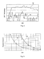
- Fig. 2 is a diagram of the typical temperature profile at the inlet of the DPF during a city trip 50 (transient driving) and during a ride with almost constant speed 52 (stationary driving) shown.
- At about constant speed is a stationary state and it can be a significant higher, typically around 50-100 ° C higher temperature in contrast be achieved for city driving, with the frequent temperature drops due to the Transient driving by thrust and idle occur.
- Fig. 3 is a diagram of the temperature profile over the regeneration time for a system with fuel additive 54 and a catalytically coated system 56 shown.
- a drop in the exhaust gas temperature leads to an extension of the required regeneration time, due to the exponential Dependence of the regeneration rate on the temperature.
- EP 1 281 852 relates to a method for the regeneration of a particulate filter after a main injection two post-injections are performed.
- the first post-injection in combination with the main injection causes a stable, late combustion to achieve a higher temperature of the exhaust gas.
- the second post-injection is carried out after the combustion process, so that the exhaust gases unburned hydrocarbons are supplied, which is a catalyst activate and improve its effectiveness.
- the DE 100 33 159 A1 relates to an internal combustion engine, in particular for a motor vehicle, with an exhaust gas line, in which a regenerable particle filter is arranged is.
- the internal combustion engine comprises a controller, the demand-dependent the Carrying out a regeneration of the particulate filter allows.
- a catalytic element e.g. an oxidation catalyst and a temperature sensor arranged.
- the temperature sensor is with the Connected control and determines a temperature feedback.
- a fuel injector is provided, which is the implementation of Nachspritzvor réellen allows.
- the controller for performing the regeneration of the particulate filter actuated the fuel injection device for performing the Nachspritzvor réelle.
- the Control performs a comparison of the actual temperature value with a predetermined Temperature setpoint and regulates the fuel injection device in dependence this comparison.
- the object of the present invention is therefore an apparatus and a method to propose for the regeneration of an exhaust aftertreatment device, which even at low engine loads can cause higher exhaust gas temperatures.
- An essential idea of the invention is to increase the temperature and / or hydrocarbon concentration of the exhaust gases by at least two post-injections of fuel in the working cycle of the internal combustion engine.
- the invention is particularly suitable for a diesel powered motor vehicle equipped with an exhaust aftertreatment device that periodically requires achieving an increased thermal level for DPF regeneration and / or desulfurization of a NO x storage catalyst.
- An engine management system of a motor vehicle should have the capability for several Have fuel injections, namely injections during the expansion stroke and after the main injection (post-injection). According to the invention are now in the labor or expansion stroke more (at least two) separate post-injections made after the main injection.
- the invention now relates to a method for the regeneration of an exhaust gas aftertreatment device in the exhaust system of an internal combustion engine, in particular a Particulate filter in the exhaust system of a diesel engine.
- an exhaust gas aftertreatment device in the exhaust system of an internal combustion engine, in particular a Particulate filter in the exhaust system of a diesel engine.
- the invention is or will be the temperature and / or hydrocarbon concentration of the exhaust gases at least two post-injections of fuel in the power stroke of the internal combustion engine elevated.
- the timing and the fuel amount of each of the at least two Nacheinspritzungen depending on ambient conditions of the internal combustion engine how ambient temperature and / or ambient air pressure are set.
- the timing and amount of fuel of each of the at least two post-injections can also depend on a deviation in the air path of the internal combustion engine Getting corrected.
- the invention it is possible to determine the time and the fuel quantity of each of the at least two post-injections depending on a temperature difference between a setpoint and a measuring temperature of the exhaust gases of the internal combustion engine regulate.
- the invention further relates to a device for the regeneration of an exhaust gas aftertreatment device in the exhaust system of an internal combustion engine, in particular a Particulate filter in the exhaust system of a diesel engine.
- the device is drawing itself by a control and regulating structure, which is designed such that the temperature and / or hydrocarbon concentration of the exhaust gases through at least two post-injections of fuel in the working cycle of the internal combustion engine is increased or become.
- control and regulating structure comprises a post-injection map, which is designed to be dependent on operating conditions of the internal combustion engine such as engine temperature, engine speed, torque, cooling water temperature and / or cylinder head temperature, the timing and fuel quantity of each of the to set at least two post-injections in steady-state operation.
- the Nacheinspritzsignale the stationary calibrated maps in the transient Operation can be used.
- control rule structure may include a correction map, the is designed to be dependent on ambient conditions of the internal combustion engine like ambient temperature and / or ambient air pressure the time and the Fuel quantity of each of the at least two post-injections in steady-state operation adjust.
- control and regulating structure comprises a Transient correction map designed to be dependent on transient operating conditions the internal combustion engine, the timing and the amount of fuel correct each of the at least two post-injections in transient operation.
- Transient operation will generally be the transition from one to the next Engine operating point (engine speed / engine torque) understood, but also For example, an operation with frequently and rapidly changing engine speed and a changing motor torque, such as in a transient Driving operation of a motor vehicle in city traffic occurs.
- the control structure may also include an air path correction map, which is designed to be dependent on a deviation in the air path of Internal combustion engine the timing and fuel quantity of each of the at least to correct two post-injections.
- a regulator unit configured to be dependent on a temperature difference between a desired and a measuring temperature of the exhaust gases of the internal combustion engine the time and amount of fuel of each of the at least two To regulate post-injections.
- control and regulating structure comprises a control limiter, which is designed to correct the timing and fuel quantity of each of the at least two post-injections depending on the temperature difference between the setpoint and the measuring temperature of the exhaust gases of the internal combustion engine such to limit that no critical exhaust gas temperatures are exceeded.
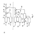
- control and regulating structure 10 for a diesel engine
- FIG. 10 An implementation of the multiple post-injection strategy of the invention in the form of a control and regulating structure 10 for a diesel engine is shown in FIG.
- the control and regulating structure 10 For example, in the form of software or electronic circuit as Be implemented as part of an engine management system.
- the illustrated block diagram the control structure 10 is corresponding to the number of used post-injections repeated; it is also time, i. the Start of injection and duration of injection, as well as the amount of post-injection applicable.
- the illustrated control structure 10 comprises three main elements:
- a post-injection map 12 becomes dependent on engine operating signals 14 (engine speed / motor torque) used.
- the post-injection signal is calibrated to the required regeneration temperature in steady-state operation, but also used uncorrected in transient operation.
- the stationary operation calibration for the time or amount of post-injection is due ambient conditions such as engine temperature (cooling water temperature, Cylinder head temperature) and ambient temperature and air pressure via a correction map 18 corrected.
- the correction map 18 receives an ambient signal 16.
- the post-injection map 12 generates a post-injection signal 20 and the correction map 18 is a correction signal 22. Both signals 20 and 22 become is summed by an adder 24 to a post-injection control signal 26, the determines the time and amount of post injections.
- the post-injection control signal 26 is controlled (by the elements 12, 18 and 24 above the dashed line).
- the structure explained above is for any one Number of separate post-injections applicable.
- the simple one discussed above includes Post-injection strategy further additional correction elements for a transient Driving.
- a correction signal 51 is generated, this in turn from a transient and Lucaspfadkorrektursignal 38 and a Regulator signal 50 is formed.
- the correction signal 51 is supplied with the post injection control signal 26 by means of an adder 24 to a corrected Nacheinspritzêtsignal 27 added. The generation of the correction signal 51 will now be described below explained.
- a transient correction map 28 is during transient driving conditions active and as shown in Fig. 1, a function of the engine operating condition, the is provided in the form of engine operating signals 14.
- transient Driving conditions has been shown that the temperature targets of the stationary Driving operation often can not be achieved. Instead, the exhaust gas temperature remains at a lower level, often 50 to 100 ° C lower than required.
- the boundary conditions mentioned above for a relatively short period of time, which is for stationary driving (such as the turbine inlet temperature, the minimum oxygen level, Etc.).
- This is achieved by generating a second steady state calibration with a modified target temperature (set to a higher level and modified boundary conditions (such as lower Oxygen levels), which is then used in a so-called heat-up mode is implemented by the transient correction map 28.
- An air path correction map 30 processes deviations 32 in the parameters of the airpath and generates an airpath correction signal 34 for intake manifold pressure, Mass air flow and / or the intake manifold temperature.
- the injection maps for stationary driving are usually for a certain target pressure optimized. During transient driving, deviations from required target pressure, so that the original Nacheinspritzparameter not is still optimal. Instead, a different post-injection time must be used and / or amount used to maintain the optimum exhaust gas temperature receive.
- This controller structure includes two elements:
- a temperature correction control unit 40 represents a control term that represents the Transient correction by means of a control signal 50 in response to a temperature difference signal 42 between a desired temperature in the form of a corresponding desired temperature signal 46 and a measuring temperature in the form of a temperature measuring signal 48 regulated.
- the temperature difference signal 42 is obtained by means of a subtractor 44 from the temperature command signal 46 and the temperature measurement signal 48th determined. No additional heating or transient corrections are necessary if the target temperature has already been reached, and the controller signal 50 would Assume zero value.
- a control limiter 52 is provided to ensure that the critical thermal limits of the various components are not exceeded. Therefore, a permissible maximum value for the feedback correction factor becomes one Function of the measured exhaust gas temperature in the form of an exhaust gas temperature measurement signal 54 beyond the critical limits (turbine inlet temperature, catalyst temperature, exothermic reaction in the catalyst, etc.).
- the maximal Limit of the controller signal 50 is set to zero when the measured temperatures reach their stationary driving limits (maximum catalyst outlet temperature typically around 650 ° C and a maximum turbine inlet temperature typically around 750 to 800 ° C).
Landscapes
- Engineering & Computer Science (AREA)
- Chemical & Material Sciences (AREA)
- Combustion & Propulsion (AREA)
- Mechanical Engineering (AREA)
- General Engineering & Computer Science (AREA)
- Exhaust Gas After Treatment (AREA)
- Electrical Control Of Air Or Fuel Supplied To Internal-Combustion Engine (AREA)
Abstract
Description
Die Erfindung betrifft ein Verfahren zur Regeneration einer Abgasnachbehandlungseinrichtung nach dem Oberbegriff von Anspruch 1 und eine entsprechende Vorrichtung nach dem Oberbegriff von Anspruch 3.The invention relates to a method for the regeneration of an exhaust gas aftertreatment device according to the preamble of claim 1 and a corresponding device according to the preamble of claim 3.
Zur Verringerung von schädlichen Emissionen von Brennkraftmaschinen werden in der Regel Abgasnachbehandlungseinrichtungen eingesetzt. Bei Dieselmotoren ist es vor allem aufgrund gesetzlicher Bestimmungen erforderlich, den Ausstoß von Rußpartikeln auf vorgegebene Grenzwerte zu begrenzen. Hierzu sind Diesel-Partikelfilter (DPF) oder kurz Teilchenfilter vorgesehen, welche den Ruß sammeln, der von einem Dieselmotor ausgestoßen wird.To reduce harmful emissions from internal combustion engines are in usually used exhaust after treatment facilities. For diesel engines it is mainly due to legal requirements required, the emission of soot particles to limit to specified limits. These are diesel particulate filters (DPF) or short particle filters are provided which collect the soot from a Diesel engine is ejected.
Allerdings wird in einem Teilchenfilter mit der Zeit Kohlenstoff aufgebaut, der den Filter zusetzt und dadurch den Filterdurchfluß verringert. Dies erhöht wiederum den Gegendruck auf den Dieselmotor, wodurch der Kraftstoffverbrauch steigt. Daher muß der Filter von Zeit zu Zeit regeneriert werden, um die Kosten des Kraftstoffverbrauchs zu minimieren, die mit dem erhöhten Gegendruck zusammenhängen.However, carbon builds up in a particulate filter over time, which is the filter added and thereby reduces the filter flow. This in turn increases the Backpressure on the diesel engine, which increases fuel consumption. Therefore, must The filter can be regenerated from time to time to reduce the cost of fuel consumption minimize associated with the increased back pressure.
Bei einer Regeneration wird die aus Teilchen bestehende Masse im Teilchenfilter oxidiert. Angehäufter Kohlenstoff zündet bei relativ hohen Temperaturen von etwa 550°C, falls keine katalytische Unterstützung vorliegt. Derartige Temperaturen werden im Teilchenfilter nur bei hoher Last und Motordrehzahl erreicht. Um die Abgastemperatur auf ausreichend hohe Pegel bei allen Motorbetriebsbedingungen zu erhöhen, müssen daher für einen sicheren Teilchenfilterbetrieb spezielle Mittel vorgesehen sein.During regeneration, the mass consisting of particles in the particle filter oxidized. Accumulated carbon ignites at relatively high temperatures of about 550 ° C, if there is no catalytic support. Such temperatures will be achieved in the particle filter only at high load and engine speed. To the exhaust gas temperature to increase to sufficiently high levels in all engine operating conditions, Therefore, special means must be provided for safe particle filtering operation be.
Es existieren verschiedene Ansätze, um diese hohen Abgastemperaturen zu erzielen. Beispielsweise kann die Motorlast durch das Einschalten elektrischer Verbraucher wie beispielsweise von Glühkerzen des Dieselmotors oder der Heckscheibenheizung erhöht werden. There are various approaches to achieve these high exhaust gas temperatures. For example, the engine load by switching on electrical consumers such as glow plugs of the diesel engine or the rear window heating increase.
Als besonders effizientes Verfahren zur Erhöhung der Abgastemperatur hat sich eine Nacheinspritzung von Kraftstoff noch während des Arbeitstaktes erwiesen, wie sie beispielsweise aus der EP 1296050 A1 bekannt ist. Die Nacheinspritzung, also die Einspritzung von zusätzlichem Kraftstoff in alle oder einige Zylinder nach der entsprechenden Haupteinspritzung, aber immer noch während des Arbeitstaktes, ist eine effiziente Methode zum Erhöhen der Abgastemperatur. Abhängig von der Quantität und dem Einspritzbeginn der Nacheinspritzung kann ein Teil davon im Zylinder verbrennen und sowohl das Motordrehmoment als auch die Abgastemperatur erhöhen, wohingegen ein anderer Teil den Motor in Form unverbrannter Kohlenwasserstoffe (HC) verlassen kann. Vorausgesetzt, daß ein Oxidationskatalysator vor dem Partikelfilter heiß genug ist, oxidieren diese unverbrannten Kohlenwasserstoffe über den Katalysator in einer exothermen Reaktion und erzeugen demzufolge einen zusätzlichen Abgas-Temperaturanstieg. Wenn jedoch der Oxidationskatalysator unterhalb der Light-Off Temperatur ist, ergibt eine hohe HC-Konzentration einen unangenehmen Geruch im Abgas.As a particularly efficient method for increasing the exhaust gas temperature has a Post-injection of fuel still proved during the power stroke, as they did For example, from EP 1296050 A1 is known. The post-injection, so the Injection of additional fuel into all or a few cylinders after the corresponding one Main injection, but still during the power stroke, is an efficient way to increase the exhaust gas temperature. Depending on the quantity and the injection start of the post-injection may be a part of it in the cylinder burn and increase both the engine torque and the exhaust gas temperature, whereas another part is the engine in the form of unburned hydrocarbons (HC) can leave. Provided that an oxidation catalyst before the Particle filter is hot enough to oxidize these unburned hydrocarbons over the catalyst in an exothermic reaction and thus generate an additional Exhaust gas temperature rise. However, if the oxidation catalyst is below the light-off temperature is high HC concentration gives an unpleasant Smell in the exhaust.
Die Quantität und insbesondere der Zeitpunkt der Nacheinspritzung müssen sehr sorgfältig kalibriert sein, um sicherzustellen, daß die folgenden Grenzbedingungen eingehalten werden:
- Die maximalen Temperaturgrenzen für den Motor und das Abgassystem dürfen nicht überschritten werden.
- Eine maximal zulässige exotherme Reaktion über den Katalysator darf nicht überschritten werden.
- Die Abgas-Emissionen von unterbranntem HC müssen unterhalb einer bestimmten Grenze liegen.
- Das durch die Nacheinspritzung erzeugte zusätzliche Drehmoment muß innerhalb vorgegebener Grenzen liegen.
- Der minimale Grenzwert an Sauerstoff, der für eine effiziente Verbrennung von Ruß erforderlich ist, muß eingehalten werden.
- The maximum temperature limits for the engine and the exhaust system must not be exceeded.
- A maximum permissible exothermic reaction over the catalyst must not be exceeded.
- The exhaust emissions of combusted HC must be below a certain limit.
- The additional torque generated by the post-injection must be within predetermined limits.
- The minimum limit of oxygen required for efficient combustion of soot must be maintained.
Die Empfindlichkeit der Verbrennung der Nacheinspritzung gegenüber dem Einspritzzeitpunkt ist insbesondere bei niedrigen Motorlasten kritisch. Hier ist die Energie ziemlich niedrig, die durch die Verbrennung der Haupteinspritzung freigesetzt wird. Wenn die Nacheinspritzung zu spät stattfindet, werden lediglich unverbrannte Kohlenwasserstoffe erzeugt. Wenn dagegen die Nacheinspritzung zu früh stattfindet, wird sie vollständig verbrannt und erhöht das Drehmoment des Motors, ohne die Abgastemperatur wesentlich zu erhöhen. Diese Drehmomenterhöhung kann zwar durch Verringern der Quantität der Haupteinspritzung kompensiert werden, allerdings besteht eine untere Grenze für Einspritzmengen, unter der das Kraftstoffeinspritzsystem nicht ausreichend genau arbeitet. Diese untere Grenze liegt nahe bei der Kraftstoffmenge der Haupteinspritzung bei niedriger Motorlast, die bei einem typischen PKW-Dieselmotor etwa 4 bis 6 mg/Arbeitstakt beträgt.The sensitivity of the combustion of the post-injection with respect to the injection time is critical especially at low engine loads. Here is the energy fairly low, released by the combustion of the main injection becomes. If the post-injection takes place too late, only unburned Hydrocarbons generated. If, on the other hand, the post-injection takes place too early, it is completely burned and increases the engine torque without the exhaust gas temperature significantly increase. Although this torque increase can by Reducing the quantity of main injection can be compensated, however, exists a lower limit for injection quantities under which the fuel injection system does not work well enough. This lower limit is close to the amount of fuel the main injection at low engine load, which in a typical Car diesel engine is about 4 to 6 mg / power stroke.
Daher kann es also bei sehr geringen Motorlasten möglich sein, daß keine ausreichend hohen Abgastemperaturen erzielt werden können, aufgrund der Tatsache, daß die erforderliche Menge von nacheingespritztem Kraftstoff zum Erzielen ausreichend hoher Temperaturen nicht eingespritzt werden kann, ohne entweder die Grenzbedingungen für die HC-Konzentration im Abgas oder die Grenzbedingungen für die Drehmomenterhöhung wie oben erwähnt zu verletzen.Therefore, it may be possible for very low engine loads that none sufficient high exhaust gas temperatures can be achieved, due to the fact that the required amount of post-injected fuel is sufficient to achieve high temperatures can not be injected without either the Limit conditions for the HC concentration in the exhaust gas or the boundary conditions for the torque increase as mentioned above.
Die oben erwähnten Grenzbedingungen müssen zu jeder Zeit eingehalten werden. Daher ist es in den aus dem Stand der Technik bekannten Steuerungssystemen für die Abgastemperatur Standard, die Einspritzkennfelder für die Nacheinspritzung mit einer erheblichen Sicherheitsspanne zu versehen, so daß die Abgastemperaturen typischerweise etwa 50 bis etwa 100°C unterhalb der kritischen Grenzen bleiben. Dies ist aufgrund einer erwarteten Variabilität von verschiedenen Komponenten des Einspritzsystems, des Motors und des Abgassystems erforderlich. Allerdings kann mit einer solch großen Sicherheitsspanne ein Steuerungssystem nicht optimal betrieben werden.The above-mentioned boundary conditions must be adhered to at all times. Therefore, it is known in the control systems known from the prior art for the exhaust gas temperature standard, the injection maps for the post-injection with to provide a considerable margin of safety, so that the exhaust gas temperatures typically remain about 50 to about 100 ° C below the critical limits. This is due to an expected variability of different components of the Injection system, the engine and the exhaust system required. However, you can With such a large margin of safety a control system is not optimally operated become.
Ein weiteres Problem tritt während eines transienten Fahrbetriebs bei geringen Fahrzeuggeschwindigkeiten mit häufigen Schub- und Leerlaufphasen auf (Fahrzyklen, wie sie bei einer Stadtfahrt auftreten). Während eines Schubvorgangs ist die Haupteinspritzungsmenge null, was die anwendbare Nacheinspritzungsmenge stark begrenzt. Dies führt in Kombination mit den Schwierigkeiten beim Erreichen einer ausreichend hohen Temperatur während einer Leerlaufphase dazu, daß bei Fahrzyklen mit geringer Geschwindigkeit und/oder Schubphasen die durchschnittliche Abgastemperatur am DPF Einlaß etwa 50 bis etwa 100°C niedriger ist als die Temperatur, die im stationären Fahrbetrieb bei konstanter Geschwindigkeit erreicht werden kann.Another problem occurs during transient driving at low vehicle speeds with frequent overrun and idle phases (driving cycles, as they occur on a city trip). During a pushing operation, the main injection amount is zero, which greatly limits the applicable post-injection amount. This, in combination with the difficulties in achieving a sufficient high temperature during an idling phase that during driving cycles At low speed and / or deceleration phases the average exhaust gas temperature at the DPF inlet is about 50 to about 100 ° C lower than the temperature, which can be achieved in stationary driving at a constant speed.
In Fig. 2 ist in einem Diagramm der typische Temperaturverlauf am Einlaß des DPF während einer Stadtfahrt 50 (transienter Fahrbetrieb) und während einer Fahrt mit nahezu konstanter Geschwindigkeit 52 (stationärer Fahrbetrieb) dargestellt. Bei etwa konstanter Geschwindigkeit liegt ein stationärer Zustand vor und es kann eine wesentlich höhere, typischerweise um etwa 50-100°C höhere Temperatur im Gegensatz zur Stadtfahrt erzielt werden, bei der häufige Temperatureinbrüche aufgrund des transienten Fahrbetriebs durch Schub und Leerlauf auftreten.In Fig. 2 is a diagram of the typical temperature profile at the inlet of the DPF during a city trip 50 (transient driving) and during a ride with almost constant speed 52 (stationary driving) shown. At about constant speed is a stationary state and it can be a significant higher, typically around 50-100 ° C higher temperature in contrast be achieved for city driving, with the frequent temperature drops due to the Transient driving by thrust and idle occur.
Bisher wurden die oben erwähnten Einschränkungen nicht als Problem betrachtet, da die Temperaturpegel, die zur Regeneration eines DPF Systems mit Kraftstoffadditiv erforderlich sind, ausreichend weit unter den kritischen thermischen Grenzbedingungen liegen. Allerdings sollte ihre Bedeutung nicht unterschätzt werden, insbesondere wenn man die Regenerationseigenschaften eines katalytisch beschichteten Teilchenfilters oder eines Teilchenfiltersystems ohne Kraftstoffadditiv betrachtet, die wesentlich höhere Temperaturen zur Regeneration benötigen.So far, the limitations mentioned above have not been considered a problem as the temperature level used to regenerate a DPF system with fuel additive are required, far enough below the critical thermal boundary conditions lie. However, their importance should not be underestimated, especially if the regeneration properties of a catalytically coated Particle filter or a particle filter system without fuel additive, the need much higher temperatures for regeneration.
In Fig. 3 ist in einem Diagramm der Temperaturverlauf über die Regenerationszeit für
ein System mit Kraftstoffadditiv 54 und einem katalytisch beschichteten System 56
dargestellt. Für beide Systeme ist erkennbar, daß ein Abfall in der Abgastemperatur
zu einer Verlängerung der erforderlichen Regenerationszeit führt, infolge der exponentialen
Abhängigkeit der Regenerationsrate von der Temperatur.In Fig. 3 is a diagram of the temperature profile over the regeneration time for
a system with
Insbesondere wird vermutet, daß ein Unterschied von ca. 50°C in der Abgastemperatur für die Fähigkeit ausschlaggebend ist, DPF Systeme mit oder ohne Kraftstoffadditiv anzuwenden. Insbesondere für Anwendungen auf dem US-Markt, wo Kraftstoffadditive unerwünscht und überhaupt nicht erlaubt sind, ist die Steuerung der optimalen Abgastemperatur daher besonders wichtig.In particular, it is believed that a difference of about 50 ° C in the exhaust gas temperature Decisive for the ability is DPF systems with or without fuel additive apply. Especially for applications in the US market where fuel additives are undesirable and not allowed at all, the control of the optimal Exhaust gas temperature therefore particularly important.
Zusammenfassend ermöglicht es die derzeit verfügbare Technologie, Diesel-Teilchenfilter mit Kraftstoffadditiven in einem großen Bereich von Betriebsbedingungen zu regenerieren. Allerdings ist es noch nicht möglich, infolge von Problemen bei der Abgastemperatursteuerung bei sehr geringen Motorlasten, höhere Abgastemperaturen für einen robusten Betrieb von katalytisch beschichteten DPFs (oder DPFs ohne Kraftstoffadditiv) durchgehend zu erreichen.In summary, the currently available technology allows diesel particulate filters with fuel additives in a wide range of operating conditions to regenerate. However, it is still not possible as a result of problems with the exhaust gas temperature control at very low engine loads, higher exhaust gas temperatures for a robust operation of catalytically coated DPFs (or DPFs without fuel additive) throughout.
Die EP 1 281 852 betrifft ein Verfahren zur Regeneration eines Teilchenfilters wobei nach einer Haupteinspritzung zwei Nacheinspritzungen durchgeführt werden. Die erste Nacheinspritzung bewirkt in Kombination mit der Haupteinspritzung eine stabile, späte Verbrennung um eine höhere Temperatur des Abgases zu erreichen. Die zweite Nacheinspritzung wird nach dem Verbrennungsprozeß durchgeführt, so dass den Abgasen unverbrannte Hydrocarbonate zugeführt werden, welche einen Katalysator aktivieren und seine Effektivität verbessern.EP 1 281 852 relates to a method for the regeneration of a particulate filter after a main injection two post-injections are performed. The first post-injection in combination with the main injection causes a stable, late combustion to achieve a higher temperature of the exhaust gas. The second post-injection is carried out after the combustion process, so that the exhaust gases unburned hydrocarbons are supplied, which is a catalyst activate and improve its effectiveness.
Die DE 100 33 159 A1 betrifft eine Brennkraftmaschine, insbesondere für ein Kraftfahrzeug, mit einem Abgasstrang, in dem ein regenerierbarer Partikelfilter angeordnet ist. Die Brennkraftmaschine umfasst eine Steuerung, die bedarfsabhängig die Durchführung einer Regeneration des Partikelfilters ermöglicht. Im Abgasstrang ist stromauf des Partikelfilters ein katalytisch wirkendes Element, z.B. ein Oxydationskatalysator und ein Temperatursensor angeordnet. Der Temperatursensor ist mit der Steuerung verbunden und ermittelt einen Temperatur-Istwert. Eine Kraftstoffeinspritzeinrichtung ist vorgesehen, welche die Durchführung von Nachspritzvorgängen ermöglicht. Die Steuerung zur Durchführung der Regeneration des Partikelfilters betätigt die Kraftstoffeinspritzeinrichtung zur Durchführung der Nachspritzvorgänge. Die Steuerung führt einen Vergleich des Temperatur-Istwertes mit einem vorbestimmten Temperatursollwert durch und regelt die Kraftstoffeinspritzeinrichtung in Abhängigkeit dieses Vergleichs. DE 100 33 159 A1 relates to an internal combustion engine, in particular for a motor vehicle, with an exhaust gas line, in which a regenerable particle filter is arranged is. The internal combustion engine comprises a controller, the demand-dependent the Carrying out a regeneration of the particulate filter allows. In the exhaust system is upstream of the particulate filter, a catalytic element, e.g. an oxidation catalyst and a temperature sensor arranged. The temperature sensor is with the Connected control and determines a temperature feedback. A fuel injector is provided, which is the implementation of Nachspritzvorgängen allows. The controller for performing the regeneration of the particulate filter actuated the fuel injection device for performing the Nachspritzvorgänge. The Control performs a comparison of the actual temperature value with a predetermined Temperature setpoint and regulates the fuel injection device in dependence this comparison.
Aufgabe der vorliegenden Erfindung ist es daher, eine Vorrichtung und ein Verfahren zur Regeneration einer Abgasnachbehandlungseinrichtung vorzuschlagen, welche auch bei geringen Motorlasten höhere Abgastemperaturen bewirken können.The object of the present invention is therefore an apparatus and a method to propose for the regeneration of an exhaust aftertreatment device, which even at low engine loads can cause higher exhaust gas temperatures.
Diese Aufgabe wird durch ein Verfahren zur Regeneration einer Abgasnachbehandlungseinrichtung mit den Merkmalen nach Anspruch 1 und eine entsprechende Vorrichtung mit den Merkmalen nach Anspruch 3 gelöst. Weitergehende Ausgestaltungen der Erfindung ergeben sich aus den abhängigen Ansprüchen.This object is achieved by a method for the regeneration of an exhaust aftertreatment device with the features of claim 1 and a corresponding device solved with the features of claim 3. Further developments The invention will become apparent from the dependent claims.
Ein wesentlicher Gedanke der Erfindung besteht darin, die Temperatur und/oder Kohlenwasserstoffkonzentration der Abgase durch mindestens zwei Nacheinspritzungen von Kraftstoff im Arbeitstakt der Brennkraftmaschine zu erhöhen. Dadurch eignet sich die Erfindung besonders für ein dieselangetriebenes Kraftfahrzeug, das mit einer Abgasnachbehandlungseinrichtung ausgestattet ist, die periodisch das Erreichen eines erhöhten thermischen Pegels für eine DPF Regeneration und/oder Entschwefelung eines NOx-Speicherkatalysators erfordert.An essential idea of the invention is to increase the temperature and / or hydrocarbon concentration of the exhaust gases by at least two post-injections of fuel in the working cycle of the internal combustion engine. Thus, the invention is particularly suitable for a diesel powered motor vehicle equipped with an exhaust aftertreatment device that periodically requires achieving an increased thermal level for DPF regeneration and / or desulfurization of a NO x storage catalyst.
Ein Motormanagementsystem eines Kraftfahrzeugs soll die Fähigkeit für mehrere Kraftstoffeinspritzungen besitzen, nämlich Einspritzungen während des Expansionsarbeitstaktes und nach der Haupteinspritzung (Nacheinspritzung). Erfindungsgemäß werden nun im Arbeits- oder Expansionsarbeitstakt mehrere (wenigstens zwei) getrennte Nacheinspritzungen nach der Haupteinspritzung vorgenommen.An engine management system of a motor vehicle should have the capability for several Have fuel injections, namely injections during the expansion stroke and after the main injection (post-injection). According to the invention are now in the labor or expansion stroke more (at least two) separate post-injections made after the main injection.
Durch die Erfindung können hohe Abgastemperaturen insbesondere auch im transienten Fahrbetrieb, d.h. bei häufigem Schub und Leerlauf des Kraftfahrzeugs aufrechterhalten werden. Die Einführung von mehreren Nacheinspritzungen (zwei oder mehr) führt zu folgenden Merkmalen:
- eine Vorkonditionierung des Zustandes eines Gases im Zylinder durch Teilverbrennung der aktuellen Einspritzung in Vorbereitung für die folgende Einspritzung;
- eine Stimulation der Vervollständigung der Verbrennung im Zylinder der vorhergehenden Einspritzung durch Verbesserung der Gemischbildung resultierend aus höheren Turbulenzen, der durch die hohe kinetische Energie der aktuellen Einspritzung verursacht wird;
- Aufteilen der gesamten Einspritzmenge auf unterschiedliche Einspritzzeitpunkte;
- eine Entkopplungsfunktionalität von Drehmoment und Kohlenwasserstoffproduktion. In diesem Sinne wird der Zeitpunkt einer Einspritzung für die späten Nacheinspritzungen (d. h. ein Einspritzzeitpunkt von wenigstens 50 bis 60° Kurbelwinkel nach der vorhergehenden Einspritzung) spät genug plaziert, um sicherzustellen, daß innerhalb eines bestimmten Kalibrierbereiches der Einspritzmenge Drehmomentneutralität aufrechterhalten wird; der untere Bereich einer Einspritzmengenänderung ist durch das Drehmomentneutralitätskriterium und die obere Grenze ist durch die Konzentration von HC im Abgas bestimmt.
- preconditioning the state of a gas in the cylinder by partial combustion of the current injection in preparation for the next injection;
- stimulation of completion of combustion in the cylinder of the previous injection by improving mixture formation resulting in higher turbulence caused by the high kinetic energy of the current injection;
- Dividing the total injection quantity into different injection times;
- a decoupling functionality of torque and hydrocarbon production. In this sense, the time of late injection injection (ie, injection timing of at least 50 to 60 ° crank angle after the previous injection) is placed late enough to ensure that torque neutrality is maintained within a particular calibration range of the injection amount; the lower portion of an injection amount change is determined by the torque neutrality criterion, and the upper limit is determined by the concentration of HC in the exhaust gas.
Die Erfindung ermöglicht:
- eine verbesserte Fähigkeit, hohe Temperaturen im Abgas zu erzielen; das Aufteilen der erforderlichen Nacheinspritzungsmenge auf mehrere Einspritzungen ermöglicht eine Kalibrierung von Menge und Zeitpunkt jeder Einspritzung, während die Grenzbedingungen für ein neutrales Motordrehmoment (dieselbe Drehmomentübersetzung für eine vorgegebene Fahreranforderung), Verbrennungsstabilität und eine HC-Begrenzung beachtet werden; dasselbe Ergebnis ist mit einer einzelnen Nacheinspritzung sehr viel schwieriger zu erreichen (zeitintensiv), wenn nicht gar unmöglich, da es nahezu unmöglich ist, eine stabile Verbrennung im Zylinder einer einzelnen großen Nacheinspritzungsmenge zu erreichen;
- eine robuste Verbrennung der Mehrfacheinspritzung im Zylinder für große Abweichungen im Luftpfad und in der Motortemperatur beispielsweise beim Kaltstart, für Umweltabweichungen wie eine Umgebungstemperatur von unter 0°C und einem geringen Umgebungsdruck bei großen Höhen;
- eine Begrenzung der Kraftstoffölverdünnung durch Aufteilen einer einzelnen großen Menge einer Nacheinspritzung auf zwei oder mehr Nacheinspritzungen; und
- ein verbessertes Abgastemperaturniveau bei einem realen transienten Fahrbetrieb als Ergebnis der späten Verbrennung im Expansionsarbeitstakt ohne bemerkbare Drehmomentstörungen.
- an improved ability to achieve high temperatures in the exhaust gas; splitting the required post-injection amount into multiple injections allows calibration of the amount and time of each injection while respecting the limit conditions for a neutral engine torque (same torque ratio for a given driver request), combustion stability, and HC limitation; the same result is much more difficult to achieve (time-consuming) with a single post-injection, if not impossible, since it is nearly impossible to achieve stable combustion in the cylinder of a single large post-injection amount;
- a robust multi-injection in-cylinder combustion for large deviations in the air path and in the engine temperature, for example during cold start, for environmental deviations such as an ambient temperature of below 0 ° C and a low ambient pressure at high altitudes;
- limiting fuel oil dilution by splitting a single large amount of post-injection into two or more post-injections; and
- an improved exhaust gas temperature level in a real transient driving operation as a result of the late combustion in the expansion stroke without noticeable torque disturbances.
Die Erfindung betrifft nun ein Verfahren zur Regeneration einer Abgasnachbehandlungseinrichtung im Abgassystem einer Brennkraftmaschine, insbesondere eines Teilchenfilters im Abgassystem eines Dieselmotors. Erfindungsgemäß wird bzw. werden die Temperatur und/oder Kohlenwasserstoffkonzentration der Abgase durch mindestens zwei Nacheinspritzungen von Kraftstoff im Arbeitstakt der Brennkraftmaschine erhöht.The invention now relates to a method for the regeneration of an exhaust gas aftertreatment device in the exhaust system of an internal combustion engine, in particular a Particulate filter in the exhaust system of a diesel engine. According to the invention is or will be the temperature and / or hydrocarbon concentration of the exhaust gases at least two post-injections of fuel in the power stroke of the internal combustion engine elevated.
Denkbar ist, dass ein Zeitpunkt und die Kraftstoffmenge jeder der mindestens zwei Nacheinspritzungen insbesondere abhängig von Betriebsbedingungen der Brennkraftmaschine wie Motortemperatur, Motordrehzahl, Drehmoment, Kühlwassertemperatur und/oder Zylinderkopftemperatur eingestellt werden können.It is conceivable that one point in time and the fuel quantity of each of the at least two Nacheinspritzungen in particular depending on operating conditions of the internal combustion engine such as engine temperature, engine speed, torque, cooling water temperature and / or cylinder head temperature can be adjusted.
Ferner können der Zeitpunkt und die Kraftstoffmenge jeder der mindestens zwei Nacheinspritzungen abhängig von Umgebungsbedingungen der Brennkraftmaschine wie Umgebungstemperatur und/oder Umgebungsluftdruck eingestellt werden.Further, the timing and the fuel amount of each of the at least two Nacheinspritzungen depending on ambient conditions of the internal combustion engine how ambient temperature and / or ambient air pressure are set.
Zudem können der Zeitpunkt und die Kraftstoffmenge jeder der mindestens zwei Nacheinspritzungen abhängig von transienten Betriebsbedingungen der Brennkraftmaschine korrigiert werden.In addition, the timing and amount of fuel of each of the at least two Nacheinspritzungen depending on transient operating conditions of the internal combustion engine Getting corrected.
Der Zeitpunkt und die Kraftstoffmenge jeder der mindestens zwei Nacheinspritzungen können auch abhängig von einer Abweichung im Luftpfad der Brennkraftmaschine korrigiert werden.The timing and amount of fuel of each of the at least two post-injections can also depend on a deviation in the air path of the internal combustion engine Getting corrected.
Erfindungsgemäß ist es möglich, den Zeitpunkt und die Kraftstoffmenge jeder der mindestens zwei Nacheinspritzungen abhängig von einer Temperaturdifferenz zwischen einer Soll- und einer Meßtemperatur der Abgase der Brennkraftmaschine zu regeln. According to the invention, it is possible to determine the time and the fuel quantity of each of the at least two post-injections depending on a temperature difference between a setpoint and a measuring temperature of the exhaust gases of the internal combustion engine regulate.
Insbesondere wird eine Korrektur von Einspritzbeginn und Kraftstoffmenge jeder der mindestens zwei Nacheinspritzungen abhängig von der Temperaturdifferenz zwischen der Soll- und der Meßtemperatur der Abgase der Brennkraftmaschine derart begrenzt, daß keine kritischen Abgastemperaturen überschritten werden.In particular, a correction of injection start and fuel amount of each of at least two post-injections depending on the temperature difference between the setpoint and the measuring temperature of the exhaust gases of the internal combustion engine such limited that no critical exhaust gas temperatures are exceeded.
Die Erfindung betrifft ferner eine Vorrichtung zur Regeneration einer Abgasnachbehandlungseinrichtung im Abgassystem einer Brennkraftmaschine, insbesondere eines Teilchenfilters im Abgassystem eines Dieselmotors. Die Vorrichtung zeichnet sich durch eine Steuerungs- und Regelstruktur aus, die derart ausgebildet ist, daß die Temperatur und/oder Kohlenwasserstoffkonzentration der Abgase durch mindestens zwei Nacheinspritzungen von Kraftstoff im Arbeitstakt der Brennkraftmaschine erhöht wird bzw. werden.The invention further relates to a device for the regeneration of an exhaust gas aftertreatment device in the exhaust system of an internal combustion engine, in particular a Particulate filter in the exhaust system of a diesel engine. The device is drawing itself by a control and regulating structure, which is designed such that the temperature and / or hydrocarbon concentration of the exhaust gases through at least two post-injections of fuel in the working cycle of the internal combustion engine is increased or become.
In einfacher Form umfaßt die Steuerungs- und Regelstruktur ein Nacheinspritzkennfeld, das ausgebildet ist, um abhängig von Betriebsbedingungen der Brennkraftmaschine wie Motortemperatur, Motordrehzahl, Drehmoment, Kühlwassertemperatur und/oder Zylinderkopftemperatur den Zeitpunkt und die Kraftstoffmenge jeder der mindestens zwei Nacheinspritzungen im stationären Betrieb einzustellen. Jedoch können die Nacheinspritzsignale der stationär kalibrierten Kennfelder auch im transienten Betrieb genutzt werden.In a simple form, the control and regulating structure comprises a post-injection map, which is designed to be dependent on operating conditions of the internal combustion engine such as engine temperature, engine speed, torque, cooling water temperature and / or cylinder head temperature, the timing and fuel quantity of each of the to set at least two post-injections in steady-state operation. however the Nacheinspritzsignale the stationary calibrated maps in the transient Operation can be used.
Weiterhin kann die Steuerungs- Regelstruktur ein Korrekturkennfeld umfassen, das ausgebildet ist, um abhängig von Umgebungsbedingungen der Brennkraftmaschine wie Umgebungstemperatur und/oder Umgebungsluftdruck den Zeitpunkt und die Kraftstoffmenge jeder der mindestens zwei Nacheinspritzungen im stationären Betrieb einzustellen.Furthermore, the control rule structure may include a correction map, the is designed to be dependent on ambient conditions of the internal combustion engine like ambient temperature and / or ambient air pressure the time and the Fuel quantity of each of the at least two post-injections in steady-state operation adjust.
In einer möglichen Ausführungsform umfaßt die Steuerungs- und Regelstruktur ein Transientenkorrekturkennfeld, das ausgebildet ist, um abhängig von transienten Betriebsbedingungen der Brennkraftmaschine den Zeitpunkt und die Kraftstoffmenge jeder der mindestens zwei Nacheinspritzungen im transienten Betrieb zu korrigieren. Unter transientem Betrieb wird im Allgemeinen der Übergang von einem zum nächsten Motorbetriebspunkt (Motordrehzahl/Motordrehmoment) verstanden, aber auch beispielsweise ein Betrieb mit sich häufig und schnell ändernder Motordrehzahl und einem sich änderndem Motordrehmoment, wie er beispielsweise bei einem transienten Fahrbetrieb eines Kraftfahrzeugs im Stadtverkehr auftritt.In one possible embodiment, the control and regulating structure comprises a Transient correction map designed to be dependent on transient operating conditions the internal combustion engine, the timing and the amount of fuel correct each of the at least two post-injections in transient operation. Transient operation will generally be the transition from one to the next Engine operating point (engine speed / engine torque) understood, but also For example, an operation with frequently and rapidly changing engine speed and a changing motor torque, such as in a transient Driving operation of a motor vehicle in city traffic occurs.
Die Steuerungs- und Regelstruktur kann zudem ein Luftpfadkorrekturkennfeld umfassen, das ausgebildet ist, um abhängig von einer Abweichung im Luftpfad der Brennkraftmaschine den Zeitpunkt und die Kraftstoffmenge jeder der mindestens zwei Nacheinspritzungen zu korrigieren.The control structure may also include an air path correction map, which is designed to be dependent on a deviation in the air path of Internal combustion engine the timing and fuel quantity of each of the at least to correct two post-injections.
In erfindungsgemäßer Ausgestaltung der Erfindung umfaßt die Steuerungs- und Regelstruktur eine Reglereinheit, die ausgebildet ist, um abhängig von einer Temperaturdifferenz zwischen einer Soll- und einer Meßtemperatur der Abgase der Brennkraftmaschine den Zeitpunkt und die Kraftstoffmenge jeder der mindestens zwei Nacheinspritzungen zu regeln.In an inventive embodiment of the invention comprises the control and regulating structure a regulator unit configured to be dependent on a temperature difference between a desired and a measuring temperature of the exhaust gases of the internal combustion engine the time and amount of fuel of each of the at least two To regulate post-injections.
Insbesondere umfaßt die Steuerungs- und Regelstruktur einen Regelungsbegrenzer, der ausgebildet ist, um die Korrektur von Zeitpunkt und Kraftstoffmenge jeder der mindestens zwei Nacheinspritzungen abhängig von der Temperaturdifferenz zwischen der Soll- und der Meßtemperatur der Abgase der Brennkraftmaschine derart zu begrenzen, daß keine kritischen Abgastemperaturen überschritten werden.In particular, the control and regulating structure comprises a control limiter, which is designed to correct the timing and fuel quantity of each of the at least two post-injections depending on the temperature difference between the setpoint and the measuring temperature of the exhaust gases of the internal combustion engine such to limit that no critical exhaust gas temperatures are exceeded.
Weitere Vorteile und Anwendungsmöglichkeiten der vorliegenden Erfindung ergeben sich aus der nachfolgenden Beschreibung in Verbindung mit den in den Zeichnungen dargestellten Ausführungsbeispielen.Further advantages and possible applications of the present invention result from the description below in conjunction with those in the drawings illustrated embodiments.
In der Beschreibung, in den Ansprüchen, in der Zusammenfassung und in den Zeichnungen werden die in der hinten angeführten Liste der Bezugszeichen verwendeten Begriffe und zugeordneten Bezugszeichen verwendet.In description, claims, summary and Drawings are used in the list of reference numerals given below Terms and associated reference numbers used.
Die Zeichnungen zeigen in:
- Fig. 1
- ein Blockschaltbild eines Ausführungsbeispiels einer erfindungsgemäßen Steuerungs- und Regelstruktur eines Motormanagementsystems;
- Fig. 2
- ein Diagramm mit dem typischen Temperaturverlauf am Einlaß eines DPF während einer Stadtfahrt (transienter Fahrbetrieb) und während einer Fahrt mit nahezu konstanter Geschwindigkeit (stationärer Fahrbetrieb); und
- Fig. 3
- ein Diagramm mit dem Temperaturverlauf über die Regenerationszeit für ein System mit Kraftstoffadditiv und einem katalytisch beschichteten System.
- Fig. 1
- a block diagram of an embodiment of an inventive control and regulation structure of an engine management system;
- Fig. 2
- a diagram with the typical temperature profile at the inlet of a DPF during a city trip (transient driving) and during a journey at almost constant speed (stationary driving); and
- Fig. 3
- a diagram with the temperature profile over the regeneration time for a system with fuel additive and a catalytically coated system.
Im Folgenden können gleiche und/oder funktional gleiche Elemente mit den gleichen
Bezugszeichen versehen sein. Eine Implementierung der erfindungsgemäßen Mehrfach-Nacheinspritzungsstrategie
in Form einer Steuerungs- und Regelstruktur 10 für
einen Dieselmotor ist in Fig. 1 dargestellt. Die Steuerungs- und Regelstruktur 10
kann beispielsweise in Form einer Software oder einer elektronischen Schaltung als
Teil eines Motormanagementsystems implementiert werden. Das dargestellte Blockdiagramm
der Steuerungs- und Regelstruktur 10 wird entsprechend der Anzahl von
benutzten Nacheinspritzungen wiederholt; ferner ist es auf den Zeitpunkt, d.h. den
Einspritzbeginn und die Einspritzdauer, als auch die Menge der Nacheinspritzungen
anwendbar. Die dargestellte Steuerungsstruktur 10 umfaßt drei Hauptelemente:In the following, the same and / or functionally identical elements can be the same
Be provided with reference numerals. An implementation of the multiple post-injection strategy of the invention
in the form of a control and regulating
In ihrer einfachsten Form wird ein Nacheinspritzkennfeld 12 abhängig von den Motorbetriebssignalen
14 (Motordrehzahl/Motordrehmoment) verwendet. Das Nacheinspritzsignal
wird auf die geforderte Regenerationstemperatur im Stationärbetrieb kalibriert,
jedoch auch unkorrigiert im transienten Betrieb benutzt. Die Stationärbetriebskalibrierung
für den Zeitpunkt oder die Menge der Nacheinspritzung wird aufgrund
von Umgebungsbedingungen wie Motortemperatur (Kühlwassertemperatur,
Zylinderkopftemperatur) und Umgebungstemperatur und -luftdruck über ein Korrekturkennfeld
18 korrigiert. Hierzu empfängt das Korrekturkennfeld 18 ein Umgebungssignal
16. Das Nacheinspritzkennfeld 12 erzeugt ein Nacheinspritzsignal 20
und das Korrekturkennfeld 18 ein Korrektursignal 22. Beide Signale 20 und 22 werden
durch einen Addierer 24 zu einem Nacheinspritzsteuersignal 26 summiert, das
den Zeitpunkt und die Menge der Nacheinspritzungen bestimmt. In dieser Implementierung
wird das Nacheinspritzsteuersignal 26 gesteuert (durch die Elemente 12, 18
und 24 über der gestrichelten Linie). Die oben erläuterte Struktur ist für jede beliebige
Anzahl von getrennten Nacheinspritzungen anwendbar.In its simplest form, a
In einer weiter entwickelten Implementierung umfaßt die oben erläuterte einfache
Nacheinspritzungsstrategie weitere zusätzliche Korrekturelemente für einen transienten
Fahrbetrieb. Durch diese Korrekturelemente wird ein Korrektursignal 51 erzeugt,
das wiederum aus einem Transienten- und Luftpfadkorrektursignal 38 und einem
Reglersignal 50 gebildet wird. Das Korrektursignal 51 wird mit dem Nacheinspritzsteuersignal
26 mittels eines Addierers 24 zu einem korrigierten Nacheinspritzsteuersignal
27 addiert. Die Erzeugung des Korrektursignals 51 wird nun im Folgenden
erläutert.In a more advanced implementation, the simple one discussed above includes
Post-injection strategy further additional correction elements for a transient
Driving. By these correction elements, a
Ein Transientenkorrekturkennfeld 28 ist während transienten Fahrbetriebsbedingungen
aktiv und wie in Fig. 1 dargestellt eine Funktion des Motorbetriebszustands, der
in Form von Motorbetriebssignalen 14 zur Verfügung gestellt wird. Während transienten
Fahrbetriebsbedingungen hat sich gezeigt, daß die Temperaturziele des stationären
Fahrbetriebs oft nicht erreicht werden. Statt dessen verbleibt die Abgastemperatur
auf einem niedrigeren Pegel, häufig 50 bis 100°C niedriger als erforderlich. Um
ausreichend hohe Temperaturen für eine Regeneration unter diesen Bedingungen
aufrecht zu erhalten, ist es möglich, einige der eingangs erwähnten Grenzbedingungen
für eine relativ kurze Zeitdauer zu lockern, die für den stationären Fahrbetrieb
beachtet werden müssen (wie die Turbineneinlaßtemperatur, den minimalen Sauerstoffpegel,
etc.). Dies wird erreicht durch Erzeugen einer zweiten Stationärbetriebskalibrierung
mit einer modifizierten Zieltemperatur (die auf einen höheren Pegel gesetzt
wird) und modifizierten Grenzbedingungen (wie beispielsweise niedrigeren
Sauerstoffpegeln), was dann in einem so genannten Aufheizmodus benutzt wird, der
durch das Transientenkorrekturkennfeld 28 implementiert wird.A
Ein Luftpfadkorrekturkennfeld 30 verarbeitet Abweichungen 32 in den Parametern
des Luftpfads und erzeugt ein Luftpfadkorrektursignal 34 für den Ansaugkrümmerdruck,
Massenluftstrom und/oder die Ansaugkrümmertemperatur. Die Einspritzkennfelder
für den stationären Fahrbetrieb sind in der Regel für einen bestimmten Solldruck
optimiert. Während eines transienten Fahrbetriebs treten Abweichungen vom
erforderlichen Solldruck auf, so daß der ursprüngliche Nacheinspritzparameter nicht
weiter optimal ist. Statt dessen muß ein(e) unterschiedliche(r) Nacheinspritzzeitpunkt
und/oder -menge benutzt werden, um die optimale Abgastemperatur aufrecht zu
erhalten.An air
Schließlich ist eine Reglerstruktur vorgesehen, welche die Nacheinspritzung (insbesondere im oben erwähnten Aufheizmodus) korrigiert, so daß zulässige Temperaturgrenzen nicht für längere Zeitperioden überschritten werden. Diese Reglerstruktur umfaßt zwei Elemente:Finally, a regulator structure is provided which the post-injection (in particular in the above-mentioned heating mode), so that allowable temperature limits not be exceeded for long periods of time. This controller structure includes two elements:
Eine Temperaturkorrekturregeleinheit 40 stellt einen Regelungsterm dar, der die
Transientenkorrektur mittels eines Reglersignals 50 in Antwort auf ein Temperaturdifferenzsignal
42 zwischen einer Soll-Temperatur in Form eines entsprechenden Temperatur-Sollsignals
46 und einer Meß-Temperatur in Form eines Temperatur-Meßsignals
48 reguliert. Das Temperaturdifferenzsignal 42 wird mittels eines Subtrahierers
44 aus dem Temperatur-Sollsignal 46 und dem Temperatur-Meßsignal 48
ermittelt. Es sind keine zusätzlichen Heizungs- oder Transientenkorrekturen notwendig,
falls die Zieltemperatur bereits erreicht ist, und das Reglersignal 50 würde den
Wert null annehmen.A temperature
Ein Regelungsbegrenzer 52 ist vorgesehen, um sicherzustellen, daß die kritischen
thermischen Grenzen der verschiedenen Komponenten nicht überschritten werden.
Daher wird ein zulässiger maximaler Wert für den Regelungskorrekturfaktor als eine
Funktion von der gemessenen Abgastemperatur in Form eines Abgastemperatur-Meßsignals
54 über die kritischen Grenzen (Turbineneinlaßtemperatur, Katalysatortemperatur,
exothermische Reaktion im Katalysator, etc.) berechnet. Die maximale
Grenze des Reglersignals 50 wird auf null gesetzt, wenn die gemessenen Temperaturen
ihre stationären Fahrbetriebsgrenzen erreichen (maximale Katalysatorauslaßtemperatur
typischerweise um 650°C und eine maximale Turbineneinlaßtemperatur
typischerweise um 750 bis 800°C). A
Mit der oben erläuterten Steuerungs- und Regelstruktur 10 kann sichergestellt werden,
daß die Abgastemperatursteuerung auf einem optimalen Wert insbesondere
während eines transienten Fahrbetriebs betrieben wird, während zur selben Zeit die
kritischen thermischen Grenzbedingungen immer überwacht werden, um die Integrität
des gesamten Abgassystems zu erhalten.With the control and regulating
Eine typische Implementierung der obigen Struktur für den Fall der Regenerierung eines Diesel-Partikelfilters (DPF) unter Benutzung eines Einspritzsystems, das zwei oder mehr Nacheinspritzungen ausführen kann, folgt unter der Annahme, daß die kritischen Temperaturgrenzen eine Temperatur von ca. 800°C am Turbineneinlaß und von ca. 760°C innerhalb des Katalysators sind:
Das Nacheinspritzkennfeld 12 zielt auf eine Abgastemperatur von 650°C stromaufwärts zum DPF ab, während Grenzbedingungen von wenigstens 5 % Sauerstoff, 750°C vor Turbine und 700°C innerhalb des Katalysators eingehalten werden. Die erste und zweite Nacheinspritzungsmenge und der Zeitpunkt, d. h. Einspritzbeginn und -dauer, werden mit diesem Ziel und den Grenzbedingungswerten kalibriert.Das Transientenkorrekturkennfeld 28 zielt auf eine Temperatur von 780°C Turbine, 3 % Sauerstoff und 750°C Temperatur innerhalb des Katalysators ab, und wird nur für die zweite Nacheinspritzungsmenge und deren Zeitpunkt angewandt.Das Luftpfadkorrekturkennfeld 30 wird auf 100 bis 200 mbar Abweichung vom Sollwert des Ansaugkrümmerdrucks kalibriert. Entweder wird die Haupteinspritzung oder die erste Nacheinspritzung modifiziert, um ein Referenzdrehmoment einzuhalten. Die zweite Nacheinspritzungsmenge wird für ein Ziel von 750°C vor Turbine kalibriert.
- The
post-injection map 12 targets an exhaust gas temperature of 650 ° C upstream of the DPF while maintaining boundary conditions of at least 5% oxygen, 750 ° C before turbine, and 700 ° C within the catalyst. The first and second post-injection amount and the timing, ie, injection start and duration, are calibrated with this target and the limit condition values. - The
transient correction map 28 targets a temperature of 780 ° C turbine, 3% oxygen, and 750 ° C temperature within the catalyst, and is applied only to the second post injection amount and its time. - The air
path correction map 30 is calibrated to 100 to 200 mbar deviation from the intake manifold pressure target value. Either the main injection or the first post-injection is modified to maintain a reference torque. The second post-injection amount is calibrated for a target of 750 ° C before turbine.
Zwei wichtige Aspekte in der oben erwähnten Implementierung erfordern besondere Aufmerksamkeit:
- Zwei Level einer Stationärbetriebskalibrierung werden eingestellt: einer für 5 % Sauerstoffgehalt und eher eingeschränkte Temperaturgrenzen. Der andere für einen Sauerstoffgehalt von 3 %, der als eine Aufheizmodus-Kalibrierung dient, und deaktiviert wird, wenn einmal die Zieltemperatur erreicht ist. In diesem Sinne kann die zweite Nacheinspritzungsmenge bei einem höheren Wert kalibriert werden, in Kenntnis, daß im transienten Fahrbetrieb die erreichbaren Abgastemperaturen typischerweise niedriger sind als die während eines stationären Fahrbetriebs. Das Ergebnis besagt dann, daß im transienten Fahrbetrieb eine höhere Abgastemperatur erzielt werden kann, während im stationären Fahrbetrieb die Regelung sicherstellt, daß die zulässigen Temperaturgrenzen nicht überschritten werden. Die Turbineneinlaßtemperatur, die üblicherweise nicht gemessen wird, kann ungefähr aus der Turbinenauslaß- oder Katalysatoreinlaßtemperatur bestimmt werden, die typischerweise gemessen werden.
- Das Erfordernis für eine Benutzung von mehreren Nacheinspritzungen ist die Implementierung einer Strategie wie oben vorgeschlagen. Es sollte möglich sein, eine dynamische Korrektur der Menge von einer Nacheinspritzung zu erhalten, ohne sich auf das Motordrehmoment auszuwirken. Schließlich soll das Fahrverhalten nicht extra angepaßt werden müssen, während eine Filterregeneration läuft. Daher wird die erste Nacheinspritzung, die üblicherweise nahe an der Haupteinspritzung liegt, und einen bestimmten Drehmomentpegel erzeugt, nicht durch die Regelung oder Transientenkorrektur modifiziert. Andererseits kann die zweite (und jede weitere) Einspritzung spät genug erfolgen, um nicht irgendein Drehmoment zu erzeugen, und demzufolge können sie dynamisch korrigiert werden. Eine einzelne Nacheinspritzung könnte zwar theoretisch spät genug erfolgen, um kein Drehmoment zu erzeugen. Dies gilt jedoch nur, wenn eine große exotherme Reaktion über das Katalysatorsystem erlaubt ist, was normalerweise nicht der Fall ist.
- Two levels of steady state calibration are set: one for 5% oxygen content and more limited temperature limits. The other, for an oxygen content of 3%, which serves as a heating mode calibration and is deactivated once the target temperature is reached. In this sense, the second post-injection amount can be calibrated at a higher value, knowing that in transient driving, the achievable exhaust gas temperatures are typically lower than those during stationary driving. The result then says that in transient driving a higher exhaust gas temperature can be achieved, while in stationary driving the scheme ensures that the allowable temperature limits are not exceeded. The turbine inlet temperature, which is typically not measured, can be determined approximately from the turbine outlet or catalyst inlet temperature, which is typically measured.
- The requirement for using multiple post-injections is the implementation of a strategy as suggested above. It should be possible to obtain a dynamic correction of the amount of post-injection without affecting the engine torque. Finally, the driving behavior should not be extra adapted while a filter regeneration is running. Therefore, the first post-injection, which is usually close to the main injection, and generates a certain torque level is not modified by the control or transient correction. On the other hand, the second (and any further) injection may be late enough not to produce any torque, and thus can be dynamically corrected. Although a single post-injection could theoretically occur late enough to produce no torque. However, this only applies if a large exothermic reaction over the catalyst system is allowed, which is not normally the case.
- 1010
- Steuerungs- und RegelstrukturControl structure
- 1212
- NacheinspritzkennfeldNacheinspritzkennfeld
- 1414
- MotorbetriebssignaleMotor operating signals
- 1616
- Umgebungssignaleenvironmental signals
- 1818
- KorrekturkennfeldCorrection map
- 2020
- NacheinspritzsignalNacheinspritzsignal
- 2222
- Korrektursignalcorrection signal
- 2424
- Addiereradder
- 2626
- NacheinspritzsteuersignalNacheinspritzsteuersignal
- 2727
- korrigiertes Nacheinspritzsteuersignalcorrected post-injection control signal
- 2828
- TransientenkorrekturkennfeldTransientenkorrekturkennfeld
- 3030
- LuftpfadkorrekturkennfeldAir path correction map
- 3232
- LuftpfadabweichungssignalAir path deviation signal
- 3434
- LuftpfadkorrektursignalAir path correction signal
- 3636
- TransientenkorrektursignalTransientenkorrektursignal
- 3838
- Transienten- und LuftpfadkorrektursignalTransient and air path correction signal
- 4040
- TemperaturkorrekturregeleinheitTemperature correction control unit
- 4242
- TemperaturdifferenzsignalTemperature difference signal
- 4444
- Subtrahierersubtractor
- 4646
- Temperatur-SollsignalTemperature setpoint signal
- 4848
- Temperatur-MeßsignalTemperature measurement signal
- 5050
- Reglersignalcontroller signal
- 5151
- Korrektursignalcorrection signal
- 5252
- RegelungsbegrenzerRegelungsbegrenzer
- 5454
- Abgastemperatur-MeßsignalExhaust gas temperature measurement signal
Claims (4)
dadurch gekennzeichnet, daß
ein Zeitpunkt und die Kraftstoffmenge jeder der mindestens zwei Nacheinspritzungen abhängig von einer Temperaturdifferenz zwischen einer Soll- und einer Meßtemperatur der Abgase der Brennkraftmaschine geregelt werden, wobei zwei Level einer Stationärbetriebskalibrierung eingestellt werden, von denen einer für 5% Sauerstoffgehalt eingestellt wird und ein anderer, der als eine Aufheizmodus-Kalibrierung dient, für einen Sauerstoffgehalt von 3%, eingestellt wird, und deaktiviert wird, wenn einmal eine Zieltemperatur erreicht ist .Method for the regeneration of an exhaust aftertreatment device in the exhaust system of an internal combustion engine, in particular a particle filter in the exhaust system of a diesel engine, wherein the temperature and / or hydrocarbon concentration of the exhaust gases is increased by at least two post-injections of fuel in the working cycle of the internal combustion engine,
characterized in that
a time and the fuel amount of each of the at least two post-injections are controlled depending on a temperature difference between a target and a measured temperature of the exhaust gases of the internal combustion engine, wherein two levels of steady-state calibration are set, one set for 5% oxygen content and another one is set as a warm-up mode calibration, for an oxygen content of 3%, and is deactivated once a target temperature is reached.
dadurch gekennzeichnet, daß
eine Korrektur von Zeitpunkt und Kraftstoffmenge jeder der mindestens zwei Nacheinspritzungen abhängig von der Temperaturdifferenz zwischen der Soll-und der Meßtemperatur der Abgase der Brennkraftmaschine derart begrenzt wird, daß keine kritischen Abgastemperaturen überschritten werden.Method according to claim 1,
characterized in that
a correction of the time and fuel amount of each of the at least two post-injection is limited depending on the temperature difference between the target and the measuring temperature of the exhaust gases of the internal combustion engine such that no critical exhaust gas temperatures are exceeded.
dadurch gekennzeichnet, daß
die Steuerungs- und Regelstruktur (10) eine Reglereinheit (40) umfaßt, die ausgebildet ist, um abhängig von einer Temperaturdifferenz zwischen einer Soll- und einer Meßtemperatur der Abgase der Brennkraftmaschine den Zeitpunkt und die Kraftstoffmenge jeder der mindestens zwei Nacheinspritzungen zu regeln, wobei zwei Level einer Stationärbetriebskalibrierung eingestellt werden, von denen einer für 5% Sauerstoffgehalt eingestellt wird und ein anderer, der als eine Aufheizmodus-Kalibrierung dient, für einen Sauerstoffgehalt von 3%, eingestellt wird, und deaktiviert wird, wenn einmal eine Zieltemperatur erreicht ist.Apparatus for regenerating an exhaust aftertreatment device in the exhaust system of an internal combustion engine, in particular a particulate filter in the exhaust system of a diesel engine, having a control and regulating structure (10) which is designed such that the temperature and / or hydrocarbon concentration of the exhaust gases by at least two post-injections of fuel in Operating stroke of the internal combustion engine is increased or be,
characterized in that
said control structure (10) includes a regulator unit (40) adapted to control the timing and fuel quantity of each of said at least two post-injections, depending on a temperature difference between a desired and a measured temperature of the exhaust gases of the internal combustion engine Level of steady-state calibration, one set for 5% oxygen and another, serving as a heat-up calibration, for an oxygen content of 3%, and deactivated once a target temperature is reached.
dadurch gekennzeichnet, daß
die Steuerungs- und Regelstruktur (10) einen Regelungsbegrenzer (52) umfaßt, der ausgebildet ist, um die Korrektur von Zeitpunkt und Kraftstoffmenge jeder der mindestens zwei Nacheinspritzungen abhängig von der Temperaturdifferenz zwischen der Soll- und der Meßtemperatur der Abgase der Brennkraftmaschine derart zu begrenzen, daß keine kritischen Abgastemperaturen überschritten werden.Device according to claim 3,
characterized in that
the control structure (10) includes a control limiter (52) configured to limit the correction of timing and fuel quantity of each of the at least two post-injections depending on the temperature difference between the target and measurement temperatures of the exhaust gases of the internal combustion engine, that no critical exhaust gas temperatures are exceeded.
Priority Applications (1)
| Application Number | Priority Date | Filing Date | Title |
|---|---|---|---|
| EP05104883.3A EP1584809B1 (en) | 2003-11-19 | 2003-11-19 | Method for regeneration of an exhaust gas aftertreatment device |
Applications Claiming Priority (2)
| Application Number | Priority Date | Filing Date | Title |
|---|---|---|---|
| EP05104883.3A EP1584809B1 (en) | 2003-11-19 | 2003-11-19 | Method for regeneration of an exhaust gas aftertreatment device |
| EP03104278A EP1533500B1 (en) | 2003-11-19 | 2003-11-19 | Method and apparatus for regeneration of an exhaust gas after-treatment device |
Related Parent Applications (2)
| Application Number | Title | Priority Date | Filing Date |
|---|---|---|---|
| EP03104278.1 Division | 2003-11-19 | ||
| EP03104278A Division EP1533500B1 (en) | 2003-11-19 | 2003-11-19 | Method and apparatus for regeneration of an exhaust gas after-treatment device |
Publications (2)
| Publication Number | Publication Date |
|---|---|
| EP1584809A1 true EP1584809A1 (en) | 2005-10-12 |
| EP1584809B1 EP1584809B1 (en) | 2018-10-17 |
Family
ID=34429510
Family Applications (2)
| Application Number | Title | Priority Date | Filing Date |
|---|---|---|---|
| EP05104883.3A Expired - Lifetime EP1584809B1 (en) | 2003-11-19 | 2003-11-19 | Method for regeneration of an exhaust gas aftertreatment device |
| EP03104278A Expired - Lifetime EP1533500B1 (en) | 2003-11-19 | 2003-11-19 | Method and apparatus for regeneration of an exhaust gas after-treatment device |
Family Applications After (1)
| Application Number | Title | Priority Date | Filing Date |
|---|---|---|---|
| EP03104278A Expired - Lifetime EP1533500B1 (en) | 2003-11-19 | 2003-11-19 | Method and apparatus for regeneration of an exhaust gas after-treatment device |
Country Status (2)
| Country | Link |
|---|---|
| EP (2) | EP1584809B1 (en) |
| DE (1) | DE50309107D1 (en) |
Cited By (3)
| Publication number | Priority date | Publication date | Assignee | Title |
|---|---|---|---|---|
| EP1965059A1 (en) * | 2007-02-28 | 2008-09-03 | HONDA MOTOR CO., Ltd. | Post fuel injection control of an internal-combustion engine |
| CN104819042A (en) * | 2014-02-05 | 2015-08-05 | 大众汽车有限公司 | Method for regenerating a particulate filter of a combustion engine and correspondingly equipped control means and vehicle |
| EP3112642A4 (en) * | 2014-02-26 | 2017-11-08 | Yanmar Co., Ltd. | Engine |
Families Citing this family (8)
| Publication number | Priority date | Publication date | Assignee | Title |
|---|---|---|---|---|
| JP4301070B2 (en) * | 2004-04-30 | 2009-07-22 | 株式会社デンソー | Exhaust gas purification device for internal combustion engine |
| US8261535B2 (en) | 2005-06-30 | 2012-09-11 | GM Global Technology Operations LLC | Enhanced post injection control system for diesel particulate filters |
| JP3933172B2 (en) * | 2005-07-15 | 2007-06-20 | いすゞ自動車株式会社 | Exhaust gas purification system control method and exhaust gas purification system |
| US8479495B2 (en) | 2009-03-03 | 2013-07-09 | GM Global Technology Operations LLC | Environmental factor based particulate filter regeneration |
| US9574483B2 (en) | 2010-01-14 | 2017-02-21 | GM Global Technology Operations LLC | System and method for controlling exhaust gas temperature during particulate matter filter regeneration |
| DE102018214856A1 (en) * | 2018-08-31 | 2020-03-05 | Robert Bosch Gmbh | Method and computer program product for operating an internal combustion engine with different fuels |
| US11808223B2 (en) * | 2019-03-20 | 2023-11-07 | Volvo Penta Corporation | Method and a control system for controlling an internal combustion engine |
| CN115045774B (en) * | 2021-11-19 | 2025-02-18 | 长城汽车股份有限公司 | A method, system, electronic device and medium for desulfurization of LNT |
Citations (6)
| Publication number | Priority date | Publication date | Assignee | Title |
|---|---|---|---|---|
| US5479775A (en) * | 1993-04-23 | 1996-01-02 | Mercedes-Benz Ag | Air-compressing fuel-injection internal-combustion engine with an exhaust treatment device for reduction of nitrogen oxides |
| EP1148227A2 (en) * | 2000-04-18 | 2001-10-24 | Toyota Jidosha Kabushiki Kaisha | Exhaust gas purification device |
| DE10033158C1 (en) * | 2000-07-07 | 2001-12-20 | Daimler Chrysler Ag | Automobile IC engine has controlled regneration of particle filter inserted in exhaust gas line controlled by monitored engine operating parameter or detected operating point |
| DE10033159A1 (en) * | 2000-07-07 | 2002-01-17 | Daimler Chrysler Ag | IC engines esp. for motor vehicles with fuel after-injection for particle filter regeneration regulated dependent upon exhaust temperature in front of filter |
| US20020194837A1 (en) * | 2001-06-26 | 2002-12-26 | Caterpillar Inc. | Post injections during cold operation |
| EP1281852A2 (en) * | 2001-08-03 | 2003-02-05 | C.R.F. Società Consortile per Azioni | Method of initiating regeneration of a particulate filter for a direct-injection diesel engine with a common rail injection system |
Family Cites Families (4)
| Publication number | Priority date | Publication date | Assignee | Title |
|---|---|---|---|---|
| CN1077212C (en) * | 1996-07-02 | 2002-01-02 | 三菱自动车工业株式会社 | Exhaust gas heating system for in-cylinder injection internal combustion engine |
| JP4505702B2 (en) * | 2000-12-01 | 2010-07-21 | マツダ株式会社 | Fuel injection control device for diesel engine |
| WO2002066813A1 (en) * | 2001-02-20 | 2002-08-29 | Isuzu Motors Limited | Fuel injection control method for diesel engine and regenerative control method for exhaust gas after treatment device |
| DE50110758D1 (en) * | 2001-09-25 | 2006-09-28 | Ford Global Tech Llc | Device and method for the regeneration of an exhaust gas treatment device |
-
2003
- 2003-11-19 EP EP05104883.3A patent/EP1584809B1/en not_active Expired - Lifetime
- 2003-11-19 DE DE50309107T patent/DE50309107D1/en not_active Expired - Lifetime
- 2003-11-19 EP EP03104278A patent/EP1533500B1/en not_active Expired - Lifetime
Patent Citations (6)
| Publication number | Priority date | Publication date | Assignee | Title |
|---|---|---|---|---|
| US5479775A (en) * | 1993-04-23 | 1996-01-02 | Mercedes-Benz Ag | Air-compressing fuel-injection internal-combustion engine with an exhaust treatment device for reduction of nitrogen oxides |
| EP1148227A2 (en) * | 2000-04-18 | 2001-10-24 | Toyota Jidosha Kabushiki Kaisha | Exhaust gas purification device |
| DE10033158C1 (en) * | 2000-07-07 | 2001-12-20 | Daimler Chrysler Ag | Automobile IC engine has controlled regneration of particle filter inserted in exhaust gas line controlled by monitored engine operating parameter or detected operating point |
| DE10033159A1 (en) * | 2000-07-07 | 2002-01-17 | Daimler Chrysler Ag | IC engines esp. for motor vehicles with fuel after-injection for particle filter regeneration regulated dependent upon exhaust temperature in front of filter |
| US20020194837A1 (en) * | 2001-06-26 | 2002-12-26 | Caterpillar Inc. | Post injections during cold operation |
| EP1281852A2 (en) * | 2001-08-03 | 2003-02-05 | C.R.F. Società Consortile per Azioni | Method of initiating regeneration of a particulate filter for a direct-injection diesel engine with a common rail injection system |
Cited By (6)
| Publication number | Priority date | Publication date | Assignee | Title |
|---|---|---|---|---|
| EP1965059A1 (en) * | 2007-02-28 | 2008-09-03 | HONDA MOTOR CO., Ltd. | Post fuel injection control of an internal-combustion engine |
| CN104819042A (en) * | 2014-02-05 | 2015-08-05 | 大众汽车有限公司 | Method for regenerating a particulate filter of a combustion engine and correspondingly equipped control means and vehicle |
| EP2910757A1 (en) * | 2014-02-05 | 2015-08-26 | Volkswagen Aktiengesellschaft | Method for regenerating a particulate filter of a combustion engine and correspondingly equipped control means and vehicle |
| CN104819042B (en) * | 2014-02-05 | 2018-11-27 | 大众汽车有限公司 | The regeneration method of internal combustion engine particulate filter and corresponding controller and the vehicles |
| EP3112642A4 (en) * | 2014-02-26 | 2017-11-08 | Yanmar Co., Ltd. | Engine |
| US10502156B2 (en) | 2014-02-26 | 2019-12-10 | Yanmar Co., Ltd. | Engine controller based on atmospheric pressure |
Also Published As
| Publication number | Publication date |
|---|---|
| DE50309107D1 (en) | 2008-03-20 |
| EP1533500A1 (en) | 2005-05-25 |
| EP1533500B1 (en) | 2008-01-30 |
| EP1584809B1 (en) | 2018-10-17 |
Similar Documents
| Publication | Publication Date | Title |
|---|---|---|
| DE60221913T2 (en) | A fuel injection control method for a diesel engine and a regenerative control method for an exhaust after-treatment device | |
| EP1121513B1 (en) | Method for reducing nitrogen oxide in the exhaust gases of an internal combustion engine operated with a lean mixture | |
| DE10038655B4 (en) | Air-fuel ratio controller for internal combustion engines | |
| DE10325083B4 (en) | Fuel injection control system for an internal combustion engine | |
| DE60021447T2 (en) | Internal combustion engine with direct injection | |
| EP1161618B1 (en) | Method of desulfating an nox storage catalyst | |
| DE102016207667B4 (en) | Method and device for regenerating a particle filter in a motor vehicle with hybrid drive | |
| DE102010017575B4 (en) | Method for operating a spark-ignited internal combustion engine and internal combustion engine for carrying out such a method | |
| WO2000023702A1 (en) | METHOD AND DEVICE FOR DESULFURIZING A NOx ACCUMULATING CATALYST SYSTEM | |
| DE112013003053T5 (en) | Filter regeneration using filter temperature modulation | |
| DE102021203678A1 (en) | Method and computing unit for operating an exhaust gas burner | |
| EP1533500B1 (en) | Method and apparatus for regeneration of an exhaust gas after-treatment device | |
| DE102011105601B4 (en) | A control system for regenerating a particulate matter filter using a catalytic converter as a combustor | |
| DE102017006514B4 (en) | Exhaust emission control system, method for controlling an exhaust emission system and computer program product | |
| DE10339005A1 (en) | Exhaust gas purification process for combustion engines | |
| DE102011006920A1 (en) | Method for controlling regeneration of diesel particulate filter in exhaust gas passage of diesel engine of vehicle, involves carrying out regeneration process in extended regeneration phase without utilizing post-injections | |
| DE102018005836B4 (en) | Control system for an engine, engine, control method and computer program product | |
| DE202015000385U1 (en) | motor vehicle | |
| DE102014016700A1 (en) | Method for the regeneration of a particle-engine particle filter | |
| DE112018002095T5 (en) | Exhaust gas treatment device for internal combustion engines | |
| DE102005003880B4 (en) | Method for controlling direct fuel injection and motor vehicle | |
| DE10222769A1 (en) | Start-up process control method for an internal combustion engine with two or more cylinders controls fuel injection by selecting cylinders and individual operating cycles. | |
| WO2006072499A2 (en) | Method for reducing emissions of a motor vehicle by influencing a generator power | |
| DE102012022156B4 (en) | Method for fuel injection into a diesel engine and control device | |
| DE102009045088B4 (en) | Method for controlling an internal combustion engine in connection with an exothermic regeneration of an exhaust aftertreatment component |
Legal Events
| Date | Code | Title | Description |
|---|---|---|---|
| PUAI | Public reference made under article 153(3) epc to a published international application that has entered the european phase |
Free format text: ORIGINAL CODE: 0009012 |
|
| AC | Divisional application: reference to earlier application |
Ref document number: 1533500 Country of ref document: EP Kind code of ref document: P |
|
| AK | Designated contracting states |
Kind code of ref document: A1 Designated state(s): AT BE BG CH CY CZ DE DK EE ES FI FR GB GR HU IE IT LI LU MC NL PT RO SE SI SK TR |
|
| AX | Request for extension of the european patent |
Extension state: AL LT LV MK |
|
| RIN1 | Information on inventor provided before grant (corrected) |
Inventor name: YACOUB, YASSER MOHAMMED SAYED Inventor name: KUENSTLER, JOHANNES Inventor name: MORAAL, PAUL EDUARD |
|
| RAP1 | Party data changed (applicant data changed or rights of an application transferred) |
Owner name: FORD GLOBAL TECHNOLOGIES, LLC. |
|
| 17P | Request for examination filed |
Effective date: 20060412 |
|
| AKX | Designation fees paid |
Designated state(s): DE FR GB |
|
| 17Q | First examination report despatched |
Effective date: 20070724 |
|
| RIC1 | Information provided on ipc code assigned before grant |
Ipc: F02D 41/40 19850101ALI20180525BHEP Ipc: F02D 41/10 19850101ALN20180525BHEP Ipc: F02D 41/18 19850101ALN20180525BHEP Ipc: F02D 41/02 19850101AFI20180525BHEP Ipc: F02D 41/14 19850101ALN20180525BHEP |
|
| GRAP | Despatch of communication of intention to grant a patent |
Free format text: ORIGINAL CODE: EPIDOSNIGR1 |
|
| INTG | Intention to grant announced |
Effective date: 20180719 |
|
| GRAS | Grant fee paid |
Free format text: ORIGINAL CODE: EPIDOSNIGR3 |
|
| GRAA | (expected) grant |
Free format text: ORIGINAL CODE: 0009210 |
|
| AC | Divisional application: reference to earlier application |
Ref document number: 1533500 Country of ref document: EP Kind code of ref document: P |
|
| AK | Designated contracting states |
Kind code of ref document: B1 Designated state(s): DE FR GB |
|
| REG | Reference to a national code |
Ref country code: GB Ref legal event code: FG4D Free format text: NOT ENGLISH |
|
| REG | Reference to a national code |
Ref country code: DE Ref legal event code: R096 Ref document number: 50315794 Country of ref document: DE |
|
| REG | Reference to a national code |
Ref country code: DE Ref legal event code: R097 Ref document number: 50315794 Country of ref document: DE |
|
| PLBE | No opposition filed within time limit |
Free format text: ORIGINAL CODE: 0009261 |
|
| STAA | Information on the status of an ep patent application or granted ep patent |
Free format text: STATUS: NO OPPOSITION FILED WITHIN TIME LIMIT |
|
| 26N | No opposition filed |
Effective date: 20190718 |
|
| PGFP | Annual fee paid to national office [announced via postgrant information from national office to epo] |
Ref country code: FR Payment date: 20191029 Year of fee payment: 17 |
|
| PGFP | Annual fee paid to national office [announced via postgrant information from national office to epo] |
Ref country code: GB Payment date: 20191029 Year of fee payment: 17 |
|
| GBPC | Gb: european patent ceased through non-payment of renewal fee |
Effective date: 20201119 |
|
| PG25 | Lapsed in a contracting state [announced via postgrant information from national office to epo] |
Ref country code: FR Free format text: LAPSE BECAUSE OF NON-PAYMENT OF DUE FEES Effective date: 20201130 |
|
| PG25 | Lapsed in a contracting state [announced via postgrant information from national office to epo] |
Ref country code: GB Free format text: LAPSE BECAUSE OF NON-PAYMENT OF DUE FEES Effective date: 20201119 |
|
| PGFP | Annual fee paid to national office [announced via postgrant information from national office to epo] |
Ref country code: DE Payment date: 20220615 Year of fee payment: 20 |
|
| P01 | Opt-out of the competence of the unified patent court (upc) registered |
Effective date: 20230620 |
|
| REG | Reference to a national code |
Ref country code: DE Ref legal event code: R071 Ref document number: 50315794 Country of ref document: DE |