DE102011006920A1 - Method for controlling regeneration of diesel particulate filter in exhaust gas passage of diesel engine of vehicle, involves carrying out regeneration process in extended regeneration phase without utilizing post-injections - Google Patents
Method for controlling regeneration of diesel particulate filter in exhaust gas passage of diesel engine of vehicle, involves carrying out regeneration process in extended regeneration phase without utilizing post-injections Download PDFInfo
- Publication number
- DE102011006920A1 DE102011006920A1 DE102011006920A DE102011006920A DE102011006920A1 DE 102011006920 A1 DE102011006920 A1 DE 102011006920A1 DE 102011006920 A DE102011006920 A DE 102011006920A DE 102011006920 A DE102011006920 A DE 102011006920A DE 102011006920 A1 DE102011006920 A1 DE 102011006920A1
- Authority
- DE
- Germany
- Prior art keywords
- regeneration
- particulate filter
- exhaust gas
- phase
- extended
- Prior art date
- Legal status (The legal status is an assumption and is not a legal conclusion. Google has not performed a legal analysis and makes no representation as to the accuracy of the status listed.)
- Withdrawn
Links
Images


Classifications
-
- F—MECHANICAL ENGINEERING; LIGHTING; HEATING; WEAPONS; BLASTING
- F02—COMBUSTION ENGINES; HOT-GAS OR COMBUSTION-PRODUCT ENGINE PLANTS
- F02D—CONTROLLING COMBUSTION ENGINES
- F02D41/00—Electrical control of supply of combustible mixture or its constituents
- F02D41/30—Controlling fuel injection
- F02D41/38—Controlling fuel injection of the high pressure type
- F02D41/40—Controlling fuel injection of the high pressure type with means for controlling injection timing or duration
- F02D41/402—Multiple injections
- F02D41/405—Multiple injections with post injections
-
- F—MECHANICAL ENGINEERING; LIGHTING; HEATING; WEAPONS; BLASTING
- F01—MACHINES OR ENGINES IN GENERAL; ENGINE PLANTS IN GENERAL; STEAM ENGINES
- F01N—GAS-FLOW SILENCERS OR EXHAUST APPARATUS FOR MACHINES OR ENGINES IN GENERAL; GAS-FLOW SILENCERS OR EXHAUST APPARATUS FOR INTERNAL COMBUSTION ENGINES
- F01N13/00—Exhaust or silencing apparatus characterised by constructional features ; Exhaust or silencing apparatus, or parts thereof, having pertinent characteristics not provided for in, or of interest apart from, groups F01N1/00 - F01N5/00, F01N9/00, F01N11/00
- F01N13/009—Exhaust or silencing apparatus characterised by constructional features ; Exhaust or silencing apparatus, or parts thereof, having pertinent characteristics not provided for in, or of interest apart from, groups F01N1/00 - F01N5/00, F01N9/00, F01N11/00 having two or more separate purifying devices arranged in series
-
- F—MECHANICAL ENGINEERING; LIGHTING; HEATING; WEAPONS; BLASTING
- F01—MACHINES OR ENGINES IN GENERAL; ENGINE PLANTS IN GENERAL; STEAM ENGINES
- F01N—GAS-FLOW SILENCERS OR EXHAUST APPARATUS FOR MACHINES OR ENGINES IN GENERAL; GAS-FLOW SILENCERS OR EXHAUST APPARATUS FOR INTERNAL COMBUSTION ENGINES
- F01N3/00—Exhaust or silencing apparatus having means for purifying, rendering innocuous, or otherwise treating exhaust
- F01N3/02—Exhaust or silencing apparatus having means for purifying, rendering innocuous, or otherwise treating exhaust for cooling, or for removing solid constituents of, exhaust
- F01N3/021—Exhaust or silencing apparatus having means for purifying, rendering innocuous, or otherwise treating exhaust for cooling, or for removing solid constituents of, exhaust by means of filters
- F01N3/023—Exhaust or silencing apparatus having means for purifying, rendering innocuous, or otherwise treating exhaust for cooling, or for removing solid constituents of, exhaust by means of filters using means for regenerating the filters, e.g. by burning trapped particles
- F01N3/0235—Exhaust or silencing apparatus having means for purifying, rendering innocuous, or otherwise treating exhaust for cooling, or for removing solid constituents of, exhaust by means of filters using means for regenerating the filters, e.g. by burning trapped particles using exhaust gas throttling means
-
- F—MECHANICAL ENGINEERING; LIGHTING; HEATING; WEAPONS; BLASTING
- F01—MACHINES OR ENGINES IN GENERAL; ENGINE PLANTS IN GENERAL; STEAM ENGINES
- F01N—GAS-FLOW SILENCERS OR EXHAUST APPARATUS FOR MACHINES OR ENGINES IN GENERAL; GAS-FLOW SILENCERS OR EXHAUST APPARATUS FOR INTERNAL COMBUSTION ENGINES
- F01N9/00—Electrical control of exhaust gas treating apparatus
- F01N9/002—Electrical control of exhaust gas treating apparatus of filter regeneration, e.g. detection of clogging
-
- F—MECHANICAL ENGINEERING; LIGHTING; HEATING; WEAPONS; BLASTING
- F02—COMBUSTION ENGINES; HOT-GAS OR COMBUSTION-PRODUCT ENGINE PLANTS
- F02D—CONTROLLING COMBUSTION ENGINES
- F02D41/00—Electrical control of supply of combustible mixture or its constituents
- F02D41/0025—Controlling engines characterised by use of non-liquid fuels, pluralities of fuels, or non-fuel substances added to the combustible mixtures
- F02D41/0047—Controlling exhaust gas recirculation [EGR]
- F02D41/005—Controlling exhaust gas recirculation [EGR] according to engine operating conditions
- F02D41/0055—Special engine operating conditions, e.g. for regeneration of exhaust gas treatment apparatus
-
- F—MECHANICAL ENGINEERING; LIGHTING; HEATING; WEAPONS; BLASTING
- F02—COMBUSTION ENGINES; HOT-GAS OR COMBUSTION-PRODUCT ENGINE PLANTS
- F02D—CONTROLLING COMBUSTION ENGINES
- F02D41/00—Electrical control of supply of combustible mixture or its constituents
- F02D41/02—Circuit arrangements for generating control signals
- F02D41/021—Introducing corrections for particular conditions exterior to the engine
- F02D41/0235—Introducing corrections for particular conditions exterior to the engine in relation with the state of the exhaust gas treating apparatus
- F02D41/027—Introducing corrections for particular conditions exterior to the engine in relation with the state of the exhaust gas treating apparatus to purge or regenerate the exhaust gas treating apparatus
- F02D41/029—Introducing corrections for particular conditions exterior to the engine in relation with the state of the exhaust gas treating apparatus to purge or regenerate the exhaust gas treating apparatus the exhaust gas treating apparatus being a particulate filter
-
- F—MECHANICAL ENGINEERING; LIGHTING; HEATING; WEAPONS; BLASTING
- F02—COMBUSTION ENGINES; HOT-GAS OR COMBUSTION-PRODUCT ENGINE PLANTS
- F02M—SUPPLYING COMBUSTION ENGINES IN GENERAL WITH COMBUSTIBLE MIXTURES OR CONSTITUENTS THEREOF
- F02M26/00—Engine-pertinent apparatus for adding exhaust gases to combustion-air, main fuel or fuel-air mixture, e.g. by exhaust gas recirculation [EGR] systems
- F02M26/02—EGR systems specially adapted for supercharged engines
- F02M26/04—EGR systems specially adapted for supercharged engines with a single turbocharger
- F02M26/05—High pressure loops, i.e. wherein recirculated exhaust gas is taken out from the exhaust system upstream of the turbine and reintroduced into the intake system downstream of the compressor
-
- F—MECHANICAL ENGINEERING; LIGHTING; HEATING; WEAPONS; BLASTING
- F02—COMBUSTION ENGINES; HOT-GAS OR COMBUSTION-PRODUCT ENGINE PLANTS
- F02M—SUPPLYING COMBUSTION ENGINES IN GENERAL WITH COMBUSTIBLE MIXTURES OR CONSTITUENTS THEREOF
- F02M26/00—Engine-pertinent apparatus for adding exhaust gases to combustion-air, main fuel or fuel-air mixture, e.g. by exhaust gas recirculation [EGR] systems
- F02M26/13—Arrangement or layout of EGR passages, e.g. in relation to specific engine parts or for incorporation of accessories
- F02M26/14—Arrangement or layout of EGR passages, e.g. in relation to specific engine parts or for incorporation of accessories in relation to the exhaust system
- F02M26/15—Arrangement or layout of EGR passages, e.g. in relation to specific engine parts or for incorporation of accessories in relation to the exhaust system in relation to engine exhaust purifying apparatus
-
- F—MECHANICAL ENGINEERING; LIGHTING; HEATING; WEAPONS; BLASTING
- F01—MACHINES OR ENGINES IN GENERAL; ENGINE PLANTS IN GENERAL; STEAM ENGINES
- F01N—GAS-FLOW SILENCERS OR EXHAUST APPARATUS FOR MACHINES OR ENGINES IN GENERAL; GAS-FLOW SILENCERS OR EXHAUST APPARATUS FOR INTERNAL COMBUSTION ENGINES
- F01N2430/00—Influencing exhaust purification, e.g. starting of catalytic reaction, filter regeneration, or the like, by controlling engine operating characteristics
- F01N2430/08—Influencing exhaust purification, e.g. starting of catalytic reaction, filter regeneration, or the like, by controlling engine operating characteristics by modifying ignition or injection timing
- F01N2430/085—Influencing exhaust purification, e.g. starting of catalytic reaction, filter regeneration, or the like, by controlling engine operating characteristics by modifying ignition or injection timing at least a part of the injection taking place during expansion or exhaust stroke
-
- F—MECHANICAL ENGINEERING; LIGHTING; HEATING; WEAPONS; BLASTING
- F01—MACHINES OR ENGINES IN GENERAL; ENGINE PLANTS IN GENERAL; STEAM ENGINES
- F01N—GAS-FLOW SILENCERS OR EXHAUST APPARATUS FOR MACHINES OR ENGINES IN GENERAL; GAS-FLOW SILENCERS OR EXHAUST APPARATUS FOR INTERNAL COMBUSTION ENGINES
- F01N2900/00—Details of electrical control or of the monitoring of the exhaust gas treating apparatus
- F01N2900/06—Parameters used for exhaust control or diagnosing
- F01N2900/08—Parameters used for exhaust control or diagnosing said parameters being related to the engine
-
- F—MECHANICAL ENGINEERING; LIGHTING; HEATING; WEAPONS; BLASTING
- F01—MACHINES OR ENGINES IN GENERAL; ENGINE PLANTS IN GENERAL; STEAM ENGINES
- F01N—GAS-FLOW SILENCERS OR EXHAUST APPARATUS FOR MACHINES OR ENGINES IN GENERAL; GAS-FLOW SILENCERS OR EXHAUST APPARATUS FOR INTERNAL COMBUSTION ENGINES
- F01N2900/00—Details of electrical control or of the monitoring of the exhaust gas treating apparatus
- F01N2900/06—Parameters used for exhaust control or diagnosing
- F01N2900/12—Parameters used for exhaust control or diagnosing said parameters being related to the vehicle exterior
-
- F—MECHANICAL ENGINEERING; LIGHTING; HEATING; WEAPONS; BLASTING
- F01—MACHINES OR ENGINES IN GENERAL; ENGINE PLANTS IN GENERAL; STEAM ENGINES
- F01N—GAS-FLOW SILENCERS OR EXHAUST APPARATUS FOR MACHINES OR ENGINES IN GENERAL; GAS-FLOW SILENCERS OR EXHAUST APPARATUS FOR INTERNAL COMBUSTION ENGINES
- F01N2900/00—Details of electrical control or of the monitoring of the exhaust gas treating apparatus
- F01N2900/06—Parameters used for exhaust control or diagnosing
- F01N2900/16—Parameters used for exhaust control or diagnosing said parameters being related to the exhaust apparatus, e.g. particulate filter or catalyst
- F01N2900/1606—Particle filter loading or soot amount
-
- F—MECHANICAL ENGINEERING; LIGHTING; HEATING; WEAPONS; BLASTING
- F02—COMBUSTION ENGINES; HOT-GAS OR COMBUSTION-PRODUCT ENGINE PLANTS
- F02D—CONTROLLING COMBUSTION ENGINES
- F02D41/00—Electrical control of supply of combustible mixture or its constituents
- F02D41/0002—Controlling intake air
-
- F—MECHANICAL ENGINEERING; LIGHTING; HEATING; WEAPONS; BLASTING
- F02—COMBUSTION ENGINES; HOT-GAS OR COMBUSTION-PRODUCT ENGINE PLANTS
- F02M—SUPPLYING COMBUSTION ENGINES IN GENERAL WITH COMBUSTIBLE MIXTURES OR CONSTITUENTS THEREOF
- F02M26/00—Engine-pertinent apparatus for adding exhaust gases to combustion-air, main fuel or fuel-air mixture, e.g. by exhaust gas recirculation [EGR] systems
- F02M26/13—Arrangement or layout of EGR passages, e.g. in relation to specific engine parts or for incorporation of accessories
- F02M26/22—Arrangement or layout of EGR passages, e.g. in relation to specific engine parts or for incorporation of accessories with coolers in the recirculation passage
- F02M26/23—Layout, e.g. schematics
-
- Y—GENERAL TAGGING OF NEW TECHNOLOGICAL DEVELOPMENTS; GENERAL TAGGING OF CROSS-SECTIONAL TECHNOLOGIES SPANNING OVER SEVERAL SECTIONS OF THE IPC; TECHNICAL SUBJECTS COVERED BY FORMER USPC CROSS-REFERENCE ART COLLECTIONS [XRACs] AND DIGESTS
- Y02—TECHNOLOGIES OR APPLICATIONS FOR MITIGATION OR ADAPTATION AGAINST CLIMATE CHANGE
- Y02T—CLIMATE CHANGE MITIGATION TECHNOLOGIES RELATED TO TRANSPORTATION
- Y02T10/00—Road transport of goods or passengers
- Y02T10/10—Internal combustion engine [ICE] based vehicles
- Y02T10/40—Engine management systems
Abstract
Description
Stand der TechnikState of the art
Die Erfindung betrifft ein Verfahren zur Steuerung der Regeneration eines Partikelfilters im Abgaskanal einer Brennkraftmaschine, die in ihrem Luftzufuhrkanal eine Drosselklappe und eine Abgasrückführung mit einem Abgasrückführventil zwischen dem Luftzufuhrkanal und dem Abgaskanal aufweist, wobei der Abbrand von Partikeln im Partikelfilter während eines Regenerationsvorganges durch Eingriffe beim Luftdurchsatz und zusätzlichen Kraftstoffeinspritzungen eingeleitet und kontrolliert wird.The invention relates to a method for controlling the regeneration of a particulate filter in the exhaust passage of an internal combustion engine having in its air supply duct a throttle and exhaust gas recirculation with an exhaust gas recirculation valve between the air supply channel and the exhaust passage, wherein the combustion of particles in the particulate filter during a regeneration process by interfering with the air flow and additional fuel injections are initiated and controlled.
Die Erfindung betrifft weiterhin eine entsprechende Vorrichtung zur Durchführung des erfindungsgemäßen Verfahrens.The invention further relates to a corresponding device for carrying out the method according to the invention.
Häufig werden Brennkraftmaschinen, insbesondere Dieselbrennkraftmaschinen mit Abgasnachbehandlungssystemen ausgerüstet, die insbesondere einen Diesel-Partikelfilter (DPF) umfassen können. Dieser Partikelfilter setzt sich während des Betriebs mit Ruß zu und muss daher in bestimmten zeitlichen Abständen regeneriert werden.Frequently, internal combustion engines, in particular diesel internal combustion engines are equipped with exhaust aftertreatment systems, which may in particular comprise a diesel particulate filter (DPF). This particulate filter settles during operation with soot and must therefore be regenerated at certain intervals.
Dafür sind Steuer- und Kontrolleinrichtungen erforderlich, in denen das Management für die DPF-Regeneration implementiert ist. Die Funktionalität kann dabei in drei Basis-Funktionsblöcke aufgeteilt werden:
- – Abschätzen der Rußbeladung, welche im Partikelfilter gespeichert ist,
- – Steuerung/Kontrolle der aktiven Regeneration und
- – Koordination der Regeneration innerhalb der verschiedenen Betriebsphasen der Brennkraftmaschine.
- Estimating the soot load stored in the particulate filter,
- - Control / control of active regeneration and
- - Coordination of regeneration within the various operating phases of the internal combustion engine.
Der letzte Funktionsblock hat zum Ziel, die Regeneration so schnell wie möglich zu starten, wenn ein bestimmter Wert für die Rußbeladung erreicht oder überschritten wird. Dies muss allerdings unter günstigen Betriebsbedingungen der Brennkraftmaschine erfolgen. Der Funktionsblock Steuerung/Kontrolle der aktiven Regeneration umfasst alle Kontrollmaßnahmen an der Brennkraftmaschine, die eine Oxidation der im DPF gespeicherten Rußpartikel ermöglicht. Dieser Prozess wird periodisch ausgeführt, um den Partikelfilter vom Ruß frei zu brennen.The purpose of the last function block is to start the regeneration as fast as possible when a certain soot load value is reached or exceeded. However, this must be done under favorable operating conditions of the internal combustion engine. The function block control / control of the active regeneration includes all control measures on the internal combustion engine, which allows oxidation of the soot particles stored in the DPF. This process is performed periodically to free the particulate filter from soot.
In der
Die maximale Rußbeladung des Partikelfilters hängt entscheidend vom Substratmaterial des Filters, wie beispielsweise der Porosität, der Zelldichte, und der Geometrie der Kanäle, und insbesondere von der Schmelztemperatur sowie von der thermischen Kapazität ab.The maximum soot loading of the particulate filter depends critically on the substrate material of the filter, such as the porosity, the cell density, and the geometry of the channels, and in particular on the melting temperature and on the thermal capacity.
Die Hitzefreisetzung während der Regeneration ist proportional zur Rußbeladung im Partikelfilter und ist entscheidend verantwortlich für die maximale Temperatur im Partikelfilter.The heat release during regeneration is proportional to the soot load in the particulate filter and is critically responsible for the maximum temperature in the particulate filter.
Konventionelle Regenerationsstrategien gehen von speziellen Einspritzprofilen und Luftdurchsätzen aus, so dass eine erhöhte Temperatur im Abgaskanal der Brennkraftmaschine erzielt wird und die Oxidation des Rußes erfolgen kann. Hierfür werden eine Vielzahl von Maßnahmen ergriffen, da die notwendigen hohen Abgastemperaturen von 600°C bis 650°C im normalen Betrieb eines Diesel-Motors nur nahe der Volllast erreicht werden. Insbesondere im Fall niedriger Motorlasten und Drehzahlen sind neben Luftsystemeingriffen (Drosselklappe) einspritzseitige Maßnahmen erforderlich, um o. g. Temperaturbereich einzustellen. Dazu gehören Maßnahmen, wie eine Spätverschiebung der Haupteinspritzmenge (MI), das Absetzen einer im Motor brennenden Nacheinspritzung (Pol2) und das Absetzen einer am Diesel-Oxidationskatalysator (DOC) verbrennenden Nacheinspritzung (Pol1). Dabei muss ein bestimmter Rest-Sauerstoffgehalt im Abgas garantiert werden, um diese Oxidation zu ermöglichen.Conventional regeneration strategies are based on special injection profiles and air flow rates, so that an increased temperature in the exhaust passage of the internal combustion engine is achieved and the oxidation of the soot can take place. For this purpose, a variety of measures are taken because the necessary high exhaust gas temperatures of 600 ° C to 650 ° C in the normal operation of a diesel engine are only achieved near full load. In particular, in the case of low engine loads and speeds in addition to air system intervention (throttle) injection-side measures required to o. G. Adjust temperature range. These include measures such as a retardation of the main injection quantity (MI), the discontinuation of a post-injection burning in the engine (Pol2) and the discontinuation of a post-injection (Pol1) burning at the Diesel Oxidation Catalyst (DOC). In this case, a certain residual oxygen content in the exhaust gas must be guaranteed in order to allow this oxidation.
Die Dauer der Regeneration hängt von der Ruß-Oxidationsrate und der Rußmenge im Partikelfilter ab. Haupteinflussfaktoren für die Oxidationsrate sind der Sauerstoffgehalt und die Temperatur des Filtersubstrates.The duration of the regeneration depends on the soot oxidation rate and the amount of soot in the particulate filter. The main influencing factors for the oxidation rate are the oxygen content and the temperature of the filter substrate.
Die Fahrbedingungen beeinflussen dabei entscheidend die Fähigkeit der Brennkraftmaschine, die Abgastemperatur für eine vollständige Regeneration zu erhöhen. Insbesondere im innerstädtischen Fahrbetrieb mit niedrigen Belastungen und häufigem Schubbetrieb ist es schwierig, den erforderlichen hohen Temperaturbereich für eine optimale Regeneration zu erreichen. Die Folge ist eine Verlängerung der Regenerationsphase gegenüber Regenerationsphasen, die unter günstigen Fahrbedingungen durchgeführt werden. Derartige günstige Fahrbedingen sind beispielsweise zügige Autobahnfahrten.The driving conditions thereby decisively influence the ability of the internal combustion engine to increase the exhaust gas temperature for a complete regeneration. Especially in urban driving with low loads and frequent overrun it is difficult to get the required high temperature range for optimal regeneration. The result is an extension of the regeneration phase compared to regeneration phases, which are carried out under favorable driving conditions. Such favorable driving conditions are, for example, speedy highway rides.
Als bedeutender Nebeneffekt wird bei den o. g. Regenerationsstrategien für den Partikelfilter eine Schmieröl-Verdünnung bzw. -Vermischung mit Treibstoff bedingt durch das Einspritzprofil und der Nach-Einspritzmenge beobachtet. Dies führt zu einer negativen Beaufschlagung von Treibstoff auf der Zylinderwand. Im Fall eines hohen Maßes an Öl-Verdünnung/-Vermischung kann als Folge die Mechanik der Brennkraftmaschine beschädigt werden, was Feldausfälle bereits gezeigt haben.As a significant side effect is the o. G. Regeneration strategies for the particulate filter observed a lubricating oil dilution or mixture with fuel due to the injection profile and the post-injection quantity. This leads to a negative impact of fuel on the cylinder wall. In the case of a high degree of oil dilution / mixture can be damaged as a result, the mechanics of the internal combustion engine, which field losses have already shown.
Als Haupteinflussgrößen für die Öl-Verdünnung/-Vermischung wurden identifiziert:
- – Einspritzprofil (Zeitpunkt und Einspritzmenge)
- – Ruß-Emissionsrate, welche die DPF-Beladungsrate und die Regenerationshäufigkeit begrenzt sowie
- – Regenerationsdauer, welche den Treibstoffeintrag im Öl bei jeder Regeneration bestimmt.
- - injection profile (time and injection quantity)
- Soot emission rate, which limits DPF loading rate and regeneration frequency, and
- - Regeneration time, which determines the fuel input in the oil during each regeneration.
Als weitere Anforderung besteht die Forderung, dass die DPF-Regeneration für den Fahrzeugführer ohne erkennbare Leistungseinbuße und ohne zusätzliche Geräuschentwicklung erfolgt.Another requirement is the requirement that the DPF regeneration for the driver without noticeable loss of performance and without additional noise.
Es ist daher Aufgabe der Erfindung, ein Verfahren bereitzustellen, mit welchem ein Partikelfilter regeneriert und die Öl-Verdünnung/-Vermischung sowie der Treibstoffverbrauch reduziert werden kann.It is therefore an object of the invention to provide a method with which a particle filter can be regenerated and the oil dilution / mixture and the fuel consumption can be reduced.
Es ist weiterhin Aufgabe der Erfindung, eine zur Durchführung des Verfahrens entsprechende Vorrichtung bereitzustellen.It is a further object of the invention to provide a device suitable for carrying out the method.
Offenbarung der ErfindungDisclosure of the invention
Die das Verfahren betreffende Aufgabe wird durch die Merkmale der Ansprüche 1 bis 7 gelöst.The object of the method is solved by the features of claims 1 to 7.
Das erfindungsgemäße Verfahren sieht dabei vor, dass der Regenerationsvorgang in eine konventionelle Regenerationsphase und in eine erweiterte Regenerationsphase zur schnellen Oxidation von Ruß-Partikeln im Partikelfilter aufgeteilt wird, wobei innerhalb der erweiterten Regenerationsphase auf Nacheinspritzungen, wie sie in der konventionellen Regenerationsphase angewendet werden, verzichtet wird. Die konventionelle Regenerationsphase, welche für typischerweise 1 bis 3 Minuten angewendet wird, sorgt dabei zunächst für eine Aufheizung des Abgasreinigungssystems inklusive des Partikelfilters (DPF). Mit der erweiterten Regenerationsphase wird die Temperatur zusätzlich gesteigert, um den Ruß-Abbrand zu beschleunigen. Dadurch kann die Zeitdauer der gesamten Regenerationsphase deutlich reduziert werden. Da auf die sonst übliche Nacheinspritzung in dieser zweiten Phase verzichtet wird, kann die Öl-Verdünnung bzw. Öl-Vermischung reduziert werden, dadurch, dass die konventionelle Regenerationsphase nur 1–3 Minuten dauert, statt den üblichen 10–15 min.The method according to the invention provides that the regeneration process is divided into a conventional regeneration phase and an extended regeneration phase for rapid oxidation of soot particles in the particulate filter, wherein post-injections, as used in the conventional regeneration phase, are dispensed with within the extended regeneration phase , The conventional regeneration phase, which is typically used for 1 to 3 minutes, initially ensures heating of the exhaust gas purification system including the particulate filter (DPF). With the extended regeneration phase, the temperature is additionally increased to accelerate soot burn-up. As a result, the duration of the entire regeneration phase can be significantly reduced. Since the usual post-injection is dispensed with in this second phase, the oil dilution or oil mixing can be reduced, characterized in that the conventional regeneration phase lasts only 1-3 minutes, instead of the usual 10-15 min.
Die erweiterte Regenerationsphase kann nach Erreichen der Starttemperatur für die Oxidation der Rußpartikel, wie dies eine bevorzugte Verfahrensvariante vorsieht, mittels Reduktion eines Zuluftstroms im Zuluftkanal durch zumindest teilweises Schließen der Drosselklappe und/oder durch Erhöhung des Anteils an rückgeführtem Abgas infolge einer zumindest teilweisen Öffnung des Abgasrückführventils in Verbindung mit einer Deaktivierung der Nacheinspritzungen eingeleitet werden. Mit diesen Maßnahmen kann der Gasstrom im Abgaskanal vor dem Partikelfilter reduziert werden und die O2-Konzentration erhöht werden. Dies unterstützt ein Temperaturanstieg innerhalb des Partikelfilters, da der Kühleffekt der Gasströmung während der exothermen Oxidationsreaktion reduziert wird und die O2-Konzentration die Geschwindigkeit der Reaktion steigert.The extended regeneration phase, after reaching the starting temperature for the oxidation of the soot particles, as provided by a preferred method variant, by reducing a Zuluftstrom in the supply air channel by at least partially closing the throttle and / or by increasing the proportion of recirculated exhaust gas due to at least partial opening of the exhaust gas recirculation valve be initiated in conjunction with a deactivation of the post-injections. With these measures, the gas flow in the exhaust passage upstream of the particulate filter can be reduced and the O 2 concentration can be increased. This assists in temperature increase within the particulate filter since the cooling effect of the gas flow is reduced during the exothermic oxidation reaction and the O 2 concentration increases the rate of the reaction.
Die erweiterte Regenerationsphase, d. h. der Beginn der Oxidation der Ruß-Partikel, wird in vorteilhafter Weise bei Erreichen einer Temperatur von 580°C bis 610°C eingeleitet. Eine schnelle Ruß-Oxidation wird ermöglicht, wenn die Wärmefreisetzung infolge der Rußverbrennung die Temperatur im DPF erhöht, bis die Ruß-Oxidation abgeschlossen ist und sich damit die Temperatur wieder reduziert. Diese selbstregulierende „Kettenreaktion” führt daher zu kurzfristig hohen Peak-Temperaturen im Partikelfilter, welche von der Ruß-Konzentration, von der Sauerstoffkonzentration und von dem Temperaturniveau im Partikelfilter bestimmt wird.The extended regeneration phase, d. H. the beginning of the oxidation of the soot particles, is advantageously initiated upon reaching a temperature of 580 ° C to 610 ° C. Fast soot oxidation is enabled when the heat release due to soot combustion increases the temperature in the DPF until soot oxidation is complete and thus the temperature is reduced again. This self-regulating "chain reaction" therefore leads to short-term high peak temperatures in the particulate filter, which is determined by the soot concentration, the oxygen concentration and the temperature level in the particulate filter.
Im Hinblick auf eine Begrenzung der maximal zulässigen Temperatur bzw. des maximal zulässigen Temperaturgradienten für das Substratmaterial und/oder der Substratbeschichtung des Partikelfilters ist in einer bevorzugten Verfahrensvariante vorgesehen, dass der Regenerationsvorgang bei einer niedrigeren prognostizierten Ruß-Beladung des Partikelfilters eingeleitet wird.With regard to limiting the maximum permissible temperature or the maximum permissible temperature gradient for the substrate material and / or the substrate coating of the particulate filter, it is provided in a preferred variant of the method that the regeneration process is initiated at a lower predicted soot loading of the particulate filter.
Besonders günstige Betriebsphasen für eine derartige Regeneration ergeben sich, wenn die Regeneration des Partikelfilters während eines innerstädtischen Fahrbetriebs eingeleitet wird, in dem die Motorlast und die Drehzahl eher niedrig sind. In dieser Betriebsphase ist die eingespritzte Treibstoffmenge im Verhältnis zur Verfügung stehenden Luftmenge gering, so dass der Gasstrom drastisch reduziert werden kann und immer noch genügend Rest-Sauerstoff für den Ruß-Abbrand zur Verfügung steht. Bei einer konventionellen Regeneration des Partikelfilters ist im Gegensatz zu der o. g. Verfahrensvariante gerade diese Betriebsphase eher am kritischsten, da hier die Rußbeladung infolge eines hohen Rauchlevels am höchsten ist und auch recht lange Regenrationsphasen resultieren, was zu hohen Treibstoffeinträgen in das Motoröl führt. Ein innerstädtischer Fahrbetrieb stellt bei einer konventionellen Regeneration daher den kritischsten Fall dar. Für das vorgeschlagene Regenerationsverfahren bietet aber gerade diese Betriebsphase ein großes Verbesserungspotential.Particularly favorable operating phases for such a regeneration arise when the regeneration of the particulate filter is initiated during an inner-city driving operation, in which the engine load and the rotational speed are rather low. In this phase of operation, the amount of fuel injected in relation to the amount of available air is small, so that the gas flow can be drastically reduced and still enough residual oxygen is available for soot burning. In a conventional regeneration of the particulate filter, in contrast to the above-mentioned process variant, this operating phase is the most critical, since the soot loading is highest due to a high smoke level and also quite long Regenrationsphasen result, resulting in high fuel inputs into the engine oil. An urban driving operation is therefore the most critical case in a conventional regeneration. For the proposed regeneration method, however, precisely this operating phase offers a great potential for improvement.
In Betriebsphasen mit hoher Motorlast und hoher Drehzahl, üblicherweise bei einem außerstädtischen Fahrbetrieb (z. B. schnelle Autobahnfahrten) kann die erweiterte Regenerationsphase, wie zuvor beschrieben, nicht angewendet werden, da die Treibstoffeinspritzmenge recht hoch ist und bei einer deutlichen Reduktion des Gasstroms nicht mehr genug Rest-Sauerstoff zum Ruß-Abbrand zur Verfügung steht und auch nicht mehr genügend Drehmoment zur Verfügung gestellt werden kann. Daher ist vorgesehen, dass nach Einleitung der Regeneration beim Wechsel vom innerstädtischen Fahrbetrieb in einen außerstädtischen Fahrbetrieb die erweiterte Regenerationsphase, sofern diese schon aktiviert ist, abgebrochen und durch die konventionelle Regenerationsphase ersetzt wird, wobei diese bis zum Erreichen einer zumindest teilweise erfolgreichen Ruß-Reduktion durchgeführt wird.During periods of high engine load and high speed operation, typically during off-highway driving (eg fast highway driving), the extended regeneration phase, as described above, can not be applied because the fuel injection amount is quite high and with a significant reduction in gas flow enough residual oxygen is available for soot burn-up and not enough torque can be provided. Therefore, it is provided that after initiation of regeneration when switching from inner-city driving into an extra-urban driving operation, the extended regeneration phase, if already activated, is aborted and replaced by the conventional regeneration phase, which is carried out until at least partially successful soot reduction becomes.
Aufgrund der hohen Motorlast kann nach Einleitung der Regeneration des Partikelfilters während eines außerstädtischen Fahrbetriebs lediglich eine konventionelle Regenerationsphase durchgeführt werden, wobei beim Wechsel in den innerstädtischen Fahrbetrieb während der noch laufenden Regeneration die erweiterte Regenerationsphase gestartet wird, sofern die prognostizierte Rußbeladung noch einen hohen Wert aufweist.Due to the high engine load, after initiating the regeneration of the particulate filter during a non-urban driving operation, only a conventional regeneration phase can be carried out, the extended regeneration phase being started when the regeneration is still in progress, provided the predicted soot load still has a high value.
Eine bevorzugte Anwendung des Verfahrens, wie es zuvor beschrieben wurde, sieht eine Steuerung der Regeneration von Partikelfiltern in dem Abgasnachbehandlungssystem einer als Dieselmotor ausgebildeten Brennkraftmaschine vor, wobei als Filtermaterial für diese Diesel-Partikelfilter preiswertere, allerdings weniger temperaturstabile Filterwerkstoffe, eingesetzt werden können. Ein Beispiel dafür sind Grundkörper aus Cordierit, die mit dem Verfahren geschützt werden können.A preferred application of the method, as described above, provides a control of the regeneration of particulate filters in the exhaust aftertreatment system of a designed as a diesel engine internal combustion engine, as a filter material for these diesel particulate filter cheaper, but less temperature-stable filter materials can be used. An example of this are basic bodies made of cordierite, which can be protected by the process.
Die die Vorrichtung betreffende Aufgabe wird dadurch gelöst, dass der Abbrand von Partikeln im Partikelfilter während eines Regenerationsvorganges mittels einer Steuereinheit durch Eingriffe beim Luftdurchsatz und zusätzlichen Kraftstoffeinspritzungen einleitbar und kontrollierbar ist, wobei die Steuereinheit Einrichtungen zur Durchführung des erfindungsgemäßen Verfahrens mit seinen Verfahrensvarianten, wie sie zuvor beschrieben wurden, aufweist.The object concerning the device is achieved in that the burnup of particles in the particle filter during a regeneration process by means of a control unit by intervention in the air flow and additional fuel injections can be introduced and controlled, wherein the control unit means for performing the method according to the invention with its process variants, as before have been described.
Dabei kann in bevorzugter Ausführungsvariante vorgesehen sein, dass die Funktionalität des Verfahrens mit seinen Varianten softwaremäßig als Add-On zu einer konventionellen Regenerationsstrategie innerhalb der Steuereinheit implementiert ist. Der applikative Aufwand ist daher gering und kann durch ein Software-Update einfach nachgerüstet werden. Die Steuereinheit kann dabei integraler Bestandteil einer übergeordneten Motorsteuerung (z. B. innerhalb der Engine-Control-Unit ECU) sein.It can be provided in a preferred embodiment that the functionality of the method with its variants is implemented by software as an add-on to a conventional regeneration strategy within the control unit. The application effort is therefore low and can be easily retrofitted by a software update. The control unit can be an integral part of a higher-level engine control (for example, within the engine control unit ECU).
Die Erfindung wird im Folgenden anhand eines in den Figuren dargestellten Ausführungsbeispiels näher erläutert. Es zeigen:The invention will be explained in more detail below with reference to an embodiment shown in FIGS. Show it:
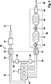
Über den Luftzufuhrkanal
In dem Abgasnachbehandlungssystem
Nicht dargestellt sind für den Betrieb der Brennkraftmaschine
Durch den Betrieb der Brennkraftmaschine
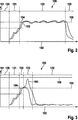
In
Insbesondere im Fall niedriger Motorlasten und Drehzahlen sind neben Luftsystemeingriffen, beispielsweise über die Drosselklappe
Die genannten Maßnahmen beeinflussen neben der Abgastemperatur auch die Zusammensetzung des Abgases, insbesondere dessen Sauerstoffgehalt. Da der Sauerstoffgehalt einen wesentlichen Einfluss auf die Abbrandgeschwindigkeit der in dem Partikelfilter
Der Beladungslevel 0
Speziell während dynamischer Fahrweisen wechselt die Brennkraftmaschine
Fall 1: Während eines innerstädtischen Fahrbetriebs
Fall 2: Während eines innerstädtischen Fahrbetriebs
Fall 3: Während eines außerstädtischen Fahrbetriebs
Fall 4: Während eines außerstädtischen Fahrbetriebs
Case 1: During an urban driving operation
Case 2: During an inner-city driving operation
Case 3: During an extra-urban journey
Case 4: During an extra-urban journey
Angestrebt wird im normalen Fahrbetrieb ein Beladungslevel 1 oder 2
ZITATE ENTHALTEN IN DER BESCHREIBUNG QUOTES INCLUDE IN THE DESCRIPTION
Diese Liste der vom Anmelder aufgeführten Dokumente wurde automatisiert erzeugt und ist ausschließlich zur besseren Information des Lesers aufgenommen. Die Liste ist nicht Bestandteil der deutschen Patent- bzw. Gebrauchsmusteranmeldung. Das DPMA übernimmt keinerlei Haftung für etwaige Fehler oder Auslassungen.This list of the documents listed by the applicant has been generated automatically and is included solely for the better information of the reader. The list is not part of the German patent or utility model application. The DPMA assumes no liability for any errors or omissions.
Zitierte PatentliteraturCited patent literature
- EP 1364110 B1 [0006] EP 1364110 B1 [0006]
Claims (10)
Priority Applications (3)
| Application Number | Priority Date | Filing Date | Title |
|---|---|---|---|
| DE102011006920A DE102011006920A1 (en) | 2011-04-07 | 2011-04-07 | Method for controlling regeneration of diesel particulate filter in exhaust gas passage of diesel engine of vehicle, involves carrying out regeneration process in extended regeneration phase without utilizing post-injections |
| IN505DE2012 IN2012DE00505A (en) | 2011-04-07 | 2012-02-22 | |
| CN201210098924.0A CN102733910B (en) | 2011-04-07 | 2012-04-06 | Method and apparatus for controlling regeneration of particle filter |
Applications Claiming Priority (1)
| Application Number | Priority Date | Filing Date | Title |
|---|---|---|---|
| DE102011006920A DE102011006920A1 (en) | 2011-04-07 | 2011-04-07 | Method for controlling regeneration of diesel particulate filter in exhaust gas passage of diesel engine of vehicle, involves carrying out regeneration process in extended regeneration phase without utilizing post-injections |
Publications (1)
| Publication Number | Publication Date |
|---|---|
| DE102011006920A1 true DE102011006920A1 (en) | 2012-10-11 |
Family
ID=46874929
Family Applications (1)
| Application Number | Title | Priority Date | Filing Date |
|---|---|---|---|
| DE102011006920A Withdrawn DE102011006920A1 (en) | 2011-04-07 | 2011-04-07 | Method for controlling regeneration of diesel particulate filter in exhaust gas passage of diesel engine of vehicle, involves carrying out regeneration process in extended regeneration phase without utilizing post-injections |
Country Status (3)
| Country | Link |
|---|---|
| CN (1) | CN102733910B (en) |
| DE (1) | DE102011006920A1 (en) |
| IN (1) | IN2012DE00505A (en) |
Cited By (3)
| Publication number | Priority date | Publication date | Assignee | Title |
|---|---|---|---|---|
| CN109701329A (en) * | 2019-03-04 | 2019-05-03 | 温州腾骄环保科技有限公司 | A kind of Environmental-protection dust removal device and its method |
| DE102018200253A1 (en) | 2018-01-10 | 2019-07-11 | Bayerische Motoren Werke Aktiengesellschaft | Method for operating an internal combustion engine |
| CN115306523A (en) * | 2022-07-14 | 2022-11-08 | 潍柴动力股份有限公司 | Engine DPF control method and device |
Families Citing this family (4)
| Publication number | Priority date | Publication date | Assignee | Title |
|---|---|---|---|---|
| DE102016207667A1 (en) * | 2016-05-03 | 2017-11-09 | Volkswagen Aktiengesellschaft | Method and device for the regeneration of a particulate filter in a motor vehicle with hybrid drive |
| DE102016120938A1 (en) * | 2016-11-03 | 2018-05-03 | Volkswagen Aktiengesellschaft | Method and device for the regeneration of a particulate filter in a motor vehicle with hybrid drive |
| CN107121450B (en) * | 2017-05-02 | 2021-05-04 | 北京小米移动软件有限公司 | Air purification equipment and detection method and device of filter element |
| JP7020242B2 (en) * | 2018-03-29 | 2022-02-16 | トヨタ自動車株式会社 | Internal combustion engine control device |
Citations (1)
| Publication number | Priority date | Publication date | Assignee | Title |
|---|---|---|---|---|
| EP1364110B1 (en) | 2001-02-23 | 2004-12-29 | Robert Bosch Gmbh | Method and device for controlling an internal combustion engine |
Family Cites Families (4)
| Publication number | Priority date | Publication date | Assignee | Title |
|---|---|---|---|---|
| CN1122756C (en) * | 2001-03-29 | 2003-10-01 | 浙江日月科技贸易有限公司 | High-safety oxygen-enriching device for air distribution of IC engine |
| JPWO2003069137A1 (en) * | 2002-02-12 | 2005-06-02 | いすゞ自動車株式会社 | Exhaust gas purification system and exhaust gas purification method |
| JP4196872B2 (en) * | 2004-04-09 | 2008-12-17 | いすゞ自動車株式会社 | Engine exhaust purification system |
| JP4977993B2 (en) * | 2005-10-19 | 2012-07-18 | いすゞ自動車株式会社 | Diesel engine exhaust purification system |
-
2011
- 2011-04-07 DE DE102011006920A patent/DE102011006920A1/en not_active Withdrawn
-
2012
- 2012-02-22 IN IN505DE2012 patent/IN2012DE00505A/en unknown
- 2012-04-06 CN CN201210098924.0A patent/CN102733910B/en not_active Expired - Fee Related
Patent Citations (1)
| Publication number | Priority date | Publication date | Assignee | Title |
|---|---|---|---|---|
| EP1364110B1 (en) | 2001-02-23 | 2004-12-29 | Robert Bosch Gmbh | Method and device for controlling an internal combustion engine |
Cited By (3)
| Publication number | Priority date | Publication date | Assignee | Title |
|---|---|---|---|---|
| DE102018200253A1 (en) | 2018-01-10 | 2019-07-11 | Bayerische Motoren Werke Aktiengesellschaft | Method for operating an internal combustion engine |
| CN109701329A (en) * | 2019-03-04 | 2019-05-03 | 温州腾骄环保科技有限公司 | A kind of Environmental-protection dust removal device and its method |
| CN115306523A (en) * | 2022-07-14 | 2022-11-08 | 潍柴动力股份有限公司 | Engine DPF control method and device |
Also Published As
| Publication number | Publication date |
|---|---|
| CN102733910A (en) | 2012-10-17 |
| CN102733910B (en) | 2017-04-12 |
| IN2012DE00505A (en) | 2015-06-05 |
Similar Documents
| Publication | Publication Date | Title |
|---|---|---|
| DE102005045294B4 (en) | Method for operating an internal combustion engine | |
| DE10325083B4 (en) | Fuel injection control system for an internal combustion engine | |
| DE10161461B4 (en) | Process and device for the regeneration of particulate filters in diesel engines | |
| DE102010035541B4 (en) | Control of the regeneration time of a diesel particle filter | |
| DE102005017099B4 (en) | Regeneration of a low-emission diesel particulate filter (DPF) | |
| DE102011006920A1 (en) | Method for controlling regeneration of diesel particulate filter in exhaust gas passage of diesel engine of vehicle, involves carrying out regeneration process in extended regeneration phase without utilizing post-injections | |
| AT521448B1 (en) | Process and arrangement of Otto engines with improved particle filtering II | |
| DE102013210896A1 (en) | A method for operating an exhaust aftertreatment and means for controlling an exhaust aftertreatment and exhaust aftertreatment, engine control unit and internal combustion engine with an exhaust aftertreatment | |
| DE102008019383A1 (en) | A method of re-opening combustion-filled channels in diesel particulate filters | |
| WO2009112056A1 (en) | Cylinder pressure guided regeneration operation and operation type change | |
| EP1108862A2 (en) | Method and apparatus for reducing harmful constituents of exhaust gas of a combustion engine | |
| DE102008059698A1 (en) | A method for operating a diesel engine with a nitrogen oxide storage catalyst having emission control system | |
| DE102011105601A1 (en) | System and method for regenerating a particulate matter filter using a catalytic converter as a combustor | |
| DE102010002606A1 (en) | Method for controlling regeneration of diesel particulate filter in exhaust gas passage of diesel engine, involves supplying residual exhaust gas mass flow over butterfly valve to particulate filter due to leakage of supply air | |
| EP1099053A1 (en) | Method and device for controlling an internal combustion engine | |
| WO2020000009A1 (en) | Method and petrol engine arrangement with improved particulate filtering i | |
| DE102004019658B4 (en) | Exhaust emission control device for an internal combustion engine | |
| DE102005025737A1 (en) | Operating process for injection engine involves detecting operating values and producing ratio of nitrogen oxide emission and particle emission as basis for control | |
| EP1584809B1 (en) | Method for regeneration of an exhaust gas aftertreatment device | |
| DE102006002640B4 (en) | Method for operating a particle filter arranged in an exhaust gas area of an internal combustion engine and device for carrying out the method | |
| DE102009032659A1 (en) | Method for limiting emission behavior during transient operation of diesel internal combustion engine, involves determining injected fuel quantity from adapted oxygen set point and injection mold | |
| DE102009008393A1 (en) | Method for regeneration of exhaust gas with exhaust gas aftertreatment device of internal-combustion engine of hybrid vehicle, involves reducing oxygen concentration in exhaust gas independent of driving requirements of vehicle | |
| DE602004011508T2 (en) | REGENERATION OF A PARTICLE FILTER USING A LAMB DAVARIATION | |
| EP1682754A1 (en) | Multi-cylinder internal combustion engine and method for the operation thereof | |
| DE102009045379A1 (en) | Method for controlling regeneration of diesel particle filter in exhaust gas after treatment system of diesel engine, involves lowering temperatures in oxidation catalyst and particle filter below respective target temperatures |
Legal Events
| Date | Code | Title | Description |
|---|---|---|---|
| R119 | Application deemed withdrawn, or ip right lapsed, due to non-payment of renewal fee |