EP1108862A2 - Method and apparatus for reducing harmful constituents of exhaust gas of a combustion engine - Google Patents
Method and apparatus for reducing harmful constituents of exhaust gas of a combustion engine Download PDFInfo
- Publication number
- EP1108862A2 EP1108862A2 EP00126406A EP00126406A EP1108862A2 EP 1108862 A2 EP1108862 A2 EP 1108862A2 EP 00126406 A EP00126406 A EP 00126406A EP 00126406 A EP00126406 A EP 00126406A EP 1108862 A2 EP1108862 A2 EP 1108862A2
- Authority
- EP
- European Patent Office
- Prior art keywords
- exhaust gas
- particle filter
- particle
- control device
- combustion engine
- Prior art date
- Legal status (The legal status is an assumption and is not a legal conclusion. Google has not performed a legal analysis and makes no representation as to the accuracy of the status listed.)
- Granted
Links
Images

Classifications
-
- F—MECHANICAL ENGINEERING; LIGHTING; HEATING; WEAPONS; BLASTING
- F01—MACHINES OR ENGINES IN GENERAL; ENGINE PLANTS IN GENERAL; STEAM ENGINES
- F01N—GAS-FLOW SILENCERS OR EXHAUST APPARATUS FOR MACHINES OR ENGINES IN GENERAL; GAS-FLOW SILENCERS OR EXHAUST APPARATUS FOR INTERNAL COMBUSTION ENGINES
- F01N9/00—Electrical control of exhaust gas treating apparatus
- F01N9/002—Electrical control of exhaust gas treating apparatus of filter regeneration, e.g. detection of clogging
-
- B—PERFORMING OPERATIONS; TRANSPORTING
- B01—PHYSICAL OR CHEMICAL PROCESSES OR APPARATUS IN GENERAL
- B01D—SEPARATION
- B01D53/00—Separation of gases or vapours; Recovering vapours of volatile solvents from gases; Chemical or biological purification of waste gases, e.g. engine exhaust gases, smoke, fumes, flue gases, aerosols
- B01D53/34—Chemical or biological purification of waste gases
- B01D53/92—Chemical or biological purification of waste gases of engine exhaust gases
- B01D53/94—Chemical or biological purification of waste gases of engine exhaust gases by catalytic processes
- B01D53/9404—Removing only nitrogen compounds
- B01D53/9409—Nitrogen oxides
- B01D53/9431—Processes characterised by a specific device
-
- B—PERFORMING OPERATIONS; TRANSPORTING
- B01—PHYSICAL OR CHEMICAL PROCESSES OR APPARATUS IN GENERAL
- B01D—SEPARATION
- B01D53/00—Separation of gases or vapours; Recovering vapours of volatile solvents from gases; Chemical or biological purification of waste gases, e.g. engine exhaust gases, smoke, fumes, flue gases, aerosols
- B01D53/34—Chemical or biological purification of waste gases
- B01D53/92—Chemical or biological purification of waste gases of engine exhaust gases
- B01D53/94—Chemical or biological purification of waste gases of engine exhaust gases by catalytic processes
- B01D53/9495—Controlling the catalytic process
-
- F—MECHANICAL ENGINEERING; LIGHTING; HEATING; WEAPONS; BLASTING
- F01—MACHINES OR ENGINES IN GENERAL; ENGINE PLANTS IN GENERAL; STEAM ENGINES
- F01N—GAS-FLOW SILENCERS OR EXHAUST APPARATUS FOR MACHINES OR ENGINES IN GENERAL; GAS-FLOW SILENCERS OR EXHAUST APPARATUS FOR INTERNAL COMBUSTION ENGINES
- F01N13/00—Exhaust or silencing apparatus characterised by constructional features ; Exhaust or silencing apparatus, or parts thereof, having pertinent characteristics not provided for in, or of interest apart from, groups F01N1/00 - F01N5/00, F01N9/00, F01N11/00
- F01N13/009—Exhaust or silencing apparatus characterised by constructional features ; Exhaust or silencing apparatus, or parts thereof, having pertinent characteristics not provided for in, or of interest apart from, groups F01N1/00 - F01N5/00, F01N9/00, F01N11/00 having two or more separate purifying devices arranged in series
-
- F—MECHANICAL ENGINEERING; LIGHTING; HEATING; WEAPONS; BLASTING
- F01—MACHINES OR ENGINES IN GENERAL; ENGINE PLANTS IN GENERAL; STEAM ENGINES
- F01N—GAS-FLOW SILENCERS OR EXHAUST APPARATUS FOR MACHINES OR ENGINES IN GENERAL; GAS-FLOW SILENCERS OR EXHAUST APPARATUS FOR INTERNAL COMBUSTION ENGINES
- F01N3/00—Exhaust or silencing apparatus having means for purifying, rendering innocuous, or otherwise treating exhaust
- F01N3/02—Exhaust or silencing apparatus having means for purifying, rendering innocuous, or otherwise treating exhaust for cooling, or for removing solid constituents of, exhaust
- F01N3/021—Exhaust or silencing apparatus having means for purifying, rendering innocuous, or otherwise treating exhaust for cooling, or for removing solid constituents of, exhaust by means of filters
- F01N3/023—Exhaust or silencing apparatus having means for purifying, rendering innocuous, or otherwise treating exhaust for cooling, or for removing solid constituents of, exhaust by means of filters using means for regenerating the filters, e.g. by burning trapped particles
- F01N3/0231—Exhaust or silencing apparatus having means for purifying, rendering innocuous, or otherwise treating exhaust for cooling, or for removing solid constituents of, exhaust by means of filters using means for regenerating the filters, e.g. by burning trapped particles using special exhaust apparatus upstream of the filter for producing nitrogen dioxide, e.g. for continuous filter regeneration systems [CRT]
-
- F—MECHANICAL ENGINEERING; LIGHTING; HEATING; WEAPONS; BLASTING
- F01—MACHINES OR ENGINES IN GENERAL; ENGINE PLANTS IN GENERAL; STEAM ENGINES
- F01N—GAS-FLOW SILENCERS OR EXHAUST APPARATUS FOR MACHINES OR ENGINES IN GENERAL; GAS-FLOW SILENCERS OR EXHAUST APPARATUS FOR INTERNAL COMBUSTION ENGINES
- F01N3/00—Exhaust or silencing apparatus having means for purifying, rendering innocuous, or otherwise treating exhaust
- F01N3/02—Exhaust or silencing apparatus having means for purifying, rendering innocuous, or otherwise treating exhaust for cooling, or for removing solid constituents of, exhaust
- F01N3/021—Exhaust or silencing apparatus having means for purifying, rendering innocuous, or otherwise treating exhaust for cooling, or for removing solid constituents of, exhaust by means of filters
- F01N3/033—Exhaust or silencing apparatus having means for purifying, rendering innocuous, or otherwise treating exhaust for cooling, or for removing solid constituents of, exhaust by means of filters in combination with other devices
- F01N3/035—Exhaust or silencing apparatus having means for purifying, rendering innocuous, or otherwise treating exhaust for cooling, or for removing solid constituents of, exhaust by means of filters in combination with other devices with catalytic reactors, e.g. catalysed diesel particulate filters
-
- F—MECHANICAL ENGINEERING; LIGHTING; HEATING; WEAPONS; BLASTING
- F01—MACHINES OR ENGINES IN GENERAL; ENGINE PLANTS IN GENERAL; STEAM ENGINES
- F01N—GAS-FLOW SILENCERS OR EXHAUST APPARATUS FOR MACHINES OR ENGINES IN GENERAL; GAS-FLOW SILENCERS OR EXHAUST APPARATUS FOR INTERNAL COMBUSTION ENGINES
- F01N9/00—Electrical control of exhaust gas treating apparatus
- F01N9/005—Electrical control of exhaust gas treating apparatus using models instead of sensors to determine operating characteristics of exhaust systems, e.g. calculating catalyst temperature instead of measuring it directly
-
- F—MECHANICAL ENGINEERING; LIGHTING; HEATING; WEAPONS; BLASTING
- F02—COMBUSTION ENGINES; HOT-GAS OR COMBUSTION-PRODUCT ENGINE PLANTS
- F02D—CONTROLLING COMBUSTION ENGINES
- F02D21/00—Controlling engines characterised by their being supplied with non-airborne oxygen or other non-fuel gas
- F02D21/06—Controlling engines characterised by their being supplied with non-airborne oxygen or other non-fuel gas peculiar to engines having other non-fuel gas added to combustion air
- F02D21/08—Controlling engines characterised by their being supplied with non-airborne oxygen or other non-fuel gas peculiar to engines having other non-fuel gas added to combustion air the other gas being the exhaust gas of engine
-
- F—MECHANICAL ENGINEERING; LIGHTING; HEATING; WEAPONS; BLASTING
- F02—COMBUSTION ENGINES; HOT-GAS OR COMBUSTION-PRODUCT ENGINE PLANTS
- F02D—CONTROLLING COMBUSTION ENGINES
- F02D41/00—Electrical control of supply of combustible mixture or its constituents
- F02D41/02—Circuit arrangements for generating control signals
- F02D41/021—Introducing corrections for particular conditions exterior to the engine
- F02D41/0235—Introducing corrections for particular conditions exterior to the engine in relation with the state of the exhaust gas treating apparatus
- F02D41/027—Introducing corrections for particular conditions exterior to the engine in relation with the state of the exhaust gas treating apparatus to purge or regenerate the exhaust gas treating apparatus
- F02D41/029—Introducing corrections for particular conditions exterior to the engine in relation with the state of the exhaust gas treating apparatus to purge or regenerate the exhaust gas treating apparatus the exhaust gas treating apparatus being a particulate filter
-
- F—MECHANICAL ENGINEERING; LIGHTING; HEATING; WEAPONS; BLASTING
- F02—COMBUSTION ENGINES; HOT-GAS OR COMBUSTION-PRODUCT ENGINE PLANTS
- F02D—CONTROLLING COMBUSTION ENGINES
- F02D2200/00—Input parameters for engine control
- F02D2200/02—Input parameters for engine control the parameters being related to the engine
- F02D2200/08—Exhaust gas treatment apparatus parameters
- F02D2200/0812—Particle filter loading
-
- F—MECHANICAL ENGINEERING; LIGHTING; HEATING; WEAPONS; BLASTING
- F02—COMBUSTION ENGINES; HOT-GAS OR COMBUSTION-PRODUCT ENGINE PLANTS
- F02D—CONTROLLING COMBUSTION ENGINES
- F02D2250/00—Engine control related to specific problems or objectives
- F02D2250/36—Control for minimising NOx emissions
-
- Y—GENERAL TAGGING OF NEW TECHNOLOGICAL DEVELOPMENTS; GENERAL TAGGING OF CROSS-SECTIONAL TECHNOLOGIES SPANNING OVER SEVERAL SECTIONS OF THE IPC; TECHNICAL SUBJECTS COVERED BY FORMER USPC CROSS-REFERENCE ART COLLECTIONS [XRACs] AND DIGESTS
- Y02—TECHNOLOGIES OR APPLICATIONS FOR MITIGATION OR ADAPTATION AGAINST CLIMATE CHANGE
- Y02T—CLIMATE CHANGE MITIGATION TECHNOLOGIES RELATED TO TRANSPORTATION
- Y02T10/00—Road transport of goods or passengers
- Y02T10/10—Internal combustion engine [ICE] based vehicles
- Y02T10/40—Engine management systems
Definitions
- the invention relates to a method and an apparatus for reducing harmful components in the exhaust gas of an internal combustion engine and particularly affects the particle regeneration of a continuously operating particle reduction device.
- a so-called CRT system Continuous Regenerating Trap
- CRT system Continuous Regenerating Trap
- the incoming raw NOx emissions from the internal combustion engine which are predominantly in the form of NO, are first oxidized to NO 2 on the oxidation catalyst.
- NO 2 is then able to oxidize the particles held in the particle filter, NO 2 being reduced back to NO.
- NO 2 With a sufficiently high NO 2 supply, a satisfactory particle reduction is achieved.
- NOx reduction there is almost no NOx reduction, and the inherently harmful constituent NOx is used to oxidize the particles in the particle filter.
- the invention has for its object a method for the regeneration of Particle filter of a continuously operating particle reduction device and one to create appropriate exhaust gas purification device with which, for example, the new European emissions standard EU-IV is complied with.
- the solutions according to the invention are based on the knowledge that the loading of the particle filter takes a certain time and the time to one certain or critical loading level can be exploited, the NOx content reduce, which gives the exhaust gas a more environmentally friendly quality.
- the method according to claim 1 and the device according to claim 8 are suitable for a raw emission, the NOx content of which is so low that after the conversion of NOx to NO 2 there is too little NO 2 available to remove the particles in the filter oxidize.
- the degree of loading in the particle filter will therefore increase with the disadvantage described at the outset, but in this functional area an exhaust gas with a far reduced NOx content leaves the device. If the degree of loading has reached a certain or critical value, the proportion of NOx in the raw emission is increased. This provides an increased supply of NO 2 in the particle filter in order to reduce the proportion of particles in the particle filter, this reduction being greater than the particle input, so that the degree of loading is reduced again.
- the increased NO or NOx supply can be guaranteed, for example by lowering an exhaust gas recirculation rate, by shifting the start of injection of the main injection or by changing the quantity and beginning of a pre-injection.
- the exhaust gas has a somewhat higher NOx content. If the degree of loading decreases, for example to a certain value, the NOx portion in the raw emission can be reduced again, the exhaust gas having a lower NOx portion in this functional cycle.
- the device according to the invention is also simple and inexpensive manufacturable design that can be controlled in a simple manner and reliable is working.
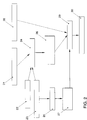
- the internal combustion engine 1 shows the internal combustion engine 1, in particular a diesel internal combustion engine, with several cylinders, to which there is an air intake line 2 and of which there are extend an exhaust pipe 3 in a manner known per se.
- the internal combustion engine 1 are not shown fuel injection valves of a fuel injection device 4 assigned.
- the cylinders are injected directly from the fuel Injectors and with combustion air through the air intake line 2 in one adjustable particular air / fuel ratio, which makes the Combustion operation is guaranteed.
- the cylinders are common to the common through branch line sections, not shown Exhaust pipe 3 connected, which is discharged from the engine 1 Exhaust gas is flowed through in the flow direction 5 indicated by an arrow 5.
- Exhaust pipe 3 In exhaust pipe 3 is a particle reduction system with an oxidation catalytic converter 6 arranged.
- a particle filter 7 arranged in a housing 8.
- the internal combustion engine 1 is assigned an exhaust gas recirculation device 11, which is a the internal combustion engine 1 has a recirculation line 11a that goes from the Exhaust pipe 3 in the flow direction 5 behind the internal combustion engine, if necessary, branches off behind an adjustable exhaust throttle 12 and in the Flow direction 5 upstream of internal combustion engine 1 with air intake line 2 is connected in the flow direction 5 behind a throttle valve 13 in the Air intake line 2.
- a return line 11a is an adjustable exhaust gas recirculation valve 11b arranged, with which the return quantity of the exhaust gas can be controlled or can be regulated, and this by a control line 11c with a generally 14th designated electronic control device is connected, which is a central Processor (CPU) has.
- the throttle valve 13 is also through a control line 13a and possibly also signal line connected to the control device 14.
- a known turbocharger 15 is assigned to internal combustion engine 1, which indicated in the transition area between the internal combustion engine 1 and the Exhaust pipe 3 shown and by a different from the electronic Control device 14 to control line 15a extending to it can be controlled.
- Temperature sensor 16 and a gas pressure sensor 17 arranged by Signal lines 16a, 17a are connected to the electronic control device 14.
- the pressure sensor 17 is the temperature sensor 16 in the Upstream flow direction 5.
- the pressure sensor 17 is part of a measuring device 17b with which the pressure in the Exhaust pipe 3 in the flow direction 5 in front of the oxidation catalytic converter 6 and behind the turbocharger 15 can be determined, a corresponding to the respective gas pressure Pressure signal is generated by means of the signal line 17a of the control or Control device 14 is transmitted and from this as an actual value for the control or Scheme is used.
- the exhaust back pressure can be measured by measuring the fresh air mass opened exhaust gas recirculation valve 11b can be determined. For this is in the Air intake line 2 in the flow direction 5 preferably in front of the throttle valve 13 a hot wire 18 of an air mass meter arranged by a signal line 18a is connected to the control or regulating device 14, the signals thereof as Actual value used.
- the procedure for reducing the harmful components in the exhaust gas is described below. Due to appropriate measures, for example the engine control or an appropriate EGR rate, the NOx portion of the exhaust gas after the conversion of the NO in the oxidation catalytic converter 6 to NO 2 is not sufficient to reduce the particles collected on the particle filter 7 to such a large extent that that the reduction of the particles is larger than the particle entry. As a result, the particle filter 7 is increasingly loaded, the gas counterpressure in the exhaust system 2 upstream of the particle filter 7 increasing. This is monitored by the exhaust gas pressure measuring device 17b. If the exhaust gas back pressure exceeds a certain or critical value, the NOx content of the raw exhaust gas is increased by suitable measures, so that the reduction in the filtered particles is greater than the particle input. If the gas back pressure then drops again below a certain value, the NOx content is reduced again.
- appropriate measures for example the engine control or an appropriate EGR rate
- the exhaust gas expelled from the internal combustion engine 1 can contain a NO x component which corresponds to the above-described reduced value without a NO x reduction device.
- the degree of loading on the particle filter 7 reaches an upper threshold, the proportion of NOx in the raw exhaust gas emission is increased by a corresponding measure to a value which ensures a reduction of the particles in the particle filter. If the exhaust gas back pressure then drops again to a certain value, ie the loading of the particle filter has dropped below a predetermined threshold, the increase in NOx is reduced again and so on.
- the increase in the NOx content can be increased by Lowering the exhaust gas recirculation rate by moving the start of injection forward Main injection, or by changing the quantity and start of the pre-injection can be achieved.
- the threshold for use ie the upper threshold of the particle filter loading, for NO-increasing measures can be selected depending on the loading state of the particle filter 7.
- the NO raw emissions but also the absolute increase in NO emissions due to NO-increasing measures, increase disproportionately, while at idle when the raw NO emissions are doubled, the NO 2 supply in front of the particle filter 7 by 2 to 8 g / h can be increased, at medium pressures of 6 bar, 20 to 100 g / h additional NO emissions are to be expected, so that the return of the particle mass in the particle filter 7 can proceed correspondingly faster.
- higher exhaust gas temperatures are usually also present at higher engine loads, so that the risk of falling below a light-off temperature of the particle reduction system of 200 ° C. is lower.
- a corresponding model can therefore be derived from the context described put up.
Abstract
Description
Die Erfindung bezieht sich auf ein Verfahren und eine Vorrichtung zum Reduzieren schädlicher Bestandteile im Abgas einer Brennkraftmaschine und betrifft insbesondere die Partikelregeneration einer kontinuierlich arbeitenden Partikelminderungsvorrichtung.The invention relates to a method and an apparatus for reducing harmful components in the exhaust gas of an internal combustion engine and particularly affects the particle regeneration of a continuously operating particle reduction device.
Es ist bekannt, zur Verminderung der Partikelemission bei Brennkraftmaschinen, insbesondere Diesel-Brennkraftmaschinen, einen Partikelfilter zu benutzen, der in der Abgasleitung angeordnet ist und die Partikel aus dem durch die Abgasleitung strömenden Abgas filtert. Hierbei werden die Partikel im Partikelfilter zurückgehalten, wo sie sich ansammeln. Diese Ansammlung der Partikel wird als Beladung des Partikelfilters bezeichnet. Diese Beladung führt dazu, daß sich der Partikelfilter mit der Zeit zusetzt und regeneriert werden muß, was durch ein Frei- bzw. Abbrennen der Partikel am Filter erfolgen kann. Die Zündtemperatur von Ruß, aus dem die Partikel hauptsächlich bestehen, liegt bei Partikelfiltern üblicherweise etwa im Bereich von über 550° C.It is known to reduce particle emissions in internal combustion engines, especially diesel engines to use a particulate filter in the Exhaust pipe is arranged and the particles from through the exhaust pipe flowing exhaust filters. The particles are retained in the particle filter, where they accumulate. This accumulation of particles is called the loading of the Particle filter called. This loading means that the particle filter with the Adds time and has to be regenerated, which is caused by a free or burning of the Particles can take place on the filter. The ignition temperature of soot from which the particles mainly exist, usually lies in the range of over with particle filters 550 ° C.
Es ist bereits ein sogenanntes CRT-System (Continuously Regenerating Trap) vorgeschlagen worden, bei dem es sich um eine kontinuierlich reduzierende Partikelminderungsvorrichtung handelt, die einen vorgeschalteten Oxidationskatalysator und einen nachgeschalteten Partikelfilter in der Abgasleitung umfaßt. Am Oxidationskatalysator wird die anströmenden NOx-Rohemissionen der Brennkraftmaschine, die vorwiegend in Form von NO vorliegen, zunächst zu NO2 oxidiert. Das NO2 ist als starkes Oxidationsmittel dann in der Lage, die im Partikelfilter festgehaltenen Partikel zu oxidieren, wobei NO2 wieder zu NO reduziert wird. Bei einem hinreichend hohen NO2-Angebot wird eine befriedigende Partikelverminderung erreicht. Es findet jedoch nahezu keine NOx-Verminderung statt, wobei der an sich schädliche Bestandteil NOx dazu ausgenutzt wird, die Partikel im Partikelfilter zu oxidieren.A so-called CRT system (Continuously Regenerating Trap) has already been proposed, which is a continuously reducing particle reduction device which comprises an upstream oxidation catalytic converter and a downstream particle filter in the exhaust line. The incoming raw NOx emissions from the internal combustion engine, which are predominantly in the form of NO, are first oxidized to NO 2 on the oxidation catalyst. As a strong oxidizing agent, NO 2 is then able to oxidize the particles held in the particle filter, NO 2 being reduced back to NO. With a sufficiently high NO 2 supply, a satisfactory particle reduction is achieved. However, there is almost no NOx reduction, and the inherently harmful constituent NOx is used to oxidize the particles in the particle filter.
Ferner ist bekannt, den NOx-Anteil im Abgas durch eine NOx-Minderungsvorrichtung zu senken, z.B. durch eine Anhebung einer Abgas-Rückführungsmenge, jedoch ergibt sich hierbei folgendes Problem. Wird beim Einsatz einer kontinuierlich arbeitenden Partikelminderungsvorrichtung die NOx Rohemission beispielsweise durch eine Abgas-Rückführungsmenge soweit gemindert, daß gewünschte Grenzwerte für NOx eingehalten werden können, kann im Abgas vor dem Partikelfilter nicht mehr genügend NO2 vorliegen, um eine vollständige Umsetzung des Partikelmassenstroms zu gewährleisten. Eine zunehmende Beladung des Partikelfilters ist damit nicht auszuschließen. Bei sehr hohen Beladungsmengen im Partikelfilter steigt der Abgasgegendruck an, so daß neben einem Kraftstoff-Mehrverbrauch sogar ein Absterben der Brennkraftmaschine droht. Überdies besteht dann bei sehr starker Erwärmung des Partikelfilters die Gefahr der Selbstzündung der Partikel. Bei entsprechend hohen gespeicherten Partikelmengen kann deren unkontrolliertes Abbrennen zu einer Zerstörung des Partikelfilters führen.It is also known to reduce the proportion of NOx in the exhaust gas by means of a NOx reduction device, for example by increasing an exhaust gas recirculation quantity, but this results in the following problem. If, when using a continuously operating particle reduction device, the raw NO x emission is reduced, for example by an exhaust gas recirculation quantity, to such an extent that the desired limit values for NO x can be met, there can no longer be enough NO 2 in the exhaust gas upstream of the particle filter to allow the particle mass flow to be fully implemented guarantee. An increasing loading of the particle filter cannot be ruled out. If the particle filter has very high loads, the exhaust gas back pressure rises, so that, in addition to an increase in fuel consumption, the internal combustion engine may even die. In addition, there is then a risk of self-ignition of the particles if the particle filter is heated very strongly. If the quantity of particles stored is correspondingly high, their uncontrolled burning can lead to the destruction of the particle filter.
Der Erfindung liegt die Aufgabe zugrunde, ein Verfahren zur Regeneration des Partikelfilters einer kontinuierlich arbeitenden Partikelminderungsvorrichtung sowie eine entsprechende Abgasreinigungsvorrichtung zu schaffen, mit denen beispielsweise die neue europäische Abgasnorm EU-IV eingehalten wird.The invention has for its object a method for the regeneration of Particle filter of a continuously operating particle reduction device and one to create appropriate exhaust gas purification device with which, for example, the new European emissions standard EU-IV is complied with.
Diese Aufgabe wird durch die Merkmale des Verfahrens nach Anspruch 1 sowie der
Vorrichtung nach Anspruch 8 gelöst. Bevorzugte Ausführungsformen der Erfindungen
sind Gegenstand der Unteransprüche.This object is achieved by the features of the method according to
Den erfindungsgemäßen Lösungen liegt die Erkenntnis zugrunde, daß die Beladung des Partikelfilters eine bestimmte Zeit in Anspruch nimmt und die Zeit bis zu einem bestimmten oder kritischen Beladungsgrad dazu ausgenutzt werden kann, den NOx-Anteil zu verringern, wodurch das Abgas eine umweltfreundlichere Qualität erhält.The solutions according to the invention are based on the knowledge that the loading of the particle filter takes a certain time and the time to one certain or critical loading level can be exploited, the NOx content reduce, which gives the exhaust gas a more environmentally friendly quality.
Das Verfahren nach Anspruch 1 und die Vorrichtung nach Anspruch 8 eignen sich für
eine Rohemission, deren NOx-Anteil so niedrig ist, daß nach der Umwandlung von NOx
zu NO2 ein zu geringes NO2-Angebot vorhanden ist, um die Partikel im Filter zu
oxidieren. Deshalb wird der Beladungsgrad im Partikelfilter mit dem eingangs
beschriebenen Nachteil zunehmen, wobei jedoch in diesem Funktionsbereich ein
Abgas mit einem weit verminderten NOx-Anteil die Vorrichtung verläßt. Wenn der
Beladungsgrad einen bestimmten oder kritischen Wert angenommen hat, wird der NOx-Anteil
in der Rohemission vergrößert. Hierdurch wird ein erhöhtes NO2-Angebot im
Partikelfilter bereitgestellt, um den Partikelanteil im Partikelfilter zu senken, wobei diese
Senkung größer ist als der Partikeleintrag, so daß der Beladungsgrad wieder verringert
wird. Das erhöhte NO- bzw. NOx-Angebot kann gewährleistet werden, beispielsweise
durch eine Absenkung einer Abgasrückführungsrate, durch Vorverlagerung des
Spritzbeginns der Haupteinspritzung oder durch Änderung von Menge und Beginn einer
Voreinspritzung. Während dieses Funktionszyklusses weist das Abgas einen etwas
höheren NOx-Anteil auf. Wenn der Beladungsgrad sich verringert, z.B. auf einen
bestimmten Wert, kann der NOx-Anteil in der Rohemission wieder verringert werden,
wobei in diesem Funktionszyklus das Abgas einen geringeren NOx-Anteil aufweist.The method according to
Die erfindungsgemäße Vorrichtung ist außerdem von einfacher und kostengünstig herstellbarer Bauweise, die sich in einfacher Weise steuern läßt und funktionssicher arbeitet.The device according to the invention is also simple and inexpensive manufacturable design that can be controlled in a simple manner and reliable is working.
Nachfolgend werden die Erfindung bzw. weitere erfindungsgemäße Funktionskriterien und Maßnahmen sowie durch sie erzielbare Vorteile anhand eines weiteren Ausführungsbeispiels und einer Zeichnung näher erläutert. Es zeigen
- Fig. 1
- eine Brennkraftmaschine mit einer erfindungsgemäßen Vorrichtung zum Reduzieren von schädlichen Bestandteilen im Abgas der Brennkraftmaschine in schematischer Darstellung; und
- Fig. 2
- eine Modellierung eines abgewandelten Ausführungsbeispiels.
- Fig. 1
- an internal combustion engine with an inventive device for reducing harmful components in the exhaust gas of the internal combustion engine in a schematic representation; and
- Fig. 2
- a modeling of a modified embodiment.
Fig. 1 zeigt die Brennkraftmaschine 1, insbesondere eine Diesel-Brennkraftmaschine,
mit mehreren Zylindern, zu denen sich eine Luftansaugleitung 2 und von denen sich
eine Abgasleitung 3 in an sich bekannter Weise erstrecken. Der Brennkraftmaschine 1
sind nicht dargestellte Kraftstoff-Einspritzventile einer Kraftstoff-Einspritzvorrichtung 4
zugeordnet. Die Zylinder werden durch direkte Einspritzung mit Kraftstoff aus den
Einspritzventilen und mit Verbrennungsluft durch die Luftansaugleitung 2 in einem
einstellbaren bestimmten Kraftstoff/Luft-Verhältnis versorgt, wodurch der
Verbrennungsbetrieb gewährleistet ist.1 shows the
Die Zylinder sind durch nicht dargestellte Zweigleitungsabschnitte mit der gemeinsamen
Abgasleitung 3 verbunden, die von dem von der Brennkraftmaschine 1 ausgestoßenen
Abgas in der mit einem Pfeil 5 bezeichneten Strömungsrichtung 5 durchströmt wird. In
der Abgasleitung 3 ist ein Partikelminderungssystem mit einem Oxidationskatalysator 6
angeordnet. In der Strömungsrichtung 5 hinter dem Oxyidationskatalysator 6 ist in der
Abgasleitung 3 ein Partikelfilter 7 in einem Gehäuse 8 angeordnet. The cylinders are common to the common through branch line sections, not shown
Der Brennkraftmaschine 1 ist eine Abgasrückführvorrichtung 11 zugeordnet, die eine
die Brennkraftmaschine 1 umgehende Rückführleitung 11a aufweist, die von der
Abgasleitung 3 in der Strömungsrichtung 5 hinter der Brennkraftmaschine,
gegebenenfalls hinter einer verstellbaren Abgasdrossel 12, abzweigt und in der
Strömungsrichtung 5 vor der Brennkraftmaschine 1 mit der Luftansaugleitung 2
verbunden ist und zwar in der Strömungsrichtung 5 hinter einer Drosselklappe 13 in der
Luftansaugleitung 2. In der Rückführleitung 11a ist ein verstellbares AbgasRückführventil
11b angeordnet, mit dem die Rückführmenge des Abgases steuerbar
oder regelbar ist, und das durch eine Steuerleitung 11c mit einer allgemein mit 14
bezeichneten elektronischen Steuereinrichtung verbunden ist, die einen zentralen
Prozessor (CPU) aufweist. Die Drosselklappe 13 ist ebenfalls durch eine Steuerleitung
13a und gegebenenfalls auch Signalleitung mit der Steuereinrichtung 14 verbunden.The
Der Brennkraftmaschine 1 ist ein an sich bekannter Turbolader 15 zugeordnet, der
andeutungsweise im Übergangsbereich zwischen der Brennkraftmaschine 1 und der
Abgasleitung 3 dargestellt und durch eine sich von der elektronischen
Steuereinrichtung 14 zu ihm erstreckenden Steuerleitung 15a ansteuerbar ist. In der
Abgasleitung 3 sind in der Strömungsrichtung 5 vor dem Oxidationskatalysator 6 ein
Temperatursensor 16 und ein Gasdrucksensor 17 angeordnet, die durch
Signalleitungen 16a, 17a mit der elektronischen Steuereinrichtung 14 verbunden sind.
Vorzugsweise ist der Drucksensor 17 dem Temperatursensor 16 in der
Strömungsrichtung 5 vorgeordnet.A known
Der Drucksensor 17 ist Teil einer Meßvorrichtung 17b, mit der der Druck in der
Abgasleitung 3 in der Strömungsrichtung 5 vor dem Oxidationskatalysator 6 und hinter
dem Turbolader 15 feststellbar ist, wobei ein dem jeweiligen Gasdruck entsprechendes
Drucksignal erzeugt wird, das mittels der Signalleitung 17a der Steuer- oder
Regeleinrichtung 14 übermittelt wird und von dieser als Istwert für die Steuerung oder
Regelung benutzt wird.The pressure sensor 17 is part of a measuring device 17b with which the pressure in the
Alternativ kann der Abgasgegendruck durch eine Messung der Frischluftmasse bei
geöffnetem Abgasrückführventil 11b ermittelt werden. Hierzu ist in der
Luftansaugleitung 2 in der Strömungsrichtung 5 vorzugsweise vor der Drosselklappe 13
ein Hitzdraht 18 eines Luftmassenmessers angeordnet, der durch eine Signalleitung
18a mit der Steuer- oder Regeleinrichtung 14 verbunden ist, die dessen Signale als
Istwert benutzt. Alternatively, the exhaust back pressure can be measured by measuring the fresh air mass
opened exhaust
Mit der Bezugszahl 4a ist eine sich zur Einspritzvorrichtung 4 erstreckende
Steuerleitung bezeichnet, über die die Einspritzvorrichtung 4 zwischen Einstellungen
vor, haupt (mittel) und nach durch die Steuer- oder Regeleinrichtung 14 einstellbar ist.With the
Nachfolgend wird das Verfahren zur Reduzierung der schädlichen Bestandteile im
Abgas beschrieben. Aufgrund entsprechender Maßnahmen, beispielsweise der
Motorsteuerung oder durch eine entsprechende EGR-Rate reicht der NOx-Anteil des
Abgases nach der Umwandlung des NO im Oxidationskatalysator 6 zu NO2 nicht aus,
um die am Partikelfilter 7 gesammelten Partikel in einem so starken Maße zu
reduzieren, daß die Reduktion der Partikel größer ist als der Partikeleintrag. Folglich
wird der Partikelfilter 7 zunehmend beladen, wobei der Gasgegendruck in der
Abgasanlage 2 vor dem Partikelfilter 7 steigt. Dies wird durch die Abgasdruck-Meßvorrichtung
17b überwacht. Wenn der Abgasgegendruck einen bestimmten oder
kritischen Wert übersteigt, wird der NOx-Gehalt des Rohabgases durch geeignete
Maßnahmen erhöht, so daß die Reduzierung der gefilterten Partikel größer ist als der
Partikeleintrag. Wenn der Gasgegendruck dann wieder unter einen bestimmten Wert
fällt, wird NOx-Gehalt wieder verringert.The procedure for reducing the harmful components in the exhaust gas is described below. Due to appropriate measures, for example the engine control or an appropriate EGR rate, the NOx portion of the exhaust gas after the conversion of the NO in the oxidation catalytic converter 6 to NO 2 is not sufficient to reduce the particles collected on the
Im Rahmen der Erfindung kann das aus der Brennkraftmaschine 1 ausgestoßene
Abgas einen NOx-Anteil enthalten, der dem vorbeschriebenen abgesenkten Wert ohne
eine NOx-Verminderungsvorrichtung entspricht. In einem solchen Fall wird dann, wenn
der Beladungsgrad am Partikelfilter 7 eine obere Schwelle erreicht, der NOx-Anteil in
der Abgasrohemission durch eine entsprechende Maßnahme auf einen Wert erhöht,
der eine Reduzierung der Partikel im Partikelfilter gewährleistet. Wenn dann der
Abgasgegendruck wieder auf einen bestimmten Wert fällt, d.h. die Beladung des
Partikelfilters unterhalb einer vorbestimmten Schwelle gefallen ist, wird die NOx-Erhöhung
wieder zurückgenommen und so fort.In the context of the invention, the exhaust gas expelled from the
Im Rahmen der Erfindung kann die Vergrößerung des NOx-Anteils durch eine Absenkung der Abgas-Rückführrate, durch Vorverlagerung des Spritzbeginns der Haupteinspritzung, oder durch Änderung von Menge und Beginn der Voreinspritzung erreicht werden.In the context of the invention, the increase in the NOx content can be increased by Lowering the exhaust gas recirculation rate by moving the start of injection forward Main injection, or by changing the quantity and start of the pre-injection can be achieved.
Zur Verstärkung der Partikelminderung ist es sinnvoll, oberhalb einer applizierbaren
Schwelle der ermittelten Partikelfilterbeladung und oberhalb einer applizierbaren
Schwelle der Abgas- und/oder Partikelfiltertemperatur ein erhöhtes NOx- bzw. NO-Angebot
bereitzustellen, um die im Partikelfilter 7 eingelagerte Partikelmasse stärker zu
senken als der Partikeleintrag.To increase the particle reduction, it makes sense to apply above one
Threshold of the determined particle filter load and above an applicable one
Threshold of the exhaust gas and / or particle filter temperature an increased NOx or NO supply
To provide the particle mass stored in the
Die Einsatzschwelle, d.h. die obere Schwelle der Partikelfilterbeladung, für NO-steigernde
Maßnahmen kann abhängig sein von dem Beladungszustand des
Partikelfilters 7 gewählt werden. Mit zunehmender Last nehmen die NO-Rohemissionen,
aber auch der absolute Anstieg der NO-Emissionen durch NO-steigernde
Maßnahmen überproportional zu, während im Leerlauf bei einer
Verdoppelung der NO-Rohemissionen das NO2-Angebot vor dem Partikelfilter 7 um 2
bis 8 g/h erhöht werden kann, ist bei Mitteldrücken um 6 bar bereits mit 20 bis 100 g/h
NO-Mehremissionen zu rechnen, so daß die Rücknahme der Partikelmasse im
Partikelfilter 7 entsprechend schneller ablaufen kann. Hinzu kommt, daß bei höheren
Motorlasten üblicherweise auch höhere Abgastemperaturen vorliegen, so daß die
Gefahr des Unterschreitens einer Anspringtemperatur des Partikelminderungssystems
von 200 ° C geringer ist.The threshold for use, ie the upper threshold of the particle filter loading, for NO-increasing measures can be selected depending on the loading state of the
Es kann somit beispielsweise vorgeschlagen werden, bei gespeicherten Partikelmassen bis 5 Gramm erst ab 6 bar Mitteldruck NO-steigernde Maßnahmen einzusetzen, während mit zunehmender Beladung der Schwellwert um 1 bar pro 5 Gramm eingelagerter Partikelmasse abnimmt. Selbstverständlich sind aber fahrzeug- und motorabhängig auch Abweichungen möglich.It can thus be proposed, for example, for stored particle masses up to 5 grams only use NO-increasing measures from 6 bar medium pressure, while with increasing loading the threshold value by 1 bar per 5 grams embedded particle mass decreases. Of course, but are vehicle and Deviations possible depending on the engine.
Fig. 2 zeigt eine Modellierung der Partikelspeicherung. Ein in einem entsprechenden
Speicher der Motorsteuerung abgespeichertes Kennfeld 21 der NO-Rohemission, der
Abgasmassenstrom 22 sowie die Temperatur 23 des Vorkatalysators beeinflussen die
Rate 24 der Umwandlung von NO → NO2. Ferner geht die Temperatur 23 des
Vorkatalysators in ein Vorrohrmodell 25 ein, woraus sich die Temperatur 27 am
Partikelfilter ergibt. Die bereits erwähnte Umwandlungsrate 24 bestimmt die tatsächliche
NO2-Emission 26 vor dem Partikelfilter. Der Partikelumsatz 29 im Partikelfilter wird von
der Temperatur 27 am Partikelfilter, der NO2-Emission 26 vor dem Partikelfilter sowie
einem Kennfeld 28 Partikelemissionen beeinflußt.. Der Partikelumsatz 29 schließlich
bestimmt die eingelagerte Partikelmasse 30. Ein entsprechendes Modell läßt sich daher
aus dem geschilderten Zusammenhang aufstellen. 2 shows a modeling of the particle storage. A characteristic diagram 21 of the raw raw emission, the exhaust
- 11
- BrennkraftmaschineInternal combustion engine
- 22nd
- LuftansaugleitungAir intake line
- 33rd
- AbgasleitungExhaust pipe
- 44th
- EinspritzvorrichtungInjector
- 55
- StrömungsrichtungFlow direction
- 66
- OxidationskatalysatorOxidation catalyst
- 77
- PartikelfilterParticle filter
- 88th
- Gehäusecasing
- 1111
- AbgasrückvorrichtungExhaust gas recirculation device
- 11a11a
- RückführleitungReturn line
- 1212th
- AbgasdrosselExhaust throttle
- 1313
- Drosselklappethrottle
- 1414
- SteuereinrichtungControl device
- 1515
- Turboladerturbocharger
- 1616
- TemperatursensorTemperature sensor
- 16a16a
- SignalleitungSignal line
- 1717th
- GasdrucksensorGas pressure sensor
- 17a17a
- SignalleitungSignal line
- 17b17b
- MeßvorrichtungMeasuring device
- 1818th
- HitzdrahtHot wire
- 18a18a
- SignalleitungSignal line
- 2121
- Kennfeld NO-RohemissionMap raw NO emission
- 2222
- AbgasmassenstromExhaust mass flow
- 2323
- Temperatur-VorkatalysatorTemperature pre-catalyst
- 2424th
- NO->NO2-BildungNO-> NO 2 formation
- 2525th
- VorrohrmodellFront tube model
- 2626
- NO2-Emission vor PartikelfilterNO 2 emission before particle filter
- 2727
- Temperatur am PartikelfilterParticulate filter temperature
- 2828
- Kennfeld PartikelemissionMap particle emission
- 2929
- PartikelumsatzParticle turnover
- 3030th
- Eingelagerte PartikelmasseEmbedded particle mass
Claims (15)
Applications Claiming Priority (2)
| Application Number | Priority Date | Filing Date | Title |
|---|---|---|---|
| DE19961166A DE19961166A1 (en) | 1999-12-17 | 1999-12-17 | Method and device for reducing harmful components in the exhaust gas of an internal combustion engine |
| DE19961166 | 1999-12-17 |
Publications (3)
| Publication Number | Publication Date |
|---|---|
| EP1108862A2 true EP1108862A2 (en) | 2001-06-20 |
| EP1108862A3 EP1108862A3 (en) | 2003-11-26 |
| EP1108862B1 EP1108862B1 (en) | 2006-09-13 |
Family
ID=7933211
Family Applications (1)
| Application Number | Title | Priority Date | Filing Date |
|---|---|---|---|
| EP00126406A Expired - Lifetime EP1108862B1 (en) | 1999-12-17 | 2000-12-05 | Method and apparatus for reducing harmful constituents of exhaust gas of a combustion engine |
Country Status (3)
| Country | Link |
|---|---|
| EP (1) | EP1108862B1 (en) |
| AT (1) | ATE339600T1 (en) |
| DE (2) | DE19961166A1 (en) |
Cited By (15)
| Publication number | Priority date | Publication date | Assignee | Title |
|---|---|---|---|---|
| EP1321642A1 (en) * | 2001-12-12 | 2003-06-25 | Mitsubishi Jidosha Kogyo Kabushiki Kaisha | Exhaust emission control device |
| FR2846708A1 (en) * | 2002-11-04 | 2004-05-07 | Siemens Ag | Method of determining the load in a particle filter placed in the exhaust from an internal combustion engine by measuring changes in exhaust gas concentration |
| WO2004046283A1 (en) * | 2002-11-15 | 2004-06-03 | Bp Oil International Limited | Method of reducing particulate emissions |
| FR2864146A1 (en) * | 2003-12-23 | 2005-06-24 | Renault Sas | Real-time determination of the mass of particulates in an automobile exhaust gas filter comprises performing a cycle of operations in which the mass is calculated from the mass determined in the preceding cycle |
| FR2872204A1 (en) * | 2004-06-23 | 2005-12-30 | Peugeot Citroen Automobiles Sa | SYSTEM FOR AIDING THE REGENERATION OF DEPOLLUTION MEANS INTEGRATED IN AN EXHAUST LINE OF AN ENGINE |
| WO2008106164A2 (en) * | 2007-02-28 | 2008-09-04 | Caterpillar Inc. | Particulate regeneration and engine control system |
| US7493755B2 (en) | 2004-06-23 | 2009-02-24 | Peugeot Citroen Automobiles Sa | System for assisting the regeneration of depollution means for a motor vehicle engine |
| EP1990511A3 (en) * | 2007-05-07 | 2009-11-04 | Nissan Motor Co., Ltd. | Exhaust Gas Cleaning Apparatus |
| US7694511B2 (en) | 2004-06-23 | 2010-04-13 | Peugeot Citroen Automobiles Sa | System for controlling depollution means regeneration |
| EP2199170A1 (en) * | 2008-12-18 | 2010-06-23 | Iveco S.p.A. | Method for the activation and the deactivation of the stop and start function in a vehicle, and relative device |
| WO2010094681A1 (en) | 2009-02-18 | 2010-08-26 | Shell Internationale Research Maatschappij B.V. | Use of a lubricating composition with gtl base oil to reduce hydrocarbon emissions |
| GB2486196A (en) * | 2010-12-06 | 2012-06-13 | Gm Global Tech Operations Inc | Reducing exhaust emissions by controlling the exhaust composition entering a filter |
| US8631642B2 (en) | 2009-12-22 | 2014-01-21 | Perkins Engines Company Limited | Regeneration assist calibration |
| EP2406473A4 (en) * | 2009-03-12 | 2015-10-21 | Volvo Lastvagnar Ab | Operating method for an exhaust aftertreatment system and exhaust aftertreatment system |
| EP2826968A4 (en) * | 2012-03-14 | 2016-01-20 | Toyota Motor Co Ltd | Exhaust gas purification device for internal combustion engine |
Families Citing this family (5)
| Publication number | Priority date | Publication date | Assignee | Title |
|---|---|---|---|---|
| DE10130633B4 (en) * | 2001-06-26 | 2010-10-21 | Man Nutzfahrzeuge Ag | Process for the regeneration of a particulate filter |
| DE10223736A1 (en) * | 2002-05-28 | 2003-12-11 | Man Nutzfahrzeuge Ag | Device for reducing soot particles contained in the exhaust gas of a vehicle diesel engine |
| JP4075573B2 (en) | 2002-06-13 | 2008-04-16 | 株式会社デンソー | Exhaust gas purification device for internal combustion engine |
| DE10357893A1 (en) * | 2003-12-11 | 2005-07-07 | Deutz Ag | Oxidizing catalyst with variable activity |
| DE102008014528A1 (en) * | 2008-03-15 | 2009-09-17 | Hjs Fahrzeugtechnik Gmbh & Co. Kg | Method for determining the loading state of a particle filter switched into the exhaust gas line of an internal combustion engine and device for reducing the particle emission of an internal combustion engine |
Citations (3)
| Publication number | Priority date | Publication date | Assignee | Title |
|---|---|---|---|---|
| EP0879946A2 (en) * | 1997-05-21 | 1998-11-25 | Toyota Jidosha Kabushiki Kaisha | An internal combustion engine |
| WO1999009307A1 (en) * | 1997-08-13 | 1999-02-25 | Johnson Matthey Public Limited Company | Improvements in emissions control |
| JPH11336530A (en) * | 1998-05-21 | 1999-12-07 | Nissan Motor Co Ltd | Exhaust emission control device for diesel engine |
Family Cites Families (1)
| Publication number | Priority date | Publication date | Assignee | Title |
|---|---|---|---|---|
| JP3899534B2 (en) * | 1995-08-14 | 2007-03-28 | トヨタ自動車株式会社 | Exhaust gas purification method for diesel engine |
-
1999
- 1999-12-17 DE DE19961166A patent/DE19961166A1/en not_active Withdrawn
-
2000
- 2000-12-05 DE DE50013462T patent/DE50013462D1/en not_active Expired - Lifetime
- 2000-12-05 EP EP00126406A patent/EP1108862B1/en not_active Expired - Lifetime
- 2000-12-05 AT AT00126406T patent/ATE339600T1/en not_active IP Right Cessation
Patent Citations (3)
| Publication number | Priority date | Publication date | Assignee | Title |
|---|---|---|---|---|
| EP0879946A2 (en) * | 1997-05-21 | 1998-11-25 | Toyota Jidosha Kabushiki Kaisha | An internal combustion engine |
| WO1999009307A1 (en) * | 1997-08-13 | 1999-02-25 | Johnson Matthey Public Limited Company | Improvements in emissions control |
| JPH11336530A (en) * | 1998-05-21 | 1999-12-07 | Nissan Motor Co Ltd | Exhaust emission control device for diesel engine |
Non-Patent Citations (2)
| Title |
|---|
| COOPER B J ET AL: "ROLE OF NO IN DIESEL PARTICULATE EMISSION CONTROL" DEVELOPMENTS IN DIESEL PARTICULATE CONTROL SYSTEMS, WARRENDALE, PA, US, 1989, Seiten 171-183, XP000889454 * |
| PATENT ABSTRACTS OF JAPAN vol. 2000, no. 03, 30. März 2000 (2000-03-30) & JP 11 336530 A (NISSAN MOTOR CO LTD), 7. Dezember 1999 (1999-12-07) * |
Cited By (27)
| Publication number | Priority date | Publication date | Assignee | Title |
|---|---|---|---|---|
| US6708487B2 (en) | 2001-12-12 | 2004-03-23 | Mitsubishi Jidosha Kogyo Kabushiki Kaisha | Exhaust emission control device |
| EP1321642A1 (en) * | 2001-12-12 | 2003-06-25 | Mitsubishi Jidosha Kogyo Kabushiki Kaisha | Exhaust emission control device |
| DE10251224B4 (en) * | 2002-11-04 | 2005-09-15 | Siemens Ag | Method for determining a loading of a particle filter in the exhaust gas tract of an internal combustion engine |
| FR2846708A1 (en) * | 2002-11-04 | 2004-05-07 | Siemens Ag | Method of determining the load in a particle filter placed in the exhaust from an internal combustion engine by measuring changes in exhaust gas concentration |
| US7825076B2 (en) | 2002-11-15 | 2010-11-02 | Bp Oil International Limited | Method of reducing particulate emissions |
| WO2004046283A1 (en) * | 2002-11-15 | 2004-06-03 | Bp Oil International Limited | Method of reducing particulate emissions |
| AU2003283540B2 (en) * | 2002-11-15 | 2009-06-11 | Bp Oil International Limited | Method of reducing particulate emissions |
| FR2864146A1 (en) * | 2003-12-23 | 2005-06-24 | Renault Sas | Real-time determination of the mass of particulates in an automobile exhaust gas filter comprises performing a cycle of operations in which the mass is calculated from the mass determined in the preceding cycle |
| US7319928B2 (en) | 2003-12-23 | 2008-01-15 | Renault S.A.S. | Method for real time determination of the mass of particles in a particle filter of a motor vehicle |
| WO2005064143A1 (en) * | 2003-12-23 | 2005-07-14 | Renault S.A.S. | Method for real time determination of the mass of particles in a particle filter of a motor vehicle |
| US7694511B2 (en) | 2004-06-23 | 2010-04-13 | Peugeot Citroen Automobiles Sa | System for controlling depollution means regeneration |
| FR2872204A1 (en) * | 2004-06-23 | 2005-12-30 | Peugeot Citroen Automobiles Sa | SYSTEM FOR AIDING THE REGENERATION OF DEPOLLUTION MEANS INTEGRATED IN AN EXHAUST LINE OF AN ENGINE |
| WO2006005865A1 (en) * | 2004-06-23 | 2006-01-19 | Peugeot Citroen Automobiles Sa | System for assisting regeneration of pollution management means integrated in an engine exhaust line |
| US7493755B2 (en) | 2004-06-23 | 2009-02-24 | Peugeot Citroen Automobiles Sa | System for assisting the regeneration of depollution means for a motor vehicle engine |
| WO2008106164A2 (en) * | 2007-02-28 | 2008-09-04 | Caterpillar Inc. | Particulate regeneration and engine control system |
| WO2008106164A3 (en) * | 2007-02-28 | 2008-12-11 | Caterpillar Inc | Particulate regeneration and engine control system |
| EP1990511A3 (en) * | 2007-05-07 | 2009-11-04 | Nissan Motor Co., Ltd. | Exhaust Gas Cleaning Apparatus |
| US8127536B2 (en) | 2007-05-07 | 2012-03-06 | Nissan Motor Co., Ltd. | Exhaust gas cleaning apparatus |
| EP2199170A1 (en) * | 2008-12-18 | 2010-06-23 | Iveco S.p.A. | Method for the activation and the deactivation of the stop and start function in a vehicle, and relative device |
| WO2010094681A1 (en) | 2009-02-18 | 2010-08-26 | Shell Internationale Research Maatschappij B.V. | Use of a lubricating composition with gtl base oil to reduce hydrocarbon emissions |
| EP2406473A4 (en) * | 2009-03-12 | 2015-10-21 | Volvo Lastvagnar Ab | Operating method for an exhaust aftertreatment system and exhaust aftertreatment system |
| US9399937B2 (en) | 2009-03-12 | 2016-07-26 | Volvo Lastvagnar Ab | Operating method for an exhaust aftertreatment system and exhaust aftertreatment system |
| EP2406473B1 (en) | 2009-03-12 | 2018-02-28 | Volvo Lastvagnar AB | Operating method for an exhaust aftertreatment system and exhaust aftertreatment system |
| US8631642B2 (en) | 2009-12-22 | 2014-01-21 | Perkins Engines Company Limited | Regeneration assist calibration |
| US8776501B2 (en) | 2009-12-22 | 2014-07-15 | Perkins Engines Company Limited | Regeneration assist calibration |
| GB2486196A (en) * | 2010-12-06 | 2012-06-13 | Gm Global Tech Operations Inc | Reducing exhaust emissions by controlling the exhaust composition entering a filter |
| EP2826968A4 (en) * | 2012-03-14 | 2016-01-20 | Toyota Motor Co Ltd | Exhaust gas purification device for internal combustion engine |
Also Published As
| Publication number | Publication date |
|---|---|
| ATE339600T1 (en) | 2006-10-15 |
| DE50013462D1 (en) | 2006-10-26 |
| EP1108862A3 (en) | 2003-11-26 |
| DE19961166A1 (en) | 2001-06-21 |
| EP1108862B1 (en) | 2006-09-13 |
Similar Documents
| Publication | Publication Date | Title |
|---|---|---|
| EP1108862B1 (en) | Method and apparatus for reducing harmful constituents of exhaust gas of a combustion engine | |
| EP1336039B1 (en) | Method and device for the control of an exhaust treatment system | |
| DE10161461B4 (en) | Process and device for the regeneration of particulate filters in diesel engines | |
| EP1364110B1 (en) | Method and device for controlling an internal combustion engine | |
| DE10161396B4 (en) | Process for the regeneration of a particulate filter provided in a diesel engine | |
| EP1087114B1 (en) | Method for controlling the regeneration of a particulate filter | |
| DE102006007122A1 (en) | Operating process for internal combustion engine involves reporting suitable combinations of engine operating values for preset nitrogen oxide emission value | |
| DE102013003701A1 (en) | Method for controlling regeneration of particulate filter, involves setting air ratio for adjusting supply of hydrocarbon during regeneration of particulate filter, by which conversion of nitrogen oxides is takes place | |
| DE102010040678A1 (en) | A method of monitoring pollutant conversion capability in an exhaust aftertreatment system | |
| DE102009007764A1 (en) | Method for operating an internal combustion engine with an emission control system | |
| EP1559880B1 (en) | Device and method for reducing harmful components in the exhaust gas of an internal combustion engine, especially a Diesel-internal-combustion engine | |
| DE102004052655A1 (en) | Pressure monitor for a diesel particulate filter | |
| WO2010060503A1 (en) | Method for operating a diesel engine having an exhaust gas cleaning system comprising a nitrogen oxide storage catalytic converter | |
| DE60002652T2 (en) | Control method of a particle filter and control method of an internal combustion engine | |
| EP2088296A2 (en) | Method for regenerating a particle filter arranged in an exhaust system of a vehicle diesel motor | |
| WO2000071879A1 (en) | Method and device for controlling an internal combustion engine | |
| EP1099465B1 (en) | Process and apparatus for purifying the exhaust gas of an internal combustion engine | |
| DE60102337T2 (en) | System for supporting the regeneration of a particulate filter in a self-ignited internal combustion engine | |
| DE102009046151A1 (en) | Method for limiting temperature of particulate filter in exhaust gas duct of diesel engine during basic mode of operation of engine, involves switching particulate filter from basic mode of operation to regeneration mode of operation | |
| DE102005035168B4 (en) | Method and system for regenerating an exhaust aftertreatment device | |
| DE102005032457A1 (en) | Method and device for controlling or controlling the Rußabbrandgeschwindigkeit | |
| EP4095364B1 (en) | Method for operating a combustion engine | |
| EP1495796A1 (en) | Reduction of nitrogen dioxide emissions in a continuous regenerative filter for soot particles | |
| DE10315467A1 (en) | Exhaust emission control system for an internal combustion engine and exhaust emission control method | |
| EP1541818B1 (en) | Oxidation catalyst with variable activity |
Legal Events
| Date | Code | Title | Description |
|---|---|---|---|
| PUAI | Public reference made under article 153(3) epc to a published international application that has entered the european phase |
Free format text: ORIGINAL CODE: 0009012 |
|
| AK | Designated contracting states |
Kind code of ref document: A2 Designated state(s): AT BE CH CY DE DK ES FI FR GB GR IE IT LI LU MC NL PT SE TR |
|
| AX | Request for extension of the european patent |
Free format text: AL;LT;LV;MK;RO;SI |
|
| PUAL | Search report despatched |
Free format text: ORIGINAL CODE: 0009013 |
|
| AK | Designated contracting states |
Kind code of ref document: A3 Designated state(s): AT BE CH CY DE DK ES FI FR GB GR IE IT LI LU MC NL PT SE TR |
|
| AX | Request for extension of the european patent |
Extension state: AL LT LV MK RO SI |
|
| RIC1 | Information provided on ipc code assigned before grant |
Ipc: 7F 02D 21/08 B Ipc: 7F 01N 11/00 B Ipc: 7B 01D 53/94 B Ipc: 7F 01N 9/00 B Ipc: 7F 02D 35/00 B Ipc: 7F 01N 3/023 B Ipc: 7F 01N 3/035 A Ipc: 7F 02D 41/02 B |
|
| 17P | Request for examination filed |
Effective date: 20040526 |
|
| AKX | Designation fees paid |
Designated state(s): AT BE CH CY DE DK ES FI FR GB GR IE IT LI LU MC NL PT SE TR |
|
| GRAP | Despatch of communication of intention to grant a patent |
Free format text: ORIGINAL CODE: EPIDOSNIGR1 |
|
| GRAS | Grant fee paid |
Free format text: ORIGINAL CODE: EPIDOSNIGR3 |
|
| GRAA | (expected) grant |
Free format text: ORIGINAL CODE: 0009210 |
|
| AK | Designated contracting states |
Kind code of ref document: B1 Designated state(s): AT BE CH CY DE DK ES FI FR GB GR IE IT LI LU MC NL PT SE TR |
|
| PG25 | Lapsed in a contracting state [announced via postgrant information from national office to epo] |
Ref country code: NL Free format text: LAPSE BECAUSE OF FAILURE TO SUBMIT A TRANSLATION OF THE DESCRIPTION OR TO PAY THE FEE WITHIN THE PRESCRIBED TIME-LIMIT Effective date: 20060913 Ref country code: GB Free format text: LAPSE BECAUSE OF FAILURE TO SUBMIT A TRANSLATION OF THE DESCRIPTION OR TO PAY THE FEE WITHIN THE PRESCRIBED TIME-LIMIT Effective date: 20060913 Ref country code: FI Free format text: LAPSE BECAUSE OF FAILURE TO SUBMIT A TRANSLATION OF THE DESCRIPTION OR TO PAY THE FEE WITHIN THE PRESCRIBED TIME-LIMIT Effective date: 20060913 Ref country code: IE Free format text: LAPSE BECAUSE OF FAILURE TO SUBMIT A TRANSLATION OF THE DESCRIPTION OR TO PAY THE FEE WITHIN THE PRESCRIBED TIME-LIMIT Effective date: 20060913 |
|
| REG | Reference to a national code |
Ref country code: GB Ref legal event code: FG4D Free format text: NOT ENGLISH |
|
| REG | Reference to a national code |
Ref country code: CH Ref legal event code: EP |
|
| REG | Reference to a national code |
Ref country code: IE Ref legal event code: FG4D Free format text: LANGUAGE OF EP DOCUMENT: GERMAN |
|
| REF | Corresponds to: |
Ref document number: 50013462 Country of ref document: DE Date of ref document: 20061026 Kind code of ref document: P |
|
| PG25 | Lapsed in a contracting state [announced via postgrant information from national office to epo] |
Ref country code: DK Free format text: LAPSE BECAUSE OF FAILURE TO SUBMIT A TRANSLATION OF THE DESCRIPTION OR TO PAY THE FEE WITHIN THE PRESCRIBED TIME-LIMIT Effective date: 20061213 Ref country code: SE Free format text: LAPSE BECAUSE OF FAILURE TO SUBMIT A TRANSLATION OF THE DESCRIPTION OR TO PAY THE FEE WITHIN THE PRESCRIBED TIME-LIMIT Effective date: 20061213 |
|
| PG25 | Lapsed in a contracting state [announced via postgrant information from national office to epo] |
Ref country code: ES Free format text: LAPSE BECAUSE OF FAILURE TO SUBMIT A TRANSLATION OF THE DESCRIPTION OR TO PAY THE FEE WITHIN THE PRESCRIBED TIME-LIMIT Effective date: 20061224 |
|
| PG25 | Lapsed in a contracting state [announced via postgrant information from national office to epo] |
Ref country code: LI Free format text: LAPSE BECAUSE OF NON-PAYMENT OF DUE FEES Effective date: 20061231 Ref country code: BE Free format text: LAPSE BECAUSE OF NON-PAYMENT OF DUE FEES Effective date: 20061231 Ref country code: MC Free format text: LAPSE BECAUSE OF NON-PAYMENT OF DUE FEES Effective date: 20061231 Ref country code: CH Free format text: LAPSE BECAUSE OF NON-PAYMENT OF DUE FEES Effective date: 20061231 |
|
| NLV1 | Nl: lapsed or annulled due to failure to fulfill the requirements of art. 29p and 29m of the patents act | ||
| PG25 | Lapsed in a contracting state [announced via postgrant information from national office to epo] |
Ref country code: PT Free format text: LAPSE BECAUSE OF FAILURE TO SUBMIT A TRANSLATION OF THE DESCRIPTION OR TO PAY THE FEE WITHIN THE PRESCRIBED TIME-LIMIT Effective date: 20070302 |
|
| GBV | Gb: ep patent (uk) treated as always having been void in accordance with gb section 77(7)/1977 [no translation filed] |
Effective date: 20060913 |
|
| REG | Reference to a national code |
Ref country code: IE Ref legal event code: FD4D |
|
| ET | Fr: translation filed | ||
| PLBE | No opposition filed within time limit |
Free format text: ORIGINAL CODE: 0009261 |
|
| STAA | Information on the status of an ep patent application or granted ep patent |
Free format text: STATUS: NO OPPOSITION FILED WITHIN TIME LIMIT |
|
| REG | Reference to a national code |
Ref country code: CH Ref legal event code: PL |
|
| 26N | No opposition filed |
Effective date: 20070614 |
|
| BERE | Be: lapsed |
Owner name: VOLKSWAGEN A.G. Effective date: 20061231 |
|
| PG25 | Lapsed in a contracting state [announced via postgrant information from national office to epo] |
Ref country code: AT Free format text: LAPSE BECAUSE OF NON-PAYMENT OF DUE FEES Effective date: 20061205 |
|
| PG25 | Lapsed in a contracting state [announced via postgrant information from national office to epo] |
Ref country code: GR Free format text: LAPSE BECAUSE OF FAILURE TO SUBMIT A TRANSLATION OF THE DESCRIPTION OR TO PAY THE FEE WITHIN THE PRESCRIBED TIME-LIMIT Effective date: 20061214 |
|
| PG25 | Lapsed in a contracting state [announced via postgrant information from national office to epo] |
Ref country code: LU Free format text: LAPSE BECAUSE OF NON-PAYMENT OF DUE FEES Effective date: 20061205 Ref country code: TR Free format text: LAPSE BECAUSE OF FAILURE TO SUBMIT A TRANSLATION OF THE DESCRIPTION OR TO PAY THE FEE WITHIN THE PRESCRIBED TIME-LIMIT Effective date: 20060913 |
|
| PG25 | Lapsed in a contracting state [announced via postgrant information from national office to epo] |
Ref country code: CY Free format text: LAPSE BECAUSE OF FAILURE TO SUBMIT A TRANSLATION OF THE DESCRIPTION OR TO PAY THE FEE WITHIN THE PRESCRIBED TIME-LIMIT Effective date: 20060913 |
|
| REG | Reference to a national code |
Ref country code: FR Ref legal event code: PLFP Year of fee payment: 16 |
|
| REG | Reference to a national code |
Ref country code: FR Ref legal event code: PLFP Year of fee payment: 17 |
|
| PGFP | Annual fee paid to national office [announced via postgrant information from national office to epo] |
Ref country code: FR Payment date: 20161230 Year of fee payment: 17 |
|
| PGFP | Annual fee paid to national office [announced via postgrant information from national office to epo] |
Ref country code: DE Payment date: 20161231 Year of fee payment: 17 |
|
| PGFP | Annual fee paid to national office [announced via postgrant information from national office to epo] |
Ref country code: IT Payment date: 20161230 Year of fee payment: 17 |
|
| REG | Reference to a national code |
Ref country code: DE Ref legal event code: R119 Ref document number: 50013462 Country of ref document: DE |
|
| REG | Reference to a national code |
Ref country code: FR Ref legal event code: ST Effective date: 20180831 |
|
| PG25 | Lapsed in a contracting state [announced via postgrant information from national office to epo] |
Ref country code: FR Free format text: LAPSE BECAUSE OF NON-PAYMENT OF DUE FEES Effective date: 20180102 Ref country code: DE Free format text: LAPSE BECAUSE OF NON-PAYMENT OF DUE FEES Effective date: 20180703 Ref country code: IT Free format text: LAPSE BECAUSE OF NON-PAYMENT OF DUE FEES Effective date: 20171205 |