EP1584452A2 - Verfahren zum Herstellen eines formstabilen, hohlkörperförmigen Elementes mit einem Bodenbereich und Verwendung eines solchen Elementes - Google Patents
Verfahren zum Herstellen eines formstabilen, hohlkörperförmigen Elementes mit einem Bodenbereich und Verwendung eines solchen Elementes Download PDFInfo
- Publication number
- EP1584452A2 EP1584452A2 EP05002759A EP05002759A EP1584452A2 EP 1584452 A2 EP1584452 A2 EP 1584452A2 EP 05002759 A EP05002759 A EP 05002759A EP 05002759 A EP05002759 A EP 05002759A EP 1584452 A2 EP1584452 A2 EP 1584452A2
- Authority
- EP
- European Patent Office
- Prior art keywords
- piece
- tubing
- narrowing
- shaped
- thermoformable
- Prior art date
- Legal status (The legal status is an assumption and is not a legal conclusion. Google has not performed a legal analysis and makes no representation as to the accuracy of the status listed.)
- Granted
Links
- 238000000034 method Methods 0.000 title claims description 37
- 239000000463 material Substances 0.000 claims abstract description 51
- 239000004033 plastic Substances 0.000 claims abstract description 22
- 239000004744 fabric Substances 0.000 claims abstract description 12
- 238000001816 cooling Methods 0.000 claims abstract description 7
- 238000010438 heat treatment Methods 0.000 claims abstract description 7
- 239000000835 fiber Substances 0.000 claims description 11
- 238000004519 manufacturing process Methods 0.000 claims description 10
- 239000004743 Polypropylene Substances 0.000 claims description 9
- -1 polypropylene Polymers 0.000 claims description 9
- 229920001155 polypropylene Polymers 0.000 claims description 9
- 239000002184 metal Substances 0.000 claims description 8
- 229920000049 Carbon (fiber) Polymers 0.000 claims description 6
- 239000004917 carbon fiber Substances 0.000 claims description 6
- VNWKTOKETHGBQD-UHFFFAOYSA-N methane Chemical compound C VNWKTOKETHGBQD-UHFFFAOYSA-N 0.000 claims description 6
- UCKMPCXJQFINFW-UHFFFAOYSA-N Sulphide Chemical compound [S-2] UCKMPCXJQFINFW-UHFFFAOYSA-N 0.000 claims description 3
- 239000003365 glass fiber Substances 0.000 claims description 3
- 229920001169 thermoplastic Polymers 0.000 claims description 3
- 229920001187 thermosetting polymer Polymers 0.000 claims description 3
- 239000004416 thermosoftening plastic Substances 0.000 claims description 3
- 238000005507 spraying Methods 0.000 claims description 2
- 238000003825 pressing Methods 0.000 claims 1
- 230000000087 stabilizing effect Effects 0.000 claims 1
- 230000006641 stabilisation Effects 0.000 abstract 1
- 238000011105 stabilization Methods 0.000 abstract 1
- 239000010410 layer Substances 0.000 description 6
- 239000002131 composite material Substances 0.000 description 5
- 239000011152 fibreglass Substances 0.000 description 4
- 230000008901 benefit Effects 0.000 description 3
- 238000002347 injection Methods 0.000 description 3
- 239000007924 injection Substances 0.000 description 3
- 230000001419 dependent effect Effects 0.000 description 2
- 238000001746 injection moulding Methods 0.000 description 2
- 230000002093 peripheral effect Effects 0.000 description 2
- 229920000728 polyester Polymers 0.000 description 2
- 230000002028 premature Effects 0.000 description 2
- 238000007639 printing Methods 0.000 description 2
- 230000002787 reinforcement Effects 0.000 description 2
- 230000003014 reinforcing effect Effects 0.000 description 2
- 238000000926 separation method Methods 0.000 description 2
- 238000010792 warming Methods 0.000 description 2
- CWYNVVGOOAEACU-UHFFFAOYSA-N Fe2+ Chemical compound [Fe+2] CWYNVVGOOAEACU-UHFFFAOYSA-N 0.000 description 1
- 210000001015 abdomen Anatomy 0.000 description 1
- 230000003321 amplification Effects 0.000 description 1
- 239000011248 coating agent Substances 0.000 description 1
- 238000000576 coating method Methods 0.000 description 1
- 230000000694 effects Effects 0.000 description 1
- 239000000155 melt Substances 0.000 description 1
- 238000002844 melting Methods 0.000 description 1
- 230000008018 melting Effects 0.000 description 1
- 238000000465 moulding Methods 0.000 description 1
- 238000003199 nucleic acid amplification method Methods 0.000 description 1
- 238000002360 preparation method Methods 0.000 description 1
- 238000007493 shaping process Methods 0.000 description 1
- 239000002356 single layer Substances 0.000 description 1
- 239000002689 soil Substances 0.000 description 1
- 239000000243 solution Substances 0.000 description 1
- 238000003856 thermoforming Methods 0.000 description 1
- 238000009966 trimming Methods 0.000 description 1
Images


Classifications
-
- B—PERFORMING OPERATIONS; TRANSPORTING
- B29—WORKING OF PLASTICS; WORKING OF SUBSTANCES IN A PLASTIC STATE IN GENERAL
- B29C—SHAPING OR JOINING OF PLASTICS; SHAPING OF MATERIAL IN A PLASTIC STATE, NOT OTHERWISE PROVIDED FOR; AFTER-TREATMENT OF THE SHAPED PRODUCTS, e.g. REPAIRING
- B29C67/00—Shaping techniques not covered by groups B29C39/00 - B29C65/00, B29C70/00 or B29C73/00
- B29C67/0014—Shaping techniques not covered by groups B29C39/00 - B29C65/00, B29C70/00 or B29C73/00 for shaping tubes or blown tubular films
- B29C67/0018—Turning tubes inside out
-
- B—PERFORMING OPERATIONS; TRANSPORTING
- B29—WORKING OF PLASTICS; WORKING OF SUBSTANCES IN A PLASTIC STATE IN GENERAL
- B29C—SHAPING OR JOINING OF PLASTICS; SHAPING OF MATERIAL IN A PLASTIC STATE, NOT OTHERWISE PROVIDED FOR; AFTER-TREATMENT OF THE SHAPED PRODUCTS, e.g. REPAIRING
- B29C53/00—Shaping by bending, folding, twisting, straightening or flattening; Apparatus therefor
- B29C53/14—Twisting
-
- B—PERFORMING OPERATIONS; TRANSPORTING
- B29—WORKING OF PLASTICS; WORKING OF SUBSTANCES IN A PLASTIC STATE IN GENERAL
- B29C—SHAPING OR JOINING OF PLASTICS; SHAPING OF MATERIAL IN A PLASTIC STATE, NOT OTHERWISE PROVIDED FOR; AFTER-TREATMENT OF THE SHAPED PRODUCTS, e.g. REPAIRING
- B29C57/00—Shaping of tube ends, e.g. flanging, belling or closing; Apparatus therefor, e.g. collapsible mandrels
- B29C57/10—Closing
-
- B—PERFORMING OPERATIONS; TRANSPORTING
- B29—WORKING OF PLASTICS; WORKING OF SUBSTANCES IN A PLASTIC STATE IN GENERAL
- B29C—SHAPING OR JOINING OF PLASTICS; SHAPING OF MATERIAL IN A PLASTIC STATE, NOT OTHERWISE PROVIDED FOR; AFTER-TREATMENT OF THE SHAPED PRODUCTS, e.g. REPAIRING
- B29C70/00—Shaping composites, i.e. plastics material comprising reinforcements, fillers or preformed parts, e.g. inserts
- B29C70/04—Shaping composites, i.e. plastics material comprising reinforcements, fillers or preformed parts, e.g. inserts comprising reinforcements only, e.g. self-reinforcing plastics
- B29C70/28—Shaping operations therefor
- B29C70/30—Shaping by lay-up, i.e. applying fibres, tape or broadsheet on a mould, former or core; Shaping by spray-up, i.e. spraying of fibres on a mould, former or core
- B29C70/302—Details of the edges of fibre composites, e.g. edge finishing or means to avoid delamination
-
- B—PERFORMING OPERATIONS; TRANSPORTING
- B29—WORKING OF PLASTICS; WORKING OF SUBSTANCES IN A PLASTIC STATE IN GENERAL
- B29C—SHAPING OR JOINING OF PLASTICS; SHAPING OF MATERIAL IN A PLASTIC STATE, NOT OTHERWISE PROVIDED FOR; AFTER-TREATMENT OF THE SHAPED PRODUCTS, e.g. REPAIRING
- B29C70/00—Shaping composites, i.e. plastics material comprising reinforcements, fillers or preformed parts, e.g. inserts
- B29C70/68—Shaping composites, i.e. plastics material comprising reinforcements, fillers or preformed parts, e.g. inserts by incorporating or moulding on preformed parts, e.g. inserts or layers, e.g. foam blocks
- B29C70/86—Incorporated in coherent impregnated reinforcing layers, e.g. by winding
- B29C70/865—Incorporated in coherent impregnated reinforcing layers, e.g. by winding completely encapsulated
-
- F—MECHANICAL ENGINEERING; LIGHTING; HEATING; WEAPONS; BLASTING
- F04—POSITIVE - DISPLACEMENT MACHINES FOR LIQUIDS; PUMPS FOR LIQUIDS OR ELASTIC FLUIDS
- F04D—NON-POSITIVE-DISPLACEMENT PUMPS
- F04D13/00—Pumping installations or systems
- F04D13/02—Units comprising pumps and their driving means
- F04D13/021—Units comprising pumps and their driving means containing a coupling
- F04D13/024—Units comprising pumps and their driving means containing a coupling a magnetic coupling
- F04D13/025—Details of the can separating the pump and drive area
-
- F—MECHANICAL ENGINEERING; LIGHTING; HEATING; WEAPONS; BLASTING
- F04—POSITIVE - DISPLACEMENT MACHINES FOR LIQUIDS; PUMPS FOR LIQUIDS OR ELASTIC FLUIDS
- F04D—NON-POSITIVE-DISPLACEMENT PUMPS
- F04D13/00—Pumping installations or systems
- F04D13/02—Units comprising pumps and their driving means
- F04D13/06—Units comprising pumps and their driving means the pump being electrically driven
- F04D13/0606—Canned motor pumps
- F04D13/0626—Details of the can
-
- F—MECHANICAL ENGINEERING; LIGHTING; HEATING; WEAPONS; BLASTING
- F04—POSITIVE - DISPLACEMENT MACHINES FOR LIQUIDS; PUMPS FOR LIQUIDS OR ELASTIC FLUIDS
- F04D—NON-POSITIVE-DISPLACEMENT PUMPS
- F04D13/00—Pumping installations or systems
- F04D13/02—Units comprising pumps and their driving means
- F04D13/06—Units comprising pumps and their driving means the pump being electrically driven
- F04D13/0606—Canned motor pumps
- F04D13/0633—Details of the bearings
-
- F—MECHANICAL ENGINEERING; LIGHTING; HEATING; WEAPONS; BLASTING
- F04—POSITIVE - DISPLACEMENT MACHINES FOR LIQUIDS; PUMPS FOR LIQUIDS OR ELASTIC FLUIDS
- F04D—NON-POSITIVE-DISPLACEMENT PUMPS
- F04D13/00—Pumping installations or systems
- F04D13/02—Units comprising pumps and their driving means
- F04D13/06—Units comprising pumps and their driving means the pump being electrically driven
- F04D13/0606—Canned motor pumps
- F04D13/064—Details of the magnetic circuit
-
- B—PERFORMING OPERATIONS; TRANSPORTING
- B29—WORKING OF PLASTICS; WORKING OF SUBSTANCES IN A PLASTIC STATE IN GENERAL
- B29K—INDEXING SCHEME ASSOCIATED WITH SUBCLASSES B29B, B29C OR B29D, RELATING TO MOULDING MATERIALS OR TO MATERIALS FOR MOULDS, REINFORCEMENTS, FILLERS OR PREFORMED PARTS, e.g. INSERTS
- B29K2105/00—Condition, form or state of moulded material or of the material to be shaped
- B29K2105/06—Condition, form or state of moulded material or of the material to be shaped containing reinforcements, fillers or inserts
-
- B—PERFORMING OPERATIONS; TRANSPORTING
- B29—WORKING OF PLASTICS; WORKING OF SUBSTANCES IN A PLASTIC STATE IN GENERAL
- B29L—INDEXING SCHEME ASSOCIATED WITH SUBCLASS B29C, RELATING TO PARTICULAR ARTICLES
- B29L2031/00—Other particular articles
- B29L2031/748—Machines or parts thereof not otherwise provided for
- B29L2031/7496—Pumps
Definitions
- the invention relates to a method for producing a dimensionally stable, hollow body-shaped element with a bottom portion.
- B tubular element to make with a bottom area at one end.
- Such Element can be used, for example, as a canned pot for an electric wet air motor or as a separating calotte in an electromagnetic drive motor used, for example for driving a centrifugal pump.
- the element is usually deep-drawn from a ferrous metal or injection molded from plastic.
- Such a way of production is particularly expensive because in particular the tools for their production for carrying out the deep-drawing process or the injection molding cause extremely high tooling costs. These costs are therefore only acceptable if larger numbers of items required are.
- the object of the invention is a method for manufacturing a dimensionally stable, hollow body-shaped element with a bottom portion to provide which method compared to conventional Manufacturing process significant cost benefits for his Implementation, in particular with regard to small series sizes and which allows hollow body elements with increased mechanical To produce strength.
- the method according to the invention it is possible to more cost effective Way as previously a dimensionally stable, z. B. produce tubular element, the method is especially for quantitatively smaller Series production is suitable. This is due to the fact that the high Cost of making molds for corresponding thermoforming and injection molds are eliminated. Furthermore, the invention is Process itself in a simple way and with simple Means feasible because only simple and mostly already existing Tools can be used. Another advantage exists in that produced by the method according to the invention from plastic dimensionally stable elements in hollow body form also for higher mechanical Strength claims are suitable, so that such elements z. B. as so-called canned tubes or Trennkalotten for electrical Engines, for example, for driving in particular centrifugal pumps used can be used. Other examples For the elements according to the invention are housing parts for many purposes, especially head and turbulentgepurmaschineusemaschinen for multi-level Centrifugal pumps.
- a fabric material or a non-woven material Fiberglass or carbon fiber used.
- a material can, if it for training z. B. a tubular member formed in a preform subsequently with a coating of plastic material, z. B. polypropylene, be provided, which, for example can be done by an injection process.
- the fabric material or the nonwoven material also be a hybrid material, the z. Example, glass fiber as a non-hot mouldable material content and z.
- B. Polypropylene fiber contains as a thermoformable material content.
- the narrowing of the tube piece brought to the required length in a desired location can easily by Twisting of the piece of tubing in itself take place about its longitudinal axis, whereby the narrowing occurs automatically.
- the narrowing but also by attaching a ring or a Fadenverknotung take place at the desired location of the hose piece.
- the narrowing of the hose section in the region of its longitudinal center be carried out, making two substantially the same length Length sections of the hose piece arise.
- the one Length section over the other length section inverted to a To form a two-ply hose piece. It can further so be proceeded that at the non - narrowed end of the narrowed piece of tubing an annular connection component with a cylindrical portion is inserted, such that the cylindrical Section of this component between the two superimposed Length sections of the hose piece is located.
- a sleeve-shaped Component be used, such that the center of this component with the longitudinal center axis of the element to be produced coincides.
- This component can be, for example, a bearing bush and made of metal or plastic.
- a so-called Canned pot manufactured for a wet-running electric motor which motor in turn is used to drive centrifugal pumps can be used.
- Such a canned pot is thus a composite building part and in terms of its wall surfaces liquid-tight and met by the way, due to the appropriate choice of material for the tissue or nonwoven material as reinforcing insert also the required higher mechanical strength values.
- hose 1 made of flexible tissue or Nonwoven material provided which material later with at least a layer of a thermoformable plastic are provided can, wherein the length L of the tube piece 1 in dependence of the length dimension of the finished hollow body-shaped element selected becomes.
- This length dimension L is understandably dependent on which purpose the item is intended for.
- the hose piece 1 of predetermined length is then connected to a Spot 2 narrowed between its ends.
- a narrowing can according to FIG. 2 by turning a longitudinal section of the Hose piece about its longitudinal axis according to the arrow 2a, for example, at least 60 ° - 180 °.
- FIG. 2 causes a twisting an automatic narrowing of the hose piece at point 2.
- the effect of narrowing or twisting exists in that an at least partial preformation of a ground area 3 for the later, finished element arises, the bottom area so closed or has a central hole, as below becomes clear.
- narrowing or twisting e.g. two longitudinal sections 4 and 5 of the hose piece 1 formed.
- a preferred location 2 of the hose piece 1 is located in the longitudinal center of the piece of tubing, leaving two substantially the same length Length sections 4 and 5 are formed.
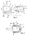
- the next step consists of Figure 3 is that the one Length section 5 according to the arrows 6 over the other length section 4 is slipped, thereby forming a certain preform of a pot becomes.
- the final preform z. B. a pot shape of Hose piece 1. It is understood that the outer shape of the mold 7 or of the dome corresponding to that inner shape, which the finished, tubular element should have.
- the process steps after Figs. 1 and 2 can also be combined with each other by the narrowing or twisting then takes place when a longitudinal section 4 of the hose piece has already been pushed onto the tool 7 is.
- this pot shape is through Application of heat and subsequent cooling in conjunction with the application of a thermoformable plastic material and / or in connection with an already existing in the hose piece 1, resilient and thermoformable plastic material secured or stabilized.
- a thermoformable plastic material which is located on the mold Hose piece is irradiated with heat all around, as it is with 9 in Figure 3 is indicated schematically.
- the heat application can also done in a different way, for example by internal warming of the tool 7 or in an oven.
- a preferred heating temperature covers a range of about 200 ° C to 400 ° C melts the thermoformable plastic material and closes the not thermoformable material of the hose piece 1 in itself as a reinforcing insert one. After a reasonable period of warming takes place cooling in an appropriate manner, leaving a composite component originated.
- This finishing can be the final length of the hollow body-shaped element 1 is e.g. is made by trimming and that in the bottom portion 10th the element is provided a central bore.
- the fabric material or nonwoven material for the tube piece 1 can be structured differently.
- it can consist of a non-thermoformable material, for. B. fiberglass or carbon fiber (carbon fiber).
- the one on the Mold 7 located preform with a plastic layer warm deformable material eg. B. thermoplastic or thermosetting Plastic, z. Polypropylene, polypropylene sulfide or polyester, Mistake.
- a plastic layer can also or additionally be applied to the inside of the preform.
- the mold 7 with inner channels and corresponding Be provided outlet openings (not shown).
- the fabric material or the Nonwoven material to be a hybrid material.
- it consists of one non-deformable fiber content from z.
- glass fiber or carbon fiber and a thermoformable fiber portion of thermoplastic or thermosetting fibers, eg. B. polypropylene, polypropylene sulfide or polyester.
- the two aforementioned material embodiments for the tube piece 1 or for the preform can be combined with each other. That is, the fabric material or the nonwoven material may be a hybrid material which subsequently, So after its shaping on the mold 7, still with at least one plastic layer is provided.
- non-thermoformable material is to be understood as meaning that this is a material whose melting point is so high to carry out this material during the heat application does not melt the process of the invention.
- Term “warm moldable material” to be understood that this is Material is one that in the further above specified temperature range for the application of heat molten is or will be.
- This can be done with a multipart printing tool be achieved, of which only a component in Fig. 3, for example shown and designated 19.
- This printing tool for example can be moved according to the double arrow 20, also heating medium 19a for a sole and / or additional heat application for have the above purpose.
- FIG. 4 shows a supplementary method step.
- an annular connecting member 11 is used, which on the not narrowed end portion of the double-layered hose piece 1 is provided is.
- This connection component 11 has a cylindrical section 11 a, which are superimposed on each other between the two Length sections 4 and 5 of the hose piece 1 is located. Only for better understanding are the two lengths 4 and 5 with Distance from each other and from the section 11 a of the connection component 11th shown; in fact, all these parts are naturally connected.
- the connection component has a radial section 11b on, for example in the form of a flange, with which the finished Element can be mounted in a larger unit, for example on a part in an electric drive motor (not shown).
- This connection component can be made of metal or plastic.
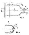
- FIG. 5 shows an alternative for narrowing the length of hose at the Position 2.
- a ring 12 for example, formed as a clip can be.
- the ring 12 can, or the rings can be made of plastic or metal.
- a Fadenverknotung (not shown) are applied, with which usually a Closed bottom portion 10 is formed.
- Figure 6 shows a further alternative embodiment of a tubular or pot-shaped element, which according to the inventive method will be produced.
- a sleeve-shaped Component 13 is used, such that the center of this component with the longitudinal central axis 14 of the element to be produced together falls.
- This sleeve-shaped component is used to form a special axial passage in the bottom portion 10 of the tubular Element.
- the sleeve-shaped Component 13 advantageously be a bearing bush and from a corresponding Warehouse metal exist. This can be a metal, but also a Plastic can be chosen.
- sleeve-shaped member 13 may also be above-mentioned ring 12 (or more rings) are used to the hose piece 1 in the region of the sleeve-shaped component narrow. At the same time by the application of the ring 12 or a plurality of rings causes the sleeve-shaped member 13 in its position also during the production process of the cup-shaped element is secured.
- FIG. 7 shows the example use of an element prepared as described above, in the form of a canned pot 15, which is used in a wet-running electric motor (not shown). Wet-running motors are known to be used to drive centrifugal pumps.
- FIG. 7 shows the finished form of the so-called canned pot 15. It can be seen that in the bottom region 10 a component 13 is used as a bearing bush whose central axis coincides with the longitudinal central axis of the canned pot 15 and which is additionally secured in the bottom region 10 with a ring 12.
- the connection component 11th on which is integrated with its axial portion 11 a between the longitudinal sections 4 and 5 stationary.
- the peripheral wall and the bottom portion of the canned pot formed by the lengths 4 and 5 contain integrated and heat-applied reinforcement formed from the non-thermoformable exemplified fiberglass material of the fabric material or nonwoven material of the length of tubing. This amplification is indicated by dashed lines in FIG. 7 and denoted by 21.
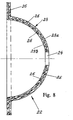
- Fig. 8 shows a so-called separation cap 22, which is used for a so-called magnetic drive, which is electrically operated in a known manner and can also be used for driving centrifugal pumps.
- Such magnetic drives are z.
- the separating caps are numbered 15 and 3, respectively.
- the separating cap consists of one hollow, substantially a cup-forming hemispherical wall part 23, which in the case shown here consists of two wall layers 23a and 23b from z.
- polypropylene has been formed, but after the heat application merged into a single layer, with a central passage 24 and with a circumferential Flange part 25, which may also be omitted.
- the Separator after its preparation also an internal reinforcement 26th made of a non-thermoformable material, eg. Fiberglass or carbon fiber, on and is thus a composite component.
- the hollow body-shaped material produced by the method described above Element can also be used as a housing part for the be used for a variety of purposes.
- such Housing parts as head housing parts and / or foot housing parts for Multi-stage centrifugal pumps suitable.
Landscapes
- Engineering & Computer Science (AREA)
- Mechanical Engineering (AREA)
- General Engineering & Computer Science (AREA)
- Chemical & Material Sciences (AREA)
- Composite Materials (AREA)
- Structures Of Non-Positive Displacement Pumps (AREA)
- Blow-Moulding Or Thermoforming Of Plastics Or The Like (AREA)
- Processing And Handling Of Plastics And Other Materials For Molding In General (AREA)
Abstract
Description
- Figur 1
- eine Seitenansicht eines Schlauchstückes,
- Figur 2
- eine Seitenansicht des Schlauchstückes nach dem ersten Verfahrensschritt,
- Figur 3
- eine Seitenansicht auf das Schlauchstück nach einem weiteren Verfahrensschritt,
- Figuren 4, 5 und 6
- jeweils einen Axialschnitt zur Darstellung noch weiterer Verfahrensschritte,
- Figur 7
- einen Axialschnitt durch einen Spaltrohrtopf für einen elektrischen Antriebsmotor, wobei der Spaltrohrtopf gemäß dem erfindungsgemäßen Verfahren herstellbar ist.
- Figur 8
- einen Axialschnitt durch eine Trennkalotte für einen Elektromagnetantrieb, wobei die Trennkalotte gemäß dem erfindungsgemäßen Verfahren herstellbar ist.
Fig. 8 zeigt eine so genannte Trennkalotte 22, die für einen so genannten Magnetantrieb verwendet wird, der in bekannter Weise elektrisch betrieben wird und ebenfalls zum Antreiben von Kreiselpumpen eingesetzt werden kann. Derartige Magnetantriebe sind z. B. in den beiden US-Patentschriften 3 803 432 und 4 043 706 beschrieben, auf die zum allgemeinen Verständnis dieser Antriebe hierdurch Bezug genommen wird. Darin sind die Trennkalotten (separating wall) mit 15 bzw. 3 beziffert.
Claims (16)
- Verfahren zum Herstellen eines formstabilen, hohlkörperförmigen Elementes mit einem Bodenbereich, gekennzeichnet durch die folgenden Verfahrensschritte:a. Vorsehen eines Schlauchstückes aus einem nachgiebigen Gewebe- oder Faservliesmaterial,b. Verengen des Schlauchstückes im Durchmesser an einer Stelle seiner Länge zur mindestens teilweisen Vorbildung des Bodenbereiches für das hohlkörperförmige Element,c. Vorformen des verengten Schlauchstückes in eine Topfform durch Aufbringen dieses Schlauchstückes auf ein Formwerkzeug, dessen Außenform der Innenform des hohlkörperförmigen Elementes entspricht, undd. Formstabilisieren der vorgeformten Topfform des Schlauchstückes auf dem Formwerkzeug durch Erwärmen und Abkühlen des Schlauchstückes und/oder durch Aufbringen einer Kunststoffschicht auf mindestens eine Seite des Gewebe- oder Faservliesmaterials.
- Verfahren nach Anspruch 1, dadurch gekennzeichnet, dass als das Gewebematerial ein Hybridmaterial verwendet wird, das einen nicht warm formbaren Faseranteil und einen warm formbaren Faseranteil aufweist.
- Verfahren nach Anspruch 1, dadurch gekennzeichnet, dass als das Faservliesmaterial ein Hybridmaterial verwendet wird, das einen nicht warm formbaren Faseranteil und einen warm formbaren Faseranteil aufweist.
- Verfahren nach Anspruch 2 oder 3, dadurch gekennzeichnet, dass der nicht warm formbare Faseranteil eine Glas- oder Kohlefaser ist, und dass der warm formbare Faseranteil ein Polypropylen oder ein Polypropylensulfid in Faserform ist.
- Verfahren nach Anspruch 1, dadurch gekennzeichnet, dass die Kunststoffschicht, die auf das Gewebe- oder Faservliesmaterial aufgebracht wird, durch Aufspritzen eines erwärmten thermoplastischen oder duroplastischen Kunststoffmaterials auf das hohlkörperförmige Schlauchstück und durch Druckanwendung auf das aufgespritzte Kunststoffmaterial hergestellt wird.
- Verfahren nach einem der Ansprüche 1 bis 5, dadurch gekennzeichnet, dass das Verengen des Schlauchstückes durch Verdrehen wenigstens eines Längenabschnittes des Schlauchstückes um seine Längsachse erfolgt.
- Verfahren nach einem der Ansprüche 1 bis 5, dadurch gekennzeichnet, dass das Verengen des Schlauchstückes durch Anbringen eines Ringes erfolgt.
- Verfahren nach einem der Ansprüche 1 bis 5, dadurch gekennzeichnet, dass das Verengen des Schlauchstückes durch Anbringen einer Fadenverknotung erfolgt.
- Verfahren nach einem der Ansprüche 1 bis 8, dadurch gekennzeichnet, dass das Verengen des Schlauchstückes im Bereich seiner Längsmitte durchgeführt wird, wodurch zwei Längenabschnitte des Schlauchstückes entstehen, und dass der eine Längenabschnitt über den anderen Längenabschnitt gestülpt wird, um ein doppellagiges Schlauchstück zu bilden.
- Verfahren nach Anspruch 1, dadurch gekennzeichnet, dass das Erwärmen des hohlkörperförmig vorgeformten Schlauchstückes bei einer Temperatur von 200° C bis 400° C durchgeführt wird.
- Verfahren nach einem der Ansprüche 1 bis 9, dadurch gekennzeichnet, dass im Bereich der Verengungsstelle des verengten Schlauchstückes zur Ausbildung eines axialen Durchganges im Bodenbereich des Elementes ein hülsenförmiges Bauteil eingesetzt wird, derart, dass das Zentrum dieses hülsenförmigen Bauteiles mit der Längsmittelachse des herzustellenden, hohlkörperförmigen Elementes zusammen fällt.
- Verfahren nach Anspruch 11, dadurch gekennzeichnet, dass als hülsenförmiges Bauteil ein solches aus Metall oder Kunststoff verwendet wird.
- Verfahren nach Anspruch 11 oder 12, dadurch gekennzeichnet, dass als hülsenförmiges Bauteil eine Lagerbuchse verwendet wird.
- Verfahren nach Anspruch 9, dadurch gekennzeichnet, dass an dem nicht verengten Endbereich des verengten Schlauchstückes ein ringförmiges Anschlussbauteil mit einem zylindrischen Abschnitt eingesetzt wird, derart, dass sich dieser zylindrische Abschnitt zwischen den beiden übereinander gestülpten Längenabschnitten des Schlauchstückes befindet.
- Verwendung eines formstabilen, hohlkörperförmigen Elementes mit einem Bodenbereich (10), hergestellt nach wenigstens einem der Ansprüche 1 bis 14, als Spaltrohrtopf (15) für einen elektrischen Nasslaufmotor.
- Verwendung eines formstabilen, hohlkörperförmigen Elementes mit einem Bodenbereich, hergestellt nach wenigstens einem der Ansprüche 1 bis 14, als Trennkalotte (22) für einen elektrischen Magnetantriebsmotor.
Applications Claiming Priority (2)
| Application Number | Priority Date | Filing Date | Title |
|---|---|---|---|
| DE102004017418A DE102004017418A1 (de) | 2004-04-08 | 2004-04-08 | Verfahren zum Herstellen eines formstabilen, hohlkörperförmigen Elementes mit einem Bodenbereich und Verwendung eines solchen Elementes |
| DE102004017418 | 2004-04-08 |
Publications (3)
| Publication Number | Publication Date |
|---|---|
| EP1584452A2 true EP1584452A2 (de) | 2005-10-12 |
| EP1584452A3 EP1584452A3 (de) | 2007-01-17 |
| EP1584452B1 EP1584452B1 (de) | 2011-11-02 |
Family
ID=34895530
Family Applications (1)
| Application Number | Title | Priority Date | Filing Date |
|---|---|---|---|
| EP05002759A Expired - Lifetime EP1584452B1 (de) | 2004-04-08 | 2005-02-10 | Verfahren zum Herstellen eines formstabilen, hohlkörperförmigen Elementes mit einem Bodenbereich und Verwendung eines solchen Elementes |
Country Status (3)
| Country | Link |
|---|---|
| EP (1) | EP1584452B1 (de) |
| AT (1) | ATE531510T1 (de) |
| DE (1) | DE102004017418A1 (de) |
Cited By (5)
| Publication number | Priority date | Publication date | Assignee | Title |
|---|---|---|---|---|
| CN100462567C (zh) * | 2006-05-22 | 2009-02-18 | 上海熊猫机械(集团)有限公司 | 水冷节能水泵 |
| WO2010040518A3 (de) * | 2008-10-07 | 2010-11-04 | Wilo Se | Verfahren und vorrichtung zur herstellung hochbelastbarer kunstoffformteile mit hohlprofil |
| FR2995557A1 (fr) * | 2012-09-18 | 2014-03-21 | Aircelle Sa | Procede de fabrication de pieces composites, installation de fabrication mettant en oeuvre un tel procede, et pieces composites ainsi fabriquees |
| EP2040352B2 (de) † | 2007-09-21 | 2014-11-19 | Grundfos Management A/S | Spaltrohr sowie Verfahren zum Herstellen eines Spaltrohres |
| EP4348053A1 (de) * | 2021-05-27 | 2024-04-10 | KSB SE & Co. KGaA | Verfahren zur herstellung eines spaltrohrs bzw. eines spaltrohrtopfes für eine nassläuferpumpe sowie nassläuferpumpe mit spaltrohr bzw. spaltrohrtopf |
Families Citing this family (3)
| Publication number | Priority date | Publication date | Assignee | Title |
|---|---|---|---|---|
| DE102007045108B4 (de) * | 2007-09-20 | 2009-06-18 | Leichtbau-Zentrum Sachsen Gmbh | Verfahren zur Herstellung von Radfelgen aus textilem Schlauch und Radfelge, hergestellt aus textilem Schlauch |
| PL2607710T3 (pl) | 2011-12-23 | 2015-08-31 | Grundfos Holding As | Mokrobieżna pompa wirnikowa |
| DE102019134334A1 (de) * | 2019-12-13 | 2021-06-17 | Wilo Se | Spaltrohr für eine Nassläuferpumpe und Verfahren zu dessen Herstellung |
Family Cites Families (8)
| Publication number | Priority date | Publication date | Assignee | Title |
|---|---|---|---|---|
| GB904307A (en) * | 1960-08-17 | 1962-08-29 | Yokohama Rubber Co Ltd | A floating ship-fender |
| DE1217600B (de) * | 1961-06-19 | 1966-05-26 | Continental Gummi Werke Ag | Verfahren und Vorrichtung zum Herstellen von Rollbaelgen fuer Luftfedern |
| US3408439A (en) * | 1965-03-03 | 1968-10-29 | Mansfield Tire And Rubber Comp | Method for shaping reinforced flexible diaphragms |
| CH478650A (de) * | 1969-02-04 | 1969-09-30 | Contraves Ag | Verfahren zur Herstellung einer armierten Kunstharz-Ummantelung auf einem Formkern |
| US4079755A (en) * | 1976-05-04 | 1978-03-21 | Lans Gerald J V D | Inflatable pipe plug |
| EP0060157A3 (de) * | 1981-02-25 | 1984-08-01 | Albany International Corp. | Hochdruckgehäuse |
| DE4404235C1 (de) * | 1994-02-10 | 1995-01-05 | Urenco Deutschland Gmbh | Verfahren zum Herstellen eines Spalttopfes aus Faserverbundwerkstoff |
| DE19625797B4 (de) * | 1995-07-08 | 2005-01-27 | Volkswagen Ag | Verfahren zur Herstellung eines Rads |
-
2004
- 2004-04-08 DE DE102004017418A patent/DE102004017418A1/de not_active Ceased
-
2005
- 2005-02-10 EP EP05002759A patent/EP1584452B1/de not_active Expired - Lifetime
- 2005-02-10 AT AT05002759T patent/ATE531510T1/de active
Non-Patent Citations (1)
| Title |
|---|
| None |
Cited By (6)
| Publication number | Priority date | Publication date | Assignee | Title |
|---|---|---|---|---|
| CN100462567C (zh) * | 2006-05-22 | 2009-02-18 | 上海熊猫机械(集团)有限公司 | 水冷节能水泵 |
| EP2040352B2 (de) † | 2007-09-21 | 2014-11-19 | Grundfos Management A/S | Spaltrohr sowie Verfahren zum Herstellen eines Spaltrohres |
| WO2010040518A3 (de) * | 2008-10-07 | 2010-11-04 | Wilo Se | Verfahren und vorrichtung zur herstellung hochbelastbarer kunstoffformteile mit hohlprofil |
| FR2995557A1 (fr) * | 2012-09-18 | 2014-03-21 | Aircelle Sa | Procede de fabrication de pieces composites, installation de fabrication mettant en oeuvre un tel procede, et pieces composites ainsi fabriquees |
| WO2014044963A3 (fr) * | 2012-09-18 | 2014-05-08 | Aircelle | Procede de fabrication de pieces composites, installation de fabrication mettant en oeuvre un tel procede |
| EP4348053A1 (de) * | 2021-05-27 | 2024-04-10 | KSB SE & Co. KGaA | Verfahren zur herstellung eines spaltrohrs bzw. eines spaltrohrtopfes für eine nassläuferpumpe sowie nassläuferpumpe mit spaltrohr bzw. spaltrohrtopf |
Also Published As
| Publication number | Publication date |
|---|---|
| ATE531510T1 (de) | 2011-11-15 |
| DE102004017418A1 (de) | 2005-11-03 |
| EP1584452A3 (de) | 2007-01-17 |
| EP1584452B1 (de) | 2011-11-02 |
Similar Documents
| Publication | Publication Date | Title |
|---|---|---|
| DE69428899T2 (de) | Durch spritzgiessen geformtes kunststoffrad für fahrrad | |
| EP0185839B1 (de) | Schaumstoff-Schallabsorptionskörper | |
| DE4108786A1 (de) | Kolben fuer axial- und radialkolbenmaschinen | |
| DE3100192C2 (de) | ||
| DE823344C (de) | Verfahren zum Formen oder Stauchen bzw. Umboerdeln von Befestigungsmitteln aus thermoplastischen Kunststoffen, insbesondere fuer Schuhwerk | |
| DE10236829B4 (de) | Lagerschale für ein Kugelgelenk und Verfahren zu deren Herstellung | |
| DE102015007047B4 (de) | Verfahren und Vorrichtung zur Herstellung eines mit Druck beaufschlagbaren Behälters | |
| DE102007060081B4 (de) | Anordnung aus Trägerteil und Gewindeeinsatz, Verfahren zum Herstellen der Anordnung und Vorrichtung zum Spritzgießen des Gewindeeinsatzes | |
| EP1584452A2 (de) | Verfahren zum Herstellen eines formstabilen, hohlkörperförmigen Elementes mit einem Bodenbereich und Verwendung eines solchen Elementes | |
| DE102014014296A1 (de) | Hohlprofilbauteil aus einem faserverstärkten thermoplastischen Kunststoff | |
| DE69514035T2 (de) | Verfahren zur Herstellung eines Rohres aus thermoplastischem Kunststoff | |
| DE29705522U1 (de) | Kunststoffummantelung für den Zangengriff einer Zange | |
| EP0554214A1 (de) | Verfahren zur Herstellung einer implantierbaren Gelenkschale | |
| EP3033966B1 (de) | Bürste und Verfahren zu deren Herstellung | |
| DE1479468A1 (de) | Verfahren und Vorrichtung zur Herstellung von Gegenstaenden aus Kunststoff | |
| DE102017211625B4 (de) | Verfahren zur Herstellung einer Lagerbuchse, Lagerbuchse sowie Lenker für eine Radaufhängung eines Kraftfahrzeuges | |
| DE60003284T2 (de) | Thermoplastischer fahrradrahmen und verfahren zum herstellen desselben | |
| EP1484162A1 (de) | Verfahren zur Herstellung eines Kunststoffkörpers sowie Behälter | |
| DE19744361A1 (de) | Kunststoff-Filter, insbesondere Kraftstoff-Filter | |
| DE69320904T2 (de) | Rohrförmiges Bauteil hergestellt aus Verbundwerkstoff | |
| DE2418931A1 (de) | Verfahren zum formen eines pneumatischen reifens mit breiter laufflaeche | |
| AT394156B (de) | Verfahren zur herstellung eines tragfaehigen koerpers, insbesondere fahrzeugreifens | |
| EP3463795B1 (de) | Verfahren zur herstellung eines ringförmig geschlossenen endlosschlauches und endlosschlauch | |
| DE102007036639A1 (de) | Verfahren zur Herstellung von hohlen Kunststoffgegenständen mittels Blasformen und zeitlich überlappendem Spritzgießen | |
| DE3707724A1 (de) | Durch blasformen hergestelltes fass aus thermoplastischem kunststoff |
Legal Events
| Date | Code | Title | Description |
|---|---|---|---|
| PUAI | Public reference made under article 153(3) epc to a published international application that has entered the european phase |
Free format text: ORIGINAL CODE: 0009012 |
|
| AK | Designated contracting states |
Kind code of ref document: A2 Designated state(s): AT BE BG CH CY CZ DE DK EE ES FI FR GB GR HU IE IS IT LI LT LU MC NL PL PT RO SE SI SK TR |
|
| AX | Request for extension of the european patent |
Extension state: AL BA HR LV MK YU |
|
| PUAL | Search report despatched |
Free format text: ORIGINAL CODE: 0009013 |
|
| AK | Designated contracting states |
Kind code of ref document: A3 Designated state(s): AT BE BG CH CY CZ DE DK EE ES FI FR GB GR HU IE IS IT LI LT LU MC NL PL PT RO SE SI SK TR |
|
| AX | Request for extension of the european patent |
Extension state: AL BA HR LV MK YU |
|
| RIC1 | Information provided on ipc code assigned before grant |
Ipc: B29C 53/14 20060101ALN20061213BHEP Ipc: B29C 69/00 20060101ALI20061213BHEP Ipc: B29C 70/86 20060101ALI20061213BHEP Ipc: B29C 57/00 20060101ALN20061213BHEP Ipc: B29D 22/00 20060101AFI20050707BHEP Ipc: B29C 70/30 20060101ALI20061213BHEP Ipc: F04D 13/06 20060101ALI20061213BHEP Ipc: F04D 13/02 20060101ALI20061213BHEP |
|
| 17P | Request for examination filed |
Effective date: 20070420 |
|
| AKX | Designation fees paid |
Designated state(s): AT BE BG CH CY CZ DE DK EE ES FI FR GB GR HU IE IS IT LI LT LU MC NL PL PT RO SE SI SK TR |
|
| 17Q | First examination report despatched |
Effective date: 20100702 |
|
| GRAP | Despatch of communication of intention to grant a patent |
Free format text: ORIGINAL CODE: EPIDOSNIGR1 |
|
| GRAS | Grant fee paid |
Free format text: ORIGINAL CODE: EPIDOSNIGR3 |
|
| GRAA | (expected) grant |
Free format text: ORIGINAL CODE: 0009210 |
|
| AK | Designated contracting states |
Kind code of ref document: B1 Designated state(s): AT BE BG CH CY CZ DE DK EE ES FI FR GB GR HU IE IS IT LI LT LU MC NL PL PT RO SE SI SK TR |
|
| REG | Reference to a national code |
Ref country code: GB Ref legal event code: FG4D Free format text: NOT ENGLISH |
|
| REG | Reference to a national code |
Ref country code: CH Ref legal event code: EP |
|
| REG | Reference to a national code |
Ref country code: IE Ref legal event code: FG4D |
|
| REG | Reference to a national code |
Ref country code: DE Ref legal event code: R096 Ref document number: 502005012080 Country of ref document: DE Effective date: 20120112 |
|
| REG | Reference to a national code |
Ref country code: NL Ref legal event code: VDEP Effective date: 20111102 |
|
| LTIE | Lt: invalidation of european patent or patent extension |
Effective date: 20111102 |
|
| PG25 | Lapsed in a contracting state [announced via postgrant information from national office to epo] |
Ref country code: LT Free format text: LAPSE BECAUSE OF FAILURE TO SUBMIT A TRANSLATION OF THE DESCRIPTION OR TO PAY THE FEE WITHIN THE PRESCRIBED TIME-LIMIT Effective date: 20111102 Ref country code: IS Free format text: LAPSE BECAUSE OF FAILURE TO SUBMIT A TRANSLATION OF THE DESCRIPTION OR TO PAY THE FEE WITHIN THE PRESCRIBED TIME-LIMIT Effective date: 20120302 |
|
| PG25 | Lapsed in a contracting state [announced via postgrant information from national office to epo] |
Ref country code: GR Free format text: LAPSE BECAUSE OF FAILURE TO SUBMIT A TRANSLATION OF THE DESCRIPTION OR TO PAY THE FEE WITHIN THE PRESCRIBED TIME-LIMIT Effective date: 20120203 Ref country code: SE Free format text: LAPSE BECAUSE OF FAILURE TO SUBMIT A TRANSLATION OF THE DESCRIPTION OR TO PAY THE FEE WITHIN THE PRESCRIBED TIME-LIMIT Effective date: 20111102 Ref country code: SI Free format text: LAPSE BECAUSE OF FAILURE TO SUBMIT A TRANSLATION OF THE DESCRIPTION OR TO PAY THE FEE WITHIN THE PRESCRIBED TIME-LIMIT Effective date: 20111102 Ref country code: PL Free format text: LAPSE BECAUSE OF FAILURE TO SUBMIT A TRANSLATION OF THE DESCRIPTION OR TO PAY THE FEE WITHIN THE PRESCRIBED TIME-LIMIT Effective date: 20111102 Ref country code: PT Free format text: LAPSE BECAUSE OF FAILURE TO SUBMIT A TRANSLATION OF THE DESCRIPTION OR TO PAY THE FEE WITHIN THE PRESCRIBED TIME-LIMIT Effective date: 20120302 Ref country code: NL Free format text: LAPSE BECAUSE OF FAILURE TO SUBMIT A TRANSLATION OF THE DESCRIPTION OR TO PAY THE FEE WITHIN THE PRESCRIBED TIME-LIMIT Effective date: 20111102 |
|
| REG | Reference to a national code |
Ref country code: IE Ref legal event code: FD4D |
|
| PG25 | Lapsed in a contracting state [announced via postgrant information from national office to epo] |
Ref country code: CY Free format text: LAPSE BECAUSE OF FAILURE TO SUBMIT A TRANSLATION OF THE DESCRIPTION OR TO PAY THE FEE WITHIN THE PRESCRIBED TIME-LIMIT Effective date: 20111102 |
|
| PG25 | Lapsed in a contracting state [announced via postgrant information from national office to epo] |
Ref country code: EE Free format text: LAPSE BECAUSE OF FAILURE TO SUBMIT A TRANSLATION OF THE DESCRIPTION OR TO PAY THE FEE WITHIN THE PRESCRIBED TIME-LIMIT Effective date: 20111102 Ref country code: BG Free format text: LAPSE BECAUSE OF FAILURE TO SUBMIT A TRANSLATION OF THE DESCRIPTION OR TO PAY THE FEE WITHIN THE PRESCRIBED TIME-LIMIT Effective date: 20120202 Ref country code: IE Free format text: LAPSE BECAUSE OF FAILURE TO SUBMIT A TRANSLATION OF THE DESCRIPTION OR TO PAY THE FEE WITHIN THE PRESCRIBED TIME-LIMIT Effective date: 20111102 Ref country code: DK Free format text: LAPSE BECAUSE OF FAILURE TO SUBMIT A TRANSLATION OF THE DESCRIPTION OR TO PAY THE FEE WITHIN THE PRESCRIBED TIME-LIMIT Effective date: 20111102 Ref country code: SK Free format text: LAPSE BECAUSE OF FAILURE TO SUBMIT A TRANSLATION OF THE DESCRIPTION OR TO PAY THE FEE WITHIN THE PRESCRIBED TIME-LIMIT Effective date: 20111102 Ref country code: CZ Free format text: LAPSE BECAUSE OF FAILURE TO SUBMIT A TRANSLATION OF THE DESCRIPTION OR TO PAY THE FEE WITHIN THE PRESCRIBED TIME-LIMIT Effective date: 20111102 |
|
| BERE | Be: lapsed |
Owner name: GRUNDFOS A/S Effective date: 20120228 |
|
| PG25 | Lapsed in a contracting state [announced via postgrant information from national office to epo] |
Ref country code: RO Free format text: LAPSE BECAUSE OF FAILURE TO SUBMIT A TRANSLATION OF THE DESCRIPTION OR TO PAY THE FEE WITHIN THE PRESCRIBED TIME-LIMIT Effective date: 20111102 |
|
| PLBE | No opposition filed within time limit |
Free format text: ORIGINAL CODE: 0009261 |
|
| STAA | Information on the status of an ep patent application or granted ep patent |
Free format text: STATUS: NO OPPOSITION FILED WITHIN TIME LIMIT |
|
| PG25 | Lapsed in a contracting state [announced via postgrant information from national office to epo] |
Ref country code: MC Free format text: LAPSE BECAUSE OF NON-PAYMENT OF DUE FEES Effective date: 20120229 |
|
| REG | Reference to a national code |
Ref country code: CH Ref legal event code: PL |
|
| 26N | No opposition filed |
Effective date: 20120803 |
|
| PG25 | Lapsed in a contracting state [announced via postgrant information from national office to epo] |
Ref country code: CH Free format text: LAPSE BECAUSE OF NON-PAYMENT OF DUE FEES Effective date: 20120229 Ref country code: LI Free format text: LAPSE BECAUSE OF NON-PAYMENT OF DUE FEES Effective date: 20120229 |
|
| REG | Reference to a national code |
Ref country code: DE Ref legal event code: R097 Ref document number: 502005012080 Country of ref document: DE Effective date: 20120803 |
|
| PG25 | Lapsed in a contracting state [announced via postgrant information from national office to epo] |
Ref country code: BE Free format text: LAPSE BECAUSE OF NON-PAYMENT OF DUE FEES Effective date: 20120228 |
|
| REG | Reference to a national code |
Ref country code: AT Ref legal event code: MM01 Ref document number: 531510 Country of ref document: AT Kind code of ref document: T Effective date: 20120210 |
|
| PG25 | Lapsed in a contracting state [announced via postgrant information from national office to epo] |
Ref country code: ES Free format text: LAPSE BECAUSE OF FAILURE TO SUBMIT A TRANSLATION OF THE DESCRIPTION OR TO PAY THE FEE WITHIN THE PRESCRIBED TIME-LIMIT Effective date: 20120213 |
|
| PG25 | Lapsed in a contracting state [announced via postgrant information from national office to epo] |
Ref country code: AT Free format text: LAPSE BECAUSE OF NON-PAYMENT OF DUE FEES Effective date: 20120210 Ref country code: FI Free format text: LAPSE BECAUSE OF FAILURE TO SUBMIT A TRANSLATION OF THE DESCRIPTION OR TO PAY THE FEE WITHIN THE PRESCRIBED TIME-LIMIT Effective date: 20111102 |
|
| PG25 | Lapsed in a contracting state [announced via postgrant information from national office to epo] |
Ref country code: TR Free format text: LAPSE BECAUSE OF FAILURE TO SUBMIT A TRANSLATION OF THE DESCRIPTION OR TO PAY THE FEE WITHIN THE PRESCRIBED TIME-LIMIT Effective date: 20111102 |
|
| PG25 | Lapsed in a contracting state [announced via postgrant information from national office to epo] |
Ref country code: LU Free format text: LAPSE BECAUSE OF NON-PAYMENT OF DUE FEES Effective date: 20120210 |
|
| PG25 | Lapsed in a contracting state [announced via postgrant information from national office to epo] |
Ref country code: HU Free format text: LAPSE BECAUSE OF FAILURE TO SUBMIT A TRANSLATION OF THE DESCRIPTION OR TO PAY THE FEE WITHIN THE PRESCRIBED TIME-LIMIT Effective date: 20050210 |
|
| REG | Reference to a national code |
Ref country code: FR Ref legal event code: PLFP Year of fee payment: 12 |
|
| REG | Reference to a national code |
Ref country code: FR Ref legal event code: PLFP Year of fee payment: 13 |
|
| REG | Reference to a national code |
Ref country code: FR Ref legal event code: PLFP Year of fee payment: 14 |
|
| PGFP | Annual fee paid to national office [announced via postgrant information from national office to epo] |
Ref country code: GB Payment date: 20220221 Year of fee payment: 18 Ref country code: DE Payment date: 20220221 Year of fee payment: 18 |
|
| PGFP | Annual fee paid to national office [announced via postgrant information from national office to epo] |
Ref country code: IT Payment date: 20220228 Year of fee payment: 18 Ref country code: FR Payment date: 20220221 Year of fee payment: 18 |
|
| REG | Reference to a national code |
Ref country code: DE Ref legal event code: R082 Ref document number: 502005012080 Country of ref document: DE |
|
| REG | Reference to a national code |
Ref country code: DE Ref legal event code: R119 Ref document number: 502005012080 Country of ref document: DE |
|
| GBPC | Gb: european patent ceased through non-payment of renewal fee |
Effective date: 20230210 |
|
| PG25 | Lapsed in a contracting state [announced via postgrant information from national office to epo] |
Ref country code: GB Free format text: LAPSE BECAUSE OF NON-PAYMENT OF DUE FEES Effective date: 20230210 |
|
| PG25 | Lapsed in a contracting state [announced via postgrant information from national office to epo] |
Ref country code: IT Free format text: LAPSE BECAUSE OF NON-PAYMENT OF DUE FEES Effective date: 20230210 Ref country code: GB Free format text: LAPSE BECAUSE OF NON-PAYMENT OF DUE FEES Effective date: 20230210 Ref country code: FR Free format text: LAPSE BECAUSE OF NON-PAYMENT OF DUE FEES Effective date: 20230228 Ref country code: DE Free format text: LAPSE BECAUSE OF NON-PAYMENT OF DUE FEES Effective date: 20230901 |