EP1584249B1 - Dispositif de retournement des bords d'une poche passepoilée - Google Patents
Dispositif de retournement des bords d'une poche passepoilée Download PDFInfo
- Publication number
- EP1584249B1 EP1584249B1 EP05425089A EP05425089A EP1584249B1 EP 1584249 B1 EP1584249 B1 EP 1584249B1 EP 05425089 A EP05425089 A EP 05425089A EP 05425089 A EP05425089 A EP 05425089A EP 1584249 B1 EP1584249 B1 EP 1584249B1
- Authority
- EP
- European Patent Office
- Prior art keywords
- worktop
- reversal
- slot
- station
- jaws
- Prior art date
- Legal status (The legal status is an assumption and is not a legal conclusion. Google has not performed a legal analysis and makes no representation as to the accuracy of the status listed.)
- Expired - Lifetime
Links
- 239000004744 fabric Substances 0.000 claims abstract description 37
- 239000011265 semifinished product Substances 0.000 claims description 28
- 230000002787 reinforcement Effects 0.000 claims description 19
- 238000010409 ironing Methods 0.000 claims description 16
- 239000000872 buffer Substances 0.000 claims description 6
- 239000002184 metal Substances 0.000 claims description 4
- 210000000078 claw Anatomy 0.000 claims description 2
- 230000000717 retained effect Effects 0.000 description 1
- 238000005070 sampling Methods 0.000 description 1
- 238000009958 sewing Methods 0.000 description 1
- 238000011144 upstream manufacturing Methods 0.000 description 1
Images


Classifications
-
- A—HUMAN NECESSITIES
- A41—WEARING APPAREL
- A41D—OUTERWEAR; PROTECTIVE GARMENTS; ACCESSORIES
- A41D27/00—Details of garments or of their making
- A41D27/20—Pockets; Making or setting-in pockets
- A41D27/204—Making or setting-in pockets
-
- A—HUMAN NECESSITIES
- A41—WEARING APPAREL
- A41H—APPLIANCES OR METHODS FOR MAKING CLOTHES, e.g. FOR DRESS-MAKING OR FOR TAILORING, NOT OTHERWISE PROVIDED FOR
- A41H33/00—Machines or appliances for folding the edges of collars, cuffs or the like while manufacturing
Definitions
- the present patent application refers to a manipulator used to reverse the edges of slash pockets obtained from a special sewing machine, which automatically cuts the pocket and sews the edges, consisting in two pieces of fabric folded so that they internally hold and coat one of the two edges of the pocket cut.
- the manipulator of the invention is an absolute authentic novelty.
- the manipulator of the invention is used on a semi-finished product composed of the fabric where the pocket is to be cut, of the edges with relative reinforcements and of a piece of lining used to cover the pocket opening from the inside.
- the fabric (T) is placed over the worktop (P) with the external side (LE) upwards.
- An automatic machine is used to fold the edge (F) and the reinforcement (R) so that they are given a reversed-T shape, and apply a third piece of fabric, hereinafter defined as facing (M), folded in L-shape and placed at one side of the edge (F), which has been previously given a reversed-T shape, as shown in Fig. 2 , precisely on the upper side of the pocket cut (TT).
- facing hereinafter defined as facing (M)
- the same automatic machine is used to make the central cut on the fabric (T), on the reinforcement (R) and on the edge (F), as shown in Fig. 3 , which coincides with the pocket cut (TT), and simultaneously make a parallel pair of seams (C1 and C2) with parallel equidistant direction with respect to the pocket cut (TT), ending on both sides with a V-element, hereinafter defined as (BV), as shown in Fig. 4 .
- the upper part (PS) of the pocket cut (TT) is the part that will be located above the pocket opening and the lower part (PI) is the part that will be located below the pocket cut (TT).
- Fig. 5 diagrammatically illustrates the pocket of a pair of trousers, showing the pocket cut (TT), the edges (F) of the pocket cut (TT), the upper part (PS) and the lower part (PI) of the pocket cut (TT).
- (T1) indicates the reinforcements (R) and the edges (F) extending between the pocket cut (TT) and the seams (C1 and C2); (T2) indicates the reinforcements (R) and the edges (F) folded and sewn on the opposite side of the sections (T1) with respect to the seams (C1 and C2).
- the manipulator of the invention is used to fold downwards the facing (M), the edge (F) and the reinforcement (R) so that they are brought below the fabric (T), that is to say on the internal side (LI), after going through the pocket cut (TT), so that the pocket cut (TT) is visible on the external side (LE) of the fabric (T) and perfectly finished by two parts that coincide with the folded sections (T2), while the facing (M) simply falls onto the internal part of the pocket cut (TT), as shown in Fig. 6 .
- the manipulator of the invention comprises a first track (B1) with a sliding extendable blade (1) that travels between the two stop limits identifying the pick-up station (SP) and the reverse station (SR), respectively.
- the manipulator comprises a fork (1a) located below the blade (1), which co-operates with the blade (1) to fasten the fabric (T) above the worktop (P) and transfer it from the pick-up station (SP) to the reverse station (SR).
- the fork (1a) descends to fasten the fabric (T) in two points near the pocket; then the blade (1) extends to hold the fabric (T) in a very exact point near the section (T2) on the lower part (PI), facing towards the blade (1).
- the blade (1) and the fork (1a) are operated by pneumatic actuators and travel along the track (B1) to transfer the semi-finished product (SE) to the second station (SR), where the extendable blade (1) and the fork (1a) retract not to interfere with the reverse means (MR) that operate in this station.
- the reverse station (SR) the semi-finished product (SE) is positioned so that the pocket cut (TT) is perfectly centered with respect to a slot (2) on the worktop (P), under which the reverse means (MR) are located.
- a frame (3) is located over the slot (2) and supports a pair of legs (4) ending with two large circular feet (4a) used to fasten the fabric (T) over the worktop (P) during the reversal operation.
- the frame (3) supports an opposite pair of vertical jaws (5) located inside the pair of legs 84), at such a distance that allows the base feet (4a) to fasten the fabric (T) in two external points with respect to the V-elements (BV).
- the jaws (5) are coupled to the frame (3) so that they can make simultaneous opposite alternate horizontal travels and the frame (3) can make alternate vertical travels.
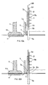
- the reversal operation comprises an ordered sequence of 5 steps ( Figs. 8 to 11 ) that are described hereinafter in detail.
- the frame (3) is lowered to bring the feet (4a) of the legs (4) in contact with the fabric (T), fastening it to the worktop (P); the jaws (5) are dimensioned in such a way that, when the frame (3) is lowered, the base touches the fabric (T) without pressing it.
- two bridges (H) are moved forward under the worktop (P) and touch the lower side of the slot (2) to transversally cover the slot (2) in order to determine the continuity of the worktop (P) on the contact points of the feet (4a), thus ensuring the perfect fastening of the semi-finished product (SE) between the feet (4a) and the worktop (P) during the next step when the edges of the pocket are reversed.
- the reverse means (MR) comprise a pair of rods (6) at a distance lower than the distance of the jaws (5), which rest in idle position under the worktop (P) on the slot (2); each rod (6) has a square truncated base (6a) with sides larger than the distance between the two seams (C1 and C2).
- the truncated base (6a) is joined with the rod (6) by means of a step (6b); a metal rod (7) is helicoidally wound around the rod (6), with the first turn (7a) raised with respect to the connection step (6b) so that a short section (6c) of the rod between the step (6b) and the first turn (7a) and the top section (6d) of the rod (6) over the last turn (7b) of the metal rod (7) remain uncovered.
- a vertical comb (8) is placed on the internal side of each rod (6), with horizontal teeth (8a) laying on a plane passing through the pocket cut (TT).
- the jaws (5) close and slide on the fabric (T) to intercept and partially reverse upwards the transversal sections (Y) of the edge (F), of the reinforcement (R) and of the sampling (M) located in external position with respect to the V-elements (BV) of the pocket cut (TT), as shown in Fig. 9 and Fig. 10A .
- the third step (III) can be divided in five phases (IIIA, IIIB, IIIC, IIID, IIIE), which are hereinafter described in detail with reference to Figs. 10A to 10E , in which for easier reference only one rod (6) with respective jaw (5) is diagrammatically indicated.
- the rods (6) cooperate with the jaws (5) to completely reverse the edge (F), the reinforcement (R) and the facing (M) under the pocket cut (TT).
- the second phase (IIIB) ( Fig. 10B ) starts when the truncated base (6a) is placed under the pocket cut (TT), while the rods (6) continue to descend.
- the third phase (IIIC) ( Fig. 10C ) starts with the interception of the sections (Y) by the helical rod (7) that engages and drags them downwards because of friction, thus bringing them in reverse position under the worktop (P) as desired.
- the jaws (5) cease pushing when the first turn (7a) is brought under the worktop (P).
- the fourth phase (IIID) ends near the top turn (7b) of the helical rod (7), when the jaws (5) cease pushing inwards, and the rods (6) remain in diverged position until the end of their travel.
- the fifth and last phase (IIIE) starts when the turns of the helical rod (7) move beyond the pocket cut (TT), being brought under the worktop (P), with the jaws (5) in close position, without pushing.
- the facing (M) is reversed by the teeth (8a) of the comb(8).
- the fourth step (IV) ( Fig. 11 ) starts when the third descending step (III) is completed and a shutter (9) is lowered to ensure the reversal of the facing (M).
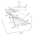
- a bracket (10) with claws (11) (see Fig. 12 ) is lowered to block the fabric (T) and transfer it to the ironing station (SS), while the shutter (9) and the leg-holder frame (3) are raised.
- a tubular blade (12) extends and moves astride the pocket cut, where it remains until the fabric (T) is brought from the overturning station (SR) to the ironing station (SS) in order to maintain the folding obtained in the reversal station (SR).
- bracket (10) and the tubular blade (12) are guided and supported by a track (B2) during their alternate travels.
- the transfer to the ironing station (SS) is carried out by translating the fabric (T) along the axis (X-X) of the pocket cut (TT).
- the edges (F), the reinforcement (R) and the facing (M) slide inside the slot (2) that extends from the reversal station (SR) to the ironing station (SS).
- the slot (2) ends in a rectangular window (13) at the ironing station (SS) (see Figs. 7 and 12 ), which receives the fabric (T) to allow the ironing means (14, 14a) located under and over the worktop (P) in the window (13) to perform their function correctly.
- the first pair of threads (15) is engaged under the fabric (T) (see Fig. 6 ) so that during the translation from the reversal station (SR) and the ironing station (SS) the reversed position of the edges (F), of the reinforcements (R) and of the facing (M) is perfectly maintained.
- the second pair of threads (15a) that is to say the threads located in the window (13), ensures the correct position during ironing, since the threads (15a) cooperate to support the fabric and extend the edges (F), the reinforcements (R) and the facing (M), thus avoiding the creation of folds that may impair ironing.
- the ironing means (14, 14a) comprise a first fixed buffer (14) located immediately under the worktop (P) in the window (13) and a second buffer (14a) located over the first buffer (14) and provided with vertical alternate motion in order to adhere to the first fixed buffer (14).
Landscapes
- Engineering & Computer Science (AREA)
- Textile Engineering (AREA)
- Manufacturing & Machinery (AREA)
- Sewing Machines And Sewing (AREA)
- Manufacture Of Motors, Generators (AREA)
- Details Of Garments (AREA)
- Treatment Of Fiber Materials (AREA)
- Iron Core Of Rotating Electric Machines (AREA)
- Manipulator (AREA)
Claims (8)
- Manipulateur pour renverser le bord des poches effrangées, préposé à intervenir sur un produit semi-fini (SE) formé d'un tissu (T) posé sur un plan de travail (P) et sur lequel tant les coutures (C1 et C2) pour fixer le dit bord (F), que le renforcement (R) et le revers (M) ont été réalisés, étant tous prépliés en forme de "T" renversé, ainsi que la coupure de la poche (TT) réalisée en position parallèle et centrale par rapport aux dites coutures (C1 et C2), caractérisé en ce qu'il comprend :- un poste de renversement (SR), en correspondance duquel une fissure passante (2) est réalisée sur le plan de travail (P) ;- des moyens de prélèvement (1, 1 a, B1) utilisés pour prélever le dit produit semi-fini (SE) dans un poste de prélèvement (SP) réalisé sur le plan (P) et pour transférer le dit produit semi-fini (SE) sur le dit poste de renversement (SR) ;- des moyens d'arrêt (4, 4a) utilisés pour maintenir dans la correcte position le dit produit semi-fini (SE) sur le poste de renversement (SR) ;- des moyens apte au renversement (MR) oeuvrant sur le dit poste de renversement (SR) aux fins de renverser au-dessous du plan (P) les dits bord (F), les dits renforcements (R) et le dit revers (M) ;- une paire opposée de mâchoires (5) oeuvrant au-dessus du plan de travail et en correspondance de la dite fissure (2), ayant la tâche de coopérer avec les dits moyens de renversement (MR), aux fins de faciliter le renversement correct des dits bords (F), des dits renforcements (R) et du dit revers (M) au-dessous du plan (P) ;- un rideau (9) oeuvrant en correspondance de la dite fissure (2) apte à faciliter le renversement correct des dits bords (F), des dits renforcements (R) et du dit revers (M) au-dessous du plan (P);- des actionneurs utilisés pour déplacer le dits moyens de prélèvement (1, 1 a, B1), les dits moyens d'arrêt (4, 4a), les dits moyens de renversement (MR), la dite paire opposée de mâchoires (5), le dit rideau (9) ;- une centrale électronique utilisée pour l'arrêt et le démarrage des dits actionneurs sur la base de signaux reçus par des capteurs prévus à cet effet ou par des interrupteurs de proximité, associés aux composants mobiles du manipulateur.
- Manipulateur selon la revendication 1, caractérisé en ce que les dits moyens de prélèvement (1, 1 a, B1) consistent en un rail (B1) sur lequel glisse une palette allongeable (1) inférieurement à laquelle une fourche (1a) est positionnée, fourche ayant a possibilité de s'abaisser jusqu'à exercer une pression sur le tissu (T), indépendamment l'une (1) de l'autre (1 a).
- Manipulateur selon l'une des revendications précédentes, caractérisé en ce que les dits moyens d'arrêt (4, 4a) comprennent des petits pieds (4a) appliqués à la base des jambes respectives (4) supportées par un châssis portant (3), ayant la possibilité d'accomplir des courses alternées en verticale, châssis qui supporte également les dites mâchoires (5) qui sont couplées au dit châssis (3) afin de pouvoir accomplir de manière simultanée, en horizontale, des courses opposées alternés.
- Manipulateur selon l'une des revendications précédentes, caractérisé en ce que les dits moyens de renversement (MR) comprennent :- une paire de tiges montantes (6), dont l'entraxe est inférieur à celui des mâchoires (5) et qui stationnent, en phase de repos, au-dessous du plan (P), en correspondance de la dite fissure (2), étant prévu que chaque tige montante (6) présente un tronc de base (6a) de section carrée, ayant les côtés de dimensions supérieures à la distance de l'entraxe entre les deux coutures (C1 et C2) et que le dit tronc de base (6a) se raccorde, par le biais d'un échelon (6b), avec la tige (6) surmontante, autour de laquelle s'enroule de manière hélicoïdale un toron métallique (7) dont la spirale de base (7a) résulte soulevée par rapport au dit échelon de raccord (6b), de manière telle qu'entre le dit échelon (6b) et la dite première spirale (7a), un bref segment (6c) de tige reste découvert, exactement comme reste découvert le segment du sommet (6d) de la tige même (6), qui surmonte la spirale la plus élevée (7b) du dit toron (7).- un pivot vertical (8) positionné à l'intérieur de chaque tige (6) et dont les dents horizontales (8a) sont disposées sur un plan vertical passant par l'axe de symétrie longitudinale de la dite fissure (2).
- Manipulateur selon l'une des revendications précédentes, caractérisé en ce que la dite centrale électronique active, dans l'ordre, les déplacements suivants pour la réalisation d'un cycle de travail :- abaissement de la fourche (1a) dans le poste de prélèvement (SP) pour serrer le tissu sur deux points proches de la coupure de la poche (TT) ;- abaissement de la dite palette (1) qui s'allonge afin de bloquer le tissu (T) sur la position désirée ;- coulissement de la fourche (1a) et de la palette (1) le long du dit rail (B1) aux fins de positionner le dit produit semi-fini (SE) au centre du poste de renversement (SR) et au-dessus de la dite fissure (2) ;- descente du châssis (3) avec conséquent serrage du tissu de la part des petits pieds (4a) des jambes (4);- soulèvement de la palette (1a) ;- remontée des moyens de renversement (MR) qui se soulèvent du dessous du plan de travail (P) en passant à travers la dite fissure (2) et à travers la couture de la poche (TT) ;- rapprochement des mâchoires (5) et écartement des dites tiges (6) de manière à ce que les respectifs troncs de base (6a) vont se positionner en butée contre les dites mâchoires ;- descente des moyens de renversement (MR) avec interruption de la poussée d'écartement sur les tiges (6) lorsque le tronc de base (6a) se positionne au-dessous de la fissure (2) et avec cessation de la poussée de rapprochement sur les mâchoires (5) lorsque la première spirale (7a) s'est positionnée au-dessous de la fissure (2) ;- écartement des tiges (6) lorsque les moyens de renversement (MR) ont terminé leur course de descente ;- abaissement du rideau (9) lorsque les moyens de renversement (MR) ont terminé leur course de descente ;- remontée du rideau (9) ;- écartement des mâchoires (5) ;- remontée du châssis (3) ;- abaissement d'une bride (10), équipée inférieurement de griffes (11), oeuvrant dans le poste de renversement (SR) et ayant la tâche de prélever le produit semi-fini (SE) avec les bords renversés ;- coulissement de la fourche (1a) et de la palette (1) le long du rail (B1) de manière à retourner dans le poste de prélèvement (SP).
- Manipulateur selon l'une des revendications précédentes, caractérisé en ce qu'il comprend deux pontets (H) positionnés au-dessous du plan de travail (P) et qui, juste un instant avant l'abaissement du châssis (3), ferment inférieurement la dite fissure (2) en correspondance de deux zones qui coïncident avec les points d'atterrissage sur le plan (P) des petits pieds surmontants (4a), pour ensuite se retirer sur leur position de repos lorsque le châssis (3) se soulève de nouveau.
- Manipulateur selon l'une des revendications précédentes, caractérisé en ce qu'il comprend un rail (B2) de support et de guide pour le coulissement de la dite bride (10) et d'une seconde palette tubulaire (12) ayant la tâche de transférer et d'accompagner le produit semi-fini (SE) en sortie du poste de renversement (SR) jusqu'à un poste de repassage (SS), positionné en aval du dit poste de renversement (SR) et comprenant une ample baie (13), réalisée sur le plan de travail, au-dessus et au-dessous de laquelle sont disposés deux tampons de repassage (14, 14a) ; étant prévu que le dit rail (B2) soit parallèle à l'axe de symétrie longitudinale (X-X) de la dite fissure (2) qui se prolonge jusqu'à déboucher dans la dite baie (13).
- Manipulateur selon la revendication 7, caractérisé en ce qu'il comprend deux paires de fils (15,15a), allongées sur le plan (P), dont la première paire (15) court à l'intérieur de la fissure (2) et de la baie (13), en position parallèle et rapprochée aux bords de la fissure même (2), tandis que les fils de la seconde paire (15a) sont positionnés uniquement en correspondance de la dite baie (13) et la traversent avec un cours divergent, à partir du sommet de raccord (13a) entre la dite fissure (2) et la dite baie (13).
Priority Applications (1)
| Application Number | Priority Date | Filing Date | Title |
|---|---|---|---|
| PL05425089T PL1584249T3 (pl) | 2004-04-08 | 2005-02-21 | Manipulator przeznaczony do odwracania krawędzi rozcinanych kieszeni |
Applications Claiming Priority (2)
| Application Number | Priority Date | Filing Date | Title |
|---|---|---|---|
| ITMC20040056 | 2004-04-08 | ||
| IT000056A ITMC20040056A1 (it) | 2004-04-08 | 2004-04-08 | Manipolatore per il rovesciamento dei filetti delle tasche. |
Publications (2)
| Publication Number | Publication Date |
|---|---|
| EP1584249A1 EP1584249A1 (fr) | 2005-10-12 |
| EP1584249B1 true EP1584249B1 (fr) | 2008-05-28 |
Family
ID=34897775
Family Applications (1)
| Application Number | Title | Priority Date | Filing Date |
|---|---|---|---|
| EP05425089A Expired - Lifetime EP1584249B1 (fr) | 2004-04-08 | 2005-02-21 | Dispositif de retournement des bords d'une poche passepoilée |
Country Status (8)
| Country | Link |
|---|---|
| EP (1) | EP1584249B1 (fr) |
| CN (1) | CN1680655A (fr) |
| AT (1) | ATE396626T1 (fr) |
| DE (1) | DE602005007089D1 (fr) |
| ES (1) | ES2314605T3 (fr) |
| IT (1) | ITMC20040056A1 (fr) |
| PL (1) | PL1584249T3 (fr) |
| PT (1) | PT1584249E (fr) |
Family Cites Families (4)
| Publication number | Priority date | Publication date | Assignee | Title |
|---|---|---|---|---|
| US2529072A (en) * | 1948-05-21 | 1950-11-07 | Reece Corp | Buttonhole sewing machine |
| GB750764A (en) * | 1954-07-07 | 1956-06-20 | Wallace Cranston Fairweather | Device for turning piped garment openings |
| US3335682A (en) * | 1964-08-13 | 1967-08-15 | Anthony G Tucci | Pocket machine |
| JPH07133583A (ja) * | 1993-06-23 | 1995-05-23 | Duerkopp Adler Ag | 生地にパイピングを付けた開口を裁断しかつ裏返しするための装置 |
-
2004
- 2004-04-08 IT IT000056A patent/ITMC20040056A1/it unknown
-
2005
- 2005-02-21 EP EP05425089A patent/EP1584249B1/fr not_active Expired - Lifetime
- 2005-02-21 PL PL05425089T patent/PL1584249T3/pl unknown
- 2005-02-21 DE DE602005007089T patent/DE602005007089D1/de not_active Expired - Fee Related
- 2005-02-21 AT AT05425089T patent/ATE396626T1/de not_active IP Right Cessation
- 2005-02-21 PT PT05425089T patent/PT1584249E/pt unknown
- 2005-02-21 ES ES05425089T patent/ES2314605T3/es not_active Expired - Lifetime
- 2005-04-07 CN CNA2005100632680A patent/CN1680655A/zh active Pending
Also Published As
| Publication number | Publication date |
|---|---|
| ES2314605T3 (es) | 2009-03-16 |
| EP1584249A1 (fr) | 2005-10-12 |
| ATE396626T1 (de) | 2008-06-15 |
| PL1584249T3 (pl) | 2008-10-31 |
| DE602005007089D1 (de) | 2008-07-10 |
| CN1680655A (zh) | 2005-10-12 |
| ITMC20040056A1 (it) | 2004-07-08 |
| PT1584249E (pt) | 2008-09-05 |
Similar Documents
| Publication | Publication Date | Title |
|---|---|---|
| CN104233637B (zh) | 自动缝纫装置及方法 | |
| CN109629215A (zh) | 一种全自动衣服折叠方法及装置 | |
| GB2248544A (en) | Workpiece folding device | |
| KR0185221B1 (ko) | 소매부분 자동봉제장치 | |
| US7174840B2 (en) | Manipulator used to reverse the edges of slash pockets | |
| CN106012328A (zh) | 服装袖侧折叠车缝机构及服装袖侧折叠车缝方法 | |
| EP1584249B1 (fr) | Dispositif de retournement des bords d'une poche passepoilée | |
| JPH0334756B2 (fr) | ||
| WO1981003504A1 (fr) | Systeme de production de feuille avec dispositif d'expansion d'ourlet | |
| US6192816B1 (en) | Method and apparatus for forming and joining hems particularly on tubular trouser legs | |
| KR950032802A (ko) | 웰트형성장치, 그의 제어방법 및 직물가이드 | |
| US3963548A (en) | Apparatus and method of forming hemmed curtains and the like | |
| US3066563A (en) | Apparatus for folding sheet material | |
| CN205848893U (zh) | 全自动折叠拉链机 | |
| CN117845440A (zh) | 翻面装置、缝纫流水线和缝制品的翻面方法 | |
| AU600335B2 (en) | Improvements in or relating to the handling of limp fabric | |
| CN110891463B (zh) | 用于制造张紧床单的方法和设备 | |
| TWI913800B (zh) | 布料摺邊形成機 | |
| US7146755B2 (en) | Process and equipment used to iron the edges of slash pockets | |
| ITTO980299A1 (it) | Macchina da cucire automatica per cucire una patta ad un capo da cuci- re. | |
| JPS6182789A (ja) | タオルヘムの三つ折り方法及びその装置 | |
| CN214422855U (zh) | 三层制衣模板 | |
| EP0215855B1 (fr) | Dispositif de manipulation de tissus souples | |
| EP1358378A1 (fr) | Machine a coudre automatique et procede d'application de la doublure sur des ceintures montees de pantalons | |
| TW202603247A (zh) | 布料摺邊形成機 |
Legal Events
| Date | Code | Title | Description |
|---|---|---|---|
| PUAI | Public reference made under article 153(3) epc to a published international application that has entered the european phase |
Free format text: ORIGINAL CODE: 0009012 |
|
| AK | Designated contracting states |
Kind code of ref document: A1 Designated state(s): AT BE BG CH CY CZ DE DK EE ES FI FR GB GR HU IE IS IT LI LT LU MC NL PL PT RO SE SI SK TR |
|
| AX | Request for extension of the european patent |
Extension state: AL BA HR LV MK YU |
|
| 17P | Request for examination filed |
Effective date: 20060404 |
|
| AKX | Designation fees paid |
Designated state(s): AT BE BG CH CY CZ DE DK EE ES FI FR GB GR HU IE IS IT LI LT LU MC NL PL PT RO SE SI SK TR |
|
| GRAP | Despatch of communication of intention to grant a patent |
Free format text: ORIGINAL CODE: EPIDOSNIGR1 |
|
| GRAS | Grant fee paid |
Free format text: ORIGINAL CODE: EPIDOSNIGR3 |
|
| GRAA | (expected) grant |
Free format text: ORIGINAL CODE: 0009210 |
|
| AK | Designated contracting states |
Kind code of ref document: B1 Designated state(s): AT BE BG CH CY CZ DE DK EE ES FI FR GB GR HU IE IS IT LI LT LU MC NL PL PT RO SE SI SK TR |
|
| REG | Reference to a national code |
Ref country code: GB Ref legal event code: FG4D |
|
| REG | Reference to a national code |
Ref country code: CH Ref legal event code: EP |
|
| REF | Corresponds to: |
Ref document number: 602005007089 Country of ref document: DE Date of ref document: 20080710 Kind code of ref document: P |
|
| REG | Reference to a national code |
Ref country code: IE Ref legal event code: FG4D |
|
| REG | Reference to a national code |
Ref country code: RO Ref legal event code: EPE |
|
| REG | Reference to a national code |
Ref country code: PT Ref legal event code: SC4A Free format text: AVAILABILITY OF NATIONAL TRANSLATION Effective date: 20080826 |
|
| PG25 | Lapsed in a contracting state [announced via postgrant information from national office to epo] |
Ref country code: SI Free format text: LAPSE BECAUSE OF FAILURE TO SUBMIT A TRANSLATION OF THE DESCRIPTION OR TO PAY THE FEE WITHIN THE PRESCRIBED TIME-LIMIT Effective date: 20080528 |
|
| PG25 | Lapsed in a contracting state [announced via postgrant information from national office to epo] |
Ref country code: FI Free format text: LAPSE BECAUSE OF FAILURE TO SUBMIT A TRANSLATION OF THE DESCRIPTION OR TO PAY THE FEE WITHIN THE PRESCRIBED TIME-LIMIT Effective date: 20080528 |
|
| REG | Reference to a national code |
Ref country code: PL Ref legal event code: T3 |
|
| PG25 | Lapsed in a contracting state [announced via postgrant information from national office to epo] |
Ref country code: AT Free format text: LAPSE BECAUSE OF FAILURE TO SUBMIT A TRANSLATION OF THE DESCRIPTION OR TO PAY THE FEE WITHIN THE PRESCRIBED TIME-LIMIT Effective date: 20080528 Ref country code: NL Free format text: LAPSE BECAUSE OF FAILURE TO SUBMIT A TRANSLATION OF THE DESCRIPTION OR TO PAY THE FEE WITHIN THE PRESCRIBED TIME-LIMIT Effective date: 20080528 |
|
| NLV1 | Nl: lapsed or annulled due to failure to fulfill the requirements of art. 29p and 29m of the patents act | ||
| PG25 | Lapsed in a contracting state [announced via postgrant information from national office to epo] |
Ref country code: IS Free format text: LAPSE BECAUSE OF FAILURE TO SUBMIT A TRANSLATION OF THE DESCRIPTION OR TO PAY THE FEE WITHIN THE PRESCRIBED TIME-LIMIT Effective date: 20080928 |
|
| PG25 | Lapsed in a contracting state [announced via postgrant information from national office to epo] |
Ref country code: SE Free format text: LAPSE BECAUSE OF FAILURE TO SUBMIT A TRANSLATION OF THE DESCRIPTION OR TO PAY THE FEE WITHIN THE PRESCRIBED TIME-LIMIT Effective date: 20080828 Ref country code: DK Free format text: LAPSE BECAUSE OF FAILURE TO SUBMIT A TRANSLATION OF THE DESCRIPTION OR TO PAY THE FEE WITHIN THE PRESCRIBED TIME-LIMIT Effective date: 20080528 Ref country code: LT Free format text: LAPSE BECAUSE OF FAILURE TO SUBMIT A TRANSLATION OF THE DESCRIPTION OR TO PAY THE FEE WITHIN THE PRESCRIBED TIME-LIMIT Effective date: 20080528 Ref country code: CZ Free format text: LAPSE BECAUSE OF FAILURE TO SUBMIT A TRANSLATION OF THE DESCRIPTION OR TO PAY THE FEE WITHIN THE PRESCRIBED TIME-LIMIT Effective date: 20080528 |
|
| PG25 | Lapsed in a contracting state [announced via postgrant information from national office to epo] |
Ref country code: SK Free format text: LAPSE BECAUSE OF FAILURE TO SUBMIT A TRANSLATION OF THE DESCRIPTION OR TO PAY THE FEE WITHIN THE PRESCRIBED TIME-LIMIT Effective date: 20080528 Ref country code: BE Free format text: LAPSE BECAUSE OF FAILURE TO SUBMIT A TRANSLATION OF THE DESCRIPTION OR TO PAY THE FEE WITHIN THE PRESCRIBED TIME-LIMIT Effective date: 20080528 |
|
| REG | Reference to a national code |
Ref country code: ES Ref legal event code: FG2A Ref document number: 2314605 Country of ref document: ES Kind code of ref document: T3 |
|
| PLBE | No opposition filed within time limit |
Free format text: ORIGINAL CODE: 0009261 |
|
| STAA | Information on the status of an ep patent application or granted ep patent |
Free format text: STATUS: NO OPPOSITION FILED WITHIN TIME LIMIT |
|
| PG25 | Lapsed in a contracting state [announced via postgrant information from national office to epo] |
Ref country code: BG Free format text: LAPSE BECAUSE OF FAILURE TO SUBMIT A TRANSLATION OF THE DESCRIPTION OR TO PAY THE FEE WITHIN THE PRESCRIBED TIME-LIMIT Effective date: 20080828 Ref country code: EE Free format text: LAPSE BECAUSE OF FAILURE TO SUBMIT A TRANSLATION OF THE DESCRIPTION OR TO PAY THE FEE WITHIN THE PRESCRIBED TIME-LIMIT Effective date: 20080528 |
|
| 26N | No opposition filed |
Effective date: 20090303 |
|
| PG25 | Lapsed in a contracting state [announced via postgrant information from national office to epo] |
Ref country code: MC Free format text: LAPSE BECAUSE OF NON-PAYMENT OF DUE FEES Effective date: 20090228 |
|
| REG | Reference to a national code |
Ref country code: CH Ref legal event code: PL |
|
| GBPC | Gb: european patent ceased through non-payment of renewal fee |
Effective date: 20090221 |
|
| PG25 | Lapsed in a contracting state [announced via postgrant information from national office to epo] |
Ref country code: LI Free format text: LAPSE BECAUSE OF NON-PAYMENT OF DUE FEES Effective date: 20090228 Ref country code: CH Free format text: LAPSE BECAUSE OF NON-PAYMENT OF DUE FEES Effective date: 20090228 |
|
| REG | Reference to a national code |
Ref country code: IE Ref legal event code: MM4A |
|
| REG | Reference to a national code |
Ref country code: FR Ref legal event code: ST Effective date: 20091030 |
|
| PGFP | Annual fee paid to national office [announced via postgrant information from national office to epo] |
Ref country code: DE Payment date: 20090827 Year of fee payment: 5 |
|
| REG | Reference to a national code |
Ref country code: PT Ref legal event code: MM4A Free format text: LAPSE DUE TO NON-PAYMENT OF FEES Effective date: 20091123 |
|
| PG25 | Lapsed in a contracting state [announced via postgrant information from national office to epo] |
Ref country code: IE Free format text: LAPSE BECAUSE OF NON-PAYMENT OF DUE FEES Effective date: 20090221 |
|
| PG25 | Lapsed in a contracting state [announced via postgrant information from national office to epo] |
Ref country code: PT Free format text: LAPSE BECAUSE OF NON-PAYMENT OF DUE FEES Effective date: 20091123 |
|
| REG | Reference to a national code |
Ref country code: ES Ref legal event code: FD2A Effective date: 20090223 |
|
| PG25 | Lapsed in a contracting state [announced via postgrant information from national office to epo] |
Ref country code: GB Free format text: LAPSE BECAUSE OF NON-PAYMENT OF DUE FEES Effective date: 20090221 Ref country code: FR Free format text: LAPSE BECAUSE OF NON-PAYMENT OF DUE FEES Effective date: 20090302 Ref country code: RO Free format text: LAPSE BECAUSE OF NON-PAYMENT OF DUE FEES Effective date: 20080528 |
|
| PG25 | Lapsed in a contracting state [announced via postgrant information from national office to epo] |
Ref country code: ES Free format text: LAPSE BECAUSE OF NON-PAYMENT OF DUE FEES Effective date: 20090223 |
|
| REG | Reference to a national code |
Ref country code: PL Ref legal event code: LAPE |
|
| PG25 | Lapsed in a contracting state [announced via postgrant information from national office to epo] |
Ref country code: PL Free format text: LAPSE BECAUSE OF NON-PAYMENT OF DUE FEES Effective date: 20090221 |
|
| PG25 | Lapsed in a contracting state [announced via postgrant information from national office to epo] |
Ref country code: GR Free format text: LAPSE BECAUSE OF FAILURE TO SUBMIT A TRANSLATION OF THE DESCRIPTION OR TO PAY THE FEE WITHIN THE PRESCRIBED TIME-LIMIT Effective date: 20080829 |
|
| PGFP | Annual fee paid to national office [announced via postgrant information from national office to epo] |
Ref country code: IT Payment date: 20100816 Year of fee payment: 6 |
|
| PG25 | Lapsed in a contracting state [announced via postgrant information from national office to epo] |
Ref country code: DE Free format text: LAPSE BECAUSE OF NON-PAYMENT OF DUE FEES Effective date: 20100901 |
|
| PG25 | Lapsed in a contracting state [announced via postgrant information from national office to epo] |
Ref country code: LU Free format text: LAPSE BECAUSE OF NON-PAYMENT OF DUE FEES Effective date: 20090221 |
|
| PG25 | Lapsed in a contracting state [announced via postgrant information from national office to epo] |
Ref country code: HU Free format text: LAPSE BECAUSE OF FAILURE TO SUBMIT A TRANSLATION OF THE DESCRIPTION OR TO PAY THE FEE WITHIN THE PRESCRIBED TIME-LIMIT Effective date: 20081129 |
|
| PG25 | Lapsed in a contracting state [announced via postgrant information from national office to epo] |
Ref country code: CY Free format text: LAPSE BECAUSE OF FAILURE TO SUBMIT A TRANSLATION OF THE DESCRIPTION OR TO PAY THE FEE WITHIN THE PRESCRIBED TIME-LIMIT Effective date: 20080528 |
|
| PG25 | Lapsed in a contracting state [announced via postgrant information from national office to epo] |
Ref country code: IT Free format text: LAPSE BECAUSE OF NON-PAYMENT OF DUE FEES Effective date: 20110221 |
|
| PG25 | Lapsed in a contracting state [announced via postgrant information from national office to epo] |
Ref country code: TR Free format text: LAPSE BECAUSE OF FAILURE TO SUBMIT A TRANSLATION OF THE DESCRIPTION OR TO PAY THE FEE WITHIN THE PRESCRIBED TIME-LIMIT Effective date: 20080528 |