EP1584221B1 - Linearbeschleuniger für ionenstrahlbeschleunigung - Google Patents
Linearbeschleuniger für ionenstrahlbeschleunigung Download PDFInfo
- Publication number
- EP1584221B1 EP1584221B1 EP03812572A EP03812572A EP1584221B1 EP 1584221 B1 EP1584221 B1 EP 1584221B1 EP 03812572 A EP03812572 A EP 03812572A EP 03812572 A EP03812572 A EP 03812572A EP 1584221 B1 EP1584221 B1 EP 1584221B1
- Authority
- EP
- European Patent Office
- Prior art keywords
- linac
- accelerating
- structures
- ion beam
- fact
- Prior art date
- Legal status (The legal status is an assumption and is not a legal conclusion. Google has not performed a legal analysis and makes no representation as to the accuracy of the status listed.)
- Expired - Lifetime
Links
- 238000010884 ion-beam technique Methods 0.000 title claims abstract description 27
- 230000001133 acceleration Effects 0.000 title claims abstract description 15
- 230000008878 coupling Effects 0.000 claims abstract description 69
- 238000010168 coupling process Methods 0.000 claims abstract description 69
- 238000005859 coupling reaction Methods 0.000 claims abstract description 69
- 239000002245 particle Substances 0.000 claims abstract description 17
- 230000005672 electromagnetic field Effects 0.000 claims abstract description 4
- 230000005684 electric field Effects 0.000 claims description 16
- 238000000034 method Methods 0.000 claims description 10
- 238000011160 research Methods 0.000 claims description 8
- 238000004519 manufacturing process Methods 0.000 claims description 4
- 230000015572 biosynthetic process Effects 0.000 claims 1
- 230000001225 therapeutic effect Effects 0.000 abstract 1
- 150000002500 ions Chemical class 0.000 description 11
- 238000011275 oncology therapy Methods 0.000 description 9
- 230000009467 reduction Effects 0.000 description 8
- 230000008901 benefit Effects 0.000 description 6
- 238000013461 design Methods 0.000 description 6
- 238000010276 construction Methods 0.000 description 5
- 238000003780 insertion Methods 0.000 description 5
- 230000037431 insertion Effects 0.000 description 5
- 230000007423 decrease Effects 0.000 description 4
- 238000013456 study Methods 0.000 description 4
- 238000010586 diagram Methods 0.000 description 3
- 238000012986 modification Methods 0.000 description 3
- 230000004048 modification Effects 0.000 description 3
- 101100240461 Dictyostelium discoideum ngap gene Proteins 0.000 description 2
- 230000005540 biological transmission Effects 0.000 description 2
- 238000011161 development Methods 0.000 description 2
- 238000005516 engineering process Methods 0.000 description 2
- 230000004992 fission Effects 0.000 description 2
- 230000004927 fusion Effects 0.000 description 2
- 238000002347 injection Methods 0.000 description 2
- 239000007924 injection Substances 0.000 description 2
- 238000009434 installation Methods 0.000 description 2
- 239000000243 solution Substances 0.000 description 2
- 238000012360 testing method Methods 0.000 description 2
- KZENBFUSKMWCJF-UHFFFAOYSA-N [5-[5-[5-(hydroxymethyl)-2-thiophenyl]-2-furanyl]-2-thiophenyl]methanol Chemical compound S1C(CO)=CC=C1C1=CC=C(C=2SC(CO)=CC=2)O1 KZENBFUSKMWCJF-UHFFFAOYSA-N 0.000 description 1
- 230000003247 decreasing effect Effects 0.000 description 1
- 230000001419 dependent effect Effects 0.000 description 1
- 230000000694 effects Effects 0.000 description 1
- 230000005284 excitation Effects 0.000 description 1
- 238000002474 experimental method Methods 0.000 description 1
- 238000001914 filtration Methods 0.000 description 1
- 230000001939 inductive effect Effects 0.000 description 1
- RVPVRDXYQKGNMQ-UHFFFAOYSA-N lead(2+) Chemical compound [Pb+2] RVPVRDXYQKGNMQ-UHFFFAOYSA-N 0.000 description 1
- 239000000203 mixture Substances 0.000 description 1
- 230000000737 periodic effect Effects 0.000 description 1
- 238000002661 proton therapy Methods 0.000 description 1
- 238000001959 radiotherapy Methods 0.000 description 1
- 230000006641 stabilisation Effects 0.000 description 1
- 238000011105 stabilization Methods 0.000 description 1
- 230000001360 synchronised effect Effects 0.000 description 1
- 230000036962 time dependent Effects 0.000 description 1
Images


Classifications
-
- H—ELECTRICITY
- H05—ELECTRIC TECHNIQUES NOT OTHERWISE PROVIDED FOR
- H05H—PLASMA TECHNIQUE; PRODUCTION OF ACCELERATED ELECTRICALLY-CHARGED PARTICLES OR OF NEUTRONS; PRODUCTION OR ACCELERATION OF NEUTRAL MOLECULAR OR ATOMIC BEAMS
- H05H9/00—Linear accelerators
-
- H—ELECTRICITY
- H05—ELECTRIC TECHNIQUES NOT OTHERWISE PROVIDED FOR
- H05H—PLASMA TECHNIQUE; PRODUCTION OF ACCELERATED ELECTRICALLY-CHARGED PARTICLES OR OF NEUTRONS; PRODUCTION OR ACCELERATION OF NEUTRAL MOLECULAR OR ATOMIC BEAMS
- H05H7/00—Details of devices of the types covered by groups H05H9/00, H05H11/00, H05H13/00
- H05H7/22—Details of linear accelerators, e.g. drift tubes
Definitions
- the present invention relates to a drift tube linear accelerator (linac) for accelerating ions as a beam, a system comprising such a linac and a method for accelerating an ion beam according to the preambles of claims 1, 8 and 11, respectively.
- the invention also relates to the application fields of the disclosed linac, system and accelerating method.
- particle accelerators are used to accelerate ions (protons and heavier ions) to very high velocities. At high velocities, a large number of such particles form what is called a "beam", and this beam can be used for different purposes, for instance research, medical or industrial applications. Early accelerators' cost and size practically limited the utilisation thereof to research laboratories. Even today, the existing accelerators are often unpractical for many applications making use of ions.
- RF radio frequency
- linacs The technology of radio frequency (RF) linacs is currently used for the acceleration of charged particles from an "ion source" to the desired energy.
- ions prototons and heavier ions
- the energy range covered by linacs is of several tens of kilo-electron-volts per nucleon (keV/u) to hundreds of million-electron-volts per nucleon (MeV/u), i.e. a velocity range from about 0.05 to about 0.8 times that of light.
- keV/u kilo-electron-volts per nucleon
- MeV/u million-electron-volts per nucleon
- Several types of linacs which are maximally efficient in a particular energy sub-range, have been developed. If a large range has to be covered, different linac structures, each optimally chosen in its frequency range, are serially disposed, with a consequent increased complexity and cost of the whole system.
- All linac designs generally consist of evacuated cylindrical type metallic cavities or transmission lines. These structures are filled with electromagnetic energy by RF power generators. The beam passes through the longitudinal axis of the linac and encounters strong RF electric fields that can accelerate the charged particles, if the phase of the RF wave is appropriately synchronised with the arrival of the bunched beam.
- travelling wave structures the accelerator is a transmission line and behaves like a waveguide in which the electromagnetic waves travel along the whole length of the structure. Some power is delivered to the beam, some power is lost due to ohmic losses and the rest is dumped in a matched load.
- standing wave structures the accelerator is a resonant cavity inside which the injected electromagnetic waves establish a time-dependent standing wave pattern, periodic at the resonant frequency.
- ⁇ v / c, where v is the velocity of the particles and c is the velocity of light.
- Standing wave linacs are mainly used for particle velocities less than half the speed of light (low ⁇ linacs). Both standing wave and travelling wave linacs are used for higher velocities (medium ⁇ linacs), with the current trend in favour of the first solution.
- travelling wave linacs predominate (high ⁇ linacs).
- deep cancer therapy with light ion beams requires ⁇ ⁇ 0.6, which is in the range of standing wave linacs.
- the RF electric fields are applied inside evacuated resonant cavities to a linear array of electrodes.
- the spacing between the electrodes is arranged so that the field in an appropriate phase with respect to the beam arrival delivers "useful" power to the particles. The rest of the time, the field is shielded and does not act on the bunched beam.
- the spacing between successive electrodes also takes into account the increase in particle velocity, leading to longer structures for higher velocity beams.
- the RF electric fields in these cavities result from the excitation of resonant electromagnetic cavity modes.
- the field pattern is contained in a cylindrical volume. In such a volume, two family modes can exist:
- H-mode families the insertion of the electrodes drastically re-directs the accelerating field along the beam axis.
- the electric field is better concentrated close to the beam axis, where it is effectively needed. Therefore, H-mode structures are more efficient.
- a parameter commonly used to measure the efficiency of the cavity with respect to power consumption is the "shunt impedance per unit length". This parameter has the dimensions of a resistance per unit length and is independent on the field level and on particle velocity.
- H-mode cavities have quite large effective shunt impedance per unit length, decreasing when the particle velocity increases, while E-mode cavities have the opposite behaviour. Therefore H-mode cavities are more efficient at low velocity, while E-mode cavities are better at high velocity, the crossover usually being placed at around ⁇ ⁇ 0.4.
- the longitudinal dimensions of the accelerating structure are linked to the length travelled by the particles in an RF period, also called the "particle wavelength" or ⁇ , where ⁇ , is the RF wavelength.
- Efficient acceleration occurs when the particles arrive at each accelerating gap with the appropriate RF phase.
- 0-mode the on-axis accelerating field has the same module and sign at each accelerating gap, while in ⁇ -mode the electric field changes sign from one gap to the next.
- the current trend is in favour of the ⁇ -mode, since, for the same ⁇ the effective average field gradient is higher.
- U.S.- A - 5,382,914 discloses a linac for proton therapy, the structure of which is rather conventional and the DTL practically represents the well-known Alvarez structure.
- the 0-mode is used for acceleration in the DTL linac and the latter is considerably long.
- U.S. - A - 5,523,659 relates to a radio frequency focused DTL having a known Alvarez structure with modifications including RF focusing sections of the RFQ type.
- the mechanical construction including the electric focusing is complex.
- the resulting shunt impedance is low and the resulting coupling between longitudinal and transverse planes complicates the beam transport.
- U.S. - A - 5,113,141 discloses a four-fingers RFQ linac structure, which is a H-mode cavity structure, making the attempt to focus and accelerate at the same time low energy beams.
- the efficiency of this kind of focusing rapidly decreases as ⁇ increases.
- the resulting shunt impedance is low and the resulting coupling between longitudinal and transverse planes complicates the beam transport.
- U.S. - A - 4,906,896 relates to a disk and washer linac the structure of which makes use of E-modes. At low ⁇ the shunt impedance is low. The mechanical construction is complicated. The field stability is rather low since it is perturbed by RF resonances close to the working mode.
- the main object of the present invention is to provide a new ion beam accelerator, a system containing such an accelerator and also a method for accelerating ion beams able to satisfy the above-mentioned requirements.
- Another object of the present invention is to use some new as well as some existing components, but exploiting new single and combined functionalities in order that, together, unexpected and surprisingly good results are produced, allowing, among other advantages, an effective reduction in the overall dimensions of the accelerator, which can easily be installed in a clinic or an hospital.
- Still another object of the present invention lies in the proposed modularity, which makes it possible on one hand to produce the ion beam of the required energy, and, on the other hand, to reduce the number of components needed in conventional linacs, thus reducing construction and operational costs.
- An additional object is to be seen in the fact of obtaining high stability for the accelerating field, irrespective of the frequency and length of the resonating structure.
- Another object of the present invention is the increase of the accelerating gradient, and, as a consequence, the considerable reduction of the accelerator length.
- Yet another object of this invention is the consistent reduction in electric power consumption, thus reducing the operational cost of the accelerator, or of the structure or of the overall system including the present invention.
- Still another object of the present invention is the increase of the velocity range up to at least ⁇ ⁇ 0.6 within small dimensions, thus allowing, in case of medical applications, deep cancer therapy.
- Another object of the present invention is the possibility, with the proposed linac, to work also at low frequencies, for instance in the range of about 100 MHz to about 0.8 GHz for high current production for research or other practical applications.
- drift tube linac a drift tube linac, a system containing such a linac and a method for accelerating the ion beam having the characteristics exposed in claims 1, 8 and 11, respectively.
- Figure 1 shows a block diagram of a system or a complete complex K comprising a linac developed according to the present invention and indicated as a whole with 4.
- a conventional ion source 1 injects a collimated ion beam into a conventional "injector" 2, for instance an electrostatic accelerator, or a small cyclotron, or an RFQ.
- the arrow F indicates the beam direction.
- the pre-accelerated beam is then injected into a conventional low energy beam transport section (LEBT) 3, which focuses and steers the beam up to the entry of the accelerator or linac 4 according to the invention.
- Said linac 4 is a kind of D rift T ube L inac (DTL), working at high frequency, for instance for cancer therapy applications.
- Said linac 4 is composed of one or more base modules 7 and/or one or more enlarged modules 7A, described in detail below, and is called C oupled-cavity L inac U Sing Transverse E lectric R adial fields (CLUSTER).
- CLUSTER Transverse E lectric R adial fields
- the accelerating resonant structures 8 are excited, according to the invention, on a H-mode standing wave electromagnetic field pattern, with high working frequency, for instance for cancer therapy.
- several accelerating structures 8 are aligned and coupled together on a modular basis, in order to obtain the required output energy for the CLUSTER 4, foreseen for the beam application.
- Said output beam energy can be modulated by varying the incoming RF power, whereas the output beam intensity can be modulated by adjusting the ion beam injection parameters and dynamics.
- the length of such structures should be as short as possible.
- the use of high working frequencies of about 0.5 GHz to several GHz, e.g. 6-7 GHz, is proposed.
- the present invention solves the problem by creating a sequence of accelerating cavities of moderate length coupled together, with a new coupling modality, as illustrated and explained below. With this new modality, the stability is not only maintained but is also reinforced by the coupling.
- Coupled cavity systems have been proposed or designed but none has considered H-type accelerating structures.
- H-type structures are typically used at low velocity and low frequency.
- the higher the frequency the higher the allowable field, with consequent increase of the energy gain per meter and reduction of the overall accelerator length. This parameter is very critical, for instance in medical applications, where the search for reduction of the overall accelerator length is linked to the reduction of costs and installation space.
- the RF accelerating field causes a radial defocusing effect, particularly important at low energy, which limits the maximum allowable field. Therefore, a certain number of radial focusing actions must be added as well, bringing to an overall increase in the whole accelerator length.
- the transverse focusing is obtained with a well-known technique based on the use of magnetic quadrupoles as focusing elements. The dimensions of said quadrupoles do not scale directly with the frequency. At low frequency the conventional choice is, where possible, the insertion of the quadrupoles inside the accelerating cavities, or, where not possible, the construction of separated cavities alternated by focusing elements.
- the focusing quadrupoles 18 can be located directly inside the coupling structures 9.
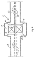
- the coupling structures 9 have two functionalities at the same time: coupling between two accelerating structures 8 and the housing of magnetic quadrupoles 18 for transverse beam focusing.
- Such coupling structure 9 having a diameter of about twice the diameter of the accelerating structures 8, operates functionally like a bridge for the power flow between the structures or accelerating structures 8, and at the same time if necessary houses the quadrupoles 18, as mentioned before, and if necessary presents the connection to the vacuum system 13. Such connection can also be opened elsewhere in the module 7.
- a base module is composed by a middle coupling structure 9 and two accelerating side structures 8, said three structures joined together.
- the coupling with the RF power generator 11 is done, where necessary (e.g. in a single base module), see Figure 2 , through a modified coupling structure 9A.
- Said coupling structure 9A is similar to said coupling structure 9, where structure 9 is split in two parts, called split coupling cells 21, and a third cell, coaxial, called feeder cell 22, is added.
- a possible, but not exclusive configuration is shown in Figure 11 , where a longitudinal 45° bent section comprising the modified coupling structure 9A at the centre and part of two accelerating structures 8 are shown. In this way the ⁇ /2 RF configuration is maintained.
- the two split coupling cells 21 are left unexcited by the field, while the feeder cell 22 is excited. Therefore the power is efficiently injected via a waveguide or a coaxial cable into the feeder cell 22 and passes through the two split coupling cells 21 via two or more slots.
- the length of the so modified coupling structure is such to keep the synchronism with beam acceleration.
- Coupling to the RF power generator according to the invention is therefore mechanically easy to build and has the advantage to avoid any distortion of the field in the accelerating structures 8.
- the proposed coupling system enough space can be allocated in the central part of the coupling structure 9, 9A to insert one or more quadrupoles 18 for the transverse focusing.
- the space needed for the coupling structure is therefore advantageously used also for beam transverse focusing, obtaining in such way the maximum compactness of the whole CLUSTER 4.
- the quadrupoles 18 could also be substituted with other functionally equivalent components, in case placed also out of the coupling structures 9,9A an that, in particular embodiments, said quadrupoles 18 could also be omitted.
- Another teaching of the present invention consists in the combination of the previous teaching and the use of H-modes, intrinsically more efficient.
- a single RF power generator 11 can power a module 7 or 7A of the CLUSTER 4, while, if several associated modules 7 and/or 7A are foreseen, also can be foreseen several single power generators 11, with a single RF output 12 or with multiple, tree-type output 12, where with 12 we define also the RF input entries in the modified coupling structures 9A of modules 7, 7A foreseen.
- each module has a single RF input 11 on a single modified coupling structure 9A.
- the ion beam is accelerated and longitudinally focused at the same time by RF electric fields in the accelerating gaps 20 up to the design energy for the foreseen application, for instance cancer therapy. Transverse focusing is given separately by magnetic fields.
- the CLUSTER output beam is then fired into a high-energy beam transport (HEBT) line 5 that focuses and steers said beam into the utilisation area 6, where it is used, for instance for medical purposes.
- HEBT high-energy beam transport
- the number of required base modules 7 and the composition of the extended modules 7A will depend also on the working frequency, on the maximum power delivered by the RF generators, on the required field level and also on the injection energy of the pre-accelerated beam.
- the modular preferred embodiment allows in any case to minimise the number of RF power generators in the CLUSTER 4, so to reduce as far as possible the cost of the CLUSTER 4 and as a consequence, of the whole system K including CLUSTER 4 according to the invention.
- the cavities in the modules for instance the series of three 8-9, 9A-8 cavities or other series, tuned at the same working frequency, are coupled in order to resonate in the mode ⁇ / 2, with the coupling cavity/ies 9 nominally unexcited or, in case of coupling cavity/ies 9A, only partly excited, where such configuration greatly contributes to the stability of the system.
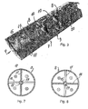
- FIG. 3 A partial tri-dimensional section of the preferred embodiment is shown in Figure 3 . From the Figure can be noticed part of two accelerating structures 8 and a coupling structure 9.
- a series of drift tubes 15, distributed along the longitudinal axis of the CLUSTER 4 is located in the accelerating structures 8.
- the resonant working mode of the accelerating cavities can be classified as an H m10 mode.
- m 2 and the stems 16, 17 are alternately horizontal 16 and vertical 17.
- H-modes have the magnetic field disposed longitudinally along the cavity, while the electric field is radial, except on the axis where the drift tubes 15 introduce a distortion of the electric field along the beam direction F.
- Figures 7 and 8 present respectively a transverse section of the accelerating structure 8 along the sectional line VII-VII and VIII-VIII of Figure 4 and show, according to usual conventions, the direction of the H field.
- the on axis electric field should be approximately constant along the whole structure. This is not the case for the H-modes in a perfect cylindrical cavity, because the magnetic field has a maximum in the centre and a zero at the extremities of the cavity, and this brings to zero the on axis electric field at the extremities.
- Said terminations 10 have the additional purpose to adjust the coupling between accelerating structures 8 and the interposed coupling structure 9, 9A.
- the length and the diameter of said terminations 10 of the accelerating structures 8 are adjusted in such a way to extend the longitudinal H-field lines close to the end caps of said accelerating structure 8.
- the diameter of the coupling structure 9, 9A is about twice the one of the accelerating structure 8, therefore the cylindrical terminations 10 have the shape of an annular chamber of intermediate diameter.
- the thickness of said terminations 10, the thickness between the coupling structure 9, 9A and the terminations 10, and also the number, shape and dimensions of the coupling slots 14, are adjusted, Figures 3 , 4 , 5 , 6 and 11 .
- Said terminations 10 having the shape of annular chambers are open on a circumference corresponding to their inner diameter, while on their outer surface present coupling apertures 14, Figures 6 , 9 and 11 .
- said structures can be described as an oscillating circuit that can be visualised considering for simplicity the capacitive part concentrated in the accelerating gaps 20 created between neighbour drift tubes 15, and the inductive part distributed in the remaining volume between the stems 16, 17 and the internal cavity wall, Figures 7 and 8 .
- the path of the RF current from a drift tube 15 to the neighbour passes back and forth through a horizontal 16 and the vertical neighbours stems 17.
- the working mode of the accelerating structures 8 is the ⁇ -mode, which means that, at a given time in the RF cycle, the on axis electric field direction is reversed passing from one accelerating gap 20 to the next. Effective acceleration is possible at each accelerating gap 20 because the distance between said accelerating gaps 20 is ⁇ / 2.
- the field stability is linked to the spacing between the frequency of the working mode ⁇ 0 and the frequency of the closest (found at higher frequency) longitudinally dependent mode ⁇ 1 .
- a fundamental teaching of the present invention consists in the use of a conventional H-type structure (i.e. a structure typically working at some hundreds of MHz according to conventional structures), that is made to work at high frequency, for instance, as indicated before, for deep cancer therapy.
- the diameter is between about 0.3 and 1 meters and the length can reach a few meters.
- the number of accelerating gaps between successive magnetic lenses is also about 20.
- the maximum number of accelerating gaps 20 per accelerating structure 8 is about 20, the number of accelerating structures 8 to be powered is larger than in a conventional accelerator.
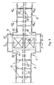
- the basic structure see for example Fig.2 , comprises two accelerating structures and one coupling structure.
- Figure 9 shows a transverse section of the coupling structure 9, at the level of said coupling slots 14, while Figure 10 shows a transverse section of the coupling structure 9 at the level of a magnetic quadrupole 18.
- the coupling structure 9, 9A according to the invention in a preferred embodiment allows the housing of a small quadrupole 18 and ensures at the same time the RF coupling between all the accelerating structures of the same module 7.
- the quadrupoles 18, arranged inside every coupling structure 9, 9A ensure the beam transverse focusing in the FODO lattice configuration.
- commercially available permanent quadrupole magnets 18 of 30 mm longitudinal length and a few mm bore radius can be used. Magnetic gradients of dB/dx ⁇ 500 T/m can be achieved.
- non-permanent quadrupoles 18 or also other functionally equivalent components can be used in CLUSTER 4 applications different from deep cancer therapy, where a lower frequency, for instance of the order of 0.6 GHz can be used.
- the coupling structure 9, 9A does not accelerate the beam and is basically a coaxial resonator oscillating on a TEM standing wave mode. Its length is such to keep the synchronism with beam acceleration.
- the coupling with the accelerating structures 8 is performed through two or more coupling slots 14, four in the example of Figure 9 .
- linacs according to the invention achieve efficiently the scope and advantages indicated and can be advantageously used in a large variety of fields, from the medical one, over which the inventors based the exposed example, to research or many other applications, for instance in high beam current production, in fission and fusion applications, and also where the use of superconducting accelerators is foreseen, and so on.
- An important aspect of the present invention consists in the fact that such a linac or a CLUSTER according to the invention can also efficiently work at lower frequencies than the ones indicated.
- the scope of the present invention includes all CLUSTER structures according to the invention irrespective of the number of the provided base and/or extended modules, wherein the suggested CLUSTER can work at high as well as low frequency, as indicated above.
Landscapes
- Physics & Mathematics (AREA)
- Engineering & Computer Science (AREA)
- Plasma & Fusion (AREA)
- Spectroscopy & Molecular Physics (AREA)
- Particle Accelerators (AREA)
Claims (15)
- Linearbeschleuniger für Ionenstrahlbeschleunigung mit mindestens einem Paar aus einer ersten und einer zweiten Beschleunigungsstruktur (8), die auf derselben Achse ausgerichtet sind, die auf einem elektromagnetischen Feld mit einer stehenden Welle vom H-Typ schwingen und von denen jede eine Mehrzahl von koaxialen Driftröhren (15) aufnimmt, welche durch Bolzen abgestützt und wechselweise beabstandet sind, um jeweils einen Spalt (20) auszubilden, der den Ionenstrahl beschleunigt, wobei ein erster äußerer Endpunkt (8A) der ersten Beschleunigungsstruktur der Eingang des vorbeschleunigten, kollimierten und fokussierten Ionenstrahis ist und ein zweiter äußerer Endpunkt (8B) der Ausgang des Ionenstrahls höherer Energie ist, dadurch gekennzeichet, dass er weiterhin aufweist:i) eine zwischengeordnete Kopplungsstruktur (9) oder eine modifizierte Kopplungsstruktur (9A), die an einen RF-Stromgenerator (11) angeschlossen ist optional mit einem Vakuumsystem (13) verbunden ist und/oder ein oder mehrere Quadrupole (18) umfasst und die als Brücke für den RF-Stromfluss zwischen benachbarten Beschleunigungsstrukturen (8) wirkt, koaxial ist, in einer Resonanzmode mit einer stehenden Welle vom TEM-Typ schwingt, aus zwei koaxialen Zylindern zusammengesetzt ist, deren Länge geeignet ist, um Synchronismus der Beschleunigung zu erhalten, mit der genannten ersten und zweiten Beschleunigungsstruktur (8) an deren jeweiligen inneren Endpunkt (8C) durch ringförmige Abschlüsse (10), welche an beiden Endpunkten der Beschleunigungsstrukturen (8) vorliegen, verbunden ist sowie die Regelung des elektromagnetischen Felds auf der Achse von jedem der Beschleunigungsspalte (20) erlaubt,ii) wobei die Arbeitsfrequenz höher als 100 MHz ist.
- Linearbeschleuniger nach Anspruch 1, dadurch gekennzeichnet, dass innerhalb der Beschleunigungsstrukturen (8) die Driftröhren (15) durch m ≥ 1 dünne radiale Bolzen (16, 17) abgestützt sind, die in Umfangsrichtung gegeneinander um π/m versetzt sind.
- Linearbeschleuniger nach Anspruch 1, dadurch gekennzeichnet, dass die ringförmigen Anschlüsse (10) in der Form einer Ringkammer mit einem inneren Durchmesser, der dem Außendurchmesser der Beschleunigungsstrukturen (8) entspricht, und mit einem Außendurchmesser von ungefähr dem Doppelten des inneren Durchmessers ausgebildet sind, wobei die Anschlüsse (10) in der Form einer Ringkammer an einem dem Innendurchmesser entsprechenden Umfang offen sind, während sie an ihrer äußeren Oberfläche an bestimmten Positionen Kopplungsöffnungen (14) aufweisen.
- Linearbeschleuniger nach Anspruch 1, dadurch gekennzeichnet, dass das Grundmodul (7), das aus der ersten und zweiten Beschleunigungsstruktur (8) und aus der zwischengeordneten, an einen RF-Stromgenerator (11) angeschlossen und optional mit einem oder mehreren Quadrupolen (18) ausgestatteten Kopplungsstruktur (9A) besteht, vorgesehen ist, modular ausgeweitet zu werden, um ausgeweitete Module (7A) auszubilden, die eine immer ungerade Anzahl n von Kopplungsstrukturen (9, 9A), falls erforderlich ausgestattet mit einem oder mehreren Quadrupolen (18), und eine Anzahl N = n + 1 Beschleunigungsstrukturen (8) aufweisen.
- Linearbeschleuniger nach Anspruch 1, dadurch gekennzeichnet, dass die Länge der Driftröhren (15) und der Beschleunigungsspalte (20) ansteigt, so dass der Abstand zwischen den Mittelpunkten von benachbarten Beschleunigungsspalten (20) ungefähr ein ganzzahliges Vielfaches der Teilchenhalbwellenlänge (βλ/2) ist.
- Linearbeschleuniger nach Anspruch 1, dadurch gekennzeichnet, dass die Mehrzahl der Driftröhren (15), die in die Beschleunigungsstrukturen (8) aufgenommen sind, so angeordnet sind, dass sie die Ausbildung der π-Schwingungsmode vorgeben.
- Linearbeschleuniger nach Anspruch 1, dadurch gekennzeichnet, dass jedes Basismodul (7) oder jedes ausgeweitete Modul (7A) eine Reihe von gekoppelten Resonatoren ausbildet, die in der π/2-Mode oszillieren.
- System zur Ionenstrahlbeschleunigung, dadurch gekennzeichnet, dass es aufeinander folgend eine Ionenquelle (1), optional einen Vorbeschleunigerinjektor (2), optional eine Niedrigenergiestrahltransportleitung (3), einen Linearbeschleuniger (4) zur Ionenstrahlbeschleunigung bis zu der Energie, die für eine spezielle Anwendung erforderlich ist, nach einem der Ansprüche 1 bis 7 und weiterhin optional eine Hochenergiestrahltransportleitung (5) und einen Bereich oder eine Vorrichtung (6) aufweist, wo der beschleunigte Strahl verwendet wird.
- Linearbeschleuniger nach Anspruch 1, dadurch gekennzeichnet, dass die Arbeitsfrequenz in dem Bereich von 100 MHz bis 0,8 GHz liegt.
- Linearbeschleuniger nach Anspruch 1, dadurch gekennzeichnet, dass die Arbeitsfrequenz höher als 0,8 GHz liegt.
- Verfahren zum Beschleunigen eines Ionenstrahls in einem Linearbeschleuniger, wobei der Ionenstrahl, der vorbereitend kollimiert, vorbeschleunigt, fokussiert und optional in einer Niedrigenergiestrahltransportleitung (3) geführt wird, in einen Linearbeschleuniger (4) nach einem oder mehreren der Ansprüche 1 bis 10 injiziert wird, in dem:- die Strahlbeschleunigung durch elektrische Felder von Radiofrequenz erhalten wird, deren Feldgröße in allen den Beschleunigungsspalten (20) ist, welche zu demselben in dem Linearbeschleuniger (4) vorgesehenen Modul (7, 7A) gehören, im Wesentlichen konstant ist, wobei das Modul oder die Module (7, 7A) einen einzigen Eingang (12) für den RF-Strom für jedes vorgesehene Modul (7, 7A) aufweisen, wobei der einzelne Eingang (12) für RF-Strom mit einer einzelnen modifizierten Kopplungsstruktur (9A) verbunden ist,- die Querfokussierung mit magnetischen Feldern erreicht wird, die durch Quadrupole (18) generiert werden, welche zwischen zwei oder mehr Beschleunigungsstrukturen (8) vorgesehen sind,- weiterhin an dem Ausgang des Linearbeschleunigers (4) der beschleunigte Ionenstrahl optional in einer Hochenergiestrahltransportleitung (5) in den Bereich oder zu der Vorrichtung (6) geführt wird, wo er zu verwenden ist.
- Verfahren nach Anspruch 11, dadurch gekennzeichnet, dass die Ausgangsstrahlenergie durch Variieren des Eingangs-RF-Stroms moduliert wird und die Intensität des Linearbeschleunigerausgangsstroms durch die Ionenstrahlparameter an dem Linearbeschleunigereingang und durch die Strahldynamik moduliert wird.
- Verwendung eines Linearbeschleunigers oder eines Systems mit einem Linearbeschleuniger nach einem oder mehreren der Ansprüche 1 bis 10 für medizinische Anwendungen.
- Verwendung eines Linearbeschleunigers oder eines Systems mit einem Linearbeschleuniger nach einem oder mehreren der Ansprüche 1 bis 10 für Grundlagen- oder angewandte Forschung und verwandte Anwendungen.
- Verwendung eines Linearbeschleunigers oder eines Systems mit einem Linearbeschleuniger nach einem oder mehreren der Ansprüche 1 bis 10 für die Herstellung eines mittleren Strahlstroms von mehr als 10 µA für Forschung und verwandte Anwendungen.
Applications Claiming Priority (3)
| Application Number | Priority Date | Filing Date | Title |
|---|---|---|---|
| ITMI20022608 | 2002-12-09 | ||
| IT002608A ITMI20022608A1 (it) | 2002-12-09 | 2002-12-09 | Linac a tubi di deriva per l'accelerazione di un fascio di ioni. |
| PCT/EP2003/006254 WO2004054331A1 (en) | 2002-12-09 | 2003-06-13 | Linac for ion beam acceleration |
Publications (2)
| Publication Number | Publication Date |
|---|---|
| EP1584221A1 EP1584221A1 (de) | 2005-10-12 |
| EP1584221B1 true EP1584221B1 (de) | 2012-08-08 |
Family
ID=32448923
Family Applications (1)
| Application Number | Title | Priority Date | Filing Date |
|---|---|---|---|
| EP03812572A Expired - Lifetime EP1584221B1 (de) | 2002-12-09 | 2003-06-13 | Linearbeschleuniger für ionenstrahlbeschleunigung |
Country Status (7)
| Country | Link |
|---|---|
| US (1) | US6888326B2 (de) |
| EP (1) | EP1584221B1 (de) |
| CN (1) | CN100397958C (de) |
| AU (1) | AU2003246428A1 (de) |
| IT (1) | ITMI20022608A1 (de) |
| RU (1) | RU2316157C2 (de) |
| WO (1) | WO2004054331A1 (de) |
Families Citing this family (79)
| Publication number | Priority date | Publication date | Assignee | Title |
|---|---|---|---|---|
| US7791290B2 (en) * | 2005-09-30 | 2010-09-07 | Virgin Islands Microsystems, Inc. | Ultra-small resonating charged particle beam modulator |
| US7626179B2 (en) | 2005-09-30 | 2009-12-01 | Virgin Island Microsystems, Inc. | Electron beam induced resonance |
| US7586097B2 (en) | 2006-01-05 | 2009-09-08 | Virgin Islands Microsystems, Inc. | Switching micro-resonant structures using at least one director |
| ITCO20050007A1 (it) * | 2005-02-02 | 2006-08-03 | Fond Per Adroterapia Oncologia | Sistema di accelerazione di ioni per adroterapia |
| US7957507B2 (en) | 2005-02-28 | 2011-06-07 | Cadman Patrick F | Method and apparatus for modulating a radiation beam |
| US8232535B2 (en) | 2005-05-10 | 2012-07-31 | Tomotherapy Incorporated | System and method of treating a patient with radiation therapy |
| JP2009507524A (ja) | 2005-07-22 | 2009-02-26 | トモセラピー・インコーポレーテッド | 変形マップに制約を課す方法およびそれを実装するためのシステム |
| US8442287B2 (en) | 2005-07-22 | 2013-05-14 | Tomotherapy Incorporated | Method and system for evaluating quality assurance criteria in delivery of a treatment plan |
| CN101500648B (zh) | 2005-07-22 | 2012-07-04 | 断层放疗公司 | 利用剂量体积直方图生成轮廓结构的系统和方法 |
| JP2009502250A (ja) | 2005-07-22 | 2009-01-29 | トモセラピー・インコーポレーテッド | 放射線療法治療計画に関連するデータを処理するための方法およびシステム |
| WO2007014105A2 (en) | 2005-07-22 | 2007-02-01 | Tomotherapy Incorporated | Method and system for adapting a radiation therapy treatment plan based on a biological model |
| CA2616292A1 (en) | 2005-07-22 | 2007-02-01 | Tomotherapy Incorporated | Method and system for evaluating quality assurance criteria in delivery of a treament plan |
| JP2009502257A (ja) | 2005-07-22 | 2009-01-29 | トモセラピー・インコーポレーテッド | デリバーされた線量を評価するための方法およびシステム |
| KR20080039919A (ko) | 2005-07-22 | 2008-05-07 | 토모테라피 인코포레이티드 | 방사선 치료를 받는 환자의 호흡 상태를 검출하는 시스템및 방법 |
| AU2006272742A1 (en) * | 2005-07-22 | 2007-02-01 | Tomotherapy Incorporated | System and method of delivering radiation therapy to a moving region of interest |
| CA2616138A1 (en) * | 2005-07-22 | 2007-02-01 | Tomotherapy Incorporated | System and method of monitoring the operation of a medical device |
| KR20080039920A (ko) | 2005-07-22 | 2008-05-07 | 토모테라피 인코포레이티드 | 방사선 치료 시스템에 의해 부여되는 선량을 평가하는시스템 및 방법 |
| EP1970097A3 (de) | 2005-07-22 | 2009-10-21 | TomoTherapy, Inc. | Verfahren und System zur Vorhersage der Dosierabgabe |
| EP1907057B1 (de) | 2005-07-23 | 2017-01-25 | TomoTherapy, Inc. | Vorrichtung zur strahlungstherapiebildgebung und abgabe mttels koordinierter bewegung von gantry und liege |
| ITCO20050028A1 (it) * | 2005-11-11 | 2007-05-12 | Fond Per Adroterapia Oncologica | Complesso di acceleratori di protoni in particolare per uso medicale |
| US7579609B2 (en) | 2005-12-14 | 2009-08-25 | Virgin Islands Microsystems, Inc. | Coupling light of light emitting resonator to waveguide |
| US7443358B2 (en) | 2006-02-28 | 2008-10-28 | Virgin Island Microsystems, Inc. | Integrated filter in antenna-based detector |
| US7888630B2 (en) * | 2006-04-06 | 2011-02-15 | Wong Alfred Y | Reduced size high frequency quadrupole accelerator for producing a neutralized ion beam of high energy |
| US7876793B2 (en) | 2006-04-26 | 2011-01-25 | Virgin Islands Microsystems, Inc. | Micro free electron laser (FEL) |
| US7646991B2 (en) | 2006-04-26 | 2010-01-12 | Virgin Island Microsystems, Inc. | Selectable frequency EMR emitter |
| US7710040B2 (en) | 2006-05-05 | 2010-05-04 | Virgin Islands Microsystems, Inc. | Single layer construction for ultra small devices |
| US7741934B2 (en) | 2006-05-05 | 2010-06-22 | Virgin Islands Microsystems, Inc. | Coupling a signal through a window |
| US7728397B2 (en) | 2006-05-05 | 2010-06-01 | Virgin Islands Microsystems, Inc. | Coupled nano-resonating energy emitting structures |
| US20070258720A1 (en) * | 2006-05-05 | 2007-11-08 | Virgin Islands Microsystems, Inc. | Inter-chip optical communication |
| US7732786B2 (en) | 2006-05-05 | 2010-06-08 | Virgin Islands Microsystems, Inc. | Coupling energy in a plasmon wave to an electron beam |
| US7656094B2 (en) * | 2006-05-05 | 2010-02-02 | Virgin Islands Microsystems, Inc. | Electron accelerator for ultra-small resonant structures |
| US7728702B2 (en) | 2006-05-05 | 2010-06-01 | Virgin Islands Microsystems, Inc. | Shielding of integrated circuit package with high-permeability magnetic material |
| US7746532B2 (en) | 2006-05-05 | 2010-06-29 | Virgin Island Microsystems, Inc. | Electro-optical switching system and method |
| US7723698B2 (en) | 2006-05-05 | 2010-05-25 | Virgin Islands Microsystems, Inc. | Top metal layer shield for ultra-small resonant structures |
| US7718977B2 (en) * | 2006-05-05 | 2010-05-18 | Virgin Island Microsystems, Inc. | Stray charged particle removal device |
| US8188431B2 (en) | 2006-05-05 | 2012-05-29 | Jonathan Gorrell | Integration of vacuum microelectronic device with integrated circuit |
| US7986113B2 (en) | 2006-05-05 | 2011-07-26 | Virgin Islands Microsystems, Inc. | Selectable frequency light emitter |
| US7679067B2 (en) | 2006-05-26 | 2010-03-16 | Virgin Island Microsystems, Inc. | Receiver array using shared electron beam |
| DE102006027447B4 (de) * | 2006-06-12 | 2010-04-22 | Johann Wolfgang Goethe-Universität Frankfurt am Main | Modularer Linearbeschleuniger |
| US7655934B2 (en) * | 2006-06-28 | 2010-02-02 | Virgin Island Microsystems, Inc. | Data on light bulb |
| US20080128641A1 (en) * | 2006-11-08 | 2008-06-05 | Silicon Genesis Corporation | Apparatus and method for introducing particles using a radio frequency quadrupole linear accelerator for semiconductor materials |
| PL2106678T3 (pl) * | 2006-12-28 | 2010-11-30 | Fond Per Adroterapia Oncologica Tera | System przyspieszania jonów do zastosowań medycznych i/lub innych |
| JP4655046B2 (ja) * | 2007-01-10 | 2011-03-23 | 三菱電機株式会社 | 線形イオン加速器 |
| US7990336B2 (en) | 2007-06-19 | 2011-08-02 | Virgin Islands Microsystems, Inc. | Microwave coupled excitation of solid state resonant arrays |
| US7791053B2 (en) * | 2007-10-10 | 2010-09-07 | Virgin Islands Microsystems, Inc. | Depressed anode with plasmon-enabled devices such as ultra-small resonant structures |
| US20100060208A1 (en) * | 2008-09-09 | 2010-03-11 | Swenson Donald A | Quarter-Wave-Stub Resonant Coupler |
| DE102009032275A1 (de) * | 2009-07-08 | 2011-01-13 | Siemens Aktiengesellschaft | Beschleunigeranlage und Verfahren zur Einstellung einer Partikelenergie |
| FR2949289B1 (fr) * | 2009-08-21 | 2016-05-06 | Thales Sa | Dispositif hyperfrequences d'acceleration d'electrons |
| DE102009048400A1 (de) * | 2009-10-06 | 2011-04-14 | Siemens Aktiengesellschaft | HF-Resonatorkavität und Beschleuniger |
| US9485849B1 (en) * | 2011-10-25 | 2016-11-01 | The Boeing Company | RF particle accelerator structure with fundamental power couplers for ampere class beam current |
| CN102917529B (zh) * | 2012-10-24 | 2016-01-13 | 中国科学院近代物理研究所 | 螺旋型多间隙高频谐振装置及聚束和加速方法 |
| CN103068147A (zh) * | 2012-12-25 | 2013-04-24 | 江苏达胜加速器制造有限公司 | 一种设有导向线圈的加速管 |
| CN103908281B (zh) | 2012-12-31 | 2016-12-28 | 清华大学 | Ct设备及其方法 |
| US9443633B2 (en) | 2013-02-26 | 2016-09-13 | Accuray Incorporated | Electromagnetically actuated multi-leaf collimator |
| DK2825000T3 (en) * | 2013-07-10 | 2016-06-13 | Adam S A | Self-shielded vertical linear proton accelerator for proton therapy |
| ITCO20130036A1 (it) * | 2013-08-22 | 2015-02-23 | Fond Per Adroterapia Oncologi Ca Tera | ¿sistema di acceleratori di ioni per il trattamento della fibrillazione atriale¿ |
| RU2562452C2 (ru) * | 2013-11-19 | 2015-09-10 | Федеральное государственное бюджетное учреждение Национальный исследовательский центр "Курчатовский институт" "Государственный научный центр Российской Федерации - Институт Теоретической и Экспериментальной Физики" | Линейный ускоритель ионов с высокочастотной квадрупольной фокусировкой |
| GB201420936D0 (en) * | 2014-11-25 | 2015-01-07 | Isis Innovation | Radio frequency cavities |
| US10051720B1 (en) * | 2015-07-08 | 2018-08-14 | Los Alamos National Security, Llc | Radio frequency field immersed ultra-low temperature electron source |
| RU2605949C1 (ru) * | 2015-07-14 | 2017-01-10 | Федеральное государственное бюджетное учреждение науки Институт химической кинетики и горения им. В.В. Воеводского Сибирского отделения Российской академии наук (ИХКГ СО РАН) | Ускоряющая структура с параллельной связью |
| CN108369885B (zh) * | 2015-10-20 | 2020-06-23 | 埃因霍温科技大学 | 在透射电子显微镜设备中产生电子束的方法 |
| JP6650146B2 (ja) * | 2015-12-25 | 2020-02-19 | 三菱重工機械システム株式会社 | 加速空洞及び加速器 |
| CN105722297B (zh) * | 2016-03-14 | 2017-08-11 | 中国科学院近代物理研究所 | 混合加速聚焦超导腔 |
| GB201707914D0 (en) * | 2017-05-17 | 2017-06-28 | Univ Of Lancaster | Radio frequency cavities |
| CN107896415A (zh) * | 2017-10-17 | 2018-04-10 | 中国科学院近代物理研究所 | 紧凑型高频电聚焦混合加速腔 |
| CA3089085A1 (en) * | 2018-01-22 | 2019-07-25 | Riken | Accelerator and accelerator system |
| RU2724865C1 (ru) * | 2019-06-26 | 2020-06-25 | Общество с ограниченной ответственностью "Специальное конструкторское бюро "Инновационно-аналитические разработки" | Пучковые устройство, система и комплекс ионно-лучевого наноинвазивного низкоэнергетического воздействия на биологические ткани и агломераты клеток, с функциями впрыска и мониторирования |
| CN112243310B (zh) * | 2019-07-16 | 2022-04-22 | 清华大学 | 多射线源加速器和检查方法 |
| CN111918474B (zh) * | 2020-08-31 | 2024-04-26 | 成都奕康真空电子技术有限责任公司 | 一种局部调频射频电子加速器及加速器调频方法 |
| CN112249288B (zh) * | 2020-09-27 | 2023-09-15 | 李新亚 | 海水电磁加速器 |
| US11818830B2 (en) * | 2021-01-29 | 2023-11-14 | Applied Materials, Inc. | RF quadrupole particle accelerator |
| CN113597079B (zh) * | 2021-07-06 | 2023-08-22 | 哈尔滨工业大学 | 一种用于月球表面充电环境模拟的电子加速器装置 |
| CN114641121B (zh) * | 2022-03-22 | 2023-01-06 | 清华大学 | 场稳定性调谐方法 |
| CN115361770A (zh) * | 2022-08-09 | 2022-11-18 | 杭州嘉辐科技有限公司 | 紧凑型医用重粒子全直线加速器及应用 |
| US12302487B2 (en) * | 2022-09-29 | 2025-05-13 | Applied Materials, Inc. | Particle accelerator having novel electrode configuration for quadrupole focusing |
| CN115623656B (zh) * | 2022-10-31 | 2025-08-29 | 中国科学院上海高等研究院 | 一种基于直线加速段的质子ct增能装置 |
| CN118973073A (zh) * | 2024-10-17 | 2024-11-15 | 华硼中子科技(杭州)有限公司 | 漂移管直线加速器及加速装置 |
| CN119233515B (zh) * | 2024-11-12 | 2025-03-21 | 华硼中子科技(杭州)有限公司 | 一种耦合式直线加速装置的冷却系统 |
| CN119629834B (zh) * | 2024-12-27 | 2025-06-20 | 华硼中子科技(杭州)有限公司 | 加速器电场均匀化调整、调频及谐振腔目标半径获取方法 |
Family Cites Families (14)
| Publication number | Priority date | Publication date | Assignee | Title |
|---|---|---|---|---|
| US3403346A (en) * | 1965-10-20 | 1968-09-24 | Atomic Energy Commission Usa | High energy linear accelerator apparatus |
| GB1311616A (en) * | 1971-04-05 | 1973-03-28 | Bomko V A Revutsky E I Rudiak | Method for the acceleration of ions in linear accelerators and a linear acceleration for the realization of this method |
| US4146817A (en) * | 1977-03-14 | 1979-03-27 | Varian Associates, Inc. | Standing wave linear accelerator and slotted waveguide hybrid junction input coupler |
| SU780822A1 (ru) * | 1979-06-13 | 1981-09-07 | Предприятие П/Я Р-6710 | Ускор юща система линейного ускорител ионов |
| SU890957A1 (ru) * | 1980-07-25 | 1985-08-15 | Предприятие П/Я В-8315 | Ускор юща система линейного ускорител |
| US4712042A (en) * | 1986-02-03 | 1987-12-08 | Accsys Technology, Inc. | Variable frequency RFQ linear accelerator |
| SU1443774A1 (ru) * | 1987-03-16 | 1990-09-23 | Московский Инженерно-Физический Институт | Ускор юща система в виде Н-резонатора |
| US4906896A (en) | 1988-10-03 | 1990-03-06 | Science Applications International Corporation | Disk and washer linac and method of manufacture |
| US5113141A (en) * | 1990-07-18 | 1992-05-12 | Science Applications International Corporation | Four-fingers RFQ linac structure |
| US5382914A (en) | 1992-05-05 | 1995-01-17 | Accsys Technology, Inc. | Proton-beam therapy linac |
| US5523659A (en) | 1994-08-18 | 1996-06-04 | Swenson; Donald A. | Radio frequency focused drift tube linear accelerator |
| US5801488A (en) * | 1996-02-29 | 1998-09-01 | Nissin Electric Co., Ltd. | Variable energy radio-frequency type charged particle accelerator |
| US5825140A (en) * | 1996-02-29 | 1998-10-20 | Nissin Electric Co., Ltd. | Radio-frequency type charged particle accelerator |
| GB2334139B (en) * | 1998-02-05 | 2001-12-19 | Elekta Ab | Linear accelerator |
-
2002
- 2002-12-09 IT IT002608A patent/ITMI20022608A1/it unknown
-
2003
- 2003-06-13 CN CNB038258781A patent/CN100397958C/zh not_active Expired - Fee Related
- 2003-06-13 RU RU2005121525/06A patent/RU2316157C2/ru not_active IP Right Cessation
- 2003-06-13 AU AU2003246428A patent/AU2003246428A1/en not_active Abandoned
- 2003-06-13 EP EP03812572A patent/EP1584221B1/de not_active Expired - Lifetime
- 2003-06-13 WO PCT/EP2003/006254 patent/WO2004054331A1/en not_active Ceased
- 2003-06-24 US US10/602,060 patent/US6888326B2/en not_active Expired - Lifetime
Also Published As
| Publication number | Publication date |
|---|---|
| WO2004054331A1 (en) | 2004-06-24 |
| CN100397958C (zh) | 2008-06-25 |
| RU2316157C2 (ru) | 2008-01-27 |
| EP1584221A1 (de) | 2005-10-12 |
| AU2003246428A1 (en) | 2004-06-30 |
| ITMI20022608A1 (it) | 2004-06-10 |
| US20040108823A1 (en) | 2004-06-10 |
| US6888326B2 (en) | 2005-05-03 |
| CN1736132A (zh) | 2006-02-15 |
| RU2005121525A (ru) | 2006-01-20 |
Similar Documents
| Publication | Publication Date | Title |
|---|---|---|
| EP1584221B1 (de) | Linearbeschleuniger für ionenstrahlbeschleunigung | |
| EP1847160B1 (de) | Ionenbeschleunigungssystem für die hadronentherapie | |
| US11800631B2 (en) | Modified split structure particle accelerators | |
| US6777893B1 (en) | Radio frequency focused interdigital linear accelerator | |
| WO1996006445A1 (en) | Radio frequency focused drift tube linear accelerator | |
| US5014014A (en) | Plane wave transformer linac structure | |
| Gerigk | Cavity types | |
| Vretenar | Linear accelerators | |
| Clemente et al. | Development of room temperature crossbar-H-mode cavities for proton and ion acceleration<? format?> in the low to medium beta range | |
| Kamitsubo | SPring-8 program | |
| Agustsson et al. | Split structure particle accelerators | |
| Ostroumov et al. | An innovative concept for acceleration of low-energy low-charge-state heavy-ion beams | |
| Takata | The Japan Linear Collider | |
| Shen et al. | A pulsed synchronous linear accelerator for low-energy proton | |
| Billen et al. | A versatile, high-power proton linac for accelerator driven transmutation technologies | |
| Yamazaki et al. | Development of the high-intensity proton linac for the Japanese Hadron Project | |
| EP0202097A2 (de) | Linearbeschleuniger geringen Durchmessers mit stehenden Wellen | |
| Schempp | RF quadrupoles as accelerators | |
| Vorogushin et al. | Key systems of an 433 MHz ion linac for applied purposes | |
| Picardi et al. | Preliminary design of a technologically advanced and compact synchrotron for proton therapy | |
| Botman et al. | A microtron accelerator for a free electron laser | |
| Schempp et al. | A Light Ion Four-Rod RFQ Injector | |
| Bomko et al. | DEVELOPMENT OF ALTERNATIVES FOR ACCELERATING STRUC-TURE IN THE RANGE OF INTERMEDIATE PROTON ENERGY | |
| Coleman et al. | Beam transport results on the multi-beam MABE accelerator | |
| Clemente et al. | Beam dynamics investigation of the first tank of a 70 mA CH-DTL proton injector |
Legal Events
| Date | Code | Title | Description |
|---|---|---|---|
| PUAI | Public reference made under article 153(3) epc to a published international application that has entered the european phase |
Free format text: ORIGINAL CODE: 0009012 |
|
| 17P | Request for examination filed |
Effective date: 20050708 |
|
| AK | Designated contracting states |
Kind code of ref document: A1 Designated state(s): AT BE BG CH CY CZ DE DK EE ES FI FR GB GR HU IE IT LI LU MC NL PT RO SE SI SK TR |
|
| AX | Request for extension of the european patent |
Extension state: AL LT LV |
|
| DAX | Request for extension of the european patent (deleted) | ||
| GRAP | Despatch of communication of intention to grant a patent |
Free format text: ORIGINAL CODE: EPIDOSNIGR1 |
|
| GRAS | Grant fee paid |
Free format text: ORIGINAL CODE: EPIDOSNIGR3 |
|
| GRAA | (expected) grant |
Free format text: ORIGINAL CODE: 0009210 |
|
| AK | Designated contracting states |
Kind code of ref document: B1 Designated state(s): AT BE BG CH CY CZ DE DK EE ES FI FR GB GR HU IE IT LI LU MC NL PT RO SE SI SK TR |
|
| REG | Reference to a national code |
Ref country code: GB Ref legal event code: FG4D |
|
| REG | Reference to a national code |
Ref country code: CH Ref legal event code: EP Ref country code: AT Ref legal event code: REF Ref document number: 570302 Country of ref document: AT Kind code of ref document: T Effective date: 20120815 |
|
| REG | Reference to a national code |
Ref country code: IE Ref legal event code: FG4D |
|
| REG | Reference to a national code |
Ref country code: DE Ref legal event code: R096 Ref document number: 60341790 Country of ref document: DE Effective date: 20121011 |
|
| REG | Reference to a national code |
Ref country code: NL Ref legal event code: VDEP Effective date: 20120808 |
|
| REG | Reference to a national code |
Ref country code: AT Ref legal event code: MK05 Ref document number: 570302 Country of ref document: AT Kind code of ref document: T Effective date: 20120808 |
|
| PG25 | Lapsed in a contracting state [announced via postgrant information from national office to epo] |
Ref country code: FI Free format text: LAPSE BECAUSE OF FAILURE TO SUBMIT A TRANSLATION OF THE DESCRIPTION OR TO PAY THE FEE WITHIN THE PRESCRIBED TIME-LIMIT Effective date: 20120808 Ref country code: CY Free format text: LAPSE BECAUSE OF FAILURE TO SUBMIT A TRANSLATION OF THE DESCRIPTION OR TO PAY THE FEE WITHIN THE PRESCRIBED TIME-LIMIT Effective date: 20120808 Ref country code: AT Free format text: LAPSE BECAUSE OF FAILURE TO SUBMIT A TRANSLATION OF THE DESCRIPTION OR TO PAY THE FEE WITHIN THE PRESCRIBED TIME-LIMIT Effective date: 20120808 |
|
| PG25 | Lapsed in a contracting state [announced via postgrant information from national office to epo] |
Ref country code: SE Free format text: LAPSE BECAUSE OF FAILURE TO SUBMIT A TRANSLATION OF THE DESCRIPTION OR TO PAY THE FEE WITHIN THE PRESCRIBED TIME-LIMIT Effective date: 20120808 Ref country code: GR Free format text: LAPSE BECAUSE OF FAILURE TO SUBMIT A TRANSLATION OF THE DESCRIPTION OR TO PAY THE FEE WITHIN THE PRESCRIBED TIME-LIMIT Effective date: 20121109 Ref country code: PT Free format text: LAPSE BECAUSE OF FAILURE TO SUBMIT A TRANSLATION OF THE DESCRIPTION OR TO PAY THE FEE WITHIN THE PRESCRIBED TIME-LIMIT Effective date: 20121210 Ref country code: BE Free format text: LAPSE BECAUSE OF FAILURE TO SUBMIT A TRANSLATION OF THE DESCRIPTION OR TO PAY THE FEE WITHIN THE PRESCRIBED TIME-LIMIT Effective date: 20120808 Ref country code: SI Free format text: LAPSE BECAUSE OF FAILURE TO SUBMIT A TRANSLATION OF THE DESCRIPTION OR TO PAY THE FEE WITHIN THE PRESCRIBED TIME-LIMIT Effective date: 20120808 |
|
| PG25 | Lapsed in a contracting state [announced via postgrant information from national office to epo] |
Ref country code: NL Free format text: LAPSE BECAUSE OF FAILURE TO SUBMIT A TRANSLATION OF THE DESCRIPTION OR TO PAY THE FEE WITHIN THE PRESCRIBED TIME-LIMIT Effective date: 20120808 |
|
| PG25 | Lapsed in a contracting state [announced via postgrant information from national office to epo] |
Ref country code: EE Free format text: LAPSE BECAUSE OF FAILURE TO SUBMIT A TRANSLATION OF THE DESCRIPTION OR TO PAY THE FEE WITHIN THE PRESCRIBED TIME-LIMIT Effective date: 20120808 Ref country code: DK Free format text: LAPSE BECAUSE OF FAILURE TO SUBMIT A TRANSLATION OF THE DESCRIPTION OR TO PAY THE FEE WITHIN THE PRESCRIBED TIME-LIMIT Effective date: 20120808 Ref country code: RO Free format text: LAPSE BECAUSE OF FAILURE TO SUBMIT A TRANSLATION OF THE DESCRIPTION OR TO PAY THE FEE WITHIN THE PRESCRIBED TIME-LIMIT Effective date: 20120808 Ref country code: ES Free format text: LAPSE BECAUSE OF FAILURE TO SUBMIT A TRANSLATION OF THE DESCRIPTION OR TO PAY THE FEE WITHIN THE PRESCRIBED TIME-LIMIT Effective date: 20121119 Ref country code: CZ Free format text: LAPSE BECAUSE OF FAILURE TO SUBMIT A TRANSLATION OF THE DESCRIPTION OR TO PAY THE FEE WITHIN THE PRESCRIBED TIME-LIMIT Effective date: 20120808 |
|
| PG25 | Lapsed in a contracting state [announced via postgrant information from national office to epo] |
Ref country code: IT Free format text: LAPSE BECAUSE OF FAILURE TO SUBMIT A TRANSLATION OF THE DESCRIPTION OR TO PAY THE FEE WITHIN THE PRESCRIBED TIME-LIMIT Effective date: 20120808 Ref country code: SK Free format text: LAPSE BECAUSE OF FAILURE TO SUBMIT A TRANSLATION OF THE DESCRIPTION OR TO PAY THE FEE WITHIN THE PRESCRIBED TIME-LIMIT Effective date: 20120808 |
|
| PLBE | No opposition filed within time limit |
Free format text: ORIGINAL CODE: 0009261 |
|
| STAA | Information on the status of an ep patent application or granted ep patent |
Free format text: STATUS: NO OPPOSITION FILED WITHIN TIME LIMIT |
|
| 26N | No opposition filed |
Effective date: 20130510 |
|
| PG25 | Lapsed in a contracting state [announced via postgrant information from national office to epo] |
Ref country code: BG Free format text: LAPSE BECAUSE OF FAILURE TO SUBMIT A TRANSLATION OF THE DESCRIPTION OR TO PAY THE FEE WITHIN THE PRESCRIBED TIME-LIMIT Effective date: 20121108 |
|
| REG | Reference to a national code |
Ref country code: DE Ref legal event code: R097 Ref document number: 60341790 Country of ref document: DE Effective date: 20130510 |
|
| PG25 | Lapsed in a contracting state [announced via postgrant information from national office to epo] |
Ref country code: MC Free format text: LAPSE BECAUSE OF FAILURE TO SUBMIT A TRANSLATION OF THE DESCRIPTION OR TO PAY THE FEE WITHIN THE PRESCRIBED TIME-LIMIT Effective date: 20120808 |
|
| REG | Reference to a national code |
Ref country code: CH Ref legal event code: PL |
|
| GBPC | Gb: european patent ceased through non-payment of renewal fee |
Effective date: 20130613 |
|
| REG | Reference to a national code |
Ref country code: IE Ref legal event code: MM4A |
|
| REG | Reference to a national code |
Ref country code: DE Ref legal event code: R119 Ref document number: 60341790 Country of ref document: DE Effective date: 20140101 |
|
| REG | Reference to a national code |
Ref country code: FR Ref legal event code: ST Effective date: 20140228 |
|
| PG25 | Lapsed in a contracting state [announced via postgrant information from national office to epo] |
Ref country code: IE Free format text: LAPSE BECAUSE OF NON-PAYMENT OF DUE FEES Effective date: 20130613 Ref country code: GB Free format text: LAPSE BECAUSE OF NON-PAYMENT OF DUE FEES Effective date: 20130613 Ref country code: LI Free format text: LAPSE BECAUSE OF NON-PAYMENT OF DUE FEES Effective date: 20130630 Ref country code: DE Free format text: LAPSE BECAUSE OF NON-PAYMENT OF DUE FEES Effective date: 20140101 Ref country code: CH Free format text: LAPSE BECAUSE OF NON-PAYMENT OF DUE FEES Effective date: 20130630 |
|
| PG25 | Lapsed in a contracting state [announced via postgrant information from national office to epo] |
Ref country code: FR Free format text: LAPSE BECAUSE OF NON-PAYMENT OF DUE FEES Effective date: 20130701 |
|
| PG25 | Lapsed in a contracting state [announced via postgrant information from national office to epo] |
Ref country code: TR Free format text: LAPSE BECAUSE OF FAILURE TO SUBMIT A TRANSLATION OF THE DESCRIPTION OR TO PAY THE FEE WITHIN THE PRESCRIBED TIME-LIMIT Effective date: 20120808 |
|
| PG25 | Lapsed in a contracting state [announced via postgrant information from national office to epo] |
Ref country code: LU Free format text: LAPSE BECAUSE OF NON-PAYMENT OF DUE FEES Effective date: 20130613 Ref country code: HU Free format text: LAPSE BECAUSE OF FAILURE TO SUBMIT A TRANSLATION OF THE DESCRIPTION OR TO PAY THE FEE WITHIN THE PRESCRIBED TIME-LIMIT; INVALID AB INITIO Effective date: 20030613 |