EP1584221B1 - Linac for ion beam acceleration - Google Patents
Linac for ion beam acceleration Download PDFInfo
- Publication number
- EP1584221B1 EP1584221B1 EP03812572A EP03812572A EP1584221B1 EP 1584221 B1 EP1584221 B1 EP 1584221B1 EP 03812572 A EP03812572 A EP 03812572A EP 03812572 A EP03812572 A EP 03812572A EP 1584221 B1 EP1584221 B1 EP 1584221B1
- Authority
- EP
- European Patent Office
- Prior art keywords
- linac
- accelerating
- structures
- ion beam
- fact
- Prior art date
- Legal status (The legal status is an assumption and is not a legal conclusion. Google has not performed a legal analysis and makes no representation as to the accuracy of the status listed.)
- Expired - Lifetime
Links
- 238000010884 ion-beam technique Methods 0.000 title claims abstract description 27
- 230000001133 acceleration Effects 0.000 title claims abstract description 15
- 230000008878 coupling Effects 0.000 claims abstract description 69
- 238000010168 coupling process Methods 0.000 claims abstract description 69
- 238000005859 coupling reaction Methods 0.000 claims abstract description 69
- 239000002245 particle Substances 0.000 claims abstract description 17
- 230000005672 electromagnetic field Effects 0.000 claims abstract description 4
- 230000005684 electric field Effects 0.000 claims description 16
- 238000000034 method Methods 0.000 claims description 10
- 238000011160 research Methods 0.000 claims description 8
- 238000004519 manufacturing process Methods 0.000 claims description 4
- 230000015572 biosynthetic process Effects 0.000 claims 1
- 230000001225 therapeutic effect Effects 0.000 abstract 1
- 150000002500 ions Chemical class 0.000 description 11
- 238000011275 oncology therapy Methods 0.000 description 9
- 230000009467 reduction Effects 0.000 description 8
- 230000008901 benefit Effects 0.000 description 6
- 238000013461 design Methods 0.000 description 6
- 238000010276 construction Methods 0.000 description 5
- 238000003780 insertion Methods 0.000 description 5
- 230000037431 insertion Effects 0.000 description 5
- 230000007423 decrease Effects 0.000 description 4
- 238000013456 study Methods 0.000 description 4
- 238000010586 diagram Methods 0.000 description 3
- 238000012986 modification Methods 0.000 description 3
- 230000004048 modification Effects 0.000 description 3
- 101100240461 Dictyostelium discoideum ngap gene Proteins 0.000 description 2
- 230000005540 biological transmission Effects 0.000 description 2
- 238000011161 development Methods 0.000 description 2
- 238000005516 engineering process Methods 0.000 description 2
- 230000004992 fission Effects 0.000 description 2
- 230000004927 fusion Effects 0.000 description 2
- 238000002347 injection Methods 0.000 description 2
- 239000007924 injection Substances 0.000 description 2
- 238000009434 installation Methods 0.000 description 2
- 239000000243 solution Substances 0.000 description 2
- 238000012360 testing method Methods 0.000 description 2
- KZENBFUSKMWCJF-UHFFFAOYSA-N [5-[5-[5-(hydroxymethyl)-2-thiophenyl]-2-furanyl]-2-thiophenyl]methanol Chemical compound S1C(CO)=CC=C1C1=CC=C(C=2SC(CO)=CC=2)O1 KZENBFUSKMWCJF-UHFFFAOYSA-N 0.000 description 1
- 230000003247 decreasing effect Effects 0.000 description 1
- 230000001419 dependent effect Effects 0.000 description 1
- 230000000694 effects Effects 0.000 description 1
- 230000005284 excitation Effects 0.000 description 1
- 238000002474 experimental method Methods 0.000 description 1
- 238000001914 filtration Methods 0.000 description 1
- 230000001939 inductive effect Effects 0.000 description 1
- RVPVRDXYQKGNMQ-UHFFFAOYSA-N lead(2+) Chemical compound [Pb+2] RVPVRDXYQKGNMQ-UHFFFAOYSA-N 0.000 description 1
- 239000000203 mixture Substances 0.000 description 1
- 230000000737 periodic effect Effects 0.000 description 1
- 238000002661 proton therapy Methods 0.000 description 1
- 238000001959 radiotherapy Methods 0.000 description 1
- 230000006641 stabilisation Effects 0.000 description 1
- 238000011105 stabilization Methods 0.000 description 1
- 230000001360 synchronised effect Effects 0.000 description 1
- 230000036962 time dependent Effects 0.000 description 1
Images


Classifications
-
- H—ELECTRICITY
- H05—ELECTRIC TECHNIQUES NOT OTHERWISE PROVIDED FOR
- H05H—PLASMA TECHNIQUE; PRODUCTION OF ACCELERATED ELECTRICALLY-CHARGED PARTICLES OR OF NEUTRONS; PRODUCTION OR ACCELERATION OF NEUTRAL MOLECULAR OR ATOMIC BEAMS
- H05H9/00—Linear accelerators
-
- H—ELECTRICITY
- H05—ELECTRIC TECHNIQUES NOT OTHERWISE PROVIDED FOR
- H05H—PLASMA TECHNIQUE; PRODUCTION OF ACCELERATED ELECTRICALLY-CHARGED PARTICLES OR OF NEUTRONS; PRODUCTION OR ACCELERATION OF NEUTRAL MOLECULAR OR ATOMIC BEAMS
- H05H7/00—Details of devices of the types covered by groups H05H9/00, H05H11/00, H05H13/00
- H05H7/22—Details of linear accelerators, e.g. drift tubes
Definitions
- the present invention relates to a drift tube linear accelerator (linac) for accelerating ions as a beam, a system comprising such a linac and a method for accelerating an ion beam according to the preambles of claims 1, 8 and 11, respectively.
- the invention also relates to the application fields of the disclosed linac, system and accelerating method.
- particle accelerators are used to accelerate ions (protons and heavier ions) to very high velocities. At high velocities, a large number of such particles form what is called a "beam", and this beam can be used for different purposes, for instance research, medical or industrial applications. Early accelerators' cost and size practically limited the utilisation thereof to research laboratories. Even today, the existing accelerators are often unpractical for many applications making use of ions.
- RF radio frequency
- linacs The technology of radio frequency (RF) linacs is currently used for the acceleration of charged particles from an "ion source" to the desired energy.
- ions prototons and heavier ions
- the energy range covered by linacs is of several tens of kilo-electron-volts per nucleon (keV/u) to hundreds of million-electron-volts per nucleon (MeV/u), i.e. a velocity range from about 0.05 to about 0.8 times that of light.
- keV/u kilo-electron-volts per nucleon
- MeV/u million-electron-volts per nucleon
- Several types of linacs which are maximally efficient in a particular energy sub-range, have been developed. If a large range has to be covered, different linac structures, each optimally chosen in its frequency range, are serially disposed, with a consequent increased complexity and cost of the whole system.
- All linac designs generally consist of evacuated cylindrical type metallic cavities or transmission lines. These structures are filled with electromagnetic energy by RF power generators. The beam passes through the longitudinal axis of the linac and encounters strong RF electric fields that can accelerate the charged particles, if the phase of the RF wave is appropriately synchronised with the arrival of the bunched beam.
- travelling wave structures the accelerator is a transmission line and behaves like a waveguide in which the electromagnetic waves travel along the whole length of the structure. Some power is delivered to the beam, some power is lost due to ohmic losses and the rest is dumped in a matched load.
- standing wave structures the accelerator is a resonant cavity inside which the injected electromagnetic waves establish a time-dependent standing wave pattern, periodic at the resonant frequency.
- ⁇ v / c, where v is the velocity of the particles and c is the velocity of light.
- Standing wave linacs are mainly used for particle velocities less than half the speed of light (low ⁇ linacs). Both standing wave and travelling wave linacs are used for higher velocities (medium ⁇ linacs), with the current trend in favour of the first solution.
- travelling wave linacs predominate (high ⁇ linacs).
- deep cancer therapy with light ion beams requires ⁇ ⁇ 0.6, which is in the range of standing wave linacs.
- the RF electric fields are applied inside evacuated resonant cavities to a linear array of electrodes.
- the spacing between the electrodes is arranged so that the field in an appropriate phase with respect to the beam arrival delivers "useful" power to the particles. The rest of the time, the field is shielded and does not act on the bunched beam.
- the spacing between successive electrodes also takes into account the increase in particle velocity, leading to longer structures for higher velocity beams.
- the RF electric fields in these cavities result from the excitation of resonant electromagnetic cavity modes.
- the field pattern is contained in a cylindrical volume. In such a volume, two family modes can exist:
- H-mode families the insertion of the electrodes drastically re-directs the accelerating field along the beam axis.
- the electric field is better concentrated close to the beam axis, where it is effectively needed. Therefore, H-mode structures are more efficient.
- a parameter commonly used to measure the efficiency of the cavity with respect to power consumption is the "shunt impedance per unit length". This parameter has the dimensions of a resistance per unit length and is independent on the field level and on particle velocity.
- H-mode cavities have quite large effective shunt impedance per unit length, decreasing when the particle velocity increases, while E-mode cavities have the opposite behaviour. Therefore H-mode cavities are more efficient at low velocity, while E-mode cavities are better at high velocity, the crossover usually being placed at around ⁇ ⁇ 0.4.
- the longitudinal dimensions of the accelerating structure are linked to the length travelled by the particles in an RF period, also called the "particle wavelength" or ⁇ , where ⁇ , is the RF wavelength.
- Efficient acceleration occurs when the particles arrive at each accelerating gap with the appropriate RF phase.
- 0-mode the on-axis accelerating field has the same module and sign at each accelerating gap, while in ⁇ -mode the electric field changes sign from one gap to the next.
- the current trend is in favour of the ⁇ -mode, since, for the same ⁇ the effective average field gradient is higher.
- U.S.- A - 5,382,914 discloses a linac for proton therapy, the structure of which is rather conventional and the DTL practically represents the well-known Alvarez structure.
- the 0-mode is used for acceleration in the DTL linac and the latter is considerably long.
- U.S. - A - 5,523,659 relates to a radio frequency focused DTL having a known Alvarez structure with modifications including RF focusing sections of the RFQ type.
- the mechanical construction including the electric focusing is complex.
- the resulting shunt impedance is low and the resulting coupling between longitudinal and transverse planes complicates the beam transport.
- U.S. - A - 5,113,141 discloses a four-fingers RFQ linac structure, which is a H-mode cavity structure, making the attempt to focus and accelerate at the same time low energy beams.
- the efficiency of this kind of focusing rapidly decreases as ⁇ increases.
- the resulting shunt impedance is low and the resulting coupling between longitudinal and transverse planes complicates the beam transport.
- U.S. - A - 4,906,896 relates to a disk and washer linac the structure of which makes use of E-modes. At low ⁇ the shunt impedance is low. The mechanical construction is complicated. The field stability is rather low since it is perturbed by RF resonances close to the working mode.
- the main object of the present invention is to provide a new ion beam accelerator, a system containing such an accelerator and also a method for accelerating ion beams able to satisfy the above-mentioned requirements.
- Another object of the present invention is to use some new as well as some existing components, but exploiting new single and combined functionalities in order that, together, unexpected and surprisingly good results are produced, allowing, among other advantages, an effective reduction in the overall dimensions of the accelerator, which can easily be installed in a clinic or an hospital.
- Still another object of the present invention lies in the proposed modularity, which makes it possible on one hand to produce the ion beam of the required energy, and, on the other hand, to reduce the number of components needed in conventional linacs, thus reducing construction and operational costs.
- An additional object is to be seen in the fact of obtaining high stability for the accelerating field, irrespective of the frequency and length of the resonating structure.
- Another object of the present invention is the increase of the accelerating gradient, and, as a consequence, the considerable reduction of the accelerator length.
- Yet another object of this invention is the consistent reduction in electric power consumption, thus reducing the operational cost of the accelerator, or of the structure or of the overall system including the present invention.
- Still another object of the present invention is the increase of the velocity range up to at least ⁇ ⁇ 0.6 within small dimensions, thus allowing, in case of medical applications, deep cancer therapy.
- Another object of the present invention is the possibility, with the proposed linac, to work also at low frequencies, for instance in the range of about 100 MHz to about 0.8 GHz for high current production for research or other practical applications.
- drift tube linac a drift tube linac, a system containing such a linac and a method for accelerating the ion beam having the characteristics exposed in claims 1, 8 and 11, respectively.
- Figure 1 shows a block diagram of a system or a complete complex K comprising a linac developed according to the present invention and indicated as a whole with 4.
- a conventional ion source 1 injects a collimated ion beam into a conventional "injector" 2, for instance an electrostatic accelerator, or a small cyclotron, or an RFQ.
- the arrow F indicates the beam direction.
- the pre-accelerated beam is then injected into a conventional low energy beam transport section (LEBT) 3, which focuses and steers the beam up to the entry of the accelerator or linac 4 according to the invention.
- Said linac 4 is a kind of D rift T ube L inac (DTL), working at high frequency, for instance for cancer therapy applications.
- Said linac 4 is composed of one or more base modules 7 and/or one or more enlarged modules 7A, described in detail below, and is called C oupled-cavity L inac U Sing Transverse E lectric R adial fields (CLUSTER).
- CLUSTER Transverse E lectric R adial fields
- the accelerating resonant structures 8 are excited, according to the invention, on a H-mode standing wave electromagnetic field pattern, with high working frequency, for instance for cancer therapy.
- several accelerating structures 8 are aligned and coupled together on a modular basis, in order to obtain the required output energy for the CLUSTER 4, foreseen for the beam application.
- Said output beam energy can be modulated by varying the incoming RF power, whereas the output beam intensity can be modulated by adjusting the ion beam injection parameters and dynamics.
- the length of such structures should be as short as possible.
- the use of high working frequencies of about 0.5 GHz to several GHz, e.g. 6-7 GHz, is proposed.
- the present invention solves the problem by creating a sequence of accelerating cavities of moderate length coupled together, with a new coupling modality, as illustrated and explained below. With this new modality, the stability is not only maintained but is also reinforced by the coupling.
- Coupled cavity systems have been proposed or designed but none has considered H-type accelerating structures.
- H-type structures are typically used at low velocity and low frequency.
- the higher the frequency the higher the allowable field, with consequent increase of the energy gain per meter and reduction of the overall accelerator length. This parameter is very critical, for instance in medical applications, where the search for reduction of the overall accelerator length is linked to the reduction of costs and installation space.
- the RF accelerating field causes a radial defocusing effect, particularly important at low energy, which limits the maximum allowable field. Therefore, a certain number of radial focusing actions must be added as well, bringing to an overall increase in the whole accelerator length.
- the transverse focusing is obtained with a well-known technique based on the use of magnetic quadrupoles as focusing elements. The dimensions of said quadrupoles do not scale directly with the frequency. At low frequency the conventional choice is, where possible, the insertion of the quadrupoles inside the accelerating cavities, or, where not possible, the construction of separated cavities alternated by focusing elements.
- the focusing quadrupoles 18 can be located directly inside the coupling structures 9.
- the coupling structures 9 have two functionalities at the same time: coupling between two accelerating structures 8 and the housing of magnetic quadrupoles 18 for transverse beam focusing.
- Such coupling structure 9 having a diameter of about twice the diameter of the accelerating structures 8, operates functionally like a bridge for the power flow between the structures or accelerating structures 8, and at the same time if necessary houses the quadrupoles 18, as mentioned before, and if necessary presents the connection to the vacuum system 13. Such connection can also be opened elsewhere in the module 7.
- a base module is composed by a middle coupling structure 9 and two accelerating side structures 8, said three structures joined together.
- the coupling with the RF power generator 11 is done, where necessary (e.g. in a single base module), see Figure 2 , through a modified coupling structure 9A.
- Said coupling structure 9A is similar to said coupling structure 9, where structure 9 is split in two parts, called split coupling cells 21, and a third cell, coaxial, called feeder cell 22, is added.
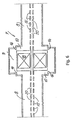
- a possible, but not exclusive configuration is shown in Figure 11 , where a longitudinal 45° bent section comprising the modified coupling structure 9A at the centre and part of two accelerating structures 8 are shown. In this way the ⁇ /2 RF configuration is maintained.
- the two split coupling cells 21 are left unexcited by the field, while the feeder cell 22 is excited. Therefore the power is efficiently injected via a waveguide or a coaxial cable into the feeder cell 22 and passes through the two split coupling cells 21 via two or more slots.
- the length of the so modified coupling structure is such to keep the synchronism with beam acceleration.
- Coupling to the RF power generator according to the invention is therefore mechanically easy to build and has the advantage to avoid any distortion of the field in the accelerating structures 8.
- the proposed coupling system enough space can be allocated in the central part of the coupling structure 9, 9A to insert one or more quadrupoles 18 for the transverse focusing.
- the space needed for the coupling structure is therefore advantageously used also for beam transverse focusing, obtaining in such way the maximum compactness of the whole CLUSTER 4.
- the quadrupoles 18 could also be substituted with other functionally equivalent components, in case placed also out of the coupling structures 9,9A an that, in particular embodiments, said quadrupoles 18 could also be omitted.
- Another teaching of the present invention consists in the combination of the previous teaching and the use of H-modes, intrinsically more efficient.
- a single RF power generator 11 can power a module 7 or 7A of the CLUSTER 4, while, if several associated modules 7 and/or 7A are foreseen, also can be foreseen several single power generators 11, with a single RF output 12 or with multiple, tree-type output 12, where with 12 we define also the RF input entries in the modified coupling structures 9A of modules 7, 7A foreseen.
- each module has a single RF input 11 on a single modified coupling structure 9A.
- the ion beam is accelerated and longitudinally focused at the same time by RF electric fields in the accelerating gaps 20 up to the design energy for the foreseen application, for instance cancer therapy. Transverse focusing is given separately by magnetic fields.
- the CLUSTER output beam is then fired into a high-energy beam transport (HEBT) line 5 that focuses and steers said beam into the utilisation area 6, where it is used, for instance for medical purposes.
- HEBT high-energy beam transport
- the number of required base modules 7 and the composition of the extended modules 7A will depend also on the working frequency, on the maximum power delivered by the RF generators, on the required field level and also on the injection energy of the pre-accelerated beam.
- the modular preferred embodiment allows in any case to minimise the number of RF power generators in the CLUSTER 4, so to reduce as far as possible the cost of the CLUSTER 4 and as a consequence, of the whole system K including CLUSTER 4 according to the invention.
- the cavities in the modules for instance the series of three 8-9, 9A-8 cavities or other series, tuned at the same working frequency, are coupled in order to resonate in the mode ⁇ / 2, with the coupling cavity/ies 9 nominally unexcited or, in case of coupling cavity/ies 9A, only partly excited, where such configuration greatly contributes to the stability of the system.
- FIG. 3 A partial tri-dimensional section of the preferred embodiment is shown in Figure 3 . From the Figure can be noticed part of two accelerating structures 8 and a coupling structure 9.
- a series of drift tubes 15, distributed along the longitudinal axis of the CLUSTER 4 is located in the accelerating structures 8.
- the resonant working mode of the accelerating cavities can be classified as an H m10 mode.
- m 2 and the stems 16, 17 are alternately horizontal 16 and vertical 17.
- H-modes have the magnetic field disposed longitudinally along the cavity, while the electric field is radial, except on the axis where the drift tubes 15 introduce a distortion of the electric field along the beam direction F.
- Figures 7 and 8 present respectively a transverse section of the accelerating structure 8 along the sectional line VII-VII and VIII-VIII of Figure 4 and show, according to usual conventions, the direction of the H field.
- the on axis electric field should be approximately constant along the whole structure. This is not the case for the H-modes in a perfect cylindrical cavity, because the magnetic field has a maximum in the centre and a zero at the extremities of the cavity, and this brings to zero the on axis electric field at the extremities.
- Said terminations 10 have the additional purpose to adjust the coupling between accelerating structures 8 and the interposed coupling structure 9, 9A.
- the length and the diameter of said terminations 10 of the accelerating structures 8 are adjusted in such a way to extend the longitudinal H-field lines close to the end caps of said accelerating structure 8.
- the diameter of the coupling structure 9, 9A is about twice the one of the accelerating structure 8, therefore the cylindrical terminations 10 have the shape of an annular chamber of intermediate diameter.
- the thickness of said terminations 10, the thickness between the coupling structure 9, 9A and the terminations 10, and also the number, shape and dimensions of the coupling slots 14, are adjusted, Figures 3 , 4 , 5 , 6 and 11 .
- Said terminations 10 having the shape of annular chambers are open on a circumference corresponding to their inner diameter, while on their outer surface present coupling apertures 14, Figures 6 , 9 and 11 .
- said structures can be described as an oscillating circuit that can be visualised considering for simplicity the capacitive part concentrated in the accelerating gaps 20 created between neighbour drift tubes 15, and the inductive part distributed in the remaining volume between the stems 16, 17 and the internal cavity wall, Figures 7 and 8 .
- the path of the RF current from a drift tube 15 to the neighbour passes back and forth through a horizontal 16 and the vertical neighbours stems 17.
- the working mode of the accelerating structures 8 is the ⁇ -mode, which means that, at a given time in the RF cycle, the on axis electric field direction is reversed passing from one accelerating gap 20 to the next. Effective acceleration is possible at each accelerating gap 20 because the distance between said accelerating gaps 20 is ⁇ / 2.
- the field stability is linked to the spacing between the frequency of the working mode ⁇ 0 and the frequency of the closest (found at higher frequency) longitudinally dependent mode ⁇ 1 .
- a fundamental teaching of the present invention consists in the use of a conventional H-type structure (i.e. a structure typically working at some hundreds of MHz according to conventional structures), that is made to work at high frequency, for instance, as indicated before, for deep cancer therapy.
- the diameter is between about 0.3 and 1 meters and the length can reach a few meters.
- the number of accelerating gaps between successive magnetic lenses is also about 20.
- the maximum number of accelerating gaps 20 per accelerating structure 8 is about 20, the number of accelerating structures 8 to be powered is larger than in a conventional accelerator.
- the basic structure see for example Fig.2 , comprises two accelerating structures and one coupling structure.
- Figure 9 shows a transverse section of the coupling structure 9, at the level of said coupling slots 14, while Figure 10 shows a transverse section of the coupling structure 9 at the level of a magnetic quadrupole 18.
- the coupling structure 9, 9A according to the invention in a preferred embodiment allows the housing of a small quadrupole 18 and ensures at the same time the RF coupling between all the accelerating structures of the same module 7.
- the quadrupoles 18, arranged inside every coupling structure 9, 9A ensure the beam transverse focusing in the FODO lattice configuration.
- commercially available permanent quadrupole magnets 18 of 30 mm longitudinal length and a few mm bore radius can be used. Magnetic gradients of dB/dx ⁇ 500 T/m can be achieved.
- non-permanent quadrupoles 18 or also other functionally equivalent components can be used in CLUSTER 4 applications different from deep cancer therapy, where a lower frequency, for instance of the order of 0.6 GHz can be used.
- the coupling structure 9, 9A does not accelerate the beam and is basically a coaxial resonator oscillating on a TEM standing wave mode. Its length is such to keep the synchronism with beam acceleration.
- the coupling with the accelerating structures 8 is performed through two or more coupling slots 14, four in the example of Figure 9 .
- linacs according to the invention achieve efficiently the scope and advantages indicated and can be advantageously used in a large variety of fields, from the medical one, over which the inventors based the exposed example, to research or many other applications, for instance in high beam current production, in fission and fusion applications, and also where the use of superconducting accelerators is foreseen, and so on.
- An important aspect of the present invention consists in the fact that such a linac or a CLUSTER according to the invention can also efficiently work at lower frequencies than the ones indicated.
- the scope of the present invention includes all CLUSTER structures according to the invention irrespective of the number of the provided base and/or extended modules, wherein the suggested CLUSTER can work at high as well as low frequency, as indicated above.
Landscapes
- Physics & Mathematics (AREA)
- Engineering & Computer Science (AREA)
- Plasma & Fusion (AREA)
- Spectroscopy & Molecular Physics (AREA)
- Particle Accelerators (AREA)
Abstract
Description
- The present invention relates to a drift tube linear accelerator (linac) for accelerating ions as a beam, a system comprising such a linac and a method for accelerating an ion beam according to the preambles of
claims - It is well known that particle accelerators are used to accelerate ions (protons and heavier ions) to very high velocities. At high velocities, a large number of such particles form what is called a "beam", and this beam can be used for different purposes, for instance research, medical or industrial applications. Early accelerators' cost and size practically limited the utilisation thereof to research laboratories. Even today, the existing accelerators are often unpractical for many applications making use of ions.
- Existing accelerators are of three kinds: cyclotrons, linacs and synchrotrons.
- If the request is for ion beams of large mass-over-charge ratio and/or for the velocity range up to about 0.6 times that of light, conventional cyclotrons are less suited. Compactness, modularity, less complexity and as a result lower cost are the advantages of linacs with respect to synchrotrons.
- The technology of radio frequency (RF) linacs is currently used for the acceleration of charged particles from an "ion source" to the desired energy. For ions (protons and heavier ions), the energy range covered by linacs is of several tens of kilo-electron-volts per nucleon (keV/u) to hundreds of million-electron-volts per nucleon (MeV/u), i.e. a velocity range from about 0.05 to about 0.8 times that of light. Several types of linacs, which are maximally efficient in a particular energy sub-range, have been developed. If a large range has to be covered, different linac structures, each optimally chosen in its frequency range, are serially disposed, with a consequent increased complexity and cost of the whole system.
- All linac designs generally consist of evacuated cylindrical type metallic cavities or transmission lines. These structures are filled with electromagnetic energy by RF power generators. The beam passes through the longitudinal axis of the linac and encounters strong RF electric fields that can accelerate the charged particles, if the phase of the RF wave is appropriately synchronised with the arrival of the bunched beam.
- To date, two kinds of structures have been used: travelling wave and standing wave structures. In travelling wave structures, the accelerator is a transmission line and behaves like a waveguide in which the electromagnetic waves travel along the whole length of the structure. Some power is delivered to the beam, some power is lost due to ohmic losses and the rest is dumped in a matched load. In standing wave structures, the accelerator is a resonant cavity inside which the injected electromagnetic waves establish a time-dependent standing wave pattern, periodic at the resonant frequency.
- It is well known that a parameter commonly employed in this field is β = v / c, where v is the velocity of the particles and c is the velocity of light. Standing wave linacs are mainly used for particle velocities less than half the speed of light (low β linacs). Both standing wave and travelling wave linacs are used for higher velocities (medium β linacs), with the current trend in favour of the first solution. At v ≈ c, travelling wave linacs predominate (high β linacs). It is also known that deep cancer therapy with light ion beams requires β ≤ 0.6, which is in the range of standing wave linacs.
- Moreover, it is known that:
- in the low velocity range (0.01 ≤ β < 0.1), the most commonly used linac structure is the Radio-Frequency Quadrupole (RFQ),
- in the middle velocity range (0.1 ≤ β ≤ 0.4), the most used is the Drift Tube Linac (DTL) structure,
- the Coupled Cavity Linac (CCL) structure is the standing wave structure most used in the high velocity range (0.4 ≤ β < 1).
- In standing wave linacs, the RF electric fields are applied inside evacuated resonant cavities to a linear array of electrodes. The spacing between the electrodes is arranged so that the field in an appropriate phase with respect to the beam arrival delivers "useful" power to the particles. The rest of the time, the field is shielded and does not act on the bunched beam. The spacing between successive electrodes also takes into account the increase in particle velocity, leading to longer structures for higher velocity beams.
- The RF electric fields in these cavities result from the excitation of resonant electromagnetic cavity modes. Normally, the field pattern is contained in a cylindrical volume. In such a volume, two family modes can exist:
- transverse magnetic modes (TM), also called E-modes, where a strong electric field component exists along the beam direction (or, in other words, the magnetic field is transversal to the beam direction),
- transverse electric modes (TE), also called H-modes, where a strong magnetic field component exists along the beam direction (or, in other words, the electric field is transversal to the beam direction). In this latter family, the insertion of the electrodes modifies the field pattern from the just exposed configuration, in such a way that a strong electric field component is always directed along the beam direction, which is the useful direction.
- Experience in cavities development with both types of standing wave patterns has led to understand the different behaviour of cavities using E-modes or H-modes.
- In E-mode families, the insertion of the electrodes does not affect very much the direction of the accelerating field, which is already directed along the beam direction.
- On the contrary, in H-mode families, the insertion of the electrodes drastically re-directs the accelerating field along the beam axis. As a result, in H-mode cavities, the electric field is better concentrated close to the beam axis, where it is effectively needed. Therefore, H-mode structures are more efficient.
- A parameter commonly used to measure the efficiency of the cavity with respect to power consumption is the "shunt impedance per unit length". This parameter has the dimensions of a resistance per unit length and is independent on the field level and on particle velocity.
- Generally speaking, H-mode cavities have quite large effective shunt impedance per unit length, decreasing when the particle velocity increases, while E-mode cavities have the opposite behaviour. Therefore H-mode cavities are more efficient at low velocity, while E-mode cavities are better at high velocity, the crossover usually being placed at around β ≈ 0.4.
- The longitudinal dimensions of the accelerating structure are linked to the length travelled by the particles in an RF period, also called the "particle wavelength" or βλ, where λ, is the RF wavelength. Efficient acceleration occurs when the particles arrive at each accelerating gap with the appropriate RF phase. In an RF linac, two working modes are possible: 0-mode and π-mode. Considering the RF field at a given time, in 0-mode the on-axis accelerating field has the same module and sign at each accelerating gap, while in π-mode the electric field changes sign from one gap to the next. The current trend is in favour of the π-mode, since, for the same βλ the effective average field gradient is higher.
- A more detailed description of the particle accelerators used to date can be found in the references at the end of this description, listed by publication date.
- Finally, it must be pointed out that the field of application has a major impact on the choice between the existing types of proton and ion accelerators of different structural characteristics and functionalities:
- in radiotherapy, the requirement is for extremely precise, very low intensity pencil beams of limited energy and small energy spread. Preferably, they have to be delivered by reasonably small and compact structures to be installed in the limited space available in a hospital environment, while
- in the field of research, the requirement is often for high intensity and high-energy beams for experiments, for instance in high energy physics, or related to nuclear fission, fusion and many other applications.
-
U.S.- A - 5,382,914 discloses a linac for proton therapy, the structure of which is rather conventional and the DTL practically represents the well-known Alvarez structure. The 0-mode is used for acceleration in the DTL linac and the latter is considerably long. -
U.S. - A - 5,523,659 relates to a radio frequency focused DTL having a known Alvarez structure with modifications including RF focusing sections of the RFQ type. The mechanical construction including the electric focusing is complex. The resulting shunt impedance is low and the resulting coupling between longitudinal and transverse planes complicates the beam transport. -
U.S. - A - 5,113,141 discloses a four-fingers RFQ linac structure, which is a H-mode cavity structure, making the attempt to focus and accelerate at the same time low energy beams. The efficiency of this kind of focusing rapidly decreases as β increases. The resulting shunt impedance is low and the resulting coupling between longitudinal and transverse planes complicates the beam transport. -
U.S. - A - 4,906,896 relates to a disk and washer linac the structure of which makes use of E-modes. At low β the shunt impedance is low. The mechanical construction is complicated. The field stability is rather low since it is perturbed by RF resonances close to the working mode. - Accordingly, the main object of the present invention is to provide a new ion beam accelerator, a system containing such an accelerator and also a method for accelerating ion beams able to satisfy the above-mentioned requirements. Another object of the present invention is to use some new as well as some existing components, but exploiting new single and combined functionalities in order that, together, unexpected and surprisingly good results are produced, allowing, among other advantages, an effective reduction in the overall dimensions of the accelerator, which can easily be installed in a clinic or an hospital.
- Still another object of the present invention lies in the proposed modularity, which makes it possible on one hand to produce the ion beam of the required energy, and, on the other hand, to reduce the number of components needed in conventional linacs, thus reducing construction and operational costs.
- An additional object is to be seen in the fact of obtaining high stability for the accelerating field, irrespective of the frequency and length of the resonating structure.
- Another object of the present invention is the increase of the accelerating gradient, and, as a consequence, the considerable reduction of the accelerator length.
- Yet another object of this invention is the consistent reduction in electric power consumption, thus reducing the operational cost of the accelerator, or of the structure or of the overall system including the present invention.
- Still another object of the present invention is the increase of the velocity range up to at least β ≈ 0.6 within small dimensions, thus allowing, in case of medical applications, deep cancer therapy.
- Another object of the present invention is the possibility, with the proposed linac, to work also at low frequencies, for instance in the range of about 100 MHz to about 0.8 GHz for high current production for research or other practical applications.
- These and other objects and advantages are obtained with a drift tube linac, a system containing such a linac and a method for accelerating the ion beam having the characteristics exposed in
claims - Further characteristics, advantages and details of a linac in accordance with the present invention, a system containing such a linac, as well as a ion beam accelerating method in accordance with the present invention will become more apparent from the following disclosure with reference to the accompanying drawings showing preferred inventive embodiments, which are given by way of indicative examples only.
- In the drawings:
-
Figure 1 is a block diagram of a complete system comprising a linac in accordance with the present invention, -
Figure 2 shows three block diagrams respectively of a base module of a CLUSTER (denomination explained hereinafter in the detailed description of preferred embodiments) according to the invention for n = 1, and of two enlarged modules with n = 3 and n = 5, respectively, where n indicates the odd number of coupling structures in the module, -
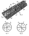
Figure 3 is a perspective view of a longitudinal section of a quarter of the basic structure showing the inner part of two accelerating side structures, of their internal terminations, and of a middle coupling structure. -
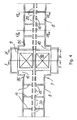
Figure 4 is a partial horizontal longitudinal section of a module showing a middle coupling structure and part of two accelerating side structures, -
Figure 5 is a partial vertical longitudinal section of a module, showing a middle coupling structure and part of two accelerating side structures, -
Figure 6 is a longitudinal section of a module showing a middle coupling structure and part of two accelerating side structures, in a 45° section, -
Figure 7 and inFigure 8 show a section taken along the sectional lines VII-VII and VIII-VIII, respectively, ofFigure 4 , wherein said sections are taken at the centre of the stems and show direction and orientation of the H field, -
Figure 9 and Figure 10 illustrate sections taken along the sectional lines IX-IX and X-X, respectively, ofFigure 4 , -
Figure 11 is a partial longitudinal section of a module, showing a middle coupling structure modified for coupling to RF power feeder and part of two accelerating side structures, in a 45° section. - In the different figures, the same reference number always refers to the same element. Only the parts necessary for the comprehension of the invention have been illustrated. In the following structural, functional and method description, we refer firstly to
Figure 1 , which shows a block diagram of a system or a complete complex K comprising a linac developed according to the present invention and indicated as a whole with 4. - A
conventional ion source 1 injects a collimated ion beam into a conventional "injector" 2, for instance an electrostatic accelerator, or a small cyclotron, or an RFQ. The arrow F indicates the beam direction. The pre-accelerated beam is then injected into a conventional low energy beam transport section (LEBT) 3, which focuses and steers the beam up to the entry of the accelerator or linac 4 according to the invention. Said linac 4 is a kind of Drift Tube Linac (DTL), working at high frequency, for instance for cancer therapy applications. Said linac 4 is composed of one ormore base modules 7 and/or one or moreenlarged modules 7A, described in detail below, and is called Coupled-cavity Linac USing Transverse Electric Radial fields (CLUSTER). As mentioned before, the acceleratingresonant structures 8 are excited, according to the invention, on a H-mode standing wave electromagnetic field pattern, with high working frequency, for instance for cancer therapy. As will be shown and described in more detail below, several acceleratingstructures 8 are aligned and coupled together on a modular basis, in order to obtain the required output energy for the CLUSTER 4, foreseen for the beam application. Said output beam energy can be modulated by varying the incoming RF power, whereas the output beam intensity can be modulated by adjusting the ion beam injection parameters and dynamics. - It should be pointed out that conventional H-type cavities are currently used for the acceleration of low velocity, high intensity and high mass-over-charge ion beams. In such applications, the beam transverse dimensions are rather high (some tens of mm), and therefore the beam hole must also be correspondingly large, at least some tens of mm, a
factor 2/3 is normally accepted between beam diameter and beam hole. As a consequence, the cavities built and working under known concepts are bound to work on a low frequency range, i.e. from about a few MHz (cavities with diameters of about 1 m) up to a few hundreds MHz (cavities with diameters of the order of about 0.3 m). Conversely, in medical applications, since low intensity beams are required, a beam hole of the order of a few mm is large enough. - In order to simplify the installation in hospitals, the length of such structures should be as short as possible. Instead of using mid or low working frequencies, as usually done in the conventional linacs, in the CLUSTER 4, according to the invention, the use of high working frequencies of about 0.5 GHz to several GHz, e.g. 6-7 GHz, is proposed. Today, the progress in mechanical technologies allows the production of such small structures with the required precision.
- It should be also pointed out that the field stability decreases with the increase in frequency and length. This severely limits the development of long conventional accelerating structures. The present invention solves the problem by creating a sequence of accelerating cavities of moderate length coupled together, with a new coupling modality, as illustrated and explained below. With this new modality, the stability is not only maintained but is also reinforced by the coupling.
- Coupled cavity systems have been proposed or designed but none has considered H-type accelerating structures. In the usual techniques H-type structures are typically used at low velocity and low frequency. As indicated before, according to the invention it is on the contrary proposed to use such H-type structures at much higher frequencies. In fact, it is well known that the higher the frequency, the higher the allowable field, with consequent increase of the energy gain per meter and reduction of the overall accelerator length. This parameter is very critical, for instance in medical applications, where the search for reduction of the overall accelerator length is linked to the reduction of costs and installation space.
- However, the RF accelerating field causes a radial defocusing effect, particularly important at low energy, which limits the maximum allowable field. Therefore, a certain number of radial focusing actions must be added as well, bringing to an overall increase in the whole accelerator length. According to the invention, the transverse focusing is obtained with a well-known technique based on the use of magnetic quadrupoles as focusing elements. The dimensions of said quadrupoles do not scale directly with the frequency. At low frequency the conventional choice is, where possible, the insertion of the quadrupoles inside the accelerating cavities, or, where not possible, the construction of separated cavities alternated by focusing elements.
- At high frequency, no space can be allowed for the insertion of the quadrupoles in the accelerating cavities, and the solution of alternate accelerating structures and focusing elements leads to long and unpractical structures.
- On the contrary, as proposed by the present invention, and as can be seen in the figures concerning a preferred embodiment, the focusing
quadrupoles 18 can be located directly inside thecoupling structures 9. In this way, thecoupling structures 9 have two functionalities at the same time: coupling between two acceleratingstructures 8 and the housing ofmagnetic quadrupoles 18 for transverse beam focusing. - According to the present invention a new concept of
coupling structure 9 between acceleratingstructures 8 is proposed.Such coupling structure 9, having a diameter of about twice the diameter of the acceleratingstructures 8, operates functionally like a bridge for the power flow between the structures or acceleratingstructures 8, and at the same time if necessary houses thequadrupoles 18, as mentioned before, and if necessary presents the connection to thevacuum system 13. Such connection can also be opened elsewhere in themodule 7. - Therefore, according to the invention, a base module is composed by a
middle coupling structure 9 and two acceleratingside structures 8, said three structures joined together. - According to the invention, in the illustrated example the coupling with the
RF power generator 11 is done, where necessary (e.g. in a single base module), seeFigure 2 , through a modified coupling structure 9A.Said coupling structure 9A is similar to saidcoupling structure 9, wherestructure 9 is split in two parts, called splitcoupling cells 21, and a third cell, coaxial, calledfeeder cell 22, is added. A possible, but not exclusive configuration is shown inFigure 11 , where a longitudinal 45° bent section comprising the modifiedcoupling structure 9A at the centre and part of two acceleratingstructures 8 are shown. In this way the π/2 RF configuration is maintained. Now the twosplit coupling cells 21 are left unexcited by the field, while thefeeder cell 22 is excited. Therefore the power is efficiently injected via a waveguide or a coaxial cable into thefeeder cell 22 and passes through the twosplit coupling cells 21 via two or more slots. The length of the so modified coupling structure is such to keep the synchronism with beam acceleration. - Coupling to the RF power generator according to the invention is therefore mechanically easy to build and has the advantage to avoid any distortion of the field in the accelerating
structures 8. - According to the invention, with the proposed coupling system enough space can be allocated in the central part of the
coupling structure more quadrupoles 18 for the transverse focusing. The space needed for the coupling structure is therefore advantageously used also for beam transverse focusing, obtaining in such way the maximum compactness of the whole CLUSTER 4. - It is pointed out here that the
quadrupoles 18 could also be substituted with other functionally equivalent components, in case placed also out of thecoupling structures quadrupoles 18 could also be omitted. - With the teaching of the present invention to use high frequencies, it is also possible to achieve a reduction of power consumption. In fact, it is a general rule that, if the geometry of the structure is scaled with the frequency, the effective shunt impedance per unit length increases with the square root of the frequency.
- Another teaching of the present invention consists in the combination of the previous teaching and the use of H-modes, intrinsically more efficient.
- Moreover, according to the invention, in order to produce an ion beam with the required energy for the foreseen application, besides the
base modules 7 also extendedmodules 7A are foreseen, composed by abase module 7 to which are addedmore coupling structures accelerating structures 8, as shown for instance inFigure 2 , where the number n of coupling structures is always an odd number and the number of accelerating structures is N = n + 1. - Therefore, according to the present invention in a simple embodiment a single
RF power generator 11 can power amodule modules 7 and/or 7A are foreseen, also can be foreseen severalsingle power generators 11, with asingle RF output 12 or with multiple, tree-type output 12, where with 12 we define also the RF input entries in the modifiedcoupling structures 9A ofmodules single RF input 11 on a single modifiedcoupling structure 9A. - Back to the figures, in the proposed CLUSTER 4, according to the invention, the ion beam is accelerated and longitudinally focused at the same time by RF electric fields in the accelerating
gaps 20 up to the design energy for the foreseen application, for instance cancer therapy. Transverse focusing is given separately by magnetic fields. The CLUSTER output beam is then fired into a high-energy beam transport (HEBT)line 5 that focuses and steers said beam into the utilisation area 6, where it is used, for instance for medical purposes. - For medical applications it is possible to accelerate the ion beam up to about 4000 MeV (330 MeV/u), which is the present optimal maximum beam energy considered for deep cancer therapy.
- Generally speaking, the number of required
base modules 7 and the composition of theextended modules 7A will depend also on the working frequency, on the maximum power delivered by the RF generators, on the required field level and also on the injection energy of the pre-accelerated beam. According to the present invention, the modular preferred embodiment allows in any case to minimise the number of RF power generators in the CLUSTER 4, so to reduce as far as possible the cost of the CLUSTER 4 and as a consequence, of the whole system K including CLUSTER 4 according to the invention. - It is pointed out that the cavities in the modules, for instance the series of three 8-9, 9A-8 cavities or other series, tuned at the same working frequency, are coupled in order to resonate in the mode π / 2, with the coupling cavity/
ies 9 nominally unexcited or, in case of coupling cavity/ies 9A, only partly excited, where such configuration greatly contributes to the stability of the system. - A partial tri-dimensional section of the preferred embodiment is shown in
Figure 3 . From the Figure can be noticed part of two acceleratingstructures 8 and acoupling structure 9. - From the tri-dimensional picture of
Figure 3 are also shown three different longitudinal sections, and precisely: a horizontal section (Figure 4 ), a vertical section (Figure 5 ), and a 45° bent section (Figure 6 ). - As can be seen from the Figures, a series of
drift tubes 15, distributed along the longitudinal axis of the CLUSTER 4 is located in the acceleratingstructures 8. A number of m thin radial stems 16, 17 with m ≥ 1, support, from the internal surface of the tank wall of the acceleratingstructures 8, each saiddrift tube 15. The resonant working mode of the accelerating cavities can be classified as an Hm10 mode. In the shown preferred embodiment m = 2 and the stems 16, 17 are alternately horizontal 16 and vertical 17. - In other configurations with m > 2 the neighbour stems 16, 17 are reciprocally rotated by π / m.
- H-modes have the magnetic field disposed longitudinally along the cavity, while the electric field is radial, except on the axis where the
drift tubes 15 introduce a distortion of the electric field along the beam direction F.Figures 7 and 8 present respectively a transverse section of the acceleratingstructure 8 along the sectional line VII-VII and VIII-VIII ofFigure 4 and show, according to usual conventions, the direction of the H field. - It is well known that, for an efficient acceleration, the on axis electric field should be approximately constant along the whole structure. This is not the case for the H-modes in a perfect cylindrical cavity, because the magnetic field has a maximum in the centre and a zero at the extremities of the cavity, and this brings to zero the on axis electric field at the extremities.
- Some mechanical and structural modifications have therefore been added according to the invention at the terminations of the accelerating
structures 8, and also at thecoupling terminations 10 between acceleratingstructures 8 and interposedcoupling structure gap 20. Saidterminations 10 have the additional purpose to adjust the coupling between acceleratingstructures 8 and the interposedcoupling structure terminations 10 of the acceleratingstructures 8 are adjusted in such a way to extend the longitudinal H-field lines close to the end caps of said acceleratingstructure 8. The diameter of thecoupling structure structure 8, therefore thecylindrical terminations 10 have the shape of an annular chamber of intermediate diameter. To the second purpose, the thickness of saidterminations 10, the thickness between thecoupling structure terminations 10, and also the number, shape and dimensions of thecoupling slots 14, are adjusted,Figures 3 ,4 ,5 ,6 and11 . - Said
terminations 10 having the shape of annular chambers are open on a circumference corresponding to their inner diameter, while on their outer surfacepresent coupling apertures 14,Figures 6 ,9 and11 . - Back to the accelerating
structures 8, said structures can be described as an oscillating circuit that can be visualised considering for simplicity the capacitive part concentrated in the acceleratinggaps 20 created betweenneighbour drift tubes 15, and the inductive part distributed in the remaining volume between the stems 16, 17 and the internal cavity wall,Figures 7 and 8 . In an RF period, the path of the RF current from adrift tube 15 to the neighbour passes back and forth through a horizontal 16 and the vertical neighbours stems 17. - The working mode of the accelerating
structures 8 is the π-mode, which means that, at a given time in the RF cycle, the on axis electric field direction is reversed passing from one acceleratinggap 20 to the next. Effective acceleration is possible at each acceleratinggap 20 because the distance between said acceleratinggaps 20 is βλ / 2. The field stability is linked to the spacing between the frequency of the working mode ω0 and the frequency of the closest (found at higher frequency) longitudinally dependent mode ω1. The dependence of ω1 from the number of accelerating gaps "ngap" per accelerating structure is described by the formula:
- Since the ratio ω1 /ω0 must not be less than a few per mil, a maximum of about 20 accelerating
gaps 20 per acceleratingstructure 8 has been accepted. As already mentioned, a fundamental teaching of the present invention consists in the use of a conventional H-type structure (i.e. a structure typically working at some hundreds of MHz according to conventional structures), that is made to work at high frequency, for instance, as indicated before, for deep cancer therapy. - In conventional H-mode cavities the diameter is between about 0.3 and 1 meters and the length can reach a few meters. The number of accelerating gaps between successive magnetic lenses is also about 20.
- On the contrary, according to the present invention, and as can be found from the following Table 1, the length of the accelerating
structures 8 does not exceed about 350 mm, reached at about β = 0.6, and the diameter does not exceed about 100 mm. Since the acceleratinggap length 20 decreases linearly with the frequency, while the maximum field that can be applied (according to a criterion established experimentally by Kilpatrick in 1953) increases only with about the square root of the frequency, the length of the structure for the same energy gain decreases roughly as the square root of the frequency, but moreaccelerating gaps 20 are required. - Since the maximum number of accelerating
gaps 20 per acceleratingstructure 8 is about 20, the number of acceleratingstructures 8 to be powered is larger than in a conventional accelerator. - Moreover, direct coupling of a power line to such a small diameter structure would be extremely difficult to design, since it would be impossible to avoid severe distortions in the accelerating field. The small transverse dimensions also avoid the possibility to insert magnetic quadrupoles as focusing lenses inside the structure, as often done in the conventional cavities working at low frequency.
- As explained before, these problems are efficiently solved by the novel technical and structural design of the CLUSTER 4, comprising
base modules 7 andextended modules 7A. The basic structure, see for exampleFig.2 , comprises two accelerating structures and one coupling structure. -
Figure 9 shows a transverse section of thecoupling structure 9, at the level of saidcoupling slots 14, whileFigure 10 shows a transverse section of thecoupling structure 9 at the level of amagnetic quadrupole 18. As already mentioned, thecoupling structure small quadrupole 18 and ensures at the same time the RF coupling between all the accelerating structures of thesame module 7. - In the presented embodiment, according to the invention, the
quadrupoles 18, arranged inside everycoupling structure permanent quadrupole magnets 18 of 30 mm longitudinal length and a few mm bore radius can be used. Magnetic gradients of dB/dx ≈ 500 T/m can be achieved. - Alternatively
non-permanent quadrupoles 18 or also other functionally equivalent components can be used in CLUSTER 4 applications different from deep cancer therapy, where a lower frequency, for instance of the order of 0.6 GHz can be used. - The
coupling structure structures 8 is performed through two ormore coupling slots 14, four in the example ofFigure 9 . - Table 1 summarizes three examples of possible CLUSTER 4 modules, working at different frequencies: 1.5,3.0 and 6.0 GHz. In these examples 12C6+ (Q = 6, A = 12) is the accelerated particle.
Table 1 Examples of possible CLUSTER modules to accelerate 12C6+ (Q = 6, A = 12). EXAMPLES OF POSSIBLE CLUSTER MODULES 1 2 3 Frequency [MHz] 1500 3000 6000 Q (ion charge) 6 6 6 A (ion mass) 12 12 12 Input Energy [MeV] (βinput= v/c ~ 0.25) 360 360 360 Output Energy [MeV] (0.27 ≤ βoutput = v/c ≤ 0.28) 472 442 418 Number of accelerating structures per module N 4 4 4 Accelerating structure length (average) [mm] 370 180 90 Accelerating structure diameter [mm] 90 42 21 Coupling structure length [mm]* ~35 ~35 ~35 Coupling structure diameter [mm] 180 80 50 Beam hole diameter [mm] 10.0 5.0 2.5 Overall length (module with 4 accelerating structures) [mm] 1585 825 465 Shunt impedance Z[MΩ/m] ~100 ~140 ~200 Average on axis field E0[MV/m] 16.1 23.9 34.5 Maximum surface field Emax [MV/m] (≈2.5 x EKilpatrick) 87.5 117.5 162.5 Peak power (per module of 4 accelerating structures) [MW] 5.5 3.43 2.5 Magnetic quadrupole length [mm] 30 30 30 Magnetic quadrupole gradient B' [T/m] (FODO lattice) 210 355 475 Phase advance per period σ [deg] 80 74 50 Beam minimum envelope βmin [mm/mrad] 0.3 0.2 0.2 Beam maximum envelope βmax [mm/mrad] 1.6 0.9 0.6 * Tuned to be adapted to the quadrupole length. - From the above structural and functional description it is inferable that linacs according to the invention achieve efficiently the scope and advantages indicated and can be advantageously used in a large variety of fields, from the medical one, over which the inventors based the exposed example, to research or many other applications, for instance in high beam current production, in fission and fusion applications, and also where the use of superconducting accelerators is foreseen, and so on.
- An important aspect of the present invention consists in the fact that such a linac or a CLUSTER according to the invention can also efficiently work at lower frequencies than the ones indicated. In fact, by appropriately reduction of the working frequency, for instance working with frequency of the order of 100 MHz to 0.5 GHz, it is possible to obtain higher currents, as required in many research fields. Therefore, the scope of the present invention includes all CLUSTER structures according to the invention irrespective of the number of the provided base and/or extended modules, wherein the suggested CLUSTER can work at high as well as low frequency, as indicated above.
- Those skilled in the field may introduce technically and functionally equivalent modifications in the design of linacs and CLUSTER according to the invention for various applications without departing from the scope of the present invention as defined in the appended claims.
-
- P.M. Lapostolle, "Introduction à la Théorie des Accélérateurs Lineaires", CERN 87-09 Division du Synchrotron à Protons, Juillet 1987.
- T. P. Wangler, "Introduction to Linear Accelerators", Los Alamos National Laboratories Report LA-UR-93-805, April 1993.
- U. Ratzinger, "Effiziente Hochfrequenz-Linearbeschleuniger für leichte und schwere Ionen", Habilitationsschrift, Fachbereich Physik der Johann Wolfgang Goethe Universität, Frankfurt am Main, Juli 1998.
- Inventors' past contributions to the field are listed below, ordered by publication date:
- U. Amaldi, A Possible Scheme to Obtain e-e- and e+e-Collisions at Energies of Hundreds of GeV, Phys. Lett. Vol. 61B, Nr.3, pp.313-5, March 1976.
- U. Amaldi, M. Grandolfo, and L. Picardi editors, "The RITA Network and the Design of Compact Proton Accelerators", INFN-LNF Frascati, Italy, August 1996 (ISBN 88-86409-08-7).
- M. Crescenti and 2 co-authors, "Commissioning and Experience in Stripping, Filtering and Measuring the 4.2 MeV/u Lead Ion Beam at CERN Linac3", Linac96, Geneva, Switzerland, August 1996.
- R. Zennaro and 2 co-authors, "Equivalent Lumped Circuit Study for the Field Stabilization of a Long 4-Vane RFQ", Linac98, Chicago August 1998.
- M. Crescenti and 8 co-authors, "Proton-Ion Medical Machine Study (PIMMS) PART I", CERN/PS 99-010 (DI), Geneva, Switzerland, March 1999.
- U.Amaldi, R. Zennaro and 14 co-authors, "Study, Construction and Test of a 3 GHz Proton Linac Booster (LIBO) for Cancer Therapy", EPAC2000, Vienna, Austria, June 2000.
- U. Amaldi, R. Zennaro and 13 co-authors, "Successful High Power Test of a Proton Linac Booster (LIBO) Prototype for Hadrontherapy", PAC2000, Chicago, August 2000.
- M. Crescenti and 13 co-authors, "Proton-Ion Medical Machine Study (PIMMS) PART II", CERN/PS 2000-007 (DR), Geneva, Switzerland, July 2000. In particular: Chapter II-7 Injection.
- U. Ratzinger et al., "Status of the HIIF RF linac study based on H-mode cavities", Nuclear Instruments and Methods in Physics Research A 415 (1998), pages 229-235
Claims (15)
- Linac for ion beam acceleration comprising at least a couple of a first and a second accelerating structures (8) aligned on the same axis, resonating on a H-type standing wave electromagnetic field, each one housing a plurality of coaxial drift tubes (15), supported by stems and reciprocally separated to form a respective gap (20) accelerating the ion beam, where a first external extremity (8A) of said first accelerating structure is the input of the pre-accelerated, collimated and focused ion beam, and a second external extremity (8B) is the output of the higher energy ion beam, characterized in that it further comprises i) an interposed coupling structure (9), or a modified coupling structure (9A) connected to an RF power generator (11) and/or linked to a vacuum system (13) and/or including one or more quadrupoles (18), both acting as a bridge for the RF power flow between adjacent accelerating structures (8), coaxial, resonating in a standing wave TEM-type cavity mode, composed of two coaxial cylinders, whose length is appropriate to maintain synchronism of the acceleration, being linked to said first and second accelerating structures (8) with their respective internal extremity (8C) through annular terminations (10) present at both extremities of said accelerating structures (8) and allowing the regulation of the electromagnetic field on the axis of each said accelerating gap (20), ii) wherein the working frequency is 100 MHz. higher than
- Linac according to claim 1, characterised by the fact that inside said accelerating structures (8) said drift tubes (15) are supported by m ≥ 1 thin radial stems (16,17) reciprocally rotated on a circumference of π/m.
- Linac according to claim 1, characterised by the fact that such annular terminations (10) are designed in the shape of annular chamber having an inner diameter corresponding to the outer diameter of said accelerating structures (8) and an outer diameter about twice the inner diameter, where said terminations in the shape of annular chamber (10) are open on a circumference corresponding to their inner diameter, while on their outer surface have coupling apertures (14) at specific positions.
- Linac according to claim 1, characterised by the fact that the base module (7), composed of said first and second accelerating structures (8) and of said interposed coupling structure (9A), connected to an RF power generator (11) and optionally equipped with one or more quadrupoles (18), is foreseen to be modularly extended to form extended modules (7A) comprising an always odd number n of coupling structures (9, 9A), if necessary equipped with one or more quadrupoles (18), and a number N = n + 1 of accelerating structures (8).
- Linac according to claim 1, characterised by the fact that the length of said drift tubes (15) and of said accelerating gaps (20) increases so that the distance between the centres of neighbouring said accelerating gaps (20) is about an integer multiple of the particle half wavelength (βλ / 2).
- Linac according to claim 1, characterised by the fact that said plurality of drift tubes (15) housed inside said accelerating structures (8) is positioned in order to determine the formation of the resonant π-mode.
- Linac according to claim 1, characterised by the fact that each base module (7), or each said extended module (7A), forms a series of coupled resonators oscillating in the π /2 mode.
- System of ion beam acceleration, characterised by the fact that it comprises, sequentially, an ion source (1), optionally a pre-accelerator injector (2), optionally a low energy beam transport line (3), a linac (4) for ion beam acceleration up to the energy required for a particular application, according to one or more of the claims 1 to 7, and furthermore optionally a high energy beam transport line (5), and an area or device (6) where the accelerated beam is used.
- Linac according to claim 1, characterised by the fact that the working frequency is in the range 100 MHz- 0.8 GHz.
- Linac according to claim 1, characterised by the fact that the working frequency is superior to 0.8 GHz.
- Method for accelerating a ion beam in a linac, wherein the ion beam, preliminary collimated, pre-accelerated, focused and optionally steered in a low energy beam transport line (3), is injected into a linac (4) according to one or more of the claims 1 to 10 in which:- the beam acceleration is obtained by radiofrequency electric fields whose level is substantially constant in all said accelerating gaps (20) belonging to the same module (7, 7A) foreseen in the linac (4), said module or modules (7, 7A) present a single input (12) for the RF power, for each module (7, 7A) foreseen, where said single input (12) for RF power is connected with a single modified coupling structure (9A),- the transverse focusing is obtained with magnetic fields produced by quadrupoles (18) provided between two or more accelerating structures (8),- furthermore at the linac (4) output, the accelerated ion beam is optionally steered in a higher energy beam transport line (5) in the area or to the device (6) where it is to be used.
- Method according to claim 11, characterised by the fact that the output beam energy is modulated by varying the input RF power, and the intensity of the linac output beam is modulated by the ion beam parameters at the linac input and by the beam dynamics.
- Use of a linac or a system comprising a linac according to one or more of claims 1 to 10 for medical applications.
- Use of a linac or a system comprising a linac according to one or more of claims 1 to 10 for fundamental and applied research and related applications.
- Use of a linac or a system comprising a linac according to one or more of claims 1 to 10 for the production of average beam currents superior to 10 µA for research and related applications.
Applications Claiming Priority (3)
| Application Number | Priority Date | Filing Date | Title |
|---|---|---|---|
| ITMI20022608 | 2002-12-09 | ||
| IT002608A ITMI20022608A1 (en) | 2002-12-09 | 2002-12-09 | LINAC WITH DRAWING TUBES FOR THE ACCELERATION OF A BAND OF IONS. |
| PCT/EP2003/006254 WO2004054331A1 (en) | 2002-12-09 | 2003-06-13 | Linac for ion beam acceleration |
Publications (2)
| Publication Number | Publication Date |
|---|---|
| EP1584221A1 EP1584221A1 (en) | 2005-10-12 |
| EP1584221B1 true EP1584221B1 (en) | 2012-08-08 |
Family
ID=32448923
Family Applications (1)
| Application Number | Title | Priority Date | Filing Date |
|---|---|---|---|
| EP03812572A Expired - Lifetime EP1584221B1 (en) | 2002-12-09 | 2003-06-13 | Linac for ion beam acceleration |
Country Status (7)
| Country | Link |
|---|---|
| US (1) | US6888326B2 (en) |
| EP (1) | EP1584221B1 (en) |
| CN (1) | CN100397958C (en) |
| AU (1) | AU2003246428A1 (en) |
| IT (1) | ITMI20022608A1 (en) |
| RU (1) | RU2316157C2 (en) |
| WO (1) | WO2004054331A1 (en) |
Families Citing this family (79)
| Publication number | Priority date | Publication date | Assignee | Title |
|---|---|---|---|---|
| US7791290B2 (en) * | 2005-09-30 | 2010-09-07 | Virgin Islands Microsystems, Inc. | Ultra-small resonating charged particle beam modulator |
| US7586097B2 (en) | 2006-01-05 | 2009-09-08 | Virgin Islands Microsystems, Inc. | Switching micro-resonant structures using at least one director |
| US7626179B2 (en) | 2005-09-30 | 2009-12-01 | Virgin Island Microsystems, Inc. | Electron beam induced resonance |
| ITCO20050007A1 (en) * | 2005-02-02 | 2006-08-03 | Fond Per Adroterapia Oncologia | ION ACCELERATION SYSTEM FOR ADROTHERAPY |
| US7957507B2 (en) | 2005-02-28 | 2011-06-07 | Cadman Patrick F | Method and apparatus for modulating a radiation beam |
| US8232535B2 (en) | 2005-05-10 | 2012-07-31 | Tomotherapy Incorporated | System and method of treating a patient with radiation therapy |
| US8229068B2 (en) | 2005-07-22 | 2012-07-24 | Tomotherapy Incorporated | System and method of detecting a breathing phase of a patient receiving radiation therapy |
| CN101268474A (en) | 2005-07-22 | 2008-09-17 | 断层放疗公司 | Method and system for estimating delivered dose |
| JP2009507524A (en) | 2005-07-22 | 2009-02-26 | トモセラピー・インコーポレーテッド | Method of imposing constraints on a deformation map and system for implementing it |
| EP1907064B1 (en) | 2005-07-22 | 2011-06-08 | TomoTherapy, Inc. | Method of defining a region of interest using a dose volume histogram |
| US8442287B2 (en) | 2005-07-22 | 2013-05-14 | Tomotherapy Incorporated | Method and system for evaluating quality assurance criteria in delivery of a treatment plan |
| EP1970097A3 (en) | 2005-07-22 | 2009-10-21 | TomoTherapy, Inc. | Method and system for predicting dose delivery |
| WO2007014108A2 (en) | 2005-07-22 | 2007-02-01 | Tomotherapy Incorporated | Method and system for evaluating quality assurance criteria in delivery of a treament plan |
| US8767917B2 (en) * | 2005-07-22 | 2014-07-01 | Tomotherapy Incorpoated | System and method of delivering radiation therapy to a moving region of interest |
| EP1907065B1 (en) | 2005-07-22 | 2012-11-07 | TomoTherapy, Inc. | Method and system for adapting a radiation therapy treatment plan based on a biological model |
| CA2616138A1 (en) * | 2005-07-22 | 2007-02-01 | Tomotherapy Incorporated | System and method of monitoring the operation of a medical device |
| WO2007014104A2 (en) | 2005-07-22 | 2007-02-01 | Tomotherapy Incorporated | System and method of evaluating dose delivered by a radiation therapy system |
| WO2007014093A2 (en) | 2005-07-22 | 2007-02-01 | Tomotherapy Incorporated | Method and system for processing data relating to a radiation therapy treatment plan |
| EP1907057B1 (en) | 2005-07-23 | 2017-01-25 | TomoTherapy, Inc. | Radiation therapy delivery device utilizing coordinated motion of gantry and couch |
| ITCO20050028A1 (en) * | 2005-11-11 | 2007-05-12 | Fond Per Adroterapia Oncologica | COMPLEX OF ACCELERATORS OF PROTON TILES IN PARTICULAR FOR MEDICAL USE |
| US7579609B2 (en) | 2005-12-14 | 2009-08-25 | Virgin Islands Microsystems, Inc. | Coupling light of light emitting resonator to waveguide |
| US7443358B2 (en) | 2006-02-28 | 2008-10-28 | Virgin Island Microsystems, Inc. | Integrated filter in antenna-based detector |
| US7888630B2 (en) * | 2006-04-06 | 2011-02-15 | Wong Alfred Y | Reduced size high frequency quadrupole accelerator for producing a neutralized ion beam of high energy |
| US7876793B2 (en) | 2006-04-26 | 2011-01-25 | Virgin Islands Microsystems, Inc. | Micro free electron laser (FEL) |
| US7646991B2 (en) | 2006-04-26 | 2010-01-12 | Virgin Island Microsystems, Inc. | Selectable frequency EMR emitter |
| US7746532B2 (en) | 2006-05-05 | 2010-06-29 | Virgin Island Microsystems, Inc. | Electro-optical switching system and method |
| US7656094B2 (en) * | 2006-05-05 | 2010-02-02 | Virgin Islands Microsystems, Inc. | Electron accelerator for ultra-small resonant structures |
| US7710040B2 (en) | 2006-05-05 | 2010-05-04 | Virgin Islands Microsystems, Inc. | Single layer construction for ultra small devices |
| US7728397B2 (en) | 2006-05-05 | 2010-06-01 | Virgin Islands Microsystems, Inc. | Coupled nano-resonating energy emitting structures |
| US7723698B2 (en) | 2006-05-05 | 2010-05-25 | Virgin Islands Microsystems, Inc. | Top metal layer shield for ultra-small resonant structures |
| US7728702B2 (en) | 2006-05-05 | 2010-06-01 | Virgin Islands Microsystems, Inc. | Shielding of integrated circuit package with high-permeability magnetic material |
| US7986113B2 (en) | 2006-05-05 | 2011-07-26 | Virgin Islands Microsystems, Inc. | Selectable frequency light emitter |
| US7732786B2 (en) | 2006-05-05 | 2010-06-08 | Virgin Islands Microsystems, Inc. | Coupling energy in a plasmon wave to an electron beam |
| US7718977B2 (en) * | 2006-05-05 | 2010-05-18 | Virgin Island Microsystems, Inc. | Stray charged particle removal device |
| US20070258720A1 (en) * | 2006-05-05 | 2007-11-08 | Virgin Islands Microsystems, Inc. | Inter-chip optical communication |
| US8188431B2 (en) | 2006-05-05 | 2012-05-29 | Jonathan Gorrell | Integration of vacuum microelectronic device with integrated circuit |
| US7741934B2 (en) | 2006-05-05 | 2010-06-22 | Virgin Islands Microsystems, Inc. | Coupling a signal through a window |
| US7679067B2 (en) | 2006-05-26 | 2010-03-16 | Virgin Island Microsystems, Inc. | Receiver array using shared electron beam |
| DE102006027447B4 (en) * | 2006-06-12 | 2010-04-22 | Johann Wolfgang Goethe-Universität Frankfurt am Main | Modular linear accelerator |
| US7655934B2 (en) * | 2006-06-28 | 2010-02-02 | Virgin Island Microsystems, Inc. | Data on light bulb |
| US20080128641A1 (en) * | 2006-11-08 | 2008-06-05 | Silicon Genesis Corporation | Apparatus and method for introducing particles using a radio frequency quadrupole linear accelerator for semiconductor materials |
| DE602006014454D1 (en) * | 2006-12-28 | 2010-07-01 | Fond Per Adroterapia Oncologic | ION ACCELERATION SYSTEM FOR MEDICAL AND / OR OTHER APPLICATIONS |
| JP4655046B2 (en) * | 2007-01-10 | 2011-03-23 | 三菱電機株式会社 | Linear ion accelerator |
| US7990336B2 (en) | 2007-06-19 | 2011-08-02 | Virgin Islands Microsystems, Inc. | Microwave coupled excitation of solid state resonant arrays |
| US7791053B2 (en) * | 2007-10-10 | 2010-09-07 | Virgin Islands Microsystems, Inc. | Depressed anode with plasmon-enabled devices such as ultra-small resonant structures |
| US20100060208A1 (en) * | 2008-09-09 | 2010-03-11 | Swenson Donald A | Quarter-Wave-Stub Resonant Coupler |
| DE102009032275A1 (en) * | 2009-07-08 | 2011-01-13 | Siemens Aktiengesellschaft | Accelerator system and method for adjusting a particle energy |
| FR2949289B1 (en) * | 2009-08-21 | 2016-05-06 | Thales Sa | ELECTRONIC ACCELERATION HYPERFREQUENCY DEVICE |
| DE102009048400A1 (en) * | 2009-10-06 | 2011-04-14 | Siemens Aktiengesellschaft | RF resonator cavity and accelerator |
| US9485849B1 (en) * | 2011-10-25 | 2016-11-01 | The Boeing Company | RF particle accelerator structure with fundamental power couplers for ampere class beam current |
| CN102917529B (en) * | 2012-10-24 | 2016-01-13 | 中国科学院近代物理研究所 | Helical multi-gap high-frequency resonance device and pack and accelerated method |
| CN103068147A (en) * | 2012-12-25 | 2013-04-24 | 江苏达胜加速器制造有限公司 | Accelerating tube with guiding coils |
| CN103908281B (en) | 2012-12-31 | 2016-12-28 | 清华大学 | CT Apparatus for () and method therefor |
| JP6412020B2 (en) | 2013-02-26 | 2018-10-24 | アキュレイ インコーポレイテッド | Electromagnetic multi-leaf collimator |
| PL2825000T3 (en) * | 2013-07-10 | 2016-09-30 | Self-shielded vertical proton linear accelerator for proton-therapy | |
| ITCO20130036A1 (en) | 2013-08-22 | 2015-02-23 | Fond Per Adroterapia Oncologi Ca Tera | ¿ION ACCELERATOR SYSTEM FOR THE TREATMENT OF ATRIAL FIBRILLATION¿ |
| RU2562452C2 (en) * | 2013-11-19 | 2015-09-10 | Федеральное государственное бюджетное учреждение Национальный исследовательский центр "Курчатовский институт" "Государственный научный центр Российской Федерации - Институт Теоретической и Экспериментальной Физики" | Linear ion accelerator having high-frequency quadrupole focusing |
| GB201420936D0 (en) * | 2014-11-25 | 2015-01-07 | Isis Innovation | Radio frequency cavities |
| US10051720B1 (en) * | 2015-07-08 | 2018-08-14 | Los Alamos National Security, Llc | Radio frequency field immersed ultra-low temperature electron source |
| RU2605949C1 (en) * | 2015-07-14 | 2017-01-10 | Федеральное государственное бюджетное учреждение науки Институт химической кинетики и горения им. В.В. Воеводского Сибирского отделения Российской академии наук (ИХКГ СО РАН) | Accelerating structure with parallel connection |
| WO2017068030A1 (en) * | 2015-10-20 | 2017-04-27 | Technische Universiteit Eindhoven | Electron beam generation for transmission electron microscope |
| JP6650146B2 (en) * | 2015-12-25 | 2020-02-19 | 三菱重工機械システム株式会社 | Acceleration cavity and accelerator |
| CN105722297B (en) * | 2016-03-14 | 2017-08-11 | 中国科学院近代物理研究所 | Mixing accelerates to focus on superconductor cavity |
| GB201707914D0 (en) * | 2017-05-17 | 2017-06-28 | Univ Of Lancaster | Radio frequency cavities |
| CN107896415A (en) * | 2017-10-17 | 2018-04-10 | 中国科学院近代物理研究所 | Compact high frequency electrofocusing mixes accelerating cavity |
| CA3089085A1 (en) * | 2018-01-22 | 2019-07-25 | Riken | Accelerator and accelerator system |
| RU2724865C1 (en) * | 2019-06-26 | 2020-06-25 | Общество с ограниченной ответственностью "Специальное конструкторское бюро "Инновационно-аналитические разработки" | Beam devices, system and complex of ion-beam nano-invasive low-energy action on biological tissues and agglomerates of cells, with functions of injection and monitoring |
| CN112243310B (en) * | 2019-07-16 | 2022-04-22 | 清华大学 | Multi-ray source accelerator and inspection method |
| CN111918474B (en) * | 2020-08-31 | 2024-04-26 | 成都奕康真空电子技术有限责任公司 | Local frequency modulation radio frequency electron accelerator and accelerator frequency modulation method |
| CN112249288B (en) * | 2020-09-27 | 2023-09-15 | 李新亚 | Electromagnetic accelerator for sea water |
| US11818830B2 (en) * | 2021-01-29 | 2023-11-14 | Applied Materials, Inc. | RF quadrupole particle accelerator |
| CN113597079B (en) * | 2021-07-06 | 2023-08-22 | 哈尔滨工业大学 | An electron accelerator device for simulating charging environment on the lunar surface |
| CN114641121B (en) * | 2022-03-22 | 2023-01-06 | 清华大学 | Field Stability Tuning Method |
| CN115361770A (en) * | 2022-08-09 | 2022-11-18 | 杭州嘉辐科技有限公司 | Compact medical heavy particle full linear accelerator and application |
| US12302487B2 (en) * | 2022-09-29 | 2025-05-13 | Applied Materials, Inc. | Particle accelerator having novel electrode configuration for quadrupole focusing |
| CN115623656B (en) * | 2022-10-31 | 2025-08-29 | 中国科学院上海高等研究院 | A proton CT energy booster device based on a linear acceleration section |
| CN118973073A (en) * | 2024-10-17 | 2024-11-15 | 华硼中子科技(杭州)有限公司 | Drift tube linear accelerator and acceleration device |
| CN119233515B (en) * | 2024-11-12 | 2025-03-21 | 华硼中子科技(杭州)有限公司 | A cooling system for a coupled linear accelerator |
| CN120321864A (en) * | 2024-12-27 | 2025-07-15 | 华硼中子科技(杭州)有限公司 | Drift tube accelerator and frequency modulation method thereof |
Family Cites Families (14)
| Publication number | Priority date | Publication date | Assignee | Title |
|---|---|---|---|---|
| US3403346A (en) * | 1965-10-20 | 1968-09-24 | Atomic Energy Commission Usa | High energy linear accelerator apparatus |
| GB1311616A (en) * | 1971-04-05 | 1973-03-28 | Bomko V A Revutsky E I Rudiak | Method for the acceleration of ions in linear accelerators and a linear acceleration for the realization of this method |
| US4146817A (en) * | 1977-03-14 | 1979-03-27 | Varian Associates, Inc. | Standing wave linear accelerator and slotted waveguide hybrid junction input coupler |
| SU780822A1 (en) * | 1979-06-13 | 1981-09-07 | Предприятие П/Я Р-6710 | Ion linear accelerator accelerating system |
| SU890957A1 (en) * | 1980-07-25 | 1985-08-15 | Предприятие П/Я В-8315 | Acceleration system of linear accelerator |
| US4712042A (en) * | 1986-02-03 | 1987-12-08 | Accsys Technology, Inc. | Variable frequency RFQ linear accelerator |
| SU1443774A1 (en) * | 1987-03-16 | 1990-09-23 | Московский Инженерно-Физический Институт | Accelerating system including n-resonator |
| US4906896A (en) * | 1988-10-03 | 1990-03-06 | Science Applications International Corporation | Disk and washer linac and method of manufacture |
| US5113141A (en) * | 1990-07-18 | 1992-05-12 | Science Applications International Corporation | Four-fingers RFQ linac structure |
| US5382914A (en) * | 1992-05-05 | 1995-01-17 | Accsys Technology, Inc. | Proton-beam therapy linac |
| US5523659A (en) * | 1994-08-18 | 1996-06-04 | Swenson; Donald A. | Radio frequency focused drift tube linear accelerator |
| US5801488A (en) * | 1996-02-29 | 1998-09-01 | Nissin Electric Co., Ltd. | Variable energy radio-frequency type charged particle accelerator |
| US5825140A (en) * | 1996-02-29 | 1998-10-20 | Nissin Electric Co., Ltd. | Radio-frequency type charged particle accelerator |
| GB2334139B (en) * | 1998-02-05 | 2001-12-19 | Elekta Ab | Linear accelerator |
-
2002
- 2002-12-09 IT IT002608A patent/ITMI20022608A1/en unknown
-
2003
- 2003-06-13 CN CNB038258781A patent/CN100397958C/en not_active Expired - Fee Related
- 2003-06-13 EP EP03812572A patent/EP1584221B1/en not_active Expired - Lifetime
- 2003-06-13 WO PCT/EP2003/006254 patent/WO2004054331A1/en not_active Ceased
- 2003-06-13 RU RU2005121525/06A patent/RU2316157C2/en not_active IP Right Cessation
- 2003-06-13 AU AU2003246428A patent/AU2003246428A1/en not_active Abandoned
- 2003-06-24 US US10/602,060 patent/US6888326B2/en not_active Expired - Lifetime
Also Published As
| Publication number | Publication date |
|---|---|
| ITMI20022608A1 (en) | 2004-06-10 |
| RU2316157C2 (en) | 2008-01-27 |
| CN1736132A (en) | 2006-02-15 |
| CN100397958C (en) | 2008-06-25 |
| EP1584221A1 (en) | 2005-10-12 |
| AU2003246428A1 (en) | 2004-06-30 |
| WO2004054331A1 (en) | 2004-06-24 |
| RU2005121525A (en) | 2006-01-20 |
| US20040108823A1 (en) | 2004-06-10 |
| US6888326B2 (en) | 2005-05-03 |
Similar Documents
| Publication | Publication Date | Title |
|---|---|---|
| EP1584221B1 (en) | Linac for ion beam acceleration | |
| Sobenin et al. | Electrodynamic characteristics of accelerating cavities | |
| EP1847160B1 (en) | Ion acceleration system for hadrontherapy | |
| US11800631B2 (en) | Modified split structure particle accelerators | |
| US6777893B1 (en) | Radio frequency focused interdigital linear accelerator | |
| WO1996006445A1 (en) | Radio frequency focused drift tube linear accelerator | |
| US5014014A (en) | Plane wave transformer linac structure | |
| Gerigk | Cavity types | |
| Vretenar | Linear accelerators | |
| Clemente et al. | Development of room temperature crossbar-H-mode cavities for proton and ion acceleration<? format?> in the low to medium beta range | |
| Kamitsubo | SPring-8 program | |
| Agustsson et al. | Split structure particle accelerators | |
| Ostroumov et al. | An innovative concept for acceleration of low-energy low-charge-state heavy-ion beams | |
| Takata | The Japan Linear Collider | |
| Shen et al. | A pulsed synchronous linear accelerator for low-energy proton | |
| Billen et al. | A versatile, high-power proton linac for accelerator driven transmutation technologies | |
| Yamazaki et al. | Development of the high-intensity proton linac for the Japanese Hadron Project | |
| EP0202097A2 (en) | Small diameter standing-wave linear accelerator structure | |
| Schempp | RF quadrupoles as accelerators | |
| Vorogushin et al. | Key systems of an 433 MHz ion linac for applied purposes | |
| Picardi et al. | Preliminary design of a technologically advanced and compact synchrotron for proton therapy | |
| Botman et al. | A microtron accelerator for a free electron laser | |
| Schempp et al. | A Light Ion Four-Rod RFQ Injector | |
| Bomko et al. | DEVELOPMENT OF ALTERNATIVES FOR ACCELERATING STRUC-TURE IN THE RANGE OF INTERMEDIATE PROTON ENERGY | |
| Clemente et al. | Beam dynamics investigation of the first tank of a 70 mA CH-DTL proton injector |
Legal Events
| Date | Code | Title | Description |
|---|---|---|---|
| PUAI | Public reference made under article 153(3) epc to a published international application that has entered the european phase |
Free format text: ORIGINAL CODE: 0009012 |
|
| 17P | Request for examination filed |
Effective date: 20050708 |
|
| AK | Designated contracting states |
Kind code of ref document: A1 Designated state(s): AT BE BG CH CY CZ DE DK EE ES FI FR GB GR HU IE IT LI LU MC NL PT RO SE SI SK TR |
|
| AX | Request for extension of the european patent |
Extension state: AL LT LV |
|
| DAX | Request for extension of the european patent (deleted) | ||
| GRAP | Despatch of communication of intention to grant a patent |
Free format text: ORIGINAL CODE: EPIDOSNIGR1 |
|
| GRAS | Grant fee paid |
Free format text: ORIGINAL CODE: EPIDOSNIGR3 |
|
| GRAA | (expected) grant |
Free format text: ORIGINAL CODE: 0009210 |
|
| AK | Designated contracting states |
Kind code of ref document: B1 Designated state(s): AT BE BG CH CY CZ DE DK EE ES FI FR GB GR HU IE IT LI LU MC NL PT RO SE SI SK TR |
|
| REG | Reference to a national code |
Ref country code: GB Ref legal event code: FG4D |
|
| REG | Reference to a national code |
Ref country code: CH Ref legal event code: EP Ref country code: AT Ref legal event code: REF Ref document number: 570302 Country of ref document: AT Kind code of ref document: T Effective date: 20120815 |
|
| REG | Reference to a national code |
Ref country code: IE Ref legal event code: FG4D |
|
| REG | Reference to a national code |
Ref country code: DE Ref legal event code: R096 Ref document number: 60341790 Country of ref document: DE Effective date: 20121011 |
|
| REG | Reference to a national code |
Ref country code: NL Ref legal event code: VDEP Effective date: 20120808 |
|
| REG | Reference to a national code |
Ref country code: AT Ref legal event code: MK05 Ref document number: 570302 Country of ref document: AT Kind code of ref document: T Effective date: 20120808 |
|
| PG25 | Lapsed in a contracting state [announced via postgrant information from national office to epo] |
Ref country code: FI Free format text: LAPSE BECAUSE OF FAILURE TO SUBMIT A TRANSLATION OF THE DESCRIPTION OR TO PAY THE FEE WITHIN THE PRESCRIBED TIME-LIMIT Effective date: 20120808 Ref country code: CY Free format text: LAPSE BECAUSE OF FAILURE TO SUBMIT A TRANSLATION OF THE DESCRIPTION OR TO PAY THE FEE WITHIN THE PRESCRIBED TIME-LIMIT Effective date: 20120808 Ref country code: AT Free format text: LAPSE BECAUSE OF FAILURE TO SUBMIT A TRANSLATION OF THE DESCRIPTION OR TO PAY THE FEE WITHIN THE PRESCRIBED TIME-LIMIT Effective date: 20120808 |
|
| PG25 | Lapsed in a contracting state [announced via postgrant information from national office to epo] |
Ref country code: SE Free format text: LAPSE BECAUSE OF FAILURE TO SUBMIT A TRANSLATION OF THE DESCRIPTION OR TO PAY THE FEE WITHIN THE PRESCRIBED TIME-LIMIT Effective date: 20120808 Ref country code: GR Free format text: LAPSE BECAUSE OF FAILURE TO SUBMIT A TRANSLATION OF THE DESCRIPTION OR TO PAY THE FEE WITHIN THE PRESCRIBED TIME-LIMIT Effective date: 20121109 Ref country code: PT Free format text: LAPSE BECAUSE OF FAILURE TO SUBMIT A TRANSLATION OF THE DESCRIPTION OR TO PAY THE FEE WITHIN THE PRESCRIBED TIME-LIMIT Effective date: 20121210 Ref country code: BE Free format text: LAPSE BECAUSE OF FAILURE TO SUBMIT A TRANSLATION OF THE DESCRIPTION OR TO PAY THE FEE WITHIN THE PRESCRIBED TIME-LIMIT Effective date: 20120808 Ref country code: SI Free format text: LAPSE BECAUSE OF FAILURE TO SUBMIT A TRANSLATION OF THE DESCRIPTION OR TO PAY THE FEE WITHIN THE PRESCRIBED TIME-LIMIT Effective date: 20120808 |
|
| PG25 | Lapsed in a contracting state [announced via postgrant information from national office to epo] |
Ref country code: NL Free format text: LAPSE BECAUSE OF FAILURE TO SUBMIT A TRANSLATION OF THE DESCRIPTION OR TO PAY THE FEE WITHIN THE PRESCRIBED TIME-LIMIT Effective date: 20120808 |
|
| PG25 | Lapsed in a contracting state [announced via postgrant information from national office to epo] |
Ref country code: EE Free format text: LAPSE BECAUSE OF FAILURE TO SUBMIT A TRANSLATION OF THE DESCRIPTION OR TO PAY THE FEE WITHIN THE PRESCRIBED TIME-LIMIT Effective date: 20120808 Ref country code: DK Free format text: LAPSE BECAUSE OF FAILURE TO SUBMIT A TRANSLATION OF THE DESCRIPTION OR TO PAY THE FEE WITHIN THE PRESCRIBED TIME-LIMIT Effective date: 20120808 Ref country code: RO Free format text: LAPSE BECAUSE OF FAILURE TO SUBMIT A TRANSLATION OF THE DESCRIPTION OR TO PAY THE FEE WITHIN THE PRESCRIBED TIME-LIMIT Effective date: 20120808 Ref country code: ES Free format text: LAPSE BECAUSE OF FAILURE TO SUBMIT A TRANSLATION OF THE DESCRIPTION OR TO PAY THE FEE WITHIN THE PRESCRIBED TIME-LIMIT Effective date: 20121119 Ref country code: CZ Free format text: LAPSE BECAUSE OF FAILURE TO SUBMIT A TRANSLATION OF THE DESCRIPTION OR TO PAY THE FEE WITHIN THE PRESCRIBED TIME-LIMIT Effective date: 20120808 |
|
| PG25 | Lapsed in a contracting state [announced via postgrant information from national office to epo] |
Ref country code: IT Free format text: LAPSE BECAUSE OF FAILURE TO SUBMIT A TRANSLATION OF THE DESCRIPTION OR TO PAY THE FEE WITHIN THE PRESCRIBED TIME-LIMIT Effective date: 20120808 Ref country code: SK Free format text: LAPSE BECAUSE OF FAILURE TO SUBMIT A TRANSLATION OF THE DESCRIPTION OR TO PAY THE FEE WITHIN THE PRESCRIBED TIME-LIMIT Effective date: 20120808 |
|
| PLBE | No opposition filed within time limit |
Free format text: ORIGINAL CODE: 0009261 |
|
| STAA | Information on the status of an ep patent application or granted ep patent |
Free format text: STATUS: NO OPPOSITION FILED WITHIN TIME LIMIT |
|
| 26N | No opposition filed |
Effective date: 20130510 |
|
| PG25 | Lapsed in a contracting state [announced via postgrant information from national office to epo] |
Ref country code: BG Free format text: LAPSE BECAUSE OF FAILURE TO SUBMIT A TRANSLATION OF THE DESCRIPTION OR TO PAY THE FEE WITHIN THE PRESCRIBED TIME-LIMIT Effective date: 20121108 |
|
| REG | Reference to a national code |
Ref country code: DE Ref legal event code: R097 Ref document number: 60341790 Country of ref document: DE Effective date: 20130510 |
|
| PG25 | Lapsed in a contracting state [announced via postgrant information from national office to epo] |
Ref country code: MC Free format text: LAPSE BECAUSE OF FAILURE TO SUBMIT A TRANSLATION OF THE DESCRIPTION OR TO PAY THE FEE WITHIN THE PRESCRIBED TIME-LIMIT Effective date: 20120808 |
|
| REG | Reference to a national code |
Ref country code: CH Ref legal event code: PL |
|
| GBPC | Gb: european patent ceased through non-payment of renewal fee |
Effective date: 20130613 |
|
| REG | Reference to a national code |
Ref country code: IE Ref legal event code: MM4A |
|
| REG | Reference to a national code |
Ref country code: DE Ref legal event code: R119 Ref document number: 60341790 Country of ref document: DE Effective date: 20140101 |
|
| REG | Reference to a national code |
Ref country code: FR Ref legal event code: ST Effective date: 20140228 |
|
| PG25 | Lapsed in a contracting state [announced via postgrant information from national office to epo] |
Ref country code: IE Free format text: LAPSE BECAUSE OF NON-PAYMENT OF DUE FEES Effective date: 20130613 Ref country code: GB Free format text: LAPSE BECAUSE OF NON-PAYMENT OF DUE FEES Effective date: 20130613 Ref country code: LI Free format text: LAPSE BECAUSE OF NON-PAYMENT OF DUE FEES Effective date: 20130630 Ref country code: DE Free format text: LAPSE BECAUSE OF NON-PAYMENT OF DUE FEES Effective date: 20140101 Ref country code: CH Free format text: LAPSE BECAUSE OF NON-PAYMENT OF DUE FEES Effective date: 20130630 |
|
| PG25 | Lapsed in a contracting state [announced via postgrant information from national office to epo] |
Ref country code: FR Free format text: LAPSE BECAUSE OF NON-PAYMENT OF DUE FEES Effective date: 20130701 |
|
| PG25 | Lapsed in a contracting state [announced via postgrant information from national office to epo] |
Ref country code: TR Free format text: LAPSE BECAUSE OF FAILURE TO SUBMIT A TRANSLATION OF THE DESCRIPTION OR TO PAY THE FEE WITHIN THE PRESCRIBED TIME-LIMIT Effective date: 20120808 |
|
| PG25 | Lapsed in a contracting state [announced via postgrant information from national office to epo] |
Ref country code: LU Free format text: LAPSE BECAUSE OF NON-PAYMENT OF DUE FEES Effective date: 20130613 Ref country code: HU Free format text: LAPSE BECAUSE OF FAILURE TO SUBMIT A TRANSLATION OF THE DESCRIPTION OR TO PAY THE FEE WITHIN THE PRESCRIBED TIME-LIMIT; INVALID AB INITIO Effective date: 20030613 |