EP0202097A2 - Linearbeschleuniger geringen Durchmessers mit stehenden Wellen - Google Patents
Linearbeschleuniger geringen Durchmessers mit stehenden Wellen Download PDFInfo
- Publication number
- EP0202097A2 EP0202097A2 EP86303603A EP86303603A EP0202097A2 EP 0202097 A2 EP0202097 A2 EP 0202097A2 EP 86303603 A EP86303603 A EP 86303603A EP 86303603 A EP86303603 A EP 86303603A EP 0202097 A2 EP0202097 A2 EP 0202097A2
- Authority
- EP
- European Patent Office
- Prior art keywords
- coupling
- cavity
- cavities
- accelerator
- accelerating
- Prior art date
- Legal status (The legal status is an assumption and is not a legal conclusion. Google has not performed a legal analysis and makes no representation as to the accuracy of the status listed.)
- Granted
Links
Images


Classifications
-
- H—ELECTRICITY
- H05—ELECTRIC TECHNIQUES NOT OTHERWISE PROVIDED FOR
- H05H—PLASMA TECHNIQUE; PRODUCTION OF ACCELERATED ELECTRICALLY-CHARGED PARTICLES OR OF NEUTRONS; PRODUCTION OR ACCELERATION OF NEUTRAL MOLECULAR OR ATOMIC BEAMS
- H05H9/00—Linear accelerators
- H05H9/04—Standing-wave linear accelerators
-
- H—ELECTRICITY
- H05—ELECTRIC TECHNIQUES NOT OTHERWISE PROVIDED FOR
- H05H—PLASMA TECHNIQUE; PRODUCTION OF ACCELERATED ELECTRICALLY-CHARGED PARTICLES OR OF NEUTRONS; PRODUCTION OR ACCELERATION OF NEUTRAL MOLECULAR OR ATOMIC BEAMS
- H05H7/00—Details of devices of the types covered by groups H05H9/00, H05H11/00, H05H13/00
- H05H7/14—Vacuum chambers
- H05H7/18—Cavities; Resonators
Definitions
- the present invention relates generally to standing-wave linear particle beam accelerators and more particularly to charged particle beam accelerators and methods wherein a coaxial coupled structure is used to build a small-diameter efficient electron accelerator for radiation therapy and industrial radiography.
- Electron linear accelerators with energies up to 50 MeV have been widely used for radiation therapy and industrial radiography since early 1960.
- the coupling cavities allow for a flexibility of design, since they are unexcited in steady state operation.
- Existing standing-wave accelerator coupling cavities can be placed in four general design types: on-axis, coaxial, side cavity, and annular ring structures. These four structures are shown schematically in FIG. 1.
- side cavity structures are off-axis, they do not influence the design of the accelerating cells, enabling side coupled accelerators to attain high effi6iencies.
- Side coupled structures have the disadvantages of inereasing the effective diameter of the accelerator guide and the number of machining and assembly steps required.
- Cylindrically symmetric cavities, the on-axis, coaxial, and annular ring designs, have the advantage of being machined directly into the opposite side of an accelerating cell, thereby eliminating multi- piece assembly and prebrazing. Construction costs can be substantially reduced. Existing designs, however, all have disadvantages.
- the radius of an on-axis coupling cavity is comparable to the radius of the accelerating cavity.
- the structure is susceptible, however, to the excitation of parasitic and beam blowup modes, which reduce the overall accelerator efficiency and beam stability. (See J. P. Labrie and J. McKeown, "The Coaxial Coupled Linac Structure", Nuclear Instruments and Methods, No. 193, pp. 437-444, 1982).
- On-axis structures are also sensitive to thermal detuning, a result of the thermal deformation of the web between the accelerating cells. (See: J. McKeown and J. P. Labrie, "Heat Transfer, Thermal Stress Analysis and the Dynamic Behavior of High Power RF Structures", IEEE Transactions on Nuclear Science, Vol. NS-30, No. 4, pp. 3593-3595, 1983).
- Coaxial structures eliminate the direct interaction of the electron beam with the coupling cavity, but designs of the prior art increase the effective guide diameter 60% to 80%.
- Prior art designs consist of narrow cylindrical cavities sandwiched between accelerating cells, which operate at a coaxial TM 010 -like mode. (See for example: C. Fuhrmann et al, "Characteristiques de Dispersion et Impedances Shunt de Trois Structures Biperiodiques Acceleratrices en Bande S", Nuclear Instruments and Methods in Physics Research, No. 227, pp ' . 196-204, 1984 and R. M. Laszewski and R. A.
- a coaxial coupling cavity extends the zero field region between adjacent accelerating cavities, thereby reducing the efficiency of the accelerator.
- Coaxially coupled structures attain a higher percentage of theoretical shunt impedance. (See: S. O. Schriber, "Accelerator Structure Development for Room-Temperature Linacs", IEEE Trans. Nuclear Science, Vol. NS-28, No. 3, pp. 3440-3444, June 1981). Consequently, accelerator efficiencies comparable to that of side coupled structures can be obtained if the web between accelerating cells is not increased more than several millimeters.
- the size disadvantage of the annular ring and existing coaxial designs exemplifies the problem of developing a new coaxial design which 1) has a diameter comparable to an accelerating cavity, 2) does not significantly increase the web thickness, and 3) has strong nearest neighbor coupling with small next nearest neighbor coupling.
- a new coaxial cavity design is disclosed.
- the newly developed coupling cavity is located entirely within the copper web between the accelerating cells of a standing wave, linear, electron accelerator operated at the Pi/2 mode.
- the coupling cavity is isolated from the beam axis of the accelerator.
- the outer radius of the coupling cavity is approximately equal to that of the accelerating cavities resonating at the same frequency, distinguishing the design from prior art coupling structures not open to direct electromagnetic interaction with the accelerated electron beam.
- the regions of the cavity near the inner and outer radii are enlarged to form triangular sectioned volumes, while the middle region consists of a pair of narrowly separated parallel plates. Consequently, the magnetic and electric components of the fundamental mode electromagnetic field resonating in the cavity are separated, by concentrating the magnetic field in the inductive end regions of the coupling cavity and the electric field in the capacitive region between the parallel planes.
- Coupling is accomplished through a pair of coupling slots 180° apart cut into the web between the coupling and accelerating cavities. This preserves symmetry about the beam axis, minimizing the beam perturbation. Because the magnetic field in the coupling cavity is concentrated in this region and the electric field is negligible, the magnetic coupling is maximized while the electric coupling is minimized. This is an optimum coupling situation for high efficiency operation. Relatively small slots intercept sufficient flux for coupling. This minimizes the effect of coupling on the electric field distribution of the accelerating cavities. Further, by rotating the coupling slots 90° at each half accelerating cavity, the coupling slots are at maximum separation, thereby further reducing the direct coupling between accelerating cavities through the slots. This reduction increases the power flow and stability of the accelerator. Also, because the cavity is isolated from direct interaction with the beam, transverse beam break-up modes and inefficient parasitic modes cannot be excited by beam-cavity interaction.
- FIG. 2 a short section of the structure.
- the shape of the enlarged regions 20 was selected to be in the triangular form shown in the drawings but enlarged shapes can be used, such as a hemispherical or oval type shape.
- Two slots 22 are cut 180° opposite each other about the beam axis into each accelerating cavity 16, thereby preserving symmetry about the beam axis. Relatively small slots can provide adequate nearest neighbor coupling, K 1 , and the next nearest neighbor coupling, K 2 , can be made negligibly small by rotating the slots 90 . about the beam axis at the opposite side of each web 14 at each cell.
- the design also allows for a very high K l to be obtained while keeping K 2 to an acceptable value, by increasing the slot width and arc length.
- the coupling cavity sits in the web between two accelerating cavities.
- Several dimensional constraints were imposed upon the prototype design for an S-band. accelerator structure.
- the coupling cavity outer diameter was to be approximately equal to that of the accelerating cavity.
- the parallel plate gap could not be less than 3 mm to maintain reasonable mechanical tolerances.
- a minimum wall thickness of 3 mm for S-band cavities was to be maintained at all points for mechanical stability and thermal conduction.
- the program was used to arrive at a cavity 5% higher in frequency than the operation frequency, because of the anticipated effect of the coupling slots.
- the size and location of the coupling slots were determined using the LACC magnetic field values.
- a coupling slot 22 of arc length 45° and width 5 mm was selected and located along the outer edge of the accelerating cavity 16. Substantially smaller and larger slots are workable.
- the prototype coupling cavity shown in FIG. 2 resonates at 3160 MHz without the coupling slots and 3015 MHz with the slots. In the assembled accelerator, however, the coupling slots are rotated 90° and this lowers the full cavity frequency to 3000 MHz. Machine tuning to within + .2 MHz of the desired frequency was easily accomplished by increasing the diameter to lower the frequency or the capacitive gap to increase the frequency.
- the prototype accelerator was designed to match the performance characteristics of an existing side coupled structure for comparison, the L1000-A accelerator built by Varian Associates. It consists of 7-1/2 accelerating cavities and was designed for optimum performance at 4 MeV output energy.
- a beam simulation program was used to develop the buncher configuration for the guide, using the LALA field profiles. An injection voltage of 15 kV was used, with variable field gradients. A three-cell buncher with cell length 44.8 mm was selected. The resulting output energy spectrums are given in FIG. 4.
- the overall length of the guide is 35.9 cm.
- RF power from a magnetron is inputted at the 4th full accelerating cavity.
- the peak rf power delivered at the guide is 2.3 MW, with a 4.3 microsecond pulse width. Table I summarizes the accelerator design parameters.
- Both the coupling and accelerating cells were accurately machined of oxygen-free high conductivity ( O H F C) copper to make post-braze tuning of the guide unlikely.
- the accelerating cells were tuned in separate halves to within.+ .1 M H z of the desired frequency.
- the desired frequencies were determined from the dispersion measurements of successive stacks of 2, 4, and 6 half cells.
- the coupling cavities were tuned in separate halves to within + .2 MHz of 3009 MHz, which gave full coupling cell frequencies of approximately 2994 MHz. Because of the sensitivity of the large capacitive region of the coupling cavity to gap length, the effect of the braze had to be allowed for.
- the full coupling cavity frequency varies 240 MHz/mm of additional spacing between half cells.
- the braze process adds 20 microns of copper between cells on average, resulting in an approximately 5 MHz increase.
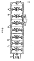
- FIG. 5 The prototype accelerator constructed to test the new coupling cavity is shown in FIG. 5.
- a series of identical half-cavity pieces 30 of OFHC copper are brazed together alternately back to back and front to front as shown.
- Slightly modified coupler half cells 32 are used to admit microwave energy.
- Slightly shorter buncher pieces 34 are used to increase the beam velocity to match the phase of the accelerating section.
- a beam source 36 inserts a beam into the buncher. The high energy beam strikes a target or window 38 at the end opposite to that of the beam source.
- the measured and theoretical dispersion curves for the brazed guide are shown in FIG. 6.
- the bead drop data is shown in Figure 6.
- the guide had a measured Q o of 13,500 and O ex t of 6,580, with a VSWR (Beta o ) of 2.05.
- the nearest neighbor coupling, K 1 was 3.3% and the next nearest neighbor coupling was .04%.
- the coupling cavity frequencies were 3001.5 MHz, + 1.5 MHz.
- the accelerating cells remained tuned to within + .1 MHz of a fixed frequency. These frequency variations were acceptable and no post-braze tuning of the guide was done.
Landscapes
- Physics & Mathematics (AREA)
- Engineering & Computer Science (AREA)
- Plasma & Fusion (AREA)
- Spectroscopy & Molecular Physics (AREA)
- Particle Accelerators (AREA)
Applications Claiming Priority (2)
| Application Number | Priority Date | Filing Date | Title |
|---|---|---|---|
| US73317585A | 1985-05-13 | 1985-05-13 | |
| US733175 | 1985-05-13 |
Publications (3)
| Publication Number | Publication Date |
|---|---|
| EP0202097A2 true EP0202097A2 (de) | 1986-11-20 |
| EP0202097A3 EP0202097A3 (en) | 1987-12-02 |
| EP0202097B1 EP0202097B1 (de) | 1989-11-23 |
Family
ID=24946543
Family Applications (1)
| Application Number | Title | Priority Date | Filing Date |
|---|---|---|---|
| EP19860303603 Expired EP0202097B1 (de) | 1985-05-13 | 1986-05-12 | Linearbeschleuniger geringen Durchmessers mit stehenden Wellen |
Country Status (3)
| Country | Link |
|---|---|
| EP (1) | EP0202097B1 (de) |
| JP (1) | JPS622500A (de) |
| DE (1) | DE3667127D1 (de) |
Cited By (2)
| Publication number | Priority date | Publication date | Assignee | Title |
|---|---|---|---|---|
| RU2143792C1 (ru) * | 1996-05-21 | 1999-12-27 | Государственный научный центр РФ - Институт теоретической и экспериментальной физики | Линейный ускоритель ионов |
| CN115866871A (zh) * | 2022-10-27 | 2023-03-28 | 成都奕康真空电子技术有限责任公司 | 一种直线加速器用新型环耦合结构 |
Family Cites Families (1)
| Publication number | Priority date | Publication date | Assignee | Title |
|---|---|---|---|---|
| FR2258080B1 (de) * | 1974-01-15 | 1978-06-09 | Cgr Mev |
-
1986
- 1986-05-12 EP EP19860303603 patent/EP0202097B1/de not_active Expired
- 1986-05-12 DE DE8686303603T patent/DE3667127D1/de not_active Expired
- 1986-05-13 JP JP10782986A patent/JPS622500A/ja active Pending
Cited By (2)
| Publication number | Priority date | Publication date | Assignee | Title |
|---|---|---|---|---|
| RU2143792C1 (ru) * | 1996-05-21 | 1999-12-27 | Государственный научный центр РФ - Институт теоретической и экспериментальной физики | Линейный ускоритель ионов |
| CN115866871A (zh) * | 2022-10-27 | 2023-03-28 | 成都奕康真空电子技术有限责任公司 | 一种直线加速器用新型环耦合结构 |
Also Published As
| Publication number | Publication date |
|---|---|
| EP0202097A3 (en) | 1987-12-02 |
| EP0202097B1 (de) | 1989-11-23 |
| DE3667127D1 (en) | 1989-12-28 |
| JPS622500A (ja) | 1987-01-08 |
Similar Documents
| Publication | Publication Date | Title |
|---|---|---|
| US4988919A (en) | Small-diameter standing-wave linear accelerator structure | |
| EP1584221B1 (de) | Linearbeschleuniger für ionenstrahlbeschleunigung | |
| US5578909A (en) | Coupled-cavity drift-tube linac | |
| Tantawi et al. | Design and demonstration of a distributed-coupling linear accelerator structure | |
| Padamsee et al. | RF superconductivity for accelerators | |
| US5014014A (en) | Plane wave transformer linac structure | |
| US6313710B1 (en) | Interaction structure with integral coupling and bunching section | |
| EP0202097B1 (de) | Linearbeschleuniger geringen Durchmessers mit stehenden Wellen | |
| Kamigaito et al. | Construction of a variable-frequency radio-frequency quadrupole linac for the RIKEN heavy-ion linac | |
| Grow et al. | Impedance calculations for travelling wave gyrotrons operating at harmonics of the cyclotron frequency in magnetron-type circuits | |
| Tanabe et al. | A small diameter standing wave linear accelerator structure | |
| Agustsson et al. | Split structure particle accelerators | |
| Labrie et al. | The coaxial coupled linac structure | |
| Xiang et al. | A Portable X-band on-axis standing wave linac structure | |
| Manca et al. | High energy accelerating structures for High gradient proton linac applications | |
| Mitra et al. | RF Test and Commissioning of the Radio Frequency Structures of the TRIUMF ISAC I facility | |
| Billen et al. | A versatile, high-power proton linac for accelerator driven transmutation technologies | |
| Swenson et al. | First Performance of the RFD Linac Structure | |
| Stokes et al. | A spiral-resonator radio-frequency quadrupole accelerator structure | |
| Schriber | Accelerator structure development for room-temperature linacs | |
| Tanabe et al. | Linear Accelerator Structure | |
| Zhang et al. | Study of a novel compact standing wave RF linac | |
| Shu | DEVELOPMENT AND TEST OF AN ACCELERATING CAVITY SHAPE FOR A SUPERCONDUCTING LINEAR COLLIDER | |
| Schempp et al. | RFQ Injector for HERA | |
| Kang et al. | Design and construction of planar mm‐wave accelerating cavity structures |
Legal Events
| Date | Code | Title | Description |
|---|---|---|---|
| PUAI | Public reference made under article 153(3) epc to a published international application that has entered the european phase |
Free format text: ORIGINAL CODE: 0009012 |
|
| AK | Designated contracting states |
Kind code of ref document: A2 Designated state(s): CH DE FR GB LI SE |
|
| 17P | Request for examination filed |
Effective date: 19861031 |
|
| PUAL | Search report despatched |
Free format text: ORIGINAL CODE: 0009013 |
|
| AK | Designated contracting states |
Kind code of ref document: A3 Designated state(s): CH DE FR GB LI SE |
|
| 17Q | First examination report despatched |
Effective date: 19890123 |
|
| GRAA | (expected) grant |
Free format text: ORIGINAL CODE: 0009210 |
|
| AK | Designated contracting states |
Kind code of ref document: B1 Designated state(s): CH DE FR GB LI SE |
|
| REF | Corresponds to: |
Ref document number: 3667127 Country of ref document: DE Date of ref document: 19891228 |
|
| ET | Fr: translation filed | ||
| PLBE | No opposition filed within time limit |
Free format text: ORIGINAL CODE: 0009261 |
|
| 26N | No opposition filed | ||
| PGFP | Annual fee paid to national office [announced via postgrant information from national office to epo] |
Ref country code: GB Payment date: 19910502 Year of fee payment: 6 |
|
| PGFP | Annual fee paid to national office [announced via postgrant information from national office to epo] |
Ref country code: SE Payment date: 19910521 Year of fee payment: 6 |
|
| PGFP | Annual fee paid to national office [announced via postgrant information from national office to epo] |
Ref country code: FR Payment date: 19910522 Year of fee payment: 6 |
|
| PGFP | Annual fee paid to national office [announced via postgrant information from national office to epo] |
Ref country code: DE Payment date: 19910531 Year of fee payment: 6 |
|
| PGFP | Annual fee paid to national office [announced via postgrant information from national office to epo] |
Ref country code: CH Payment date: 19910606 Year of fee payment: 6 |
|
| PG25 | Lapsed in a contracting state [announced via postgrant information from national office to epo] |
Ref country code: GB Effective date: 19920512 |
|
| PG25 | Lapsed in a contracting state [announced via postgrant information from national office to epo] |
Ref country code: SE Effective date: 19920513 |
|
| PG25 | Lapsed in a contracting state [announced via postgrant information from national office to epo] |
Ref country code: LI Effective date: 19920531 Ref country code: CH Effective date: 19920531 |
|
| GBPC | Gb: european patent ceased through non-payment of renewal fee |
Effective date: 19920512 |
|
| PG25 | Lapsed in a contracting state [announced via postgrant information from national office to epo] |
Ref country code: FR Effective date: 19930129 |
|
| REG | Reference to a national code |
Ref country code: CH Ref legal event code: PL |
|
| PG25 | Lapsed in a contracting state [announced via postgrant information from national office to epo] |
Ref country code: DE Effective date: 19930202 |
|
| REG | Reference to a national code |
Ref country code: FR Ref legal event code: ST |
|
| EUG | Se: european patent has lapsed |
Ref document number: 86303603.4 Effective date: 19921204 |