EP1584133B1 - Elektrische maschine für den propulsionsantrieb eines u-boots mit einer permanentmagnetisch erregten synchronmaschine - Google Patents
Elektrische maschine für den propulsionsantrieb eines u-boots mit einer permanentmagnetisch erregten synchronmaschine Download PDFInfo
- Publication number
- EP1584133B1 EP1584133B1 EP03815525A EP03815525A EP1584133B1 EP 1584133 B1 EP1584133 B1 EP 1584133B1 EP 03815525 A EP03815525 A EP 03815525A EP 03815525 A EP03815525 A EP 03815525A EP 1584133 B1 EP1584133 B1 EP 1584133B1
- Authority
- EP
- European Patent Office
- Prior art keywords
- electric machine
- winding
- inverters
- stator
- phase
- Prior art date
- Legal status (The legal status is an assumption and is not a legal conclusion. Google has not performed a legal analysis and makes no representation as to the accuracy of the status listed.)
- Expired - Lifetime
Links
Images

Classifications
-
- B—PERFORMING OPERATIONS; TRANSPORTING
- B63—SHIPS OR OTHER WATERBORNE VESSELS; RELATED EQUIPMENT
- B63G—OFFENSIVE OR DEFENSIVE ARRANGEMENTS ON VESSELS; MINE-LAYING; MINE-SWEEPING; SUBMARINES; AIRCRAFT CARRIERS
- B63G8/00—Underwater vessels, e.g. submarines; Equipment specially adapted therefor
- B63G8/08—Propulsion
-
- B—PERFORMING OPERATIONS; TRANSPORTING
- B63—SHIPS OR OTHER WATERBORNE VESSELS; RELATED EQUIPMENT
- B63H—MARINE PROPULSION OR STEERING
- B63H23/00—Transmitting power from propulsion power plant to propulsive elements
- B63H23/22—Transmitting power from propulsion power plant to propulsive elements with non-mechanical gearing
- B63H23/24—Transmitting power from propulsion power plant to propulsive elements with non-mechanical gearing electric
-
- H—ELECTRICITY
- H02—GENERATION; CONVERSION OR DISTRIBUTION OF ELECTRIC POWER
- H02K—DYNAMO-ELECTRIC MACHINES
- H02K11/00—Structural association of dynamo-electric machines with electric components or with devices for shielding, monitoring or protection
- H02K11/30—Structural association with control circuits or drive circuits
- H02K11/33—Drive circuits, e.g. power electronics
-
- H—ELECTRICITY
- H02—GENERATION; CONVERSION OR DISTRIBUTION OF ELECTRIC POWER
- H02M—APPARATUS FOR CONVERSION BETWEEN AC AND AC, BETWEEN AC AND DC, OR BETWEEN DC AND DC, AND FOR USE WITH MAINS OR SIMILAR POWER SUPPLY SYSTEMS; CONVERSION OF DC OR AC INPUT POWER INTO SURGE OUTPUT POWER; CONTROL OR REGULATION THEREOF
- H02M1/00—Details of apparatus for conversion
- H02M1/10—Arrangements incorporating converting means for enabling loads to be operated at will from different kinds of power supplies, e.g. from AC or DC
-
- H—ELECTRICITY
- H02—GENERATION; CONVERSION OR DISTRIBUTION OF ELECTRIC POWER
- H02M—APPARATUS FOR CONVERSION BETWEEN AC AND AC, BETWEEN AC AND DC, OR BETWEEN DC AND DC, AND FOR USE WITH MAINS OR SIMILAR POWER SUPPLY SYSTEMS; CONVERSION OF DC OR AC INPUT POWER INTO SURGE OUTPUT POWER; CONTROL OR REGULATION THEREOF
- H02M5/00—Conversion of AC power input into AC power output, e.g. for change of voltage, for change of frequency, for change of number of phases
- H02M5/40—Conversion of AC power input into AC power output, e.g. for change of voltage, for change of frequency, for change of number of phases with intermediate conversion into DC
- H02M5/42—Conversion of AC power input into AC power output, e.g. for change of voltage, for change of frequency, for change of number of phases with intermediate conversion into DC by static converters
- H02M5/44—Conversion of AC power input into AC power output, e.g. for change of voltage, for change of frequency, for change of number of phases with intermediate conversion into DC by static converters using discharge tubes or semiconductor devices to convert the intermediate DC into AC
- H02M5/453—Conversion of AC power input into AC power output, e.g. for change of voltage, for change of frequency, for change of number of phases with intermediate conversion into DC by static converters using discharge tubes or semiconductor devices to convert the intermediate DC into AC using devices of a triode or transistor type requiring continuous application of a control signal
- H02M5/458—Conversion of AC power input into AC power output, e.g. for change of voltage, for change of frequency, for change of number of phases with intermediate conversion into DC by static converters using discharge tubes or semiconductor devices to convert the intermediate DC into AC using devices of a triode or transistor type requiring continuous application of a control signal using semiconductor devices only
-
- H—ELECTRICITY
- H02—GENERATION; CONVERSION OR DISTRIBUTION OF ELECTRIC POWER
- H02K—DYNAMO-ELECTRIC MACHINES
- H02K16/00—Machines with more than one rotor or stator
- H02K16/04—Machines with one rotor and two stators
-
- H—ELECTRICITY
- H02—GENERATION; CONVERSION OR DISTRIBUTION OF ELECTRIC POWER
- H02K—DYNAMO-ELECTRIC MACHINES
- H02K3/00—Details of windings
- H02K3/04—Windings characterised by the conductor shape, form or construction, e.g. with bar conductors
- H02K3/28—Layout of windings or of connections between windings
Definitions
- the invention relates to an electric machine for the propulsion drive of a submarine with a permanent-magnetically excited synchronous machine, with a stator in which a stator winding is arranged.
- a stator in which a stator winding is arranged.
- To the synchronous machine includes a rotor, are provided on the permanent magnets.
- Such an electrical machine as used for example in the EP-B-0 194 433 is described in more detail, is increasingly being used in propulsion equipment of submarines, since their use for such purposes, inter alia, associated with a significant reduction in the required space, resulting in a considerable cost savings can be incurred on the boatbuilding side.
- MAGENS K "PERMASYN - A PERMANENT SINGLE SYNCHRONOUS MOTOR FOR SHIPPING PERMASYN - A PERMANENT FIELD, CONVERTER-FED MOTOR FOR PROPULSION SYSTEMS" YEARBOOK OF SHIPBUILDING TECHNOLOGY, BERLIN, DE, Vol. 81, 1987, pages 221-227, XP002043270 ISSN : 0374-1222 discloses a generic electric machine for the propulsion of a submarine.
- the invention has the object of providing such an electric machine for the propulsion of a submarine with a permanent magnet synchronized machine such that an increased compared to the prior art redundancy and availability is realized, with low technical and design effort a high Reducing the noise generated during operation of the electrical machine should be achievable and should be guaranteed in comparison to the prior art, an increased level of Windungsund Erdschlupiping.
- each winding strand is fed by a single-phase inverter, results in a considerably increased degree of turn and Erdschluriol compared to the prior art; Furthermore, it is possible to operate the thus configured electric machine even with a single-pole winding and ground fault.
- the inverter provided in the converter inside the machine housing in the axial direction between the A and the B-side end shield high compactness of the entire drive system of the submarine and a substantial insensitivity to external interference is achieved, in addition to the of the Converters outgoing EMC interference are largely reduced.
- each phase winding of the stator winding designed as a wave winding is fed by a separate single-phase converter, high redundancy is achievable. Furthermore, owing to the separate supply by single-phase converters, it is also possible to use the harmonic waves of the electromagnetic field in a beneficial manner for the generation of torque, since the phase currents of the stator currents can be realized by the single-phase supply of the phase windings. In particular, in this context it is possible to choose the time courses of the stator currents so that the disturbing pendulum moments are very small and thus the high demands on the low noise for propulsion systems of submarines can be met.
- the converters of the above-described electric machine are advantageously designed in modular design.
- the electric machine according to the invention is the wave winding designed as a rod winding.
- the electric machine according to the invention designed as a wave winding stator winding of the permanent magnetically excited synchronous machine has an even number of winding strands, so that two inverters can be arranged in each inverter module in an advantageous manner. By choosing an even number of winding phases and converters, it is also possible in an advantageous manner to connect each half of the inverter to one of two subnetworks of the electrical system and thereby achieve a uniform load sharing on both subnets.
- the permanent-magnetically excited synchronous machine of the electric machine according to the invention can advantageously have 24 winding strands to which 24 inverters and 12 converter modules are assigned, wherein two inverters are respectively arranged in the converter modules.
- each inverter module has one or more inverters.
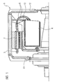
- FIGURE 1 in schematic form shown in partial section electrical machine with a permanent-magnetically excited synchronous machine 1 is used in submarines as propulsion drive.
- An integral part of the permanent-magnetically excited synchronous machine 1 of such a drive system is a stator 2 with a stator winding 3.
- the stator winding 3 is formed as a wave winding 3.
- This designed as a wave winding 3 stator winding 3 has, as can be seen in particular from the basic illustration in FIGURE 2 results in a plurality of winding strands 4, of which in the case of in FIGURE 2 basically shown stator winding 3 24 winding strands 4 are provided.
- each individual winding strand 4 to a converter WR101 to WR112 or WR201 to WR212 assigned to it alone takes place by means of connecting lines 5.
- Each winding strand 4 of the stator winding 3 of the synchronous machine 1 designed as wave winding 3 is provided by the one, only for this winding strand 4 Inverter WR powered.
- the inverters WR, which feed the stator winding 3, are arranged in the interior of the permanently magnetically excited synchronous machine 1 in the axial direction between an A-side end shield 11 and a B-side end shield 12 in an inverter holding frame 13 and are located in converter modules 6.
- inverters WR there are two inverters WR each, namely inverters WR101 and WR102, inverters WR103 and WR104, inverters WR105 and WR106, inverters WR107 and WR108, inverters WR109 and WR110, inverters WR111 and WR112, inverters WR201 and WR202 , inverters WR203 and WR204, inverters WR205 and WR206, inverters WR207 and WR208, inverters WR209 and WR210 and the inverters WR211 and WR121 combined to form a converter module 6.
- Each six converter modules 6 are connected via a connection line provided for them 7 and 8 respectively to a subnet 9 and 10 of a vehicle electrical system.
Landscapes
- Engineering & Computer Science (AREA)
- Power Engineering (AREA)
- Mechanical Engineering (AREA)
- Chemical & Material Sciences (AREA)
- Combustion & Propulsion (AREA)
- Ocean & Marine Engineering (AREA)
- Aviation & Aerospace Engineering (AREA)
- Microelectronics & Electronic Packaging (AREA)
- Permanent Magnet Type Synchronous Machine (AREA)
- Windings For Motors And Generators (AREA)
- Linear Motors (AREA)
- Control Of Ac Motors In General (AREA)
- Drilling And Exploitation, And Mining Machines And Methods (AREA)
- Motor Or Generator Frames (AREA)
- Control Of Electric Motors In General (AREA)
- Iron Core Of Rotating Electric Machines (AREA)
- Dynamo-Electric Clutches, Dynamo-Electric Brakes (AREA)
- Manufacture Of Motors, Generators (AREA)
Description
- Die Erfindung bezieht sich auf eine elektrische Maschine für den Propulsionsantrieb eines U-Boots mit einer permanentmagnetisch erregten Synchronmaschine, mit einem Ständer, in dem eine Ständerwicklung angeordnet ist. Zu der Synchronmaschine gehört ein Läufer, auf dem Permanentmagnete vorgesehen sind.
- Eine derartige elektrische Maschine, wie sie beispielsweise in der
EP-B-0 194 433 näher beschrieben ist, kommt zunehmend in Antriebseinrichtungen von U-Booten zum Einsatz, da ihre Verwendung für derartige Zwecke u.a. mit einer erheblichen Reduzierung des erforderlichen Platzbedarfs einhergeht, woraus sich bootsbauseitig erhebliche Kosteneinsparungen ergeben können. - MAGENS K: "PERMASYN - EIN PERMANENTERREGTER SYNCHRONMOTOR FUER DEN SCHIFFSBETRIEB. PERMASYN - A PERMANENT-FIELD, CONVERTER-FED MOTOR FOR PROPULSION SYSTEMS" JAHRBUCH DER SCHIFFBAUTECHNISCHEN GESELLSCHAFT, BERLIN, DE, Bd. 81, 1987, Seiten 221-227, XP002043270 ISSN: 0374-1222 offenbart eine gattungsgemässe elektrische Maschine für den Propulsionsantrieb eines U-Boots.
- Der Erfindung liegt die Aufgabe zugrunde, eine derartige elektrische Maschine für den Propulsionsantrieb eines U-Boots mit einer permanentmagnetisch erregten Synchronmaschine derart weiterzubilden, dass eine im Vergleich zum Stand der Technik erhöhte Redundanz und Verfügbarkeit realisiert wird, wobei mit geringem technisch-konstruktiven Aufwand eine hohe Reduzierung der im Betrieb der elektrischen Maschine entstehenden Geräusche erreichbar sein soll und im Vergleich zum Stand der Technik ein erhöhtes Maß an Windungs- und Erdschlusssicherheit gewährleistet sein soll.
- Diese Aufgabe wird erfindungsgemäß durch die Merkmale des Anspruchs 1 gelöst. Bevorzugte Ausgestaltungen sind in den abhängigen Ansprüchen definiert.
- Aufgrund der Ausgestaltung der Ständerwicklung als Wellenwicklung, die eine Vielzahl einzelne Wicklungsstränge aufweist, wobei jeder Wicklungsstrang durch einen einphasigen Umrichter gespeist wird, ergibt sich ein im Vergleich zum Stand der Technik beträchtlich erhöhtes Maß an Windungs- und Erdschlusssicherheit; des weiteren ist es möglich, die derart ausgestaltete elektrische Maschine auch bei einem einpoligen Windungs- und Erdschluss weiter zu betreiben. Durch die Anordnung der in Umrichtermodulen vorgesehenen Umrichter innerhalb des Maschinengehäuses in axialer Richtung zwischen dem A-und dem B-seitigen Lagerschild wird eine hohe Kompaktheit der gesamten Antriebsanlage des U-Boots und eine weitgehende Unempfindlichkeit gegenüber äußeren Störeinflüssen erreicht, wobei darüber hinaus die von den Umrichtern ausgehenden EMV-Störbeeinflussungen weitestgehend reduziert werden. Da jeder Wicklungsstrang der als Wellenwicklung ausgebildeten Ständerwicklung durch einen separaten einphasigen Umrichter gespeist wird, ist eine hohe Redundanz erreichbar. Des Weiteren ergibt sich aufgrund der separaten Speisung durch einphasige Umrichter die Möglichkeit, auch die Oberwellen des elektromagnetischen Feldes nutzbringend zur Drehmomentenbildung zu verwenden, da sich durch die einphasige Speisung der Wicklungsstränge nahezu beliebige zeitliche Verläufe der Ständerströme realisieren lassen. Insbesondere besteht in diesem Zusammenhang die Möglichkeit, die Zeitverläufe der Ständerströme so zu wählen, dass die störenden Pendelmomente sehr klein werden und damit die hohen Anforderungen an die Geräuscharmut für Antriebsanlagen von U-Booten erfüllt werden können. Die Umrichter der vorstehend geschilderten elektrischen Maschine sind in vorteilhafter Weise in Modulbauweise ausgeführt.
- Gemäß einer weiteren vorteilhaften Ausgestaltung der erfindungsgemäßen elektrischen Maschine ist deren Wellenwicklung als Stabwicklung ausgebildet. Gemäß einer weiteren vorteilhaften Ausführungsform der erfindungsgemäßen elektrischen Maschine hat die als Wellenwicklung ausgebildete Ständerwicklung der permanentmagnetisch erregten Synchronmaschine eine geradzahlige Anzahl von Wicklungssträngen, so dass in jedem Umrichtermodul in vorteilhafter Weise zwei Umrichter angeordnet werden können. Durch die Wahl einer geradzahligen Anzahl von Wicklungssträngen und Umrichtern ist es weiterhin in vorteilhafter Weise möglich, jeweils die Hälfte der Umrichter an ein von zwei Teilnetzen des Bordnetzes anzuschließen und dabei eine gleichmäßige Lastaufteilung auf beide Teilnetze zu erreichen.
- Die permanentmagnetisch erregte Synchronmaschine der erfindungsgemäßen elektrischen Maschine kann vorteilhaft 24 Wicklungsstränge aufweisen, denen 24 Umrichter und 12 Umrichtermodule zugeordnet sind, wobei in den Umrichtermodulen jeweils zwei Umrichter angeordnet sind.
- Es ist möglich, dass jedes Umrichtermodul ein oder mehrere Umrichter aufweist.
- Im folgenden wird die Erfindung anhand einer Ausführungsform unter Bezugnahme auf die Zeichnung näher erläutert.
- Es zeigen:
- FIGUR 1
- einen Teilschnitt einer prinzipiellen Ausführungsform einer erfindungsgemäßen elektrischen Maschine mit ei- ner permanent magnetisch erregten Synchronmaschine und innerhalb des Maschinengehäuses angeordneten Um- richtern; und
- FIGUR 2
- eine Prinzipdarstellung einer Anordnung von Wick- lungssträngen und Umrichtern der in
FIGUR 1 gezeigten Ausführungsform der erfindungsgemäßen elektrischen Maschine. - Eine in
FIGUR 1 in prinzipieller Form im Teilschnitt dargestellte elektrische Maschine mit einer permanentmagnetisch erregten Synchronmaschine 1 wird in U-Booten als Propulsionsantrieb eingesetzt. Ein wesentlicher Bestandteil der permanentmagnetisch erregten Synchronmaschine 1 einer derartigen Antriebsanlage ist ein Ständer 2 mit einer Ständerwicklung 3. - Im Falle der erfindungsgemäßen Ausführungsform der elektrischen Maschine ist die Ständerwicklung 3 als Wellenwicklung 3 ausgebildet. Diese als Wellenwicklung 3 ausgebildete Ständerwicklung 3, hat, wie sich insbesondere aus der prinzipiellen Darstellung in
FIGUR 2 ergibt, eine Vielzahl von Wicklungssträngen 4, von denen im Falle der inFIGUR 2 prinzipiell gezeigten Ständerwicklung 3 24 Wicklungsstränge 4 vorgesehen sind. - Der Anschluss jedes einzelnen Wicklungsstrangs 4 an einen ihm allein zugeordneten Umrichter WR101 bis WR112 bzw. WR201 bis WR212 erfolgt mittels Verbindungsleitungen 5. Jeder Wicklungsstrang 4 der als Wellenwicklung 3 ausgebildeten Ständerwicklung 3 der Synchronmaschine 1 wird durch den jeweils einen, nur für diesen Wicklungsstrang 4 vorgesehenen Umrichter WR gespeist. Die Umrichter WR, die die Ständerwicklung 3 speisen, sind im Inneren der permanentmagnetisch erregten Synchronmaschine 1 in axialer Richtung zwischen einem A-seitigen Lagerschild 11 und einem B-seitigen Lagerschild 12 in einem Umrichterhaltegerüst 13 angeordnet und befinden sich in Umrichtermodulen 6.
- Bei dem in
FIGUR 2 gezeigten Ausführungsbeispiel sind jeweils zwei Umrichter WR, nämlich die Umrichter WR101 und WR102, die Umrichter WR103 und WR104, die Umrichter WR105 und WR106, die umrichter WR107 und WR108, die Umrichter WR109 und WR110, die Umrichter WR111 und WR112, die Umrichter WR201 und WR202, die Umrichter WR203 und WR204, die Umrichter WR205 und WR206, die Umrichter WR207 und WR208, die Umrichter WR209 und WR210 und die Umrichter WR211 und WR121 zu einem Umrichtermodul 6 zusammengefaßt. - Jeweils sechs Umrichtermodule 6 sind über eine für sie vorgesehene Anschlussleitung 7 bzw. 8 an jeweils ein Teilnetz 9 bzw. 10 eines Bordnetzes angeschlossen.
- Anstelle von zwei Umrichtern WR je Umrichtermodul 6 können mehr als zwei Umrichter WR zu einem Umrichtermodul zusammengefasst sein.
Claims (6)
- Elektrische Maschine für den Propulsionsantrieb eines U-Boots mit einer permanentmagnetisch erregten Synchronmaschine (1), mit einem Ständer (2), in dem eine Ständerwicklung (3) angeordnet ist, die eine Vielzahl Wicklungsstränge (4) aufweist, wobei jeder Wicklungsstrang (4) durch einen separaten, einphasigen Umrichter (WR) gespeist ist, wobei sich die Umrichter (WR) in Form von Umrichtermodulen (6) im inneren der Synchronmaschine (1) befinden und die Umrichter (WR) in axialer Richtung zwischen einem A-seitigen Lagerschild (11) und einem B-seitigen Lagerschild (12) in einem Umrichterhaltegerüst (13) angeordnet sind,
dadurch gekennzeichnet, dass die Ständerwicklung als Wellenwicklung ausgebildet ist. - Elektrische Maschine nach Anspruch 1, deren Wellenwicklung (3) als Stabwicklung ausgebildet ist.
- Elektrische Maschine nach Anspruch 1 oder 2, deren Wellenwicklung (3) eine geradzahlige Anzahl von Wicklungssträngen (4) aufweist, denen eine ebenso große Anzahl von Umrichtern (WR) zugeordnet ist.
- Elektrische Maschine nach einem der Ansprüche 1 bis 3, bei der Umrichtermodule (6) vorgesehen sind, in denen jeweils ein, zwei oder mehrere Umrichter (WR) angeordnet ist bzw. sind.
- Elektrische Maschine nach einem der Ansprüche 1 bis 4, bei der jeweils die Hälfte der Umrichter (WR) an ein von zwei Teilnetzen (9, 10) des Bordnetzes angeschlossen ist.
- Elektrische Maschine nach einem der Ansprüche 1 bis 5, deren Synchronmaschine (1) 24 Wicklungsstränge (4) aufweist, denen 24 Umrichter (WR) und 12 Umrichtermodule (6) zugeordnet sind, in denen jeweils Umrichter (WR) angeordnet sind.
Applications Claiming Priority (3)
| Application Number | Priority Date | Filing Date | Title |
|---|---|---|---|
| DE10301272 | 2003-01-15 | ||
| DE10301272A DE10301272A1 (de) | 2003-01-15 | 2003-01-15 | Elektrische Maschine für den Propulsionsantrieb eines U-Boots mit einer permanentmagnetisch erregten Synchronmaschine |
| PCT/DE2003/004221 WO2004068694A1 (de) | 2003-01-15 | 2003-12-19 | Elektrische maschine für den propulsionsantrieb eines u-boots mit einer permanentmagnetisch erregten synchronmaschine |
Publications (2)
| Publication Number | Publication Date |
|---|---|
| EP1584133A1 EP1584133A1 (de) | 2005-10-12 |
| EP1584133B1 true EP1584133B1 (de) | 2010-05-12 |
Family
ID=32667602
Family Applications (1)
| Application Number | Title | Priority Date | Filing Date |
|---|---|---|---|
| EP03815525A Expired - Lifetime EP1584133B1 (de) | 2003-01-15 | 2003-12-19 | Elektrische maschine für den propulsionsantrieb eines u-boots mit einer permanentmagnetisch erregten synchronmaschine |
Country Status (9)
| Country | Link |
|---|---|
| EP (1) | EP1584133B1 (de) |
| KR (1) | KR101089845B1 (de) |
| CN (1) | CN1327605C (de) |
| AT (1) | ATE467947T1 (de) |
| AU (1) | AU2003296539A1 (de) |
| BR (1) | BR0318000A (de) |
| DE (2) | DE10301272A1 (de) |
| ES (1) | ES2343796T3 (de) |
| WO (1) | WO2004068694A1 (de) |
Families Citing this family (20)
| Publication number | Priority date | Publication date | Assignee | Title |
|---|---|---|---|---|
| US7452251B2 (en) | 2006-01-20 | 2008-11-18 | Torqeedo Gmbh | Integrated outboard motor |
| EP1810920A1 (de) * | 2006-01-20 | 2007-07-25 | Torqeedo GmbH | Elektrischer Aussenbordmotor mit integriertem, elektronischem Umrichter |
| DE102007029366A1 (de) | 2007-06-26 | 2009-01-02 | Siemens Ag | Elektrische Maschine mit vereinfachter Drehwinkelgeberausrichtung |
| DE102007054719A1 (de) | 2007-06-28 | 2009-01-08 | Universität Bremen | Elektrische Drehfeldmaschine |
| DE102007034741A1 (de) | 2007-07-25 | 2009-01-29 | Siemens Ag | Elektrische Maschine mit Öffnungen im Lagerschildunterteil |
| DE102010029370A1 (de) * | 2010-05-27 | 2011-12-01 | Siemens Aktiengesellschaft | U-Boot-Propulsionsantriebssystem |
| CN102060096B (zh) * | 2010-12-20 | 2013-04-17 | 庞志森 | 电动船舶的永磁同步电动机矢量控制无齿轮箱推进装置 |
| DE102011006355B4 (de) * | 2011-03-29 | 2016-11-03 | Siemens Aktiengesellschaft | Antrieb zum Antreiben eines Unterseeboots oder eines Schiffs |
| DE102011007599A1 (de) | 2011-04-18 | 2012-10-18 | Siemens Aktiengesellschaft | Verfahren zum Betrieb eines Unterseebootes sowie Unterseeboot |
| KR101627416B1 (ko) | 2014-08-13 | 2016-06-03 | 대우조선해양 주식회사 | 잠수함의 추진 시스템 및 방법 |
| DE102016209602A1 (de) | 2016-06-01 | 2017-12-07 | Siemens Aktiengesellschaft | Elektrische Maschine |
| DE102016209606A1 (de) | 2016-06-01 | 2017-12-07 | Siemens Aktiengesellschaft | Verfahren zum Betrieb einer elektrischen Maschine |
| WO2017207283A1 (de) * | 2016-06-01 | 2017-12-07 | Siemens Aktiengesellschaft | Verfahren zum betrieb einer elektrischen maschine |
| US11063323B2 (en) | 2019-01-23 | 2021-07-13 | H55 Sa | Battery module for electrically-driven aircraft |
| US11148819B2 (en) | 2019-01-23 | 2021-10-19 | H55 Sa | Battery module for electrically-driven aircraft |
| US12409756B2 (en) | 2017-04-05 | 2025-09-09 | H55 Sa | Aircraft monitoring system and method for electric or hybrid aircrafts |
| US11065979B1 (en) | 2017-04-05 | 2021-07-20 | H55 Sa | Aircraft monitoring system and method for electric or hybrid aircrafts |
| US10479223B2 (en) | 2018-01-25 | 2019-11-19 | H55 Sa | Construction and operation of electric or hybrid aircraft |
| US10854866B2 (en) | 2019-04-08 | 2020-12-01 | H55 Sa | Power supply storage and fire management in electrically-driven aircraft |
| DE102020209302A1 (de) | 2020-07-23 | 2022-01-27 | Siemens Energy Global GmbH & Co. KG | Betreiben einer Antriebseinrichtung |
Family Cites Families (10)
| Publication number | Priority date | Publication date | Assignee | Title |
|---|---|---|---|---|
| BR7708491A (pt) * | 1976-12-21 | 1978-09-12 | Mitsubishi Electric Corp | Aparelho de alimentacao de corrente alternada,gerador de campo rotativo,motor a comutador solido e motor de corrente alternada |
| US4550267A (en) * | 1983-02-18 | 1985-10-29 | Sundstrand Corporation | Redundant multiple channel electric motors and generators |
| FR2541529A1 (fr) * | 1983-02-18 | 1984-08-24 | Sundstrand Corp | Machine electromotrice a canaux multiples |
| EP0126997B1 (de) * | 1983-05-02 | 1989-01-25 | Herbert Prof. Dr. Weh | Elektrischer Antrieb |
| DE3401164A1 (de) * | 1983-07-14 | 1985-01-24 | Weh Herbert | Vielphasenschaltung fuer die ankerwicklung elektrischer maschinen und freqenzumrichter |
| NO167489C (no) * | 1985-02-11 | 1991-11-06 | Siemens Ag | Omrettermatet dreiefeltmaskin med elektronisk innstillingsorgan |
| DE9017835U1 (de) * | 1990-10-04 | 1992-03-12 | Robert Bosch Gmbh, 7000 Stuttgart | Ständer für elektrische Maschinen |
| WO1998054822A1 (fr) * | 1997-05-26 | 1998-12-03 | Denso Corporation | Alternateur pour vehicule |
| JP2002204563A (ja) * | 2001-01-04 | 2002-07-19 | Daiwa Engineering:Kk | 周波数変換機 |
| JP3672846B2 (ja) * | 2001-05-29 | 2005-07-20 | 三菱電機株式会社 | 車両用交流発電機 |
-
2003
- 2003-01-15 DE DE10301272A patent/DE10301272A1/de not_active Ceased
- 2003-12-19 WO PCT/DE2003/004221 patent/WO2004068694A1/de not_active Ceased
- 2003-12-19 CN CNB200380108791XA patent/CN1327605C/zh not_active Expired - Fee Related
- 2003-12-19 AT AT03815525T patent/ATE467947T1/de not_active IP Right Cessation
- 2003-12-19 AU AU2003296539A patent/AU2003296539A1/en not_active Abandoned
- 2003-12-19 BR BR0318000-0A patent/BR0318000A/pt not_active IP Right Cessation
- 2003-12-19 ES ES03815525T patent/ES2343796T3/es not_active Expired - Lifetime
- 2003-12-19 KR KR1020057012875A patent/KR101089845B1/ko not_active Expired - Lifetime
- 2003-12-19 DE DE50312714T patent/DE50312714D1/de not_active Expired - Lifetime
- 2003-12-19 EP EP03815525A patent/EP1584133B1/de not_active Expired - Lifetime
Also Published As
| Publication number | Publication date |
|---|---|
| EP1584133A1 (de) | 2005-10-12 |
| DE50312714D1 (de) | 2010-06-24 |
| CN1739232A (zh) | 2006-02-22 |
| WO2004068694A1 (de) | 2004-08-12 |
| KR20050092742A (ko) | 2005-09-22 |
| BR0318000A (pt) | 2005-11-29 |
| ES2343796T3 (es) | 2010-08-10 |
| CN1327605C (zh) | 2007-07-18 |
| AU2003296539A1 (en) | 2004-08-23 |
| KR101089845B1 (ko) | 2011-12-05 |
| ATE467947T1 (de) | 2010-05-15 |
| DE10301272A1 (de) | 2004-08-05 |
Similar Documents
| Publication | Publication Date | Title |
|---|---|---|
| EP1584133B1 (de) | Elektrische maschine für den propulsionsantrieb eines u-boots mit einer permanentmagnetisch erregten synchronmaschine | |
| EP3224929B1 (de) | Permanenterregte synchronmaschine und kraftfahrzeugsystem | |
| EP1864375B1 (de) | Generator mit hoher phasenordnung | |
| DE102009027220A1 (de) | Vorrichtung zur Versorgung eines elektrischen Antriebes für ein Kraftfahrzeug | |
| DE102007054228A1 (de) | Stator einer dynamoelektrischen Maschine hoher Leistung | |
| EP2115857A2 (de) | 18/8-synchronmotor | |
| DE102014209653B4 (de) | Ansteuervorrichtung, Elektromaschine und Verfahren | |
| DE102015225095A1 (de) | Spannungsumrichter, elektrisches Antriebssystem und Verfahren zum Reduzieren von Störspannungen | |
| EP1866540B1 (de) | Schalteinrichtung zur verknüpfung verschiedener elektrischer spannungsebenen in einem kraftfahrzeug | |
| DE102014203568A1 (de) | Elektrisches Antriebssystem | |
| EP1584134B1 (de) | Verfahren zur verringerung von common-mode-störströmen in einem elektrischen antriebssystem sowie entsprechendes elektrisches antriebssystem | |
| EP0730333A2 (de) | Schiffsantriebsanlage | |
| DE102016118995A1 (de) | Aufbau eines Motor/Generators mit zugehöriger Leistungselektronik für die kontrollierte Versorgung eines Zweispannungsbordnetzes mit Leistung | |
| DE102015218110A1 (de) | Elektrische Maschine mit verbesserter Kurzschlussfestigkeit | |
| DE19522302C2 (de) | Schiffsantriebsanlage | |
| DE2309998A1 (de) | Elektrische maschine | |
| DE102014226570A1 (de) | Asynchronmaschine für sicherheitsrelevante Einsatzgebiete | |
| DE102013218197A1 (de) | Hybridmotor | |
| DE102020201547A1 (de) | Stator einer elektrischen Maschine | |
| DE102024207034B4 (de) | Traktionsnetz und EMV-Filter | |
| DE102020126340A1 (de) | Wechselrichter für eine Antriebseinrichtung eines elektrisch antreibbaren Kraftfahrzeugs | |
| EP1754299A1 (de) | Vorrichtung zur aufnahme peripherer antriebskomponenten | |
| DE102020207856A1 (de) | Inverter für eine elektrische Maschine, elektrische Maschine mit solch einem Inverter sowie Lenksystem mit solch einer elektrischen Maschine | |
| DE102016204843B3 (de) | Antriebseinrichtung für ein Kraftfahrzeug, insbesondere ein Elektro- oder Hybridfahrzeug | |
| EP0317868B1 (de) | Hilfswicklung an einem Generator unter Einbeziehung der Spannbolzen des Ständerblechpaketes |
Legal Events
| Date | Code | Title | Description |
|---|---|---|---|
| PUAI | Public reference made under article 153(3) epc to a published international application that has entered the european phase |
Free format text: ORIGINAL CODE: 0009012 |
|
| 17P | Request for examination filed |
Effective date: 20050718 |
|
| AK | Designated contracting states |
Kind code of ref document: A1 Designated state(s): AT BE BG CH CY CZ DE DK EE ES FI FR GB GR HU IE IT LI LU MC NL PT RO SE SI SK TR |
|
| AX | Request for extension of the european patent |
Extension state: AL LT LV MK |
|
| DAX | Request for extension of the european patent (deleted) | ||
| GRAP | Despatch of communication of intention to grant a patent |
Free format text: ORIGINAL CODE: EPIDOSNIGR1 |
|
| GRAS | Grant fee paid |
Free format text: ORIGINAL CODE: EPIDOSNIGR3 |
|
| GRAA | (expected) grant |
Free format text: ORIGINAL CODE: 0009210 |
|
| AK | Designated contracting states |
Kind code of ref document: B1 Designated state(s): AT BE BG CH CY CZ DE DK EE ES FI FR GB GR HU IE IT LI LU MC NL PT RO SE SI SK TR |
|
| REG | Reference to a national code |
Ref country code: GB Ref legal event code: FG4D Free format text: NOT ENGLISH |
|
| REG | Reference to a national code |
Ref country code: CH Ref legal event code: EP |
|
| REG | Reference to a national code |
Ref country code: IE Ref legal event code: FG4D Free format text: LANGUAGE OF EP DOCUMENT: GERMAN |
|
| REF | Corresponds to: |
Ref document number: 50312714 Country of ref document: DE Date of ref document: 20100624 Kind code of ref document: P |
|
| REG | Reference to a national code |
Ref country code: GR Ref legal event code: EP Ref document number: 20100401527 Country of ref document: GR |
|
| REG | Reference to a national code |
Ref country code: ES Ref legal event code: FG2A Ref document number: 2343796 Country of ref document: ES Kind code of ref document: T3 |
|
| REG | Reference to a national code |
Ref country code: SE Ref legal event code: TRGR |
|
| REG | Reference to a national code |
Ref country code: NL Ref legal event code: VDEP Effective date: 20100512 |
|
| PG25 | Lapsed in a contracting state [announced via postgrant information from national office to epo] |
Ref country code: NL Free format text: LAPSE BECAUSE OF FAILURE TO SUBMIT A TRANSLATION OF THE DESCRIPTION OR TO PAY THE FEE WITHIN THE PRESCRIBED TIME-LIMIT Effective date: 20100512 |
|
| PG25 | Lapsed in a contracting state [announced via postgrant information from national office to epo] |
Ref country code: SI Free format text: LAPSE BECAUSE OF FAILURE TO SUBMIT A TRANSLATION OF THE DESCRIPTION OR TO PAY THE FEE WITHIN THE PRESCRIBED TIME-LIMIT Effective date: 20100512 |
|
| REG | Reference to a national code |
Ref country code: IE Ref legal event code: FD4D |
|
| PG25 | Lapsed in a contracting state [announced via postgrant information from national office to epo] |
Ref country code: CY Free format text: LAPSE BECAUSE OF FAILURE TO SUBMIT A TRANSLATION OF THE DESCRIPTION OR TO PAY THE FEE WITHIN THE PRESCRIBED TIME-LIMIT Effective date: 20100512 |
|
| PG25 | Lapsed in a contracting state [announced via postgrant information from national office to epo] |
Ref country code: PT Free format text: LAPSE BECAUSE OF FAILURE TO SUBMIT A TRANSLATION OF THE DESCRIPTION OR TO PAY THE FEE WITHIN THE PRESCRIBED TIME-LIMIT Effective date: 20100913 Ref country code: IE Free format text: LAPSE BECAUSE OF FAILURE TO SUBMIT A TRANSLATION OF THE DESCRIPTION OR TO PAY THE FEE WITHIN THE PRESCRIBED TIME-LIMIT Effective date: 20100512 Ref country code: EE Free format text: LAPSE BECAUSE OF FAILURE TO SUBMIT A TRANSLATION OF THE DESCRIPTION OR TO PAY THE FEE WITHIN THE PRESCRIBED TIME-LIMIT Effective date: 20100512 Ref country code: DK Free format text: LAPSE BECAUSE OF FAILURE TO SUBMIT A TRANSLATION OF THE DESCRIPTION OR TO PAY THE FEE WITHIN THE PRESCRIBED TIME-LIMIT Effective date: 20100512 |
|
| PG25 | Lapsed in a contracting state [announced via postgrant information from national office to epo] |
Ref country code: SK Free format text: LAPSE BECAUSE OF FAILURE TO SUBMIT A TRANSLATION OF THE DESCRIPTION OR TO PAY THE FEE WITHIN THE PRESCRIBED TIME-LIMIT Effective date: 20100512 Ref country code: RO Free format text: LAPSE BECAUSE OF FAILURE TO SUBMIT A TRANSLATION OF THE DESCRIPTION OR TO PAY THE FEE WITHIN THE PRESCRIBED TIME-LIMIT Effective date: 20100512 Ref country code: CZ Free format text: LAPSE BECAUSE OF FAILURE TO SUBMIT A TRANSLATION OF THE DESCRIPTION OR TO PAY THE FEE WITHIN THE PRESCRIBED TIME-LIMIT Effective date: 20100512 |
|
| PLBE | No opposition filed within time limit |
Free format text: ORIGINAL CODE: 0009261 |
|
| STAA | Information on the status of an ep patent application or granted ep patent |
Free format text: STATUS: NO OPPOSITION FILED WITHIN TIME LIMIT |
|
| 26N | No opposition filed |
Effective date: 20110215 |
|
| REG | Reference to a national code |
Ref country code: DE Ref legal event code: R097 Ref document number: 50312714 Country of ref document: DE Effective date: 20110214 |
|
| BERE | Be: lapsed |
Owner name: SIEMENS A.G. Effective date: 20101231 |
|
| PG25 | Lapsed in a contracting state [announced via postgrant information from national office to epo] |
Ref country code: MC Free format text: LAPSE BECAUSE OF NON-PAYMENT OF DUE FEES Effective date: 20101231 |
|
| REG | Reference to a national code |
Ref country code: CH Ref legal event code: PL |
|
| PG25 | Lapsed in a contracting state [announced via postgrant information from national office to epo] |
Ref country code: BE Free format text: LAPSE BECAUSE OF NON-PAYMENT OF DUE FEES Effective date: 20101231 |
|
| PG25 | Lapsed in a contracting state [announced via postgrant information from national office to epo] |
Ref country code: LI Free format text: LAPSE BECAUSE OF NON-PAYMENT OF DUE FEES Effective date: 20101231 Ref country code: CH Free format text: LAPSE BECAUSE OF NON-PAYMENT OF DUE FEES Effective date: 20101231 |
|
| PG25 | Lapsed in a contracting state [announced via postgrant information from national office to epo] |
Ref country code: AT Free format text: LAPSE BECAUSE OF NON-PAYMENT OF DUE FEES Effective date: 20101219 |
|
| REG | Reference to a national code |
Ref country code: AT Ref legal event code: MM01 Ref document number: 467947 Country of ref document: AT Kind code of ref document: T Effective date: 20101219 |
|
| PG25 | Lapsed in a contracting state [announced via postgrant information from national office to epo] |
Ref country code: HU Free format text: LAPSE BECAUSE OF FAILURE TO SUBMIT A TRANSLATION OF THE DESCRIPTION OR TO PAY THE FEE WITHIN THE PRESCRIBED TIME-LIMIT Effective date: 20101113 Ref country code: BG Free format text: LAPSE BECAUSE OF FAILURE TO SUBMIT A TRANSLATION OF THE DESCRIPTION OR TO PAY THE FEE WITHIN THE PRESCRIBED TIME-LIMIT Effective date: 20100512 Ref country code: LU Free format text: LAPSE BECAUSE OF NON-PAYMENT OF DUE FEES Effective date: 20101219 |
|
| PG25 | Lapsed in a contracting state [announced via postgrant information from national office to epo] |
Ref country code: BG Free format text: LAPSE BECAUSE OF FAILURE TO SUBMIT A TRANSLATION OF THE DESCRIPTION OR TO PAY THE FEE WITHIN THE PRESCRIBED TIME-LIMIT Effective date: 20100812 |
|
| REG | Reference to a national code |
Ref country code: FR Ref legal event code: PLFP Year of fee payment: 13 |
|
| REG | Reference to a national code |
Ref country code: FR Ref legal event code: PLFP Year of fee payment: 14 |
|
| PGFP | Annual fee paid to national office [announced via postgrant information from national office to epo] |
Ref country code: GB Payment date: 20161212 Year of fee payment: 14 |
|
| PGFP | Annual fee paid to national office [announced via postgrant information from national office to epo] |
Ref country code: GR Payment date: 20161221 Year of fee payment: 14 |
|
| PGFP | Annual fee paid to national office [announced via postgrant information from national office to epo] |
Ref country code: TR Payment date: 20161125 Year of fee payment: 14 |
|
| REG | Reference to a national code |
Ref country code: FR Ref legal event code: PLFP Year of fee payment: 15 |
|
| GBPC | Gb: european patent ceased through non-payment of renewal fee |
Effective date: 20171219 |
|
| PG25 | Lapsed in a contracting state [announced via postgrant information from national office to epo] |
Ref country code: GR Free format text: LAPSE BECAUSE OF NON-PAYMENT OF DUE FEES Effective date: 20180705 Ref country code: GB Free format text: LAPSE BECAUSE OF NON-PAYMENT OF DUE FEES Effective date: 20171219 |
|
| REG | Reference to a national code |
Ref country code: DE Ref legal event code: R081 Ref document number: 50312714 Country of ref document: DE Owner name: SIEMENS ENERGY GLOBAL GMBH & CO. KG, DE Free format text: FORMER OWNER: SIEMENS AKTIENGESELLSCHAFT, 80333 MUENCHEN, DE |
|
| PGFP | Annual fee paid to national office [announced via postgrant information from national office to epo] |
Ref country code: SE Payment date: 20201207 Year of fee payment: 18 Ref country code: FI Payment date: 20201222 Year of fee payment: 18 |
|
| PGFP | Annual fee paid to national office [announced via postgrant information from national office to epo] |
Ref country code: IT Payment date: 20201223 Year of fee payment: 18 |
|
| PG25 | Lapsed in a contracting state [announced via postgrant information from national office to epo] |
Ref country code: TR Free format text: LAPSE BECAUSE OF NON-PAYMENT OF DUE FEES Effective date: 20171219 |
|
| REG | Reference to a national code |
Ref country code: FI Ref legal event code: MAE |
|
| REG | Reference to a national code |
Ref country code: SE Ref legal event code: EUG |
|
| PG25 | Lapsed in a contracting state [announced via postgrant information from national office to epo] |
Ref country code: FI Free format text: LAPSE BECAUSE OF NON-PAYMENT OF DUE FEES Effective date: 20211219 |
|
| PG25 | Lapsed in a contracting state [announced via postgrant information from national office to epo] |
Ref country code: SE Free format text: LAPSE BECAUSE OF NON-PAYMENT OF DUE FEES Effective date: 20211220 |
|
| PG25 | Lapsed in a contracting state [announced via postgrant information from national office to epo] |
Ref country code: IT Free format text: LAPSE BECAUSE OF NON-PAYMENT OF DUE FEES Effective date: 20211219 |
|
| PGFP | Annual fee paid to national office [announced via postgrant information from national office to epo] |
Ref country code: FR Payment date: 20221214 Year of fee payment: 20 Ref country code: DE Payment date: 20220617 Year of fee payment: 20 |
|
| PGFP | Annual fee paid to national office [announced via postgrant information from national office to epo] |
Ref country code: ES Payment date: 20230228 Year of fee payment: 20 |
|
| REG | Reference to a national code |
Ref country code: DE Ref legal event code: R071 Ref document number: 50312714 Country of ref document: DE |
|
| REG | Reference to a national code |
Ref country code: ES Ref legal event code: FD2A Effective date: 20231228 |
|
| PG25 | Lapsed in a contracting state [announced via postgrant information from national office to epo] |
Ref country code: ES Free format text: LAPSE BECAUSE OF EXPIRATION OF PROTECTION Effective date: 20231220 |
|
| PG25 | Lapsed in a contracting state [announced via postgrant information from national office to epo] |
Ref country code: ES Free format text: LAPSE BECAUSE OF EXPIRATION OF PROTECTION Effective date: 20231220 |