EP1583609B1 - Verfahren zur zersetzung von organischem material - Google Patents
Verfahren zur zersetzung von organischem material Download PDFInfo
- Publication number
- EP1583609B1 EP1583609B1 EP03767847A EP03767847A EP1583609B1 EP 1583609 B1 EP1583609 B1 EP 1583609B1 EP 03767847 A EP03767847 A EP 03767847A EP 03767847 A EP03767847 A EP 03767847A EP 1583609 B1 EP1583609 B1 EP 1583609B1
- Authority
- EP
- European Patent Office
- Prior art keywords
- waste
- pretreatment
- decomposition
- rotor
- sludge
- Prior art date
- Legal status (The legal status is an assumption and is not a legal conclusion. Google has not performed a legal analysis and makes no representation as to the accuracy of the status listed.)
- Expired - Lifetime
Links
- 238000000034 method Methods 0.000 title claims abstract description 72
- 239000011368 organic material Substances 0.000 title 1
- 239000002699 waste material Substances 0.000 claims abstract description 171
- 239000005416 organic matter Substances 0.000 claims abstract description 8
- 238000002144 chemical decomposition reaction Methods 0.000 claims abstract description 4
- 230000000694 effects Effects 0.000 claims abstract description 4
- 238000000354 decomposition reaction Methods 0.000 claims description 67
- 239000010802 sludge Substances 0.000 claims description 48
- 239000000126 substance Substances 0.000 claims description 33
- 239000007788 liquid Substances 0.000 claims description 31
- 230000029087 digestion Effects 0.000 claims description 26
- 239000002245 particle Substances 0.000 claims description 23
- 239000002910 solid waste Substances 0.000 claims description 18
- XLYOFNOQVPJJNP-UHFFFAOYSA-N water Substances O XLYOFNOQVPJJNP-UHFFFAOYSA-N 0.000 claims description 18
- 238000013467 fragmentation Methods 0.000 claims description 16
- 238000006062 fragmentation reaction Methods 0.000 claims description 16
- IJGRMHOSHXDMSA-UHFFFAOYSA-N Atomic nitrogen Chemical compound N#N IJGRMHOSHXDMSA-UHFFFAOYSA-N 0.000 claims description 12
- 241001148471 unidentified anaerobic bacterium Species 0.000 claims description 11
- 241000894006 Bacteria Species 0.000 claims description 8
- CURLTUGMZLYLDI-UHFFFAOYSA-N Carbon dioxide Chemical compound O=C=O CURLTUGMZLYLDI-UHFFFAOYSA-N 0.000 claims description 7
- VNWKTOKETHGBQD-UHFFFAOYSA-N methane Chemical compound C VNWKTOKETHGBQD-UHFFFAOYSA-N 0.000 claims description 7
- 239000003054 catalyst Substances 0.000 claims description 6
- 239000007789 gas Substances 0.000 claims description 6
- 229910052757 nitrogen Inorganic materials 0.000 claims description 6
- 239000007787 solid Substances 0.000 claims description 6
- 102000004190 Enzymes Human genes 0.000 claims description 5
- 108090000790 Enzymes Proteins 0.000 claims description 5
- 230000001737 promoting effect Effects 0.000 claims description 5
- 229910002092 carbon dioxide Inorganic materials 0.000 claims description 4
- 235000013305 food Nutrition 0.000 claims description 4
- 238000000227 grinding Methods 0.000 claims description 4
- 244000144972 livestock Species 0.000 claims description 4
- 239000003415 peat Substances 0.000 claims description 4
- 238000002203 pretreatment Methods 0.000 claims description 4
- 230000002000 scavenging effect Effects 0.000 claims description 4
- 239000002351 wastewater Substances 0.000 claims description 4
- 239000002154 agricultural waste Substances 0.000 claims description 3
- 239000001569 carbon dioxide Substances 0.000 claims description 3
- 230000007062 hydrolysis Effects 0.000 claims description 3
- 238000006460 hydrolysis reaction Methods 0.000 claims description 3
- 229910052751 metal Inorganic materials 0.000 claims description 3
- 239000002184 metal Substances 0.000 claims description 3
- 238000000746 purification Methods 0.000 claims description 3
- 239000010902 straw Substances 0.000 claims description 3
- 241001148470 aerobic bacillus Species 0.000 claims description 2
- 239000002274 desiccant Substances 0.000 claims description 2
- 238000010413 gardening Methods 0.000 claims description 2
- 238000002309 gasification Methods 0.000 claims description 2
- 238000000265 homogenisation Methods 0.000 claims description 2
- 239000002440 industrial waste Substances 0.000 claims description 2
- 239000011146 organic particle Substances 0.000 claims description 2
- 238000003307 slaughter Methods 0.000 claims description 2
- 230000003301 hydrolyzing effect Effects 0.000 claims 2
- UGFAIRIUMAVXCW-UHFFFAOYSA-N Carbon monoxide Chemical compound [O+]#[C-] UGFAIRIUMAVXCW-UHFFFAOYSA-N 0.000 claims 1
- UFHFLCQGNIYNRP-UHFFFAOYSA-N Hydrogen Chemical compound [H][H] UFHFLCQGNIYNRP-UHFFFAOYSA-N 0.000 claims 1
- 230000015556 catabolic process Effects 0.000 claims 1
- 238000006731 degradation reaction Methods 0.000 claims 1
- 230000002349 favourable effect Effects 0.000 claims 1
- 239000000446 fuel Substances 0.000 claims 1
- 239000001257 hydrogen Substances 0.000 claims 1
- 229910052739 hydrogen Inorganic materials 0.000 claims 1
- 239000000463 material Substances 0.000 description 36
- 238000006243 chemical reaction Methods 0.000 description 12
- 238000012216 screening Methods 0.000 description 7
- 238000009264 composting Methods 0.000 description 6
- 239000012634 fragment Substances 0.000 description 6
- 239000010815 organic waste Substances 0.000 description 6
- 238000010586 diagram Methods 0.000 description 5
- 239000010796 biological waste Substances 0.000 description 4
- 239000000567 combustion gas Substances 0.000 description 4
- 238000002156 mixing Methods 0.000 description 4
- 239000011435 rock Substances 0.000 description 4
- 238000002485 combustion reaction Methods 0.000 description 3
- 238000004519 manufacturing process Methods 0.000 description 3
- 239000000203 mixture Substances 0.000 description 3
- 238000000926 separation method Methods 0.000 description 3
- 239000002689 soil Substances 0.000 description 3
- 230000000593 degrading effect Effects 0.000 description 2
- 239000010791 domestic waste Substances 0.000 description 2
- 239000011521 glass Substances 0.000 description 2
- 239000010922 glass waste Substances 0.000 description 2
- 238000010438 heat treatment Methods 0.000 description 2
- 230000001404 mediated effect Effects 0.000 description 2
- 235000015097 nutrients Nutrition 0.000 description 2
- -1 pH regulators Substances 0.000 description 2
- 239000010801 sewage sludge Substances 0.000 description 2
- 235000008733 Citrus aurantifolia Nutrition 0.000 description 1
- OAICVXFJPJFONN-UHFFFAOYSA-N Phosphorus Chemical compound [P] OAICVXFJPJFONN-UHFFFAOYSA-N 0.000 description 1
- ZLMJMSJWJFRBEC-UHFFFAOYSA-N Potassium Chemical compound [K] ZLMJMSJWJFRBEC-UHFFFAOYSA-N 0.000 description 1
- 235000011941 Tilia x europaea Nutrition 0.000 description 1
- 230000003213 activating effect Effects 0.000 description 1
- 238000013459 approach Methods 0.000 description 1
- QVGXLLKOCUKJST-UHFFFAOYSA-N atomic oxygen Chemical compound [O] QVGXLLKOCUKJST-UHFFFAOYSA-N 0.000 description 1
- 239000011248 coating agent Substances 0.000 description 1
- 238000000576 coating method Methods 0.000 description 1
- 230000003247 decreasing effect Effects 0.000 description 1
- 238000001035 drying Methods 0.000 description 1
- 230000005611 electricity Effects 0.000 description 1
- 238000002474 experimental method Methods 0.000 description 1
- 239000003337 fertilizer Substances 0.000 description 1
- 239000003864 humus Substances 0.000 description 1
- 230000001976 improved effect Effects 0.000 description 1
- 239000012535 impurity Substances 0.000 description 1
- 230000001939 inductive effect Effects 0.000 description 1
- 239000010806 kitchen waste Substances 0.000 description 1
- 239000004571 lime Substances 0.000 description 1
- 239000010808 liquid waste Substances 0.000 description 1
- 239000010871 livestock manure Substances 0.000 description 1
- 239000010812 mixed waste Substances 0.000 description 1
- 229910052760 oxygen Inorganic materials 0.000 description 1
- 239000001301 oxygen Substances 0.000 description 1
- 229910052698 phosphorus Inorganic materials 0.000 description 1
- 239000011574 phosphorus Substances 0.000 description 1
- 229910052700 potassium Inorganic materials 0.000 description 1
- 239000011591 potassium Substances 0.000 description 1
- 238000012545 processing Methods 0.000 description 1
- 230000036632 reaction speed Effects 0.000 description 1
- 238000004064 recycling Methods 0.000 description 1
- 230000001105 regulatory effect Effects 0.000 description 1
- 239000004576 sand Substances 0.000 description 1
- 239000003923 scrap metal Substances 0.000 description 1
- 230000035939 shock Effects 0.000 description 1
- 238000004065 wastewater treatment Methods 0.000 description 1
Images


Classifications
-
- B—PERFORMING OPERATIONS; TRANSPORTING
- B02—CRUSHING, PULVERISING, OR DISINTEGRATING; PREPARATORY TREATMENT OF GRAIN FOR MILLING
- B02C—CRUSHING, PULVERISING, OR DISINTEGRATING IN GENERAL; MILLING GRAIN
- B02C13/00—Disintegrating by mills having rotary beater elements ; Hammer mills
- B02C13/22—Disintegrating by mills having rotary beater elements ; Hammer mills with intermeshing pins ; Pin Disk Mills
-
- B—PERFORMING OPERATIONS; TRANSPORTING
- B02—CRUSHING, PULVERISING, OR DISINTEGRATING; PREPARATORY TREATMENT OF GRAIN FOR MILLING
- B02C—CRUSHING, PULVERISING, OR DISINTEGRATING IN GENERAL; MILLING GRAIN
- B02C13/00—Disintegrating by mills having rotary beater elements ; Hammer mills
- B02C13/20—Disintegrating by mills having rotary beater elements ; Hammer mills with two or more co-operating rotors
- B02C13/205—Disintegrating by mills having rotary beater elements ; Hammer mills with two or more co-operating rotors arranged concentrically
-
- C—CHEMISTRY; METALLURGY
- C02—TREATMENT OF WATER, WASTE WATER, SEWAGE, OR SLUDGE
- C02F—TREATMENT OF WATER, WASTE WATER, SEWAGE, OR SLUDGE
- C02F2103/00—Nature of the water, waste water, sewage or sludge to be treated
- C02F2103/20—Nature of the water, waste water, sewage or sludge to be treated from animal husbandry
-
- C—CHEMISTRY; METALLURGY
- C02—TREATMENT OF WATER, WASTE WATER, SEWAGE, OR SLUDGE
- C02F—TREATMENT OF WATER, WASTE WATER, SEWAGE, OR SLUDGE
- C02F2103/00—Nature of the water, waste water, sewage or sludge to be treated
- C02F2103/22—Nature of the water, waste water, sewage or sludge to be treated from the processing of animals, e.g. poultry, fish, or parts thereof
-
- Y—GENERAL TAGGING OF NEW TECHNOLOGICAL DEVELOPMENTS; GENERAL TAGGING OF CROSS-SECTIONAL TECHNOLOGIES SPANNING OVER SEVERAL SECTIONS OF THE IPC; TECHNICAL SUBJECTS COVERED BY FORMER USPC CROSS-REFERENCE ART COLLECTIONS [XRACs] AND DIGESTS
- Y02—TECHNOLOGIES OR APPLICATIONS FOR MITIGATION OR ADAPTATION AGAINST CLIMATE CHANGE
- Y02E—REDUCTION OF GREENHOUSE GAS [GHG] EMISSIONS, RELATED TO ENERGY GENERATION, TRANSMISSION OR DISTRIBUTION
- Y02E50/00—Technologies for the production of fuel of non-fossil origin
- Y02E50/30—Fuel from waste, e.g. synthetic alcohol or diesel
Definitions
- the present invention relates to a method according to the preamble of claim 1 presented later in this patent application for treating organic waste, especially for decomposing waste biologically and/or chemically.
- Waste can be decomposed in bioreactors by bacteria-mediated anaerobic digestion and/or by aerobic digestion using composting.
- the biogas formed in decomposition can be used, for example, in energy production.
- the solid waste formed in decomposition and energy production which is odourless and contains large amounts of nitrogen, phosphorus and potassium, is easier to process further for soil-improvement material.
- the waste and a specified amount of liquid are introduced into a closed decomposition reactor, where anaerobic bacteria are allowed to act so as to decompose the waste sludge formed in the reactor.
- methane-containing biogas is formed in this reaction, which is recovered for re-use, e.g. for combustion.
- Digestion is an advantageous way to treat various types of biological waste, such as household and agricultural waste, including waste from the food industry.
- sewage sludge from waste water plants can be digested. After digestion and collection of biogas, the sludge is in a more advantageous form for all kinds of further treatment.
- Liquid separated from the treated sludge can be recycled in the decomposition process, or purified. Dry matter separated from the treated sludge can be composted to form nutrient-rich humus; which can be further used in soil improvement.
- JP 2000325814 discloses a method for pretreatment of kitchen waste to remove water from said waste and thereby bring it in condition for composting, which is an aerobic decomposition of waste.
- the present invention has a pretreatment step where a liquid is added, and a decomposition step, which is anaerobic decomposition of the waste.
- the purpose of the invention is to present an improved method for degrading - biologically and/or chemically - waste containing organic matter, particularly degrading by the use of microbes.
- the purpose of the invention is to present a method that will enable fast and maximally complete biological and/or chemical decomposition.
- the purpose is also to present a simple method that will improve the efficiency of the decomposition reactions of known decomposition reactors.
- the purpose of the invention is also to enable treatment of various waste and sludge containing organic matter with the help of microbes in decomposition reactors or the like.
- a typical method according to the invention comprises at least
- pretreatment according to the invention it is possible to considerably improve and accelerate, in a very simple way, the actual biological and/or chemical decomposition in a decomposition reactor.
- the pretreatment apparatus according to the invention arranged before any anaerobic decomposition apparatus known as such, it is possible to produce from a relatively solid waste, by adding liquid and by fragmenting the solid waste, a highly reactive sludge that is easy to decompose efficiently and fast for the actual decomposition process.
- Pretreatment according to the invention is effected using a pretreatment apparatus, which operates on the principle of a multi-ring double-action impact mill.
- This type of apparatus has been proposed earlier for use in entirely, different types of process, i.e. in paper manufacture, in processing pulp stock, defibration and silting of coating slip as presented in FI publications 105699 B and 105112 B , and in the WO publication 96/18454 .
- a typical pretreatment apparatus useful in the invention comprises a fragmentator formed by two rotors disposed coaxially inside a housing but rotating in opposite directions.
- the rotors typically rotate horizontally aground a vertical axis but they can also be mounted to rotate at a desired inclination.
- Both rotors are equipped with blades having impact surfaces and that are typically disposed in one or more, typically in at least two, coaxial rings relative to the rotors.
- the rings of the first rotor are disposed in such away as to be staggered in relation to .the rings of the second rotor. There are typically more than two rings in each rotor.
- the apparatus has 3 - 8 rings but there may also be more rings.
- the apparatus may consist of one rotor and one stator, in which case the impact surfaces of every other ring are stationary.
- the blades typically denote means fitted inside the rings, such as cross-sectionally circular; square or rectangular rods or plate-like pieces, which form obstacles or impact surfaces in the way of the material to be fragmented.
- the pretreatment apparatus useful in the invention is very easy and simple to use, because the material fed into the hub of the rotor of the apparatus is automatically sucked inside the apparatus due to the rotation of the rotors. Moreover, the impact surfaces are shaped in such a way that they hurl particles colliding with them outwards, toward the impact surfaces of the next ring. In the end, the fragmented or ground material is forced by centrifugal force beyond the reach of the rotors.
- Waste to be fragmented and liquid, microbes and other additional material possibly to be added into the apparatus are also advantageously fed through the feed, opening towards the hub of the rotor, where all the material is thrust outwards, colliding first with the impact surfaces of the blades of the innermost ring, i.e. the blades of the first rotating rotor.
- the impact surfaces of the blades are disposed in the rings so that they generate kinetic energy for colliding particles, which energy hurls the particles further outwards, towards the impact surfaces of the blades of the next ring.
- the impact surfaces of the innermost ring - i.e.
- the collision of particles with the impact surfaces of the second ring is so powerful that it hurls the particles with an even greater high kinetic energy than previously, toward the second ring of the first rotor - i.e. the third ring encountered by the waste.
- the collisions thus increase the kinetic energy of waste particles from ring to ring, thus accelerating the waste fragmentation and the radial zigzag outward motion.
- the apparatus in a housing in such a way that the housing wall forms a ring-shaped or cylindrical casing that receives the fragmented material, flung outwards from the ring of the rotor.
- This casing i.e. the housing wall
- the housing wall is typically furnished with a discharge opening fitted tangentially to the housing wall.
- the outer ring of the rotors can be left open, i.e. without a casing, the pretreated material can be allowed to be hurled away from the space confined by the rotor towards the housing walls.
- the pretreated material may descend directly towards the bottom of the housing, or flow down along the walls towards the bottom, which is advantageously funnel-shaped.
- the dwell-time of the material in the apparatus is very short, less than 10 seconds, typically less than 5 seconds, and even more typically less than 1 second.
- the apparatus has thus a high capacity, and is well suited for use along with very different types of continuously operating equipment.
- Waste containing mainly, easily fragmentable material such as livestock manure or the like, can on average be fragmented to an even smaller grain size.
- the apparatus according to the invention we can therefore talk about fragmenting to the micro level, i.e. about microfragmentation, micro disintegration or micro dispersing. This micro-level fragmentation during pretreatment is useful in many ways with regard to further treatment.
- over-and underpressure pulses generated between the impact surfaces cause fragmentation of waste at micro. or cell levels.
- Pressure pulses are generated between the two impact surfaces moving in opposite directions when (a) underpressure is generated between the surfaces as they draw apart from each other and (b) overpressure is generated between the surfaces as they approach each other.
- Over- and underpressure pulses force liquid into and out of the material, even at the cell level, which causes the cells to rupture and thus facilitates the fragmentation of the material at micro level. Thus microbes can penetrate deep into the material being treated.
- reactions between the waste and microbes can be initiated already at the pretreatment stage, by feeding microbes from the actual reactor back into the pretreatment apparatus.
- the microbes are effectively mixed with the fragmenting waste, and they instantly come into contact with the released reaction surfaces.
- the invention is suitable for use in a wide variety of digesting processes where the waste containing organic matter is decomposed.
- the waste can, for instance, comprise biologically degradable components containing solid waste and/or sludge, such as Community waste, sludge from waste water treatment plants, agricultural waste, such as waste from livestock husbandry, slaughter waste, waste from the fishing industry and gardening, waste the from the food industry and/or other industrial waste.
- a great advantage of the method according to the invention compared to earlier aerobic or anaerobic pre-treatment processes is that the pre-treatment apparatus can be made of a very sturdy structure.
- This sturdily constructed apparatus can pretreat waste that contains coarse solid matter, such as glass waste or even rock material without problems.
- waste had always to be screened but first in order to removed rock material, glass waste and the like.
- the apparatus useful in the invention is capable of decomposing this type of non-organic waste into a sand-like substance.
- Pretreatment according to the invention is capable for use in anaerobic bacteria-mediated decomposition, typically digestion , or in gasification pretreatment.
- the waste used in typical digestion should be sludge, which can be pumped to a decomposition reactor operating as a digestion reactor.
- the pumpability of sludge depends on many aspects, such as the viscosity of the sludge, and the size and shape of particles in the sludge, which means that the pumpability of sludge may vary between different sludges even though their dry matter content is the same.
- the dry matter content of sludge should generally be in many biological decomposition processes about 10 - 30%, in which case it is also pumpable. If waste is dry as biowaste collected from households usually is, liquid must be added to the waste to form a sludge.
- the purpose of pretreatment is to turn the waste into a pumpable sludge, which means that, in order to achieve this, liquid must often be added to the pretreatment apparatus to produce a pumpable sludge.
- the apparatus useful in the invention is well suited for use in sludge-formation from waste. It is easy to feed an appropriate amount of liquid simultaneously along with the waste into the apparatus, possibly adding other substances as well to promote sludge-formation.
- the apparatus fragments and homogenises the substances fast and effectively into a stable sludge, in which all substances have large and active reaction surface areas, and in which substances come into contact with each other well.
- adding liquid such as water is advantageous for the actual fragmentation process, thus facilitating and accelerating the fragmentation.
- Another advantage obtained by using the pretreatment apparatus useful in the invention is that it is possible to feed simultaneously both solid and liquid substances, such as solid and liquid waste, into the apparatus. It is not possible to do this in practice using traditional pretreatment apparatuses, such as various crushing and screening devices.
- Some suitable liquid such as raw water, process water or liquid separated from sludge at some stage, e.g. liquid separated from the solid substances formed in the decomposition reactor, can thus be added to the pretreatment apparatus to promote-sludge-formation.
- Liquid can be added either before or after pretreatment.
- sludge-formation can be promoted by adding - typically in the pretreatment apparatus - some other substance that has a high liquid content, such as thin sewage sludge, i.e. sludge with a very low dry matter content.
- the waste to be processed using anaerobic decomposition can be kept in an oxygen-free space by arranging, for example, nitrogen scavenging in the pretreatment apparatus.
- the pretreatment apparatus can be closed so that pretreatment proceeds either at over- or at underpressure.
- the waste can be fed in and out of the apparatus using a check valve or other applicable valve.
- pretreatment or actual decomposition can be arranged so that it takes place at a certain pH, by adding a pH-regulating substance in the waste in the pretreatment apparatus.
- the pretreatment and actual decomposition can be carried out at a certain temperature by adding steam, combustion gas or other temperature-elevating substances to the waste in the pretreatment apparatus, or elsewhere.
- the pretreated waste can be aerated effectively for aerobic decomposition by mixing in a dry material, such as small sticks, chips, bark, straw, dry hay or peat, in the pretreatment apparatus.
- a dry material such as small sticks, chips, bark, straw, dry hay or peat
- the waste can be ground to such a particle size that decomposition reactions are completed within the desired time.
- pretreatment apparatus In the pretreatment apparatus useful in the invention, it is possible to feed all components to be added to the waste simultaneously into the pretreatment apparatus, and thus separate feeds or feeding points are not needed.
- new "clean” surfaces are formed in the impact surfaces of waste particles as they collide and fragment, which new "clean” surfaces appear to be more active than "old” surfaces. Bacteria coming into contact with these surfaces seem to react extremely fast with the waste material, whereby the reactions of the bacteria are accelerated more than usual, also into the particles. As the particles in the solution according to the invention are fragmented already during pretreatment, as proposed in the invention, the reactions proceed last to completion.
- the reactions are substantially slower in particles treated in, a conventional mixing apparatus.
- FIG. 1 shows a digestion plant, which processes organic waste such as community, waste or waste deriving from livestock husbandry, piggeries, slaughterhouses or from the food industry.
- the same type of a plant could be used for treating other types of digestable waste, such as sludge from water purification plants.
- the plant comprises a pretreatment apparatus 10a according to the invention, arranged in front of a digestion reactor 12, i.e. in front of the actual anaerobic decomposition reactor.
- This plant also comprises another pretreatment apparatus 10b arranged in front of a compostor 14. Waste is fed into the decomposition reactor in the form of sludge in the case presented in Figure 1 .
- Using other processes applied in the invention it is possible to decompose dry waste, or waste with lower water content.
- Waste 16 containing organic matter is brought into the process in the plant as shown in Figure 1 through a coarse waste screening station 18, where, for example, scrap metal can be separated using a metal separator 20.
- the coarse waste screening station may comprise other apparatuses that separate coarse waste, such as screening drums, for removing oversized particles.
- the oversized particles can be removed altogether from the process or crushed in a disintegrator and returned to the process when necessary.
- the feed opening and the first impact surfaces mounted on the rings of the pretreatment apparatus according to the invention can be designed to be so widely spaced that the apparatus can take large, 100 - 300 mm, or even 500 mm sized particles.
- the pretreatment apparatus 10a operates on the principle of a multi-ring double-action impact mill in which waste and other matter possibly fed into the apparatus are fragmented and homogenised. It is possible to feed, either from one or several silos 28, or the like, anaerobic digestion bacteria, catalyst, enzyme, substances promoting sludge-formation from waste, pH-regulating substances and/or other substances promoting digestion into the pretreatment apparatus.
- the substances can be added from the same silo or from different silos.
- pretreatment in the apparatus 10a so that it is effected in an anaerobic, i.e. oxygen-free state, by arranging, for example, nitrogen or other corresponding scavenging in the space. Nitrogen scavenging prevents oxygen/air from entering the process, where it would kill anaerobic bacteria.
- Figure 1 shows a nitrogen feed 30 into the apparatus. Other gases such as combustion gases advantageous for the decomposition process or any further processes can be added to the process.
- pretreatment can arranged to take place either at under- or overpressure, in which case the apparatus 10a is a fully closed system, and in which the feeds and discharges are arranged using pressure valves.
- Substances essential for the process can be added if necessary, or alternatively can be added, to the waste sludge flow coming out of the pretreatment apparatus 10a in the tube 32, from the silo 34.
- Liquid is added to the pretreatment apparatus 10a via the pipe 36 to promote fragmentation, and to promote sludge-formation of waste and other material fed into the apparatus advantageously to form a pumpable sludge.
- the liquid may be liquid separated later in the process, as shown in the figure, and/or it may be either raw water or wastewater or both.
- Sludge is pumped with the pump 38 through the pipe 32 to the upper section of the digestion reactor 12, to the feed opening 40.
- the sludge can be fed to the digestion reactor by other devices, such as a motor-driven discharge screw or the like disposed tangentially in the discharge opening of the pretreatment apparatus. It is, of course, also possible if desired to feed sludge into the reactor via an opening in its side or bottom.
- the nutrient-rich solid waste is removed from the waste sludge in the digestion reactor 12 via a discharge opening 44 disposed in the lower part of the reactor as presented in the figure.
- Methane CH 3 , carbon dioxide CO 2 and any other gases formed in the reactor are extracted via the discharge pipe 46 to the gas chamber 48.
- the gas can be used as combustion gas in a combustion boiler 50, to produce hot water and/or steam.
- the steam can be used for electricity generation in a steam turbine plant 52 and/or for heating in a process, such as heating sludge, in the heat exchanger 42.
- Liquid is separated from the solid waste leaving the digestion reactor so that it is in a suitable form for further treatment. When necessary, it is possible to keep the solid waste gained from the digestion process at a temperature of over 70°C for a certain safety period. Liquid can be removed from the solid waste using any known mechanical water separator such as a filter, a press or a centrifuge and/or drier. The separated liquid can be taken to water purification 56. Part of the separated liquid can be fed via the pipe 36 back into the pretreatment apparatus for waste sludge-formation.
- any known mechanical water separator such as a filter, a press or a centrifuge and/or drier.
- the separated liquid can be taken to water purification 56. Part of the separated liquid can be fed via the pipe 36 back into the pretreatment apparatus for waste sludge-formation.
- solid waste from digestion which has possibly agglomerated to make fairly large aggregates during drying, can be taken to final aerobic decomposition in a compostor 14 or the like.
- the pretreatment apparatus 10b may operate on the same principle as the pretreatment apparatus 10a.
- the apparatus may, however, contain fewer impact surfaces and rotors than the pretreatment apparatus 10a, and the rotors may be slower, because the agglomerates are relatively easy to decompose. Efficient fragmentation is not usually necessary, and mixing alone suffices.
- the silo 58 In addition to solid waste, it is possible to add from the silo 58 into the apparatus 10b suitable microbes, aerobic bacteria, possibly a catalyst, enzymes, pH-regulating substances and/or other additional substances advantageous for decomposition. Moreover, it is possible to add a suitable drying agent such as chips, small branches, bark, straw, dry hay, peat or the like, into the apparatus 10b from the silo 60, in order to keep the solid waste aerated.
- the pretreated solid waste is taken to the compostor 14 which can be any as such known device suitable for composting.
- Figure 1 presents a process in which pretreatment apparatuses are used in association with either waste digestion or composting.
- the method and apparatus according to the invention can be used, of course, only in association with either digestion or composting.
- the invention can be applied in such processes in which the waste is only either digested or composted, or is decomposed in some other corresponding way.
- the apparatus can simultaneously decompose both organic waste and large non-organic particles among the organic waste, such as glass bottles and rocks; and that the waste material can be decomposed even to the cell level.
- the apparatus useful in the invention is suitable to be used in the pretreatment phase of very different as such known decomposition processes, in pretreatment it is advantageous to fragment and homogenise the material before the actual decomposition process.
- the apparatus is also suitable for treating the solid waste obtained from decomposition reactors, and to put this waste to practical use, especially when homogenising is advantageous for further processes.
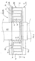
- Figure 2 which is the cross-section AA from Figure 3 , shows a vertical cross-section of a typical pretreatment apparatus 10a or 10b with 5 rings, applied according to the invention.
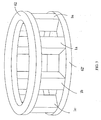
- Figure 3 which is a cross-section BB from Figure 2 , shows a horizontal cross-section of corresponding pretreatment apparatuses 10a or 10b with 7 rings.
- the apparatuses presented in Figure 2 and Figure 3 are comprised of two coaxial rotors 62, 64 fitted inside a housing 26, i.e.
- both rotors 62 and 64 have one more ring equipped with blades than the rotors shown in Figure 2 .
- the first rotor 62 has four rings 1,3,5 and 7 and the rotor 64 three rings 2,4 and 6, on which blades having impact surfaces a', b', c'... have been mounted.
- the cross-section profile of the blades in Figure 2 and Figure 3 is rectangular, and turned so that the impact surfaces of blades are in the radially oriented.
- the impact surface of one or more blades may deviate from the radial orientation.
- the cross-section profile of blades may naturally differ from the rectangular shape, for example, they may be triangular.
- the rotors 62 and 64 may freely rotate in opposite directions.
- the rings 1, 3, 5 and 7, and 2, 4 and 6 of different rotors are staggered as shown in Figure 3 .
- One of the rotors may be a stator.
- the figures do not show any as such known drives needed to rotate the rotors, such as motors, which may be disposed in the housing.
- Figure 3 shows the arrangement of blades 1a, b, c ... and 7a, b, c... of the first rotor 62 with their impact surfaces, and the arrangement of blades 2a, b, c... of the second rotor 64 with their impact surfaces, on rings 1 - 7.
- the rings formed by the impact surfaces are located at a small horizontal distance L from each other. This distance may be the same for all adjacent rings, typically about 2 - 4 mm. On the other hand, the distance L between the rings may decrease in the direction from the centre of the device outwards, for example, the distance may > 3 mm between the inner rings, and ⁇ 1mm between the outer rings.
- the space 25' between the outermost ring 7 and the housing wall 26' forms an open ring-shaped or cylindrical chute that is open towards the rotors, along which chute the pretreated material, which has travelled through the rings 1 - 7, is channelled toward the discharge opening 25 of the housing as shown in Figure 3 . It is possible to connect tangentially a motor-driven discharge screw to the discharge opening, for further transport of the pretreated material.
- the space between the blades, distance S is much smaller at the outer rings 6 and 7 than at the inner rings 1 and 2.
- the distance S may also be the same.
- the solution according to Figure 3 enables large material flows to be fed into the apparatus, containing relatively large, even coarse agglomerates.
- the smaller distance S at the outer rings enables efficient grinding of agglomerates.
- a substantial advantage is achieved when the number of blades and the distances between the rings, i.e. the so-called tightness, can be selected according to the need. It is possible to arrange a decreasing distance between both rings and blades towards the outer rings, whereby the agglomerates or such being fragmented are packed into an increasingly tight space as they flow towards the outer ring, which makes fragmentation more effective.
- Waste and possibly other material is fed to the apparatus via the feed opening 24, which is possible since the rotor axes are nested below the rotors.
- Treated waste is discharged through the tangential opening 25.
- Waste fed into the pretreatment apparatus is thrust outwards from the feeding opening 24, towards the innermost, i.e. the first ring 1 of the first rotor 62, where the waste encounters the impact surfaces a', b', c'... of the ring blades. From these surfaces the waste is centrifuged back with high kinetic energy, and at the same time outwards, towards the first ring 2 of the second rotor 64; colliding with the impact surfaces a', b', c' of the blades rotating in the opposite direction.
- the waste is again centrifuged in the opposite direction, and outwards with high kinetic energy, colliding with the impact surfaces of the second ring 3 of the first rotor 62.
- the waste and any other substances continue their progress in the apparatus colliding in each ring with high kinetic energy with the impact surfaces a', b', c', of the blades of the respective rings.
- Figure 4 presents a modified version of the apparatus presented in Figure, 2 .
- Figure 4 presents an apparatus in which the housing walls 26 are located at a distance from the outermost ring 5 of the rotor, creating a wide space 70 between the rotors and the housing walls, into which, space the waste is flung from the impact surfaces a', b', c'... of the blades of the outermost ring 5.
- Part of the waste can freely fall down to the funnel-shaped bottom 27 of the housing, while part is flung against the housing walls 26' and flows down along the walls towards the discharge opening 27' located in the funnel-shaped bottom.
- the blades 1a, 1b, 1c...1n; 2a, 2b, 2c...2n; 3a, 3b, 3c...3n etc. of each ring 1, 2, 3...n of both rotors 62, 64 are advantageously mounted one the apparatus, as can be seen in the case of the rotor 62 in Figure 5 , in which the blades are mounted not only on the actual rotor parts 62, 64 rotating the blades, but also on the typically ring-shaped 62', 64' support element mainly of the same width as the ring located at the other ends of each ring blade.
- Figure 5 shows the blades 1a, 1b, 1c,...1n of only one ring, which blades are attached by their upper part to the actual rotor part 62, and by their lower part to the support element 62'.
- the actual rotor part 62 is typically several rings wide in the radial direction, and on it are fitted, blades on several rings, as shown in Figures 2 and 3 .
- the support element is only one ring wide so that rotors 62, 64 can be nested. The support elements make the apparatus highly stable and strong.
- the efficiency of the decomposition process according to the invention can be easily be increased by feeding some microbe-containing waste sludge from the actual decomposition apparatus back into the pretreatment apparatus.
- the apparatus useful in the invention is easy to make very strong and durable, in which case the apparatus can receive unscreened waste containing impurities such as glass bottles, and grind them into a very fine material.
Landscapes
- Engineering & Computer Science (AREA)
- Food Science & Technology (AREA)
- Processing Of Solid Wastes (AREA)
- Treatment Of Sludge (AREA)
- Apparatuses For Bulk Treatment Of Fruits And Vegetables And Apparatuses For Preparing Feeds (AREA)
- Organic Low-Molecular-Weight Compounds And Preparation Thereof (AREA)
- Crushing And Pulverization Processes (AREA)
Claims (10)
- Verfahren zum biologischen und/oder chemischen Abbau von Abfall, der organisches Material enthält, wobei das Verfahren umfasst:- Abfallvorbehandlung und- tatsächliche biologische und/oder chemische Abbaubehandlung im Abbaureaktor (12, 14), wobei der Abbau durch Verwendung von anaeroben Bakterien verwirklicht wird,dadurch gekennzeichnet, dass
eine Abfallvorbehandlung ein Bilden eines pumpbaren Schlamms aus Abfall und Abfallfragmentierung und -homogenisierung in einer Vorbehandlungsapparatur (10a, 10b), die auf dem Prinzip einer doppelt wirkenden Multiring-Prallmühle arbeitet, umfasst, welche umfasst:- ein Gehäuse (26), das mit einer Zuführungsöffnung (24) und einer Austragungsöffnung (25, 27') ausgestattet ist,- einen ersten Rotor (62), der im Inneren des Gehäuses angeordnet ist, wobei der Rotor mit Blättern (1a, b, c..., 3a, b, c...) mit Prallflächen (a', b', c',...) ausgestattet ist und wobei die Blätter wenigstens einen oder mehr, typischerweise wenigstens zwei, Ringe (1, 3, 5) bilden, die mit dem Rotor koaxial sind, und- einen Stator, der im Inneren des Gehäuses koaxial mit dem ersten Rotor (62) angeordnet ist, oder einen weiteren Rotor (64), der sich in der entgegengesetzten Richtung dreht, und wobei der Stator oder der andere Rotor mit Blättern (2a, b, c...) ausgestattet sind, die Prallflächen (a', b', c',...) haben, wobei diese Blätter wenigstens einen oder mehr, typischerweise wenigstens zwei, Ringe (2, 4, 6) bilden, die koaxial mit dem Stator oder anderem Rotor montiert sind, und wobei diese Ringe so angeordnet sind, dass sie bezüglich des Rings oder der Ringe des ersten Rotors versetzt sind,wobei der Abfall durch die Zuführungsöffnung (24) der Vorbehandlungsapparatur (10a, 10b) in die Nabe bzw. den Kern der Ringe (1, 2, 3, ...7), gebildet durch die Blätter (1a, b, c, ...2a, b, c, ... 7a, b, c,...), geführt wird, von wo aus der Abfall hergerichtet wird, um durch die Wirkung eines Rotors oder von Rotoren (62, 64) zu dem äußersten Ring des Rings (7), gebildet durch die äußersten Blätter (7a, b, c,...) und außerdem zu der Austragungsöffnung (25, 27') am äußersten Ring zu wandern, und wobei- der pumpbar Schlamm einen Trockensubstanzgehalt von 10-30% hat, wodurch- die notwendige Menge an Flüssigkeit, zum Beispiel Rohwasser, Verfahrenswasser, Abwasser oder Schlamm mit hohem Flüssigkeitsgehalt, zu dem Abfall unter Bildung eines Schlamms gegeben wird, und- der Abfall in der Vorbehandlungsapparatur zu einer geeigneten Partikelgröße, die zur Schlammbildung geeignet ist, fragmentiert wird, typischerweise zu einer Korngröße, bei der mehr als 95% der Partikel unter 5 mm sind, am typischsten so, dass mehr als die Hälfte unter 3 mm sind, und dass- die tatsächliche Abbaubehandlung des Abfalls Verdauung des Schlamms, der in der Vorbehandlungsstufe gebildet wurde, unter Verwendung anaerober Bakterien umfasst, bei der Biogas, das Kohlendioxid und Methangas usw. enthält, als ein Abbauprodukt produziert wird. - verfahren gemäß Anspruch 1, dadurch gekennzeichnet, dass der Abfall aus biologisch abbaubaren Komponenten, die festes Material und/oder Schlamm enthalten, zum Beispiel Gemeinschaftsabfall, Schlamm aus Abwasserreinigungsanlagen, landwirtschaftlicher Abfall, zum Beispiel Abfall aus Viehhaltung und Schlachterabfall, Abfall aus der Fischindustrie, Gartenarbeitsabfall, Abfall aus der Nahrungsmittelindustrie und/oder anderer industrieller Abfall, besteht.
- Verfahren gemäß Anspruch 1, dadurch gekennzeichnet, dass außerdem dem Abfallstrom, der in die Vorbehandlungsapparatur (10a) eintritt und/oder diese verlässt, zugesetzt werden:- Mikroben, die einen biologischen Abbau von Abfall begünstigen, nämlich anaerobe Bakterien und/oder andere Substanz, die Abfallabbau begünstigt, zum Beispiel ein Katalysator oder ein Enzym,- Mikroben enthaltendes Verfahrenswasser, das aus dem Abfall nach Vorbehandlung oder während oder nach tatsächlicher Abbaubehandlung abgetrennt wurde, zu dem Abfallstrom gegeben wird und/oder- Mikroben enthaltender behandelter Abfall, der aus der Vorbehandlungsapparatur oder dem tatsächlichen Abbauverfahren stammt, wobei dieser Abfall zu der Zuführungsöffnung der Vorbehandlungsapparatur zurückgeführt wird.
- Verfahren gemäß Anspruch 1, dadurch gekennzeichnet, dass Luft während des Vorbehandlungsverfahrens, typischerweise unter Verwendung von Stickstoffspülung, aus dem Abfall, der für eine anaerobe Abbaubehandlung vorbehandelt werden soll, entfernt wird.
- Verfahren gemäß Anspruch 1, dadurch gekennzeichnet, dass es die folgenden aufeinanderfolgenden Stufen umfasst, in denen- behandelter Abfall, der aus der ersten Vorbehandlung (10a) ausgetragen wird, in dem tatsächlichen Abbauverfahren (12) unter Verwendung anaerober Bakterien biologisch abgebaut wird, sodass Biogas, das zum Beispiel Methan und Kohlendioxid enthält, produziert wird,- die Flüssigkeit, die für die weitere Behandlung überschüssig ist, von dem festen Material, das aus der Abbaubehandlung (12) übrig bleibt, abgetrennt wird und der verbleibende feste Abfall zu der zweiten Vorbehandlung (10b) transportiert wird, um in der Vorbehandlungsapparatur behandelt zu werden, die auf dem Prinzip einer doppelwirkenden Multiring-Prallmühle arbeitet, und- der vorbehandelte Abfall, der aus der zweiten Vorbehandlungsapparatur (10b) ausgetragen wird, in der zweiten Abbaubehandlung (14) unter Verwendung aerober Bakterien biologisch abgebaut wird oder indem der Abfall in einem Vergasungsreaktor vergast wird, sodass Kohlenmonoxid und Wasserstoff enthaltendes Gas usw. gebildet werden, die als Brennstoff eingesetzt werden können.
- Verfahren gemäß Anspruch 5, dadurch gekennzeichnet, dass der in der ersten Abbaubehandlung behandelte Abfall in der zweiten Vorbehandlungsapparatur behandelt wird,- indem der Abfall zu einer geeigneten Partikelgröße, die für die zweite Abbaubehandlung geeignet ist, zerkleinert wird und- indem der Abfall durch Zusetzen eines Trocknungsmittels, zum Beispiel kleine Äste, Rinde, Späne, Stroh, trockenes Heu oder Torf, in der zweiten Vorbehandlungsapparatur belüftet wird.
- Verfahren gemäß Anspruch 1, dadurch gekennzeichnet, dass das Verfahren Hydrolysieren (43) von Abfall unter Verwendung hydrolysierender Bakterien in einem Hydrolysereaktor zwischen der Vorbehandlung in einer Vorbehandlungsapparatur und dem tatsächlichen Abbau unter Verwendung anaerober Bakterien in einem Abbaureaktor umfasst.
- Verfahren gemäß Anspruch 1, dadurch gekennzeichnet, dass der Abfall zur Vorbehandlung präpariert wird,- indem übergroße metallische oder andere nicht-organische Partikel aus dem Abfall unter Verwendung grober Siebe, eines Metallseparators (20) von Hand oder durch ein anderes geeignetes Verfahren entfernt werden, und/oder- indem die übergroßen Partikel zerkleinert werden.
- Verfahren gemäß Anspruch 1, dadurch gekennzeichnet, dass die Abfallvorbehandlung kontinuierlich ist und dass die Verweilzeit des Abfalls in der Vorbehandlungsapparatur < 10 Sekunden, typischerweise weniger als 5 Sekunden, am typischsten weniger als 1 Sekunde ist.
- Verfahren gemäß Anspruch 1, dadurch gekennzeichnet, dass- Abfall in einer Vorbehandlungsapparatur entweder bei Über- oder Unterdruck vorbehandelt wird und/oder dass- die Temperatur des Abfalls in der Vorbehandlungsapparatur erhöht wird, zum Beispiel indem warme Flüssigkeit oder Dampf dem Abfall zugeführt werden.
Applications Claiming Priority (3)
| Application Number | Priority Date | Filing Date | Title |
|---|---|---|---|
| FI20030058A FI117094B (fi) | 2003-01-15 | 2003-01-15 | Menetelmä orgaanisen jätteen hajottamiseksi |
| FI20030058 | 2003-01-15 | ||
| PCT/FI2003/000983 WO2004062808A1 (en) | 2003-01-15 | 2003-12-29 | Method and device for disintegration of organic material and use of the device |
Publications (2)
| Publication Number | Publication Date |
|---|---|
| EP1583609A1 EP1583609A1 (de) | 2005-10-12 |
| EP1583609B1 true EP1583609B1 (de) | 2012-02-22 |
Family
ID=8565335
Family Applications (1)
| Application Number | Title | Priority Date | Filing Date |
|---|---|---|---|
| EP03767847A Expired - Lifetime EP1583609B1 (de) | 2003-01-15 | 2003-12-29 | Verfahren zur zersetzung von organischem material |
Country Status (6)
| Country | Link |
|---|---|
| US (1) | US7314190B2 (de) |
| EP (1) | EP1583609B1 (de) |
| AT (1) | ATE546227T1 (de) |
| AU (1) | AU2003296037A1 (de) |
| FI (1) | FI117094B (de) |
| WO (1) | WO2004062808A1 (de) |
Families Citing this family (27)
| Publication number | Priority date | Publication date | Assignee | Title |
|---|---|---|---|---|
| US7144507B2 (en) * | 2002-12-11 | 2006-12-05 | Paul Baskis | Dry cycle anaerobic digester |
| US7387733B2 (en) * | 2003-12-11 | 2008-06-17 | Baswood, Llc | System and method for processing organic waste material |
| FI119475B (fi) * | 2004-06-14 | 2008-11-28 | Fractivator Oy | Menetelmä hyötytuotteen valmistamiseksi lietteestä |
| FI117711B (fi) * | 2004-10-13 | 2007-01-31 | Fractivator Oy | Menetelmä ja laitteisto materiaalien tai materiaaliseosten käsittelemiseksi |
| DE102005030980A1 (de) * | 2005-07-02 | 2007-01-04 | Tuchenhagen Dairy Systems Gmbh | Verfahren und Anordnung zur Verbesserung der Gasausbeute in Anlagen zur Erzeugung von Biogas |
| ES2292312B1 (es) * | 2005-09-23 | 2009-02-16 | Universidad De Leon | Un procedimiento para la obtencion de hidrogeno y metano a partir de biorresiduos. |
| WO2008064208A2 (en) * | 2006-11-21 | 2008-05-29 | The Trustees Of Columbia University In The City Of New York | Methods and systems for accelerating the generation of methane from a biomass |
| US8093041B1 (en) | 2007-01-23 | 2012-01-10 | Arrowhead Center, Inc. | Method and apparatus for membrane-based, two-stage gas production from solid biomaterials |
| WO2008092188A1 (en) * | 2007-01-31 | 2008-08-07 | Easternwell Group Holdings Pty Ltd | Wastewater treatment system |
| FI119467B (fi) | 2007-04-10 | 2008-11-28 | Fractivator Oy | Parannettu vastaiskumylly |
| US8158842B2 (en) * | 2007-06-15 | 2012-04-17 | Uop Llc | Production of chemicals from pyrolysis oil |
| US7960520B2 (en) * | 2007-06-15 | 2011-06-14 | Uop Llc | Conversion of lignocellulosic biomass to chemicals and fuels |
| US8013195B2 (en) * | 2007-06-15 | 2011-09-06 | Uop Llc | Enhancing conversion of lignocellulosic biomass |
| US20090221865A1 (en) * | 2008-02-28 | 2009-09-03 | Renaud Regis P | Method and apparatus for injecting enriched steam |
| US8258364B2 (en) * | 2008-06-16 | 2012-09-04 | Renaud Regis P | Method for steam biomass reactor |
| FI120733B (fi) * | 2008-11-14 | 2010-02-15 | Fractivator Oy | Menetelmä ja laite hienojakoisen kalsiumhydroksidin valmistamiseksi |
| IT1393329B1 (it) | 2009-01-21 | 2012-04-20 | Brondolin S P A | Pistone e anello di tenuta per pressofusione |
| FR2942792B1 (fr) * | 2009-03-06 | 2012-06-29 | Otv Sa | Procede d'obtention de boues imputrescibles et d'energie et installation correspondante |
| US8968557B2 (en) | 2011-05-26 | 2015-03-03 | Paul T. Baskis | Method and apparatus for converting coal to petroleum product |
| CA2901416C (en) * | 2013-02-19 | 2020-12-01 | Grains Research & Development Corporation | Weed seed devitalization arrangement |
| CN103553277A (zh) * | 2013-11-14 | 2014-02-05 | 安徽省绿巨人环境技术有限公司 | 一种肉制品加工废水的处理工艺 |
| KR102496146B1 (ko) * | 2014-01-28 | 2023-02-06 | 버크 인스티튜트 포 리서치 온 에이징 | 노화 세포를 사멸시키고 노화 관련 질환 및 장애를 치료하기 위한 방법 및 조성물 |
| CN103965966B (zh) * | 2014-04-23 | 2015-10-21 | 中国华能集团清洁能源技术研究院有限公司 | 一种带有机废水处理的干粉加压气化装置 |
| CA3101758C (en) * | 2015-07-14 | 2023-05-09 | Dean Mayerle | Weed seed destruction with a horizontal transfer member |
| CN106479859B (zh) * | 2016-09-23 | 2017-12-19 | 江苏省农业科学院 | 利用污水对秸秆捆发酵前预处理的装置及其应用 |
| EP4054766B1 (de) * | 2019-11-04 | 2025-06-04 | Moviator Oy | Mühle |
| CN114600651B (zh) * | 2022-03-18 | 2023-01-20 | 苏州科技大学 | 一种绿色农业发展用秸秆回收装置 |
Family Cites Families (11)
| Publication number | Priority date | Publication date | Assignee | Title |
|---|---|---|---|---|
| GB891152A (en) | 1957-11-21 | 1962-03-14 | Peter Willems | A method and apparatus for continuously changing the structure of substances or mixtures of such substances |
| JPS61268344A (ja) * | 1985-01-22 | 1986-11-27 | Funken:Kk | 微粉炭、オイルコ−クス等の粉体をスラリ−化するための連続混練方法及びその装置 |
| ATE59314T1 (de) * | 1986-03-21 | 1991-01-15 | Tallinsk Polt Inst | Desintegrator. |
| AT397959B (de) * | 1991-01-17 | 1994-08-25 | Bertwin Dr Langenecker | Verfahren und vorrichtung zum herstellen von dünger aus gülle und ernterückständen |
| US5846425A (en) * | 1994-07-22 | 1998-12-08 | Whiteman; George R. | Methods for treatment of waste streams |
| DE19541891A1 (de) * | 1995-11-10 | 1997-05-22 | Voith Sulzer Stoffaufbereitung | Vorrichtung zur Behandlung von hochkonsistentem Faserstoff |
| FI105112B (fi) * | 1997-01-03 | 2000-06-15 | Megatrex Oy | Menetelmä ja laite kuitupitoisen materiaalin kuiduttamiseksi |
| JP3270748B2 (ja) | 1999-05-21 | 2002-04-02 | 庄田 賀一 | 生ごみ処理装置 |
| AU2001258789A1 (en) | 2000-05-22 | 2001-12-03 | Nara Machinery Co., Ltd. | Powder processing unit |
| US6811701B2 (en) | 2001-10-24 | 2004-11-02 | University Of Florida Research Foundation, Inc. | Fixed-film anaerobic digestion of flushed manure |
| KR20030074966A (ko) | 2002-03-15 | 2003-09-22 | 주식회사 태영 | 슬러지 전처리 및 고농도 막분리 생물반응조를 이용한슬러지 처리방법 |
-
2003
- 2003-01-15 FI FI20030058A patent/FI117094B/fi not_active IP Right Cessation
- 2003-12-29 AU AU2003296037A patent/AU2003296037A1/en not_active Abandoned
- 2003-12-29 EP EP03767847A patent/EP1583609B1/de not_active Expired - Lifetime
- 2003-12-29 US US10/534,085 patent/US7314190B2/en not_active Expired - Fee Related
- 2003-12-29 WO PCT/FI2003/000983 patent/WO2004062808A1/en not_active Ceased
- 2003-12-29 AT AT03767847T patent/ATE546227T1/de active
Also Published As
| Publication number | Publication date |
|---|---|
| WO2004062808A1 (en) | 2004-07-29 |
| EP1583609A1 (de) | 2005-10-12 |
| AU2003296037A1 (en) | 2004-08-10 |
| US7314190B2 (en) | 2008-01-01 |
| FI117094B (fi) | 2006-06-15 |
| FI20030058L (fi) | 2004-07-16 |
| FI20030058A0 (fi) | 2003-01-15 |
| ATE546227T1 (de) | 2012-03-15 |
| US20060011757A1 (en) | 2006-01-19 |
Similar Documents
| Publication | Publication Date | Title |
|---|---|---|
| EP1583609B1 (de) | Verfahren zur zersetzung von organischem material | |
| CN101508603B (zh) | 一种高速堆肥法及装置 | |
| JPH11504561A (ja) | 廃水スラッジの濃縮および輸送のための装置および方法 | |
| KR20060059919A (ko) | 남은음식물류쓰레기의 혐기성자원화를 위한 밀링식 분쇄 및원심식 고액분리 연속처리공정구성과 탈리액의 효소반응을이용한 전처리공정의 설비구성 및 그 운영 방안. | |
| CN104203872A (zh) | 一种用于家庭有机废物的改进的厌氧消化系统 | |
| KR101734153B1 (ko) | 디스크 건조기를 이용하는 음식물류폐기물 처리 시스템 | |
| CN216764745U (zh) | 一种蓝藻混合有机废弃物智能高温好氧发酵系统 | |
| KR20100122622A (ko) | 석회처리 비료 제조장치 및 방법 | |
| KR100426976B1 (ko) | 음식물쓰레기 전처리시스템 | |
| KR101327185B1 (ko) | 유기성 폐기물 및 슬러지를 이용한 부숙토 제조 방법 및 이의 방법에 의해 제조된 부숙토 | |
| JP2001191059A (ja) | 発酵処理方法およびセメント製造方法 | |
| FI130365B (en) | A method for treating biosludge | |
| CN218202578U (zh) | 一种生物质垃圾资源转化设备 | |
| CN112939649A (zh) | 一种集成式一体化湿垃圾原位资源化处理系统和处理方法 | |
| CN118926272A (zh) | 一种湿垃圾水热反应制黄腐酸的工艺 | |
| KR200425442Y1 (ko) | 밀링식 분쇄와 원심식 고액분리 연속처리 및 탈리액의 효소반응을 이용한 음식쓰레기의 전처리 설비 | |
| CN216273827U (zh) | 一种基于干法厌氧沼渣三级脱水的粉肥制作系统 | |
| CN215403931U (zh) | 一种区域有机废弃物协同处理系统 | |
| KR101663082B1 (ko) | 음식물 쓰레기와 하수 슬러지를 이용한 유기질 비료 및 발효 액상 비료 제조 장치 및 이를 이용한 유기질 비료 및 발효 액상 비료 제조 방법 | |
| KR102845727B1 (ko) | 유기성 폐자원 및 생분해 플라스틱 분해방법 | |
| CN220012500U (zh) | 一种餐厨垃圾厌氧沼渣无害化处理设备 | |
| EP1557403B1 (de) | System und Verfahren zur kompostierungsfreien Entsorgung der organischen Abfälle | |
| CN113105276A (zh) | 蔬菜垃圾处置资源化利用生产工艺及其装置 | |
| CN217459282U (zh) | 一种有机固体废弃物处理装置 | |
| CN108251284B (zh) | 一种微生物硝化法分解固体有机物废弃物的设备 |
Legal Events
| Date | Code | Title | Description |
|---|---|---|---|
| PUAI | Public reference made under article 153(3) epc to a published international application that has entered the european phase |
Free format text: ORIGINAL CODE: 0009012 |
|
| 17P | Request for examination filed |
Effective date: 20050617 |
|
| AK | Designated contracting states |
Kind code of ref document: A1 Designated state(s): AT BE BG CH CY CZ DE DK EE ES FI FR GB GR HU IE IT LI LU MC NL PT RO SE SI SK TR |
|
| AX | Request for extension of the european patent |
Extension state: AL LT LV MK |
|
| DAX | Request for extension of the european patent (deleted) | ||
| 17Q | First examination report despatched |
Effective date: 20090330 |
|
| REG | Reference to a national code |
Ref country code: DE Ref legal event code: R079 Ref document number: 60340086 Country of ref document: DE Free format text: PREVIOUS MAIN CLASS: B02C0013220000 Ipc: B02C0013200000 |
|
| GRAP | Despatch of communication of intention to grant a patent |
Free format text: ORIGINAL CODE: EPIDOSNIGR1 |
|
| RIC1 | Information provided on ipc code assigned before grant |
Ipc: B02C 13/22 20060101ALI20110920BHEP Ipc: B02C 13/20 20060101AFI20110920BHEP |
|
| RTI1 | Title (correction) |
Free format text: METHOD FOR DECOMPOSING OF ORGANIC MATERIAL |
|
| RAP1 | Party data changed (applicant data changed or rights of an application transferred) |
Owner name: FRACTIVATOR OY |
|
| GRAS | Grant fee paid |
Free format text: ORIGINAL CODE: EPIDOSNIGR3 |
|
| GRAA | (expected) grant |
Free format text: ORIGINAL CODE: 0009210 |
|
| AK | Designated contracting states |
Kind code of ref document: B1 Designated state(s): AT BE BG CH CY CZ DE DK EE ES FI FR GB GR HU IE IT LI LU MC NL PT RO SE SI SK TR |
|
| REG | Reference to a national code |
Ref country code: GB Ref legal event code: FG4D |
|
| REG | Reference to a national code |
Ref country code: CH Ref legal event code: EP |
|
| REG | Reference to a national code |
Ref country code: AT Ref legal event code: REF Ref document number: 546227 Country of ref document: AT Kind code of ref document: T Effective date: 20120315 |
|
| REG | Reference to a national code |
Ref country code: IE Ref legal event code: FG4D |
|
| REG | Reference to a national code |
Ref country code: DE Ref legal event code: R096 Ref document number: 60340086 Country of ref document: DE Effective date: 20120419 |
|
| REG | Reference to a national code |
Ref country code: NL Ref legal event code: VDEP Effective date: 20120222 |
|
| PG25 | Lapsed in a contracting state [announced via postgrant information from national office to epo] |
Ref country code: NL Free format text: LAPSE BECAUSE OF FAILURE TO SUBMIT A TRANSLATION OF THE DESCRIPTION OR TO PAY THE FEE WITHIN THE PRESCRIBED TIME-LIMIT Effective date: 20120222 |
|
| PG25 | Lapsed in a contracting state [announced via postgrant information from national office to epo] |
Ref country code: FI Free format text: LAPSE BECAUSE OF FAILURE TO SUBMIT A TRANSLATION OF THE DESCRIPTION OR TO PAY THE FEE WITHIN THE PRESCRIBED TIME-LIMIT Effective date: 20120222 Ref country code: GR Free format text: LAPSE BECAUSE OF FAILURE TO SUBMIT A TRANSLATION OF THE DESCRIPTION OR TO PAY THE FEE WITHIN THE PRESCRIBED TIME-LIMIT Effective date: 20120523 Ref country code: PT Free format text: LAPSE BECAUSE OF FAILURE TO SUBMIT A TRANSLATION OF THE DESCRIPTION OR TO PAY THE FEE WITHIN THE PRESCRIBED TIME-LIMIT Effective date: 20120622 Ref country code: BE Free format text: LAPSE BECAUSE OF FAILURE TO SUBMIT A TRANSLATION OF THE DESCRIPTION OR TO PAY THE FEE WITHIN THE PRESCRIBED TIME-LIMIT Effective date: 20120222 |
|
| REG | Reference to a national code |
Ref country code: AT Ref legal event code: MK05 Ref document number: 546227 Country of ref document: AT Kind code of ref document: T Effective date: 20120222 |
|
| PG25 | Lapsed in a contracting state [announced via postgrant information from national office to epo] |
Ref country code: CY Free format text: LAPSE BECAUSE OF FAILURE TO SUBMIT A TRANSLATION OF THE DESCRIPTION OR TO PAY THE FEE WITHIN THE PRESCRIBED TIME-LIMIT Effective date: 20120222 |
|
| PG25 | Lapsed in a contracting state [announced via postgrant information from national office to epo] |
Ref country code: SE Free format text: LAPSE BECAUSE OF FAILURE TO SUBMIT A TRANSLATION OF THE DESCRIPTION OR TO PAY THE FEE WITHIN THE PRESCRIBED TIME-LIMIT Effective date: 20120222 Ref country code: CZ Free format text: LAPSE BECAUSE OF FAILURE TO SUBMIT A TRANSLATION OF THE DESCRIPTION OR TO PAY THE FEE WITHIN THE PRESCRIBED TIME-LIMIT Effective date: 20120222 Ref country code: SI Free format text: LAPSE BECAUSE OF FAILURE TO SUBMIT A TRANSLATION OF THE DESCRIPTION OR TO PAY THE FEE WITHIN THE PRESCRIBED TIME-LIMIT Effective date: 20120222 Ref country code: DK Free format text: LAPSE BECAUSE OF FAILURE TO SUBMIT A TRANSLATION OF THE DESCRIPTION OR TO PAY THE FEE WITHIN THE PRESCRIBED TIME-LIMIT Effective date: 20120222 Ref country code: EE Free format text: LAPSE BECAUSE OF FAILURE TO SUBMIT A TRANSLATION OF THE DESCRIPTION OR TO PAY THE FEE WITHIN THE PRESCRIBED TIME-LIMIT Effective date: 20120222 Ref country code: RO Free format text: LAPSE BECAUSE OF FAILURE TO SUBMIT A TRANSLATION OF THE DESCRIPTION OR TO PAY THE FEE WITHIN THE PRESCRIBED TIME-LIMIT Effective date: 20120222 |
|
| PG25 | Lapsed in a contracting state [announced via postgrant information from national office to epo] |
Ref country code: IT Free format text: LAPSE BECAUSE OF FAILURE TO SUBMIT A TRANSLATION OF THE DESCRIPTION OR TO PAY THE FEE WITHIN THE PRESCRIBED TIME-LIMIT Effective date: 20120222 Ref country code: SK Free format text: LAPSE BECAUSE OF FAILURE TO SUBMIT A TRANSLATION OF THE DESCRIPTION OR TO PAY THE FEE WITHIN THE PRESCRIBED TIME-LIMIT Effective date: 20120222 |
|
| PLBE | No opposition filed within time limit |
Free format text: ORIGINAL CODE: 0009261 |
|
| STAA | Information on the status of an ep patent application or granted ep patent |
Free format text: STATUS: NO OPPOSITION FILED WITHIN TIME LIMIT |
|
| 26N | No opposition filed |
Effective date: 20121123 |
|
| PG25 | Lapsed in a contracting state [announced via postgrant information from national office to epo] |
Ref country code: AT Free format text: LAPSE BECAUSE OF FAILURE TO SUBMIT A TRANSLATION OF THE DESCRIPTION OR TO PAY THE FEE WITHIN THE PRESCRIBED TIME-LIMIT Effective date: 20120222 |
|
| REG | Reference to a national code |
Ref country code: DE Ref legal event code: R097 Ref document number: 60340086 Country of ref document: DE Effective date: 20121123 |
|
| PG25 | Lapsed in a contracting state [announced via postgrant information from national office to epo] |
Ref country code: ES Free format text: LAPSE BECAUSE OF FAILURE TO SUBMIT A TRANSLATION OF THE DESCRIPTION OR TO PAY THE FEE WITHIN THE PRESCRIBED TIME-LIMIT Effective date: 20120602 |
|
| PG25 | Lapsed in a contracting state [announced via postgrant information from national office to epo] |
Ref country code: BG Free format text: LAPSE BECAUSE OF FAILURE TO SUBMIT A TRANSLATION OF THE DESCRIPTION OR TO PAY THE FEE WITHIN THE PRESCRIBED TIME-LIMIT Effective date: 20120522 Ref country code: MC Free format text: LAPSE BECAUSE OF NON-PAYMENT OF DUE FEES Effective date: 20121231 |
|
| REG | Reference to a national code |
Ref country code: CH Ref legal event code: PL |
|
| GBPC | Gb: european patent ceased through non-payment of renewal fee |
Effective date: 20121229 |
|
| REG | Reference to a national code |
Ref country code: IE Ref legal event code: MM4A |
|
| REG | Reference to a national code |
Ref country code: FR Ref legal event code: ST Effective date: 20130830 |
|
| PG25 | Lapsed in a contracting state [announced via postgrant information from national office to epo] |
Ref country code: LI Free format text: LAPSE BECAUSE OF NON-PAYMENT OF DUE FEES Effective date: 20121231 Ref country code: IE Free format text: LAPSE BECAUSE OF NON-PAYMENT OF DUE FEES Effective date: 20121229 Ref country code: CH Free format text: LAPSE BECAUSE OF NON-PAYMENT OF DUE FEES Effective date: 20121231 |
|
| PG25 | Lapsed in a contracting state [announced via postgrant information from national office to epo] |
Ref country code: FR Free format text: LAPSE BECAUSE OF NON-PAYMENT OF DUE FEES Effective date: 20130102 Ref country code: GB Free format text: LAPSE BECAUSE OF NON-PAYMENT OF DUE FEES Effective date: 20121229 |
|
| PG25 | Lapsed in a contracting state [announced via postgrant information from national office to epo] |
Ref country code: TR Free format text: LAPSE BECAUSE OF FAILURE TO SUBMIT A TRANSLATION OF THE DESCRIPTION OR TO PAY THE FEE WITHIN THE PRESCRIBED TIME-LIMIT Effective date: 20120222 |
|
| PG25 | Lapsed in a contracting state [announced via postgrant information from national office to epo] |
Ref country code: LU Free format text: LAPSE BECAUSE OF NON-PAYMENT OF DUE FEES Effective date: 20121229 |
|
| PG25 | Lapsed in a contracting state [announced via postgrant information from national office to epo] |
Ref country code: HU Free format text: LAPSE BECAUSE OF FAILURE TO SUBMIT A TRANSLATION OF THE DESCRIPTION OR TO PAY THE FEE WITHIN THE PRESCRIBED TIME-LIMIT Effective date: 20031229 |
|
| PGFP | Annual fee paid to national office [announced via postgrant information from national office to epo] |
Ref country code: DE Payment date: 20191219 Year of fee payment: 17 |
|
| REG | Reference to a national code |
Ref country code: DE Ref legal event code: R119 Ref document number: 60340086 Country of ref document: DE |
|
| PG25 | Lapsed in a contracting state [announced via postgrant information from national office to epo] |
Ref country code: DE Free format text: LAPSE BECAUSE OF NON-PAYMENT OF DUE FEES Effective date: 20210701 |