EP1582932A2 - Alignment apparatus, exposure apparatus, and device manufacturing method - Google Patents
Alignment apparatus, exposure apparatus, and device manufacturing method Download PDFInfo
- Publication number
- EP1582932A2 EP1582932A2 EP05251985A EP05251985A EP1582932A2 EP 1582932 A2 EP1582932 A2 EP 1582932A2 EP 05251985 A EP05251985 A EP 05251985A EP 05251985 A EP05251985 A EP 05251985A EP 1582932 A2 EP1582932 A2 EP 1582932A2
- Authority
- EP
- European Patent Office
- Prior art keywords
- movable elements
- movable
- support moving
- regulators
- area
- Prior art date
- Legal status (The legal status is an assumption and is not a legal conclusion. Google has not performed a legal analysis and makes no representation as to the accuracy of the status listed.)
- Withdrawn
Links
Images
























Classifications
-
- G—PHYSICS
- G03—PHOTOGRAPHY; CINEMATOGRAPHY; ANALOGOUS TECHNIQUES USING WAVES OTHER THAN OPTICAL WAVES; ELECTROGRAPHY; HOLOGRAPHY
- G03F—PHOTOMECHANICAL PRODUCTION OF TEXTURED OR PATTERNED SURFACES, e.g. FOR PRINTING, FOR PROCESSING OF SEMICONDUCTOR DEVICES; MATERIALS THEREFOR; ORIGINALS THEREFOR; APPARATUS SPECIALLY ADAPTED THEREFOR
- G03F7/00—Photomechanical, e.g. photolithographic, production of textured or patterned surfaces, e.g. printing surfaces; Materials therefor, e.g. comprising photoresists; Apparatus specially adapted therefor
- G03F7/70—Microphotolithographic exposure; Apparatus therefor
- G03F7/70691—Handling of masks or workpieces
- G03F7/70733—Handling masks and workpieces, e.g. exchange of workpiece or mask, transport of workpiece or mask
Definitions
- the present invention relates to an alignment apparatus having two movable elements which move on a plane, an exposure apparatus to which the alignment apparatus is applied, and a device manufacturing method which uses the exposure apparatus.
- Fig. 52 is a plan view of a stage device disclosed in Japanese Patent Laid-Open No. 2003-257851.
- This stage device has a planer motor including a stator 10 having stationary magnets (not shown) and a movable element 17 having movable coils (not shown).
- the movable element 17 moves in X and Y directions within a plane on the stator 10.
- the movable element 17 can rotate with respect to the stator 10 because no guide is provided. If the amount of rotation of the movable element 17 increases, the movable element 17 goes out of control. For this reason, a mechanism that prevents rotation of the movable element 17 is necessary.
- An anti-rotation mechanism or rotation prevention mechanism 100 has an actuator 36 which moves in the Y direction along a guide 52 and a bar 110 which is attached to the support bar 36.
- a sleeve 120 which is arranged to partially surround the bar 110 is attached to the movable element 17. The sleeve 120 can slide along the bar 110.
- the movable element 17 moves in the X direction, the sleeve 120 slides along the bar 110.
- the actuator 36 also moves in the Y direction by a corresponding amount.
- the movable element 17 can move freely without being interfered with by the anti-rotation mechanism 100. Even if the movable element 17 is to rotate about the Z-axis, it cannot rotate because the two ends of the sleeve 120 are in contact with the bar 110.
- Cables 37 for supplying power to the coils or the like of the movable element 17 are provided between the movable element 17 and actuator 36.
- the actuator 36 When the movable element 17 moves in the Y direction, the actuator 36 also moves accordingly.
- the loop shapes of the cables 37 do not change, and the movable element 17 receives no load change from the cables 37.
- the anti-rotation mechanism 100 is provided with encoders 125 and 127 which are used for alignment adjustment of the movable element 17 and the like.
- An embodiment of the present invention seeks to prevent, for example, in an alignment apparatus having two movable elements which move on a stator having a planer portion, the two movable elements from moving to deviate from target positions while enabling swap of the two movable elements.
- An alignment apparatus comprises a stator which has a planer portion including first and second areas, first and second movable elements which move on the planer portion, and a regulating mechanism which regulates positions of the first and second movable elements.
- the first and second movable elements are driven to target positions by a force that acts among the first and second movable elements and stator.
- the regulating mechanism includes a first regulator which regulates the position of, of the first and second movable elements, one which is located in the first area such that the movable element will not deviate from the target position, and a second regulator which regulates the position of, of the first and second movable elements, one which is located in the second area such that the movable element will not deviate from the target position.
- the first and second areas can partially overlap.
- the first and second regulators do not come into contact with the first and second movable elements while the first and second movable elements are located at the target positions.
- the first and second movable elements respectively include engaging portions, and deviation of the movable elements from the target positions is regulated by contact of the first or second regulator and the engaging portions.
- the regulating mechanism includes a driving mechanism which moves the engaging portions and/or the first and second regulators when the first and second movable elements are to be swapped between the first and second areas.
- the first and second movable elements can respectively include at least first and second engaging portions, the position of the movable element which has been driven from the second area to the first area can be regulated by the first engaging portion and first regulator, and the position of the movable element which has been driven from the first area to the second area can be regulated by the second engaging portion and second regulator.
- the engaging portions can include recesses, ridges, or holes.
- the first regulator can be provided to a first support moving member which moves together with, of the first and second movable elements, one which is located in the first area
- the second regulator can be provided to a second support moving member which moves together with, of the first and second movable elements, one which is located in the second area.
- the first and second support moving members can move in such directions that a distance between the first and second support moving members changes.
- the first and second regulators extend along, e.g., longitudinal directions of the first and second support moving members, respectively, and the first and second support moving members stop when, e.g., the first and second movable elements move along the longitudinal directions, and move in the longitudinal directions, when the first and second movable elements move along directions perpendicular to the longitudinal directions, together with the first and second movable elements.
- the first regulator may move in the longitudinal direction of the first support moving member together with the movable element located in the first area
- the second regulator may move along the longitudinal direction of the second support moving member together with the movable element located in the second area.
- the first and second support moving members have stoppers which regulate moving ranges of the first and second movable elements in the longitudinal directions.
- the alignment apparatus comprises a second stopper which regulates moving ranges of the first and second support moving members.
- the alignment apparatus further comprises a first support moving member which is arranged to extend along a second direction perpendicular to a first direction and moves along the first direction together with, of the first and second movable elements, one which is located in the first area, a second support moving member which is arranged to extend along the second direction and moves together with, of the first and second movable elements, one which is located in the second area, a first fixed member which is arranged within the first area so as to extend along the first direction between the first and second support moving members, and a second fixed member which is arranged within the second area so as to extend along the first direction between the first and second support moving members.
- the first regulator can be provided to the first support moving member and first fixed member to regulate the position of the movable element in the first area
- the second regulator can be provided to the second support moving member and second fixed member to regulate the position of the movable element in the second area.
- a portion through which the first and second regulators and the engaging portions can be in contact with each other is formed such that when the engaging portions come into contact with the first and second regulators, the engaging portions slide on the first and second regulators.
- the first and second regulators and the engaging portions come into contact with each other through rollers.
- each of the first and second regulators is divided into a plurality of pieces, and the plurality of divisional pieces are driven independently of each other.
- the first and second regulators and the first and second movable elements are formed such that even when a power supply is turned off, the positions of the first and second movable elements are regulated by the first and second regulators.
- At least one of the first and second movable elements has an identifying unit for identifying the remaining one of the first and second movable elements.
- the alignment apparatus further comprises a sensor which checks that the positions of the first and second movable elements are regulated by the first and second regulators.
- the first and second movable elements arranged on a line along a first direction are moved in opposite directions along a second direction perpendicular to the first direction, subsequently, in a second step, the first and second movable elements are moved in opposite directions along the first direction, and subsequently, in a third step, the first and second movable elements are moved in the opposite directions along the second direction so that the first and second movable elements are arranged on the line again, thereby swapping the first and second movable elements.
- the alignment apparatus further comprises first and second support moving members which extend in the second direction and oppose each other, the first and second regulators being provided to the first and second support moving members, respectively, wherein in the first step, while the first and second support moving members are set still, the first and second movable elements are moved along the second direction while regulating the positions of the first and second movable elements by the first and second regulators, in the second step, the first and second support moving members are moved along the first direction and the first and second movable elements are moved along the second direction while regulating the positions of the first and second movable elements by the first and second regulators, and in the third step, while the first and second support moving members are set still, the first and second movable elements are moved along the second direction while regulating the positions of the first and second movable elements by the first and second regulators.
- the first and second movable elements are moved along the first direction to positions where the first and second movable elements are arranged on a line along the second direction, and when the second step is to shift to the third step, the first and second regulators that are to regulate the positions of the first and second movable elements can be swapped.
- the alignment apparatus further comprises first and second support moving members which extend in the second direction and oppose each other, and first and second fixed members arranged between the first and second support moving members along the first direction, wherein the first regulator can be provided to the first support moving member and first fixed member, and the second regulator can be provided to the second support moving member and second fixed member.
- the first and second movable elements can be moved along the second direction while regulating the positions of the first and second movable elements by the first and second regulators provided to the first and second support moving members
- the first and second support moving members can be moved along the first direction
- the first and second movable elements can be moved along the first direction while regulating the positions of the first and second movable elements by the first and second regulators provided to the first and second support moving members
- the first and second moving members can be set still
- the first and second movable elements can be moved along the first direction while regulating the positions of the first and second movable elements by the first and second regulators provided to the first and second fixed members
- the first and second support moving members are set still
- the first and second movable elements can be moved along the second direction while regulating the positions of the first and second movable elements by the first and second regulators provided to the first and second support moving members.
- An exposure apparatus is directed to an exposure apparatus for forming a latent image of a pattern on a photo sensitive agent on a substrate to which the photo sensitive agent has been applied.
- the exposure apparatus comprises the above alignment apparatus which has first and second stages and holds and aligns substrates on the first and second stages, and a pattern forming unit which forms a latent image pattern on the photo sensitive agent on the substrate held on, of the first and second stages, one which is located within an exposure process area, the first and second movable elements including the first and second stages, respectively.
- a device manufacturing method comprises a step of forming, by using the above exposure apparatus, a latent image on a photo sensitive agent on a substrate to which the photo sensitive agent has been applied, and a step of developing the latent image pattern.
- the two movable elements can be prevented from moving to deviate from target positions while enabling swap of the two movable elements.
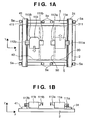
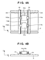
- Figs. 1A to 6B are schematic views of a wafer stage device according to the first embodiment of the present invention.
- Figs. 1A to 6B Figs. 1A, 2A, 3A, 4A, 5A, and 6A are plan views and Figs. 1B, 2B, 3B, 4B, 5B, and 6B are side views.
- Figs. 1A to 6B show the movement of the stages at different steps sequentially.
- the wafer stage device has a twin stage arrangement including two stages (tables). More specifically, the wafer stage device has a stator 2 including fixed coils (not shown) and having a planer portion, and two movable elements 11a and 11b including movable magnets (not shown) which move on the planer potion.
- the two movable elements 11a and 11B respectively include stages (tables) 11a and 11b which can hold wafers, respectively.
- the stator 2 and movable element 11a form one planer motor
- the stator 2 and movable element 11b form the other planer motor.
- each planer motor drives the movable elements 11a and 11b to target positions (or drive them along target trajectories) by the Lorentz force.
- each planer motor has a simple structure as opposed to an arrangement in which a movable element is two-dimensionally driven by a two-axis linear motor.
- the planer motors are not limited to those utilizing the Lorentz force but can be formed by other schemes, e.g., a linear pulse motor which uses a variable magnetoresistance (magnetic attracting force).
- the moving areas of the movable elements 11a and 11b on the stator 2 include an exposure process area 30, an alignment process area 40, and a swap process area 50 sandwiched by the exposure process area 30 and alignment process area 40.
- the two movable elements 11a and 11b can come and go to and from the exposure process area 30 and alignment process area 40 through the swap process area 50.
- Bar mirrors (not shown) are mounted on the two movable elements 11a and 11b. The positions of the bar mirrors are measured by interferometers. The movable elements 11a and 11b are driven to the target positions on the basis of the measurement results.
- Anti-rotation member or rotation prevention member (from another point of view, abnormal movement prevention member,; this applies to the following description) 111a and 112a and 111b and 112b are arranged on the side surfaces of the movable elements 11a and 11b.
- the anti-rotation members 111a and 112a, and 111b and 112b have recesses (engaging portions) and can be vertically moved independently of each other with respect to the movable elements 11a and 11b.
- Support bars (support moving members) 31 and 41 are arranged such that they can be moved by a driving mechanism (not shown) in the X direction along guides 5.
- a driving mechanism for example, magnets can be provided to the support bars 31 and 41, and the support bars 31 and 41 can be driven by the interaction (Lorentz force) with the stator 2.
- the support bars 31 and 41 respectively have ridges (regulating portions) 311 and 411, and can respectively engage with the recesses of the anti-rotation members 111a and 112a of the movable elements 11a and 11b in a noncontact manner. Engagement in a noncontact manner means the following positional relationship.
- the engaging portions in this case, the recesses of the anti-rotation members
- the regulating portions in this case, the ridges formed on the support bars
- the anti-rotation member 111a moves vertically with respect to the movable element 11a.
- a recess 111aa of the anti-rotation member 111a engages with the ridge 311 of the support bar 31 in a noncontact manner.
- the position of the support bar is measured by an interferometer and controlled, so that it can move in synchronism with the movable element while maintaining the non-contact state of the recess (engaging portion) and ridge (regulating portion).
- the support bar 31 also moves in the X direction by a corresponding amount, so the recess 111aa and support bar ridge 311 do not come into contact with each other.
- the recess 111aa can come into contact with the support bar ridge 311 to regulate the movement of the movable element 11a.
- the ridges of the support bars 31 and 41 are regulated such that the support bars 31 and 41 are not rotated by the guides 5, the rotation and X-direction translation of the movable elements 11a and 11b are regulated, but the movable elements 11a and 11b can translate freely in the Y direction.
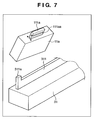
- the support bars 31 and 41 serve as the Y-direction stoppers for the movable elements 11a and 11b, preferably, for example, the end (e.g., the end of the ridge 311) of each of the support bars 31 and 41 may be formed like an end 311a of Fig. 7, so the anti-rotation member 111a collides against the end 311a.
- the stoppers are not limited to this structure, but, e.g., shock absorbers may be provided.
- shock absorbers 5a are preferably provided as the X-direction stoppers to the two ends in the X-direction stroke of each of the support bars 31 and 41, as shown in Fig. 1A.
- the movable elements 11a and 11b rotate and the edges of the recesses of the anti-rotation members 111a, 112a, 111b, and 112b collide against the ridges of the support bars 31 and 41. Then, the recesses of the anti-rotation members 111a and 112a, and 111b and 112b are to slide in the Y direction along the ridges of the support bars 31 and 41. Accordingly, the recesses and ridges may undesirably be broken, dragged, or worn.
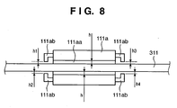
- Fig. 8 is a detailed plan view showing a state wherein the recess 111aa of the anti-rotation member 111a and the ridge 311 of the support bar 31 engage with each other in a non-contact state.
- stoppers 111ab are provided to the two sides of the anti-rotation member 111a.
- the stoppers 111ab serve as engaging portions in place of the inner surface of the recess 111aa.
- the stoppers 111ab preferably have shock absorbing properties and/or are made of a material having a low coefficient of friction (a material having a sufficiently low coefficient of friction so that the stoppers can slide on the ridge).
- Gaps h1 to h4 between the stoppers 111ab and the ridge 311 of the support bar 31 are each smaller than a gap h between the recess 111aa of the anti-rotation member 111a and the ridge 311 of the support bar 31. Hence, the recess 111aa of the anti-rotation member 111a and the ridge 311 of the support bar 31 do not collide against each other or are not dragged by each other.
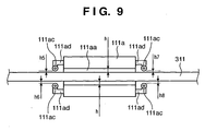
- Fig. 9 shows an example in which bearings (rollers) 111ac are provided in place of the stoppers 111ab of Fig. 8.
- Each bearing 111ac has an outer ring and inner ring, and the inner ring is fixed to the anti-rotation member 111a through a support member 111ad in Fig. 9 so that the outer ring can roll in the transverse direction.
- the outer ring of the bearing serves as an engaging portion in place of the inner surface of the recess 111aa.
- Gaps h5 to h8 between the outer rings of the bearings 111ac and the ridge 311 of the support bar 31 are each smaller than the gap h between the recess 111aa of the anti-rotation member 111a and the ridge 311 of the support bar 31. Hence, the anti-rotation member recess 111aa and the support bar ridge 311 do not collide against each other or are not dragged by each other.
- C-chamfered portions 11bb are formed as identifying units on the movable element 11b.
- Sensors (not shown) for discriminating the presence/absence of the C-chamfered portions 11bb are arranged on the support bars 31 and 41 and can identify which movable element engages with which support bar. This is due to the following reason. For example, if the deformation of the bar mirrors mounted on the movable elements differs between the two movable elements, correction of position control by the interferometers during exposure differs between the two movable elements. Assume that the movable elements (stages) run uncontrollably and that the interferometers are reset. If which movable element engages with which support bar is not known, appropriate correction cannot be performed.
- the identifying units of the movable elements are not limited to the C-chamfered portions 11bb. For example, identification marks having different patterns may be respectively formed on the two movable elements, and the patterns may be read by optical sensors.
- Figs. 1A to 6B The movement of the wafer stage device, particularly, the two movable elements (stages) and support bars, will be described with reference to Figs. 1A to 6B.
- the wafer (substrate) held on the movable element 11a including the stage by a vacuum chuck or the like has been exposed in the exposure process area 30, and the wafer on the movable element 11b including the stage has been alignment-adjusted in the alignment process area 40 in a parallel manner.
- the recess (engaging portion) of the anti-rotation member 111a engages with the ridge (regulating portion) 311 of the support bar 31 in a noncontact manner
- the recess (engaging portion) of the anti-rotation member 112b engages with the ridge (regulating portion) 411 of the support bar 41 in a noncontact manner.
- the hatched anti-rotation members are at the lower positions (at heights where engagement in a noncontact manner is possible), as shown in Fig. 1B, and engage with the ridges of the support bars in a noncontact manner.
- the two movable elements 11a and 11b start swapping.
- the movable elements 11a and 11b start moving in directions of arrows.
- the movable element 11a ends moving in the +Y direction and starts moving in the -X direction.
- the support bar 31 also starts moving in the -X direction.
- the movable element 11b ends moving in the -Y direction and starts moving in the +X direction.
- the support bar 41 also starts moving in the +X direction.
- Fig. 3A shows a state wherein the movable elements 11a and 11b have moved to the swap process area 50.
- the movable elements 11a and 11b and the support bars 31 and 41 stop temporarily.
- the anti-rotation members 111a and 112b move upward to the upper positions (at heights where the anti-rotation members are not regulated by the ridges of the support bars), and the anti-rotation members 111b and 112a move downward to the lower positions.
- the movable elements 11a and 11b swap.
- the movable element 11a is to move together with the support bar 41
- the movable element 11b is to move together with the support bar 31.
- the area where the position of the movable element can be regulated by the ridge 311 formed on the support bar 31 is the first area
- the area where the position of the movable element can be regulated by the ridge 411 formed on the support bar 41 is the second area.
- the position of the movable element located in the first area is regulated by the ridge 311 formed on the support bar 31 so that the movable element will not deviate from the target position.
- the position of the movable element located in the second area is regulated by the ridge 411 formed on the support bar 41 so that the movable element will not deviate from the target position.
- Fig. 5A shows a state wherein the movable element 11a has moved to the alignment process area 40 and the movable element 11b has moved to the exposure process area 30.
- the support bars 31 and 41 have also moved accordingly.
- the movable elements 11a and 11b move in directions of arrows as shown in Fig. 6A, they are restored to the state of Fig. 1A (note that the two movable elements have swapped).
- the exposed wafer is exchanged at, e.g., the position of the movable element 11a in Fig. 5A, for a new wafer by a robot hand.
- one cycle is ended.
- the recesses (engaging portions) of the anti-rotation members and the ridges (regulating portions) of the support bars always engage with each other somewhere in a noncontact manner.
- This embodiment is of a type in which the recesses of the anti-rotation members move vertically.
- the recesses of the anti-rotation members move downward to the lower positions to engage with the ridges of the support bars. The postures of the movable elements will not be largely changed at any time because the movable elements run uncontrollably to lead to an uncontrollable error.
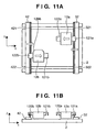
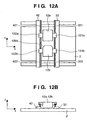
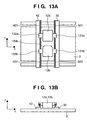
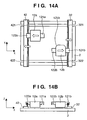
- Figs. 10A to 15B are schematic views of a wafer stage device according to the second embodiment of the present invention.
- Figs. 10A to 15B Figs. 10A, 11A, 12A, 13A, 14A, and 15A are plan views, and Figs. 10B, 11B, 12B, 13B, 14B, and 15B are side views.
- Figs. 10A to 15B show the movement of the stages at different steps sequentially.
- portions that are denoted by the same reference numerals as those shown in Figs. 1A to 6B are the same constituent elements as those of the first embodiment, and a description thereof will be omitted unless otherwise specified.
- the wafer stage device has movable elements 12a and 12b each formed to include a stage.
- C-chamfered portions 12bb serving as identifying units are formed on the movable element 12b to identify the combinations of two movable elements and two support bars.
- Anti-rotation members 121a and 122a are provided to the side surfaces of the movable element 12a, and anti-rotation members 121b and 122b are provided to the side surfaces of the movable element 12b.
- the anti-rotation members 121a, 122a, 121b, and 122b have recesses (engaging portions).
- Support bars 32 and 42 are arranged such that they can be moved in the X direction by a driving mechanism (not shown) along guides 5.
- magnets can be provided to the support bars 32 and 42, and can drive them by the interaction with a stator 2.
- Ridges (regulating portions) 321 and 322, and 421 and 422 are provided to the support bars 32 and 42, respectively, such that they are separated at the central portions in the longitudinal directions, and can be vertically moved independently of each other with respect to the corresponding support bars.
- This is an example of a structure in which the ridge (regulating portion) is divided into a plurality of pieces that can be driven independently of each other.
- the ridge 322 of the support bar 32 moves vertically.
- a recess 121aa of the anti-rotation member 121a engages with the ridge 322 of the support bar 32 in a noncontact manner.
- the support bar 32 also moves in the X direction by a corresponding amount, so that the recess 121aa and support bar ridge 322 do not come into contact with each other.
- the recess 121aa can come into contact with the support bar ridge 322 to regulate the movement of the movable element 12a.
- the ridges of the support bars 32 and 42 are regulated such that the support bars 32 and 42 are not rotated by the guides 5, the rotation and X-direction translation of the movable elements 12a and 12b are regulated, but the movable elements 12a and 12b can translate freely in the Y direction.
- the support bars 32 and 42 serve as the Y-direction stoppers for the movable elements 12a and 12b, preferably, for example, the end (e.g., the end of the ridge) of each of the support bars 32 and 42 may be formed like an end 322a of Fig. 16, so the anti-rotation member 121a collides against the end 322a.
- the stoppers are not limited to this structure, but, e.g., shock absorbers may be provided.
- shock absorbers 5a are preferably provided as the X-direction stoppers to the two ends in the X-direction stroke of each support bar, as shown in Fig. 10A.
- the anti-rotation member is preferably provided with stoppers or bearings (rollers) at its two sides, so that the recess of the anti-rotation member and the support bar ridge will not collide against or be dragged by each other.
- Figs. 10A to 15B The movement of the wafer stage device, particularly the movable elements (stages) and support bars, will be described with reference to Figs. 10A to 15B.
- the wafer (substrate) held on the movable element 12a including the stage by a vacuum chuck or the like has been exposed in an exposure process area 30, and the wafer on the movable element 12b including the stage has been alignment-adjusted in an alignment process area 40 in a parallel manner.
- the anti-rotation member 121a engages with the ridges 321 and 322 of the support bar 32 in a noncontact manner
- the anti-rotation member 122b engages with the ridges 421 and 422 of the support bar 42 in a noncontact manner.
- the hatched ridges of the support bars are at upper positions and engage with the recesses of the anti-rotation members.
- the two movable elements 12a and 12b start swapping.
- the movable elements 12a and 12b start moving in directions of arrows.
- the movable element 12a moves in the +Y direction with the anti-rotation member 121a engaging with the ridge 321 of the support bar 32 in a noncontact manner.
- the support bar ridge 322 moves downward to the lower position.
- the movable element 12a ends moving in the +Y direction, it starts moving in the -X direction.
- the support bar 32 also starts moving in the -X direction (arrows in Fig. 11A).
- the movable element 12b moves in the -Y direction with the anti-rotation member 122b engaging with the ridge 422 of the support bar 42 in a noncontact manner.
- the ridge 421 of the support bar 42 moves downward to the lower position.
- the movable element 12b ends moving in the -Y direction, it starts moving in the +Y direction.
- the support bar 42 also starts moving in the +X direction (arrows in Fig. 11A).
- Fig. 12A shows a state wherein the movable elements 12a and 12b have moved to a swap process area 50.
- the movable elements 12a and 12b and the support bars 32 and 42 stop temporarily.
- the ridges 322 and 421 of the support bars 32 and 42 move upward to the upper positions, and the ridges 321 and 422 of the support bars 32 and 42 move downward to the lower positions.
- the movable elements 12a and 12b swap.
- the movable element 12a is to move together with the support bar 42
- the movable element 12b is to move together with the support bar 32.
- the area where the position of the movable element can be regulated by the ridges 321 and 322 formed on the support bar 32 is the first area
- the area where the position of the movable element can be regulated by the ridges 421 and 422 formed on the support bar 42 is the second area.
- the position of the movable element located in the first area is regulated by the ridges 321 and 322 formed on the support bar 32 so that the movable element will not deviate from the target position.
- the position of the movable element located in the second area is regulated by the ridges 421 and 422 formed on the support bar 42 so that the movable element will not deviate from the target position.
- Fig. 14A shows a state wherein the movable element 12a has moved to the alignment process area 40 and the movable element 12b has moved to the exposure process area 30.
- the support bars 32 and 42 have also moved accordingly.
- the movable elements 12a and 12b move in directions of arrows as shown in Fig. 15A, they are restored to the state of Fig. 10A (note that the two movable elements have swapped).
- one cycle is ended.
- the recesses (engaging portions) of the anti-rotation members and the support bar ridges (regulating portions) always engage with each other somewhere in a noncontact manner.
- This embodiment is of a type in which the ridges of the support bars move vertically.
- the ridges of the support bars move upward to the upper positions to engage with the recesses of the anti-rotation members.
- the postures of the movable elements will not be largely changed at any time because the movable elements do not run uncontrollably to lead to an uncontrollable error.
- the anti-rotation members need not be driven, so that power feeding to the movable elements can be suppressed.
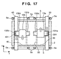
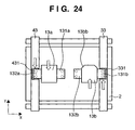
- Figs. 17 to 24 are schematic plan views of a wafer stage device according to the third embodiment of the present invention, and show the movement of the stages at different steps sequentially.
- the wafer stage device has movable elements 13a and 13b each formed to include a stage.
- C-chamfered portions 13bb serving as identifying units are formed on the movable element 13b to identify the combinations of two movable elements and two support bars.
- Anti-rotation members 131a and 132a are provided to the side surfaces of the movable element 13a, and anti-rotation members 131b and 132b are provided to the side surfaces of the movable element 13b.
- the anti-rotation members 131a, 132a, 131b, and 132b have holes (engaging portions).
- Support bars 33 and 43 are arranged such that they can be moved in the X direction by a driving mechanism (not shown) along guides 5.
- magnets can be provided to the support bars 33 and 43, and can drive them by the interaction with a stator 2.
- Slide members 331 and 431 are provided to the support bars 33 and 43, respectively, and can be moved in the Y direction by the driving mechanism (not shown) with respect to the support bars 33 and 43, respectively.
- two projections (regulating portions) 331a formed on the slide member 331 move vertically.
- two holes (engaging portions) 131aa of the anti-rotation member 131a and the projections (regulating portions) 331a engage with each other in a noncontact manner.
- the support bars and slide members are position-measured by interferometers and driven on the basis of the measurement results. Normally, when the movable element 13a moves in the X direction, the support bar 33 also moves in the X direction by a corresponding amount. When the movable element 13a moves in the Y direction, the slide member 331 also moves in the Y direction by a corresponding amount.
- the holes 131aa and projections 331a do not come into contact with each other.
- the inner surfaces of the holes 131aa can come into contact with the projections 331a to regulate the movement of the movable element.
- the projections 331a and 431a of the slide members 331 and 431 are regulated such that the support bars 33 and 43 are not rotated by the guides 5, the rotation, X-direction translation, and Y-direction translation of the movable elements can be regulated.
- an end 331b of the support bar 33 serves as a stopper.
- the stoppers are not limited to this structure, but, e.g., shock absorbers may be provided.
- shock absorbers 5a are preferably provided as the X-direction stoppers to the two ends in the X-direction stroke of each support bar, as shown in Fig. 17.
- Figs. 17 to 24 The movement of the wafer stage device, particularly the movable elements (stages) and support bars, will be described with reference to Figs. 17 to 24.
- the wafer (substrate) held on the movable element 13a including the stage by a vacuum chuck or the like has been exposed in an exposure process area 30, and the wafer on the movable element 13b including the stage has been alignment-adjusted in an alignment process area 40 in a parallel manner.
- the holes (engaging portions) of the anti-rotation member 131a engage with the projections (regulating portions) of the slide member 331 in a noncontact manner
- the holes (engaging portions) of the anti-rotation member 132b engage with the projections (regulating portions) of the slide member 431 in a noncontact manner.
- the projections (regulating portions) of the hatched slide members have moved to upper positions and engage with the holes of the anti-rotation members in a noncontact manner.
- the two movable elements 13a and 13b start swapping.
- the movable elements 13a and 13b start moving in directions of arrows. Interlocked with this, the slide members 331 and 431 also start moving.
- the movable element 13a moves in the +Y direction with the holes of the anti-rotation member 131a engaging with the projections of the slide member 331 in a noncontact manner.
- the slide member 331 also moves in the +Y direction.
- the movable element 13a ends moving in the +Y direction, it starts moving in the -X direction.
- the support bar 33 also starts moving in the -X direction (indicated by arrows in Fig. 18). Note that the slide member 331 stops.
- the movable element 13b moves in the -Y direction with the holes of the anti-rotation member 132b engaging with the projections of the slide member 431 in a noncontact manner.
- the slide member 431 also moves in the -Y direction.
- the movable element 13b ends moving in the -Y direction, it starts moving in the +X direction.
- the support bar 43 also starts moving in the +X direction (indicated by arrows in Fig. 18). Note that the slide member 431 stops.
- Fig. 19 shows a state wherein the movable elements 13a and 13b have moved to a swap process area 50.
- the movable elements 13a and 13b and the support bars 33 and 43 stop temporarily.
- the projections of the slide members 331 and 431 move downward to the lower positions, and their engagement with the anti-rotation members 131a and 132b in a noncontact manner is canceled.
- the slide members 331 and 431 move in the -Y and +Y directions, respectively.
- Fig. 19 shows a state wherein the movable elements 13a and 13b have moved to a swap process area 50.
- the movable elements 13a and 13b and the support bars 33 and 43 stop temporarily.
- the projections of the slide members 331 and 431 move downward to the lower positions, and their engagement with the anti-rotation members 131a and 132b in a noncontact manner is canceled.
- the slide members 331 and 431 move in the -Y and +Y directions, respectively.
- the projections of the slide members 331 and 431 move upward to the upper positions, and the holes of the anti-rotation member 132a engage with the projections of the slide member 431 in a noncontact manner and the holes of the anti-rotation member 131b engage with the projections of the slide member 331 in a noncontact manner.
- the movable elements 13a and 13b swap. After this, the movable element 13a is to move together with the support bar 43, and the movable element 13b is to move together with the support bar 33.
- the area where the position of the movable element can be regulated by the projections (regulating portions) formed on the slide member 331 which moves along the support bar 33 is the first area
- the area where the position of the movable element can be regulated by the projections (regulating portions) formed on the slide member 431 which moves along the support bar 43 is the second area.
- the position of the movable element located in the first area is regulated by the projections (regulating portions) formed on the slide member 331 which moves along the support bar 33 so that the movable element will not deviate from the target position.
- the position of the movable element located in the second area is regulated by the projections (regulating portions) formed on the slide member 431 which moves along the support bar 43 so that the movable element will not deviate from the target position.
- Fig. 23 shows a state wherein the movable element 13a has moved to the alignment process area 40 and the movable element 13b has moved to the exposure process area 30.
- the support bars 33 and 43 have also moved accordingly.
- the movable elements 13a and 13b and the slide members 331 and 431 move in directions of arrows as shown in Fig. 24, they are restored to the state of Fig. 17 (note that the two movable elements have swapped).
- one cycle is ended.
- the holes (engaging portions) of the anti-rotation members and the projections (regulating portions) of the slide members always engage with each other somewhere in a noncontact manner.
- the postures of the movable elements will not be largely changed at any time because the movable elements do not run uncontrollably to lead to an uncontrollable error.
- the slide members run by themselves on the support bars in the Y direction. If the cables for supplying power to the movable elements are attached to the movable elements through the slide members, the movable elements will not receive load change from the cables.
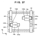
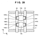
- Figs. 26 to 32 are schematic plan views of a wafer stage device according to the fourth embodiment of the present invention, and show the movement of the stages at different steps sequentially.
- the wafer stage device has movable elements 14a and 14b each formed to include a stage.
- C-chamfered portions 14bb serving as identifying units are formed on the movable element 14b to identify the combinations of two movable elements and two support bars.
- Anti-rotation members 141a and 142a are provided to the side surfaces of the movable element 14a, and anti-rotation members 141b and 142b are provided to the side surfaces of the movable element 14b.
- the anti-rotation members 141a, 142a, 141b, 142b have holes (engaging portions).
- Support bars 34 and 44 are arranged such that they can be moved in the X direction by a driving mechanism (not shown) along guides 5. In this driving mechanism, for example, slide members 341 and 342, and 441 and 442 are provided to the support bars 34 and 44, respectively, and can be moved by a driving mechanism (not shown) in the Y direction with respect to the support bars 33 and 44.
- the structure of the movable elements and support bars is identical to that of the third embodiment (Fig. 25).
- the holes (engaging portions) of the anti-rotation members and the projections (regulating portions) of the slide members engage with each other in a noncontact manner.
- the holes of the anti-rotation member can come into contact with the projections (regulating portions) of the slide member to regulate the movement of the movable element.
- the projections of the slide members 341 and 342, and 441 and 442 are regulated such that the support bars 34 and 44 are not rotated by the guides 5, the rotation, X-direction translation, and Y-direction translation of the movable elements can be regulated, but the slide members 341 and 342, and 441 and 442 can move freely in the Y direction with respect to the support bars 34 and 44.
- the ends of the support bars 34 and 44 serve as stoppers in the same manner as the support bar 33, as shown in Fig. 25.
- the stoppers are not limited to this structure, but, e.g., shock absorbers may be provided.
- shock absorbers 5a are preferably provided as the X-direction stoppers to the two ends in the X-direction stroke of each of the support bars 34 and 44, as shown in Fig. 26.
- Figs. 26 to 32 The movement of the wafer stage device, particularly the movable elements (stages) and support bars, will be described with reference to Figs. 26 to 32.
- the wafer held on the movable element 14a including the stage by a vacuum chuck or the like has been exposed in an exposure process area 30, and the wafer on the movable element 14b including the stage has been alignment-adjusted in an alignment process area 40 in a parallel manner.
- the holes (engaging portions) of the anti-rotation member 141a engage with the projections (regulating portions) of the slide member 341 in a noncontact manner
- the holes (engaging portions) of the anti-rotation member 142b engage with the projections (regulating portions) of the slide member 442 in a noncontact manner.
- the projections (regulating portions) of the hatched side members are at the upper positions and engage with the holes (engaging portions) of the anti-rotation members.
- the two movable elements start swapping.
- the movable elements 14a and 14b start moving in directions of arrows. Interlocked with this, the slide members 341 and 442 also start moving.
- the movable element 14a moves in the +Y direction with the holes of the anti-rotation member 141a engaging with the slide member 341 in a noncontact manner.
- the slide member 341 also moves in the +Y direction.
- the movable element 14a ends moving in the +Y direction, it starts moving in the -X direction.
- the support bar 34 also starts moving in the -X direction (arrows in Fig. 27). Note that the slide member 341 stops.
- the movable element 14b moves in the -Y direction with the holes of the anti-rotation member 142b engaging with the slide member 442 in a noncontact manner.
- the slide member 442 moves in the -Y direction.
- the movable element 14b ends moving in the -Y direction, it starts moving in the +X direction.
- the support bar 44 also starts moving in the +X direction (arrows in Fig. 27). Note that the slide member 442 stops.
- Fig. 28 shows a state wherein the movable elements 14a and 14b have moved to a swap process area 50.
- the slide member 342 has preferably been moved in advance to a position where it can engage with the anti-rotation member 141b in a noncontact manner.
- the slide member 441 has preferably been moved in advance to a position where it can engage with the anti-rotation member 142a in a noncontact manner.
- the movable elements 14a and 14b and the support bars 34 and 44 stop temporarily.
- the projections of the slide members 341 and 442 move downward to the lower positions, and the projections of the slide members 342 and 441 move upward to the upper positions.
- the movable elements 14a and 14b swap. After this, the movable element 14a is to move together with the support bar 44, and the movable element 14b is to move together with the support bar 34.
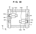
- the area where the position of the movable element can be regulated by the projections (regulating portions) formed on the slide members 341 and 342 which move along the support bar 34 is the first area
- the area where the position of the movable element can be regulated by the projections (regulating portions) formed on the slide members 441 and 442 which move along the support bar 44 is the second area.
- the position of the movable element located in the first area is regulated by the projections (regulating portions) formed on the slide members 341 and 342 which move along the support bar 34 so that the movable element will not deviate from the target position.
- the position of the movable element located in the second area is regulated by the projections (regulating portions) formed on the slide members 441 and 442 which move along the support bar 44 so that the movable element will not deviate from the target position.
- Fig. 30 shows a state wherein the movable element 14a has moved to the alignment process area 40 and the movable element 14b has moved to the exposure process area 30.
- the support bars 34 and 44 have also moved accordingly.
- the movable elements 14a and 14b and side members 342 and 441 move in directions of arrows as shown in Fig. 31, they are restored to the state of Fig. 26 (note that the movable elements have swapped).
- one support bar is provided with two slide members, when the two, right and left movable elements are to swap as in the third embodiment (see Fig. 21), the slide members need not move. Therefore, the throughput is increased.
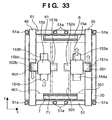
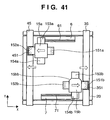
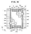
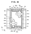
- Figs. 33 to 42 are schematic plan views of a wafer stage device according to the fifth embodiment of the present invention, and show the movement of the stages at different steps sequentially.
- the wafer stage device has a stator 20 and two movable elements 15a and 15b.
- the stator 20 and movable element 15a form one plane motor
- the stator 20 and movable element 15b form the other plane motor.
- C-chamfered portions 15bb serving as identifying units are formed on the movable element 15b to identify the combinations of two movable elements and two support bars.
- Anti-rotation members 151a, 152a, 153a, and 154a are provided to the side surfaces of the movable element 15a, and anti-rotation members 151b, 152b, 153b, and 154b are provided to the side surfaces of the movable element 15b.
- each of the anti-rotation members 151a, 152a, 151b, and 152b has two holes (engaging portions) in the same manner as the anti-rotation member 131a of Fig. 25, and the anti-rotation members 153a, 154a, 153b, and 154b have recesses (engaging portions) in the same manner as the anti-rotation member 121a of Fig. 16.
- Support bars 35 and 45 are arranged such that they can be moved in the X direction by a driving mechanism (not shown) along guides 51.
- this driving mechanism for example, magnets can be provided to the support bars 35 and 45, and can drive them by the interaction with the stator 20.
- Slide members 351 and 451 each having two projections (regulating portions), like the projections 331a (regulating portions) of Fig. 25, are provided to the support bars 35 and 45, respectively, and can be moved in the Y direction by the driving mechanism (not shown) with respect to the support bars.
- Fixed bars 6 and 7 respectively have ridges 61 and 71 which move vertically with respect to the fixed bars 6 and 7.
- the projections (regulating portions) formed on the slide members 351 and 451 move vertically.
- the holes (engaging portions) of the anti-rotation members 151a and 152a, and 151b and 152b and the projections (regulating portions) of the corresponding slide members 351 and 451 engage with each other in a noncontact manner.
- the ridges (regulating portions) 61 and 71 formed on the fixed bars 6 and 7 move vertically.
- the recesses (engaging portions) of the anti-rotation members 153a and 154a, and 153b and 154b and the ridges (regulating portions) 61 and 71 of the corresponding fixed bars 6 and 7 engage with each other in a noncontact manner.
- the projections of the slide members 351 and 451 are regulated such that the support bars 35 and 45 are not rotated by the guides 51.
- the rotation, X-direction translation, and Y-direction translation of the movable elements 15a and 15b can be regulated.
- the ends of the support bars 35 and 45 serve as stoppers, in the same manner as in the support bar 33 shown in Fig. 25.
- the stoppers are not limited to this structure, but, e.g., shock absorbers may be provided.
- shock absorbers 51a are provided as the X-direction stoppers to the two ends in the X-direction stroke of each support bar as shown in Fig. 33.
- the ends of the fixed bars are preferably formed each like the end 322a shown in Fig. 16, so that they can serve as stoppers.
- the stoppers are not limited to this structure, but, e.g., shock absorbers may be provided.
- stoppers or bearings are preferably provided to the two sides of each of the anti-rotation members 153a, 154a, 153b, and 154b, so that the recesses of the anti-rotation members and the ridges of the fixed bars will not collide against or be dragged by each other.
- Figs. 33 to 42 The movement of the wafer stage device, particularly the movable elements (stages), support bars, and fixed bars will be described with reference to Figs. 33 to 42.
- the wafer (substrate) held on the movable element 15a including the stage by a vacuum chuck or the like has been exposed in an exposure process area 301, and the wafer on the movable element 15b including the stage has been alignment-adjusted in an alignment process area 401 in a parallel manner.
- the holes (engaging portions) of the anti-rotation member 151a engage with the projections (regulating portions) of the slide member 351 in a noncontact manner
- the holes (engaging portions) of the anti-rotation member 152b engage with the projections (regulating portions) of the slide member 451 in a noncontact manner.
- the projections of the hatched slide members have moved to the upper positions and engage with the holes of the anti-rotation members in a noncontact manner.
- the two, left and right movable elements start swapping.
- the movable elements 15a and 15b start moving in directions of arrows. Interlocked with this, the slide members 351 and 451 also start moving.
- the movable element 15a moves in the +Y direction with the holes of the anti-rotation member 151a engaging with the projections of the slide member 351 in a noncontact manner.
- the slide member 351 also moves in the +Y direction.
- the movable element 15a ends moving in the +Y direction, it starts moving in the -X direction.
- the support bar 35 also starts moving in the -X direction (indicated by arrows in Fig. 34). Note that the slide member 351 stops. At this time, the ridge 61 of the fixed bar 6 is at the lower position.
- the slide member 451 also moves in the -Y direction.
- the movable element 15b ends moving in the -Y direction, it starts moving in the +X direction.
- the support bar 45 also starts moving in the +X direction (indicated by arrows in Fig. 34). Note that the slide member 451 stops. At this time, the ridge 71 of the fixed bar 7 is at the lower position. When the ridge 71 of the fixed bar 7 moves upward to the upper position, it can engage with the anti-rotation member 154b in a noncontact manner.
- the ridges 61 and 71 of the fixed bars 6 and 7 move upward, and respectively engage with the anti-rotation members 153a and 154b in a noncontact manner (the ridges of the fixed bars that have moved upward are hatched).
- the slide members 351 and 451 respectively engage with the anti-rotation members 151a and 152b.
- the movable elements 15a and 15b enter a swap process area 501 and continuously move in the X direction, but the support bars 35 and 45 stop at predetermined positions.
- the slide members 351 and 451 move in directions of arrows to swap the movable elements 15a and 15b.
- the support bars 35 and 45 start moving in directions of arrows (indicated as short arrows).
- the support bars 35 and 45 and the movable element 15b and 15a move in an interlocked manner.
- the projections of the slide members 351 and 451 move upward to the upper positions and respectively engage with the anti-rotation members 151b and 152a in a noncontact manner.
- the movable elements 15a and 15b swap.
- the movable element 15a is to move together with the support bar 45
- the movable element 15b is to move together with the support bar 35.
- the area where the position of the movable element can be regulated by the projections (regulating portions) formed on the slide member 351 which moves along the support bar 35 and the ridge (regulating portion) 61 formed on the fixed bar 6 is the first area
- the area where the position of the movable element can be regulated by the projections (regulating portions) formed on the slide member 451 which moves along the support bar 45 and the ridge (regulating portion) 71 formed on the fixed bar 7 is the second area.
- the position of the movable element located in the first area is regulated by the projections (regulating portions) formed on the slide member 351 which moves along the support bar 35 and the ridge (regulating portion) 61 formed on the fixed bar 6 so that the movable element will not deviate from the target position.
- the position of the movable element located in the second area is regulated by the projections (regulating portions) formed on the slide member 451 which moves along the support bar 45 and the ridge (regulating portion) 71 formed on the fixed bar 7 so that the movable element will not deviate from the target position.
- Fig. 41 shows a state wherein the movable element 15a has moved to the alignment process area 401 and the movable element 15b has moved to the exposure process area 301.
- the fixed bar ridges 61 and 71 have moved downward to the lower positions, so that the movable elements 15a and 15b can move in the -Y and +Y directions, respectively.
- the support bars 35 and 45 have also moved accordingly.
- one cycle is ended.
- the holes or recesses (engaging portions) of the anti-rotation members of the movable elements and the projections or ridges (regulating portions) of the slide members or support bars always engage with each other somewhere in a noncontact manner.
- the projections of the slide members and the ridges of the fixed bars move upward to the upper position to engage with the holes or recesses of the anti-rotation members.
- the postures of the movable elements will not be largely changed at any time because the movable elements run uncontrollably to lead to an uncontrollable error.
- the support bars 35 and 45 are respectively provided with the slide members 351 and 451 which can move in the Y direction, and the fixed bars 6 and 7 are respectively provided with the ridges 61 and 71 which move only vertically.
- the ridges of the fixed bars may be of a type that can slide in the X direction, and the ridges of the support bars may be of a type that move only vertically.
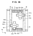
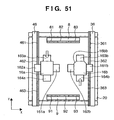
- Figs. 43 to 51 are schematic plan views of a wafer stage device according to the sixth embodiment of the present invention, and show the movement of the stages at different steps sequentially.
- the wafer stage device has a stator 20 and two movable elements 16a and 16b.
- the stator 20 and movable element 16a form one plane motor
- the stator 20 and movable element 16b form the other plane motor.
- C-chamfered portions 16bb serving as identifiers are formed on the movable element 16b to identify the combinations of two movable elements and two support bars or fixed bars.
- Anti-rotation members 161a, 162a, 163a, and 164a are provided to the side surfaces of the movable element 16a, and anti-rotation members 161b, 162b, 163b, and 164b are provided to the side surfaces of the movable element 16b. All the anti-rotation members have recesses (engaging portions) in the same manner as the anti-rotation member 121a of Fig. 16.
- Support bars 36 and 46 are arranged such that they can be moved in the X direction by a driving mechanism (not shown) along guides 51.
- a driving mechanism for example, magnets can be provided to the support bars 36 and 46 to drive the support bars 36 and 46 by the interaction with the stator 20.
- Ridges (regulating portions) 361, 362, and 363, and 461, 462, and 463 are provided to the support bars 36 and 46, respectively.
- the ridges 361, 363, 461, and 463 can vertically move independently of each other with respect to the support bars.
- the ridges 362 and 462 are fixed at the upper positions.
- the wafer stage device is further provided with fixed bars 8 and 9.
- the fixed bars 8 and 9 are respectively provided with ridges (regulating portions) 81, 82, and 83, and 91, 92, and 93.
- the ridges 81, 83, 91, and 93 can vertically move independently of each other with respect to the fixed bars.
- the ridges 82 and 92 are fixed at the upper positions.
- the structure of the recesses of the anti-rotation members of the movable elements and the ridges of the support bars or fixed bars is identical to that shown in Fig. 16. Normally, the recesses of the anti-rotation members and the ridges of the support bars engage with each other in a noncontact manner. When the movable element runs uncontrollably due to some abnormalities, the recess of the anti-rotation member can come into contact with the support bar ridge to regulate the movement of the movable element.
- each support bar preferably has a shape like that of the end 322a of Fig. 16, so that the support bars can serve as stoppers.
- the stoppers are not limited to this structure, but, e.g., shock absorbers may be provided.
- each fixed bar preferably has a shape like that of the end 322a of Fig. 16, so that the fixed bars can serve as stoppers.
- shock absorbers 51a are preferably provided as the X-direction stoppers to the two ends in the X-direction stroke of each support bar, as shown in Fig. 43.
- each of the anti-rotation members 161a, 162a, 163a, 164a, 161b, 162b, 163b, and 164b is preferably provided with stoppers or bearings at its two sides, so that the recess of the anti-rotation member and the support bar ridge or fixed bar ridge will not collide against or be dragged by each other.
- Figs. 43 to 51 The movement of the wafer stage device, particularly the movable elements (stages), support bars, and fixed bars will be described with reference to Figs. 43 to 51.
- the wafer held on the movable element 16a including the stage by a vacuum chuck or the like has been exposed in an exposure process area 301, and the wafer on the movable element 16b including the stage has been alignment-adjusted in an alignment process area 401 in a parallel manner.
- the recess (engaging portion) of the anti-rotation member 161a engages with the support bar ridge (regulating portions) 362 in a noncontact manner
- the recess (engaging portion) of the anti-rotation member 162b engages with the support bar ridge (regulating portion) 462 in a noncontact manner.
- the hatched ridges (regulating portions) have moved upward to the upper positions.
- the two movable elements start swapping.
- the movable elements 16a and 16b start moving in directions of arrows.
- the movable element 16a moves in the +Y direction with the recess of the anti-rotation member 161a engaging with the ridges 362 and 361 of the support bar 36 in a noncontact manner.
- the movable element 16a ends moving in the +Y direction, it starts moving in the -X direction.
- the support bar 36 also starts moving in the -X direction (arrows in Fig. 44).
- the ridge 83 of the fixed bar 8 has moved downward to the lower position.
- the ridge 83 of the fixed bar 8 moves upward to the upper position, it can engage with the anti-rotation member 163a in a noncontact manner.
- the movable element 16b moves in the -Y direction with the recess of the anti-rotation member 162b engaging with the ridges 462 and 463 of the support bar 46 in a noncontact manner.
- the movable element 16b ends moving in the -Y direction, it starts moving in the +X direction.
- the support bar 46 also starts moving in the +X direction (arrows in Fig. 44).
- the ridge 91 of the fixed bar 9 has moved downward to the lower position.
- the ridge 91 of the fixed bar 9 moves upward to the upper position, it can engage with the anti-rotation member 164b in a noncontact manner.
- the ridges 83 and 91 of the fixed bars 8 and 9 move upward to the upper positions, and respectively engage with the anti-rotation members 163a and 164b in a noncontact manner.
- the ridges 361 and 463 of the support bars 36 and 46 also respectively engage with the anti-rotation members 161a and 162b in a noncontact manner.
- the ridges 361 and 463 of the supports bar 36 and 46 respectively move downward to the lower positions.
- the support bars 36 and 46 that engage with the movable elements 16a and 16b in a noncontact manner are disengaged from them and are decelerated (deceleration is indicated by short arrows).
- the movable elements 16a and 16b enter a swap process area 501 and continuously move in the X direction, but the support bars 36 and 46 stop at predetermined positions (at this time, the ridges 361 and 463 of the support bars 36 and 46 have returned to the upper positions).
- the support bars 36 and 46 start moving in directions of arrows (indicated by short arrows). At this time, the support bar ridges 363 and 461 have moved downward to the lower positions.
- the support bars 36 and 46 and the movable element 16a and 15b move in an interlocked manner.
- the support bar ridges 363 and 463 move upward to the upper positions and respectively engage with the anti-rotation members 161b and 162a in a noncontact manner.
- the movable elements 16a and 16b swap.
- the movable element 16a is to move together with the support bar 46
- the movable element 16b is to move together with the support bar 36.
- the area where the position of the movable element can be regulated by the ridges (regulating portions) 361, 362, and 363 formed on the support bar 36 and the ridges 81, 82, and 83 formed on the fixed bar 8 is the first area
- the area where the position of the movable element can be regulated by the ridges (regulating portions) 461, 462, and 463 formed on the support bar 46 and the ridges (regulating portions) 91, 92, and 93 formed on the fixed bar 9 is the second area.
- the position of the movable element located in the first area is regulated by the ridges (regulating portions) 361, 362, and 363 formed on the support bar 36 and the ridges 81, 82, and 83 formed on the fixed bar 8 so that the movable element will not deviate from the target position.
- the position of the movable element located in the second area is regulated by the ridges (regulating portions) 461, 462, and 463 formed on the support bar 46 and the ridges (regulating portions) 91, 92, and 93 formed on the fixed bar 9 so that the movable element will not deviate from the target position.
- Fig. 50 shows a state wherein the movable element 16a has moved to the alignment process area 401 and the movable element 16b has moved to the exposure process area 301.
- the ridges 81 and 93 of the fixed bars 8 and 9 have moved downward to the lower positions, so that the movable elements 16a and 16b can move in the -Y and +Y directions, respectively.
- the support bars 36 and 46 have also moved accordingly.
- the movable elements 16a and 16b move in directions of arrows as shown in Fig. 51, they are restored to the state of Fig. 33 (note that the movable elements have swapped).
- one cycle is ended.
- the recesses (engaging portions) of the anti-rotation members of the movable elements and the ridges (regulating portions) of the support bars or fixed bars always engage with each other somewhere in a noncontact manner.
- the ridges of the support bars and the ridges of the fixed bars move upward to the upper positions to engage with the recesses of the anti-rotation members.
- the postures of the movable elements will not be largely changed at any time because the movable elements do not run uncontrollably to lead to an uncontrollable error.
- the engaging portions and regulating portions move vertically in the first to sixth embodiments, they are not limited to this type, but can move, e.g., to the left and right.
- the recesses are formed in the movable elements and the ridges are formed on the bars.
- ridges may be formed on the movable elements and recesses may be formed in the bars.
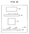
- Fig. 53 is a view showing the schematic structure of an exposure apparatus to which a twin-stage wafer stage device represented by the above embodiments is applied.
- the exposure apparatus shown in Fig. 53 has a wafer stage device 200 represented by the above embodiments.
- the wafer stage device 200 has two stages (movable elements) ST1 and ST2 on a stator SM which has a planer portion.
- the stages ST1 and ST2 can be driven on the planer portion.
- the area where the stages ST1 and ST2 can move on the planer portion includes an exposure process area, an alignment process area, and a swap process area between the exposure process area and alignment process area. When one stage is used for exposure in the exposure process area, the other stage can be used for alignment in the alignment process area.
- the two stages ST1 and ST2 can swap in the swap process area.
- the positions of the two stages ST1 and ST2 are regulated by a regulating mechanism which can include the engaging portions and regulating portions as described above, so that the stages ST1 and ST2 will not deviate from target positions.
- the engaging portions and regulating portions do not engage with each other.
- the engaging portions and regulating portions come into contact with each other in an abnormal state wherein the stages ST1 and ST2 are to deviate from the target positions, to prevent deviation of the stages ST1 and ST2.
- the pattern of a reticle (original) R held by a reticle stage RS is projected onto a wafer (substrate), which is held by a stage located within the exposure process area and coated with a photo sensitive agent, through an projection optical system OP, and a latent image pattern corresponding to the pattern of the reticle R is formed on the photo sensitive agent.
- the reticle R is illuminated by an illumination optical system 100.
- a scheme can be employed with which a latent image is formed on the photo sensitive agent while scanning the wafer with a charged-particle beam such as an electron beam.
- Fig. 54 is a flowchart showing the flow of the entire semiconductor device manufacturing process.
- step 1 circuit design
- step 2 mask fabrication
- step 3 wafer manufacture
- step 4 wafer process
- step 5 wafer process
- step 5 semiconductor chip is formed from the wafer fabricated in step 4.
- This step includes processes such as assembly (dicing and bonding) and packaging (chip encapsulation).
- inspections including operation check test and durability test of the semiconductor device fabricated in step 5 are performed.
- a semiconductor device is finished with these steps and shipped (step 7).
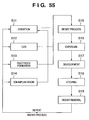
- Fig. 55 is a flowchart showing the detailed flow of the wafer process.
- step 11 oxidation
- step 12 CVD
- step 13 electrode formation
- step 14 ion implantation
- ions are implanted in the wafer.
- step 15 resist process
- step 16 exposure
- step 18 etching
- steps other than the developed resist image are removed.
- step 19 resist removal
Landscapes
- Physics & Mathematics (AREA)
- General Physics & Mathematics (AREA)
- Exposure And Positioning Against Photoresist Photosensitive Materials (AREA)
- Exposure Of Semiconductors, Excluding Electron Or Ion Beam Exposure (AREA)
- Linear Motors (AREA)
- Container, Conveyance, Adherence, Positioning, Of Wafer (AREA)
Abstract
Description
Claims (27)
- An alignment apparatus comprising:a stator which has a planer portion including first and second areas;first and second movable elements which move on the planer portion; anda regulating mechanism which regulates positions of the first and second movable elements, whereinthe first and second movable elements are driven to target positions by a force that acts among the first and second movable elements and stator, andthe regulating mechanism includesa first regulator which regulates the position of, of the first and second movable elements, one which is located in the first area such that the movable element will not deviate from the target position, anda second regulator which regulates the position of, of the first and second movable elements, one which is located in the second area such that the movable element will not deviate from the target position.
- The apparatus according to claim 1, wherein the first and second areas partially overlap.
- The apparatus according to claim 1, wherein the first and second regulators do not come into contact with the first and second movable elements while the first and second movable elements are located at the target positions.
- The apparatus according to claim 1, wherein the first and second movable elements respectively include engaging portions, and deviation of the movable elements from the target positions is regulated by contact of the first or second regulators and the engaging portions.
- The apparatus according to claim 4, wherein the regulating mechanism includes a driving mechanism which moves the engaging portions and/or the first and second regulators when the first and second movable elements are to be swapped between the first and second areas.
- The apparatus according to claim 1, wherein the first and second movable elements respectively include at least first and second engaging portions, the position of the movable element which has been driven from the second area to the first area is regulated by the first engaging portion and first regulator, and the position of the movable element which has been driven from the first area to the second area is regulated by the second engaging portion and second regulator.
- The apparatus according to claim 4, wherein the engaging portions include recesses, ridges, or holes.
- The apparatus according to claim 1, wherein the first regulator is provided to a first support moving member which moves together with, of the first and second movable elements, one which is located in the first area, and the second regulator is provided to a second support moving member which moves together with, of the first and second movable elements, one which is located in the second area.
- The apparatus according to claim 8, wherein the first and second support moving members can move in such directions that a distance between the first and second support moving members changes.
- The apparatus according to claim 9, wherein the first and second regulators extend along longitudinal directions of the first and second support moving members, respectively, and the first and second support moving members stop when the first and second movable elements move along the longitudinal directions, and move in the longitudinal directions, when the first and second movable elements move along directions perpendicular to the longitudinal directions, together with the first and second movable elements.
- The apparatus according to claim 9, wherein the first regulator can move in the longitudinal direction of the first support moving member together with the movable element located in the first area, and the second regulator can move along the longitudinal direction of the second support moving member together with the movable element located in the second area.
- The apparatus according to claim 8, wherein the first and second support moving members have stoppers which regulate moving ranges of the first and second movable elements in the longitudinal directions.
- The apparatus according to claim 8, further comprising a second stopper which regulates moving ranges of the first and second support moving members.
- The apparatus according to claim 1, further comprising:wherein the first regulator is provided to the first support moving member and first fixed member to regulate the position of the movable element in the first area, and the second regulator is provided to the second support moving member and second fixed member to regulate the position of the movable element in the second area.a first support moving member which is arranged to extend along a second direction perpendicular to a first direction and moves along the first direction together with, of the first and second movable elements, one which is located in the first area;a second support moving member which is arranged to extend along the second direction and moves together with, of the first and second movable elements, one which is located in the second area;a first fixed member which is arranged within the first area so as to extend along the first direction between the first and second support moving members; anda second fixed member which is arranged within the second area so as to extend along the first direction between the first and second support moving members,
- The apparatus according to claim 4, wherein a portion through which the first and second regulators and the engaging portions can be in contact with each other is formed such that when the engaging portions come into contact with the first and second regulators, the engaging portions slide on the first and second regulators.
- The apparatus according to claim 4, wherein the first and second regulators and the engaging portions come into contact with each other through rollers.
- The apparatus according to claim 1, wherein each of the first and second regulators is divided into a plurality of pieces, the plurality of divisional pieces being driven independently of each other.
- The apparatus according to claim 1, wherein the first and second regulators and the first and second movable elements are formed such that even when a power supply is turned off, the positions of the first and second movable elements are regulated by the first and second regulators.
- The apparatus according to claim 1, wherein at least one of the first and second movable elements has an identifying unit for identifying the remaining one of the first and second movable elements.
- The apparatus according to claim 1, further comprising a sensor which checks that the positions of the first and second movable elements are regulated by the first and second regulators.
- The apparatus according to claim 1, wherein
in a first step, the first and second movable elements arranged on a line along a first direction are moved in opposite directions along a second direction perpendicular to the first direction,
subsequently, in a second step, the first and second movable elements are moved in opposite directions along the first direction, and
subsequently, in a third step, the first and second movable elements are moved in the opposite directions along the second direction so that the first and second movable elements are arranged on the line again,
thereby swapping the first and second movable elements. - The apparatus according to claim 21, further comprising first and second support moving members which extend in the second direction and oppose each other, the first and second regulators being provided to the first and second support moving members, respectively, wherein
in the first step, while the first and second support moving members are set still, the first and second movable elements are moved along the second direction while regulating the positions of the first and second movable elements by the first and second regulators,
in the second step, the first and second support moving members are moved along the first direction and the first and second movable elements are moved along the second direction while regulating the positions of the first and second movable elements by the first and second regulators, and
in the third step, while the first and second support moving members are set still, the first and second movable elements are moved along the second direction while regulating the positions of the first and second movable elements by the first and second regulators. - The apparatus according to claim 22, wherein in the second step, the first and second movable elements are moved along the first direction to positions where the first and second movable elements are arranged on a line along the second direction, and when the second step is to shift to the third step, the first and second regulators that are to regulate the positions of the first and second movable elements are swapped.
- The apparatus according to claim 21, further comprising:first and second support moving members which extend in the second direction and oppose each other; andfirst and second fixed members arranged between the first and second support moving members along the first direction, whereinthe first regulator is provided to the first support moving member and first fixed member,the second regulator is provided to the second support moving member and second fixed member,in the first step, while the first and second support moving members are set still, the first and second movable elements are moved along the second direction while regulating the positions of the first and second movable elements by the first and second regulators provided to the first and second support moving members,in the second step, the first and second support moving members are moved along the first direction, the first and second movable elements are moved along the first direction while regulating the positions of the first and second movable elements by the first and second regulators provided to the first and second support moving members, thereafter the first and second moving members are set still, and the first and second movable elements are moved along the first direction while regulating the positions of the first and second movable elements by the first and second regulators provided to the first and second fixed members, andin the third step, while the first and second support moving members are set still, the first and second movable elements are moved along the second direction while regulating the positions of the first and second movable elements by the first and second regulators provided to the first and second support moving members.
- An exposure apparatus for forming a latent image of a pattern on a photo sensitive agent on a substrate to which the photo sensitive agent has been applied, comprising:an alignment apparatus which has first and second stages and holds and aligns substrates on the first and second stages; anda pattern forming unit which forms a latent image pattern on the photo sensitive agent on the substrate held on, of the first and second stages, one which is located within an exposure process area,the exposure apparatus comprising, as the alignment apparatus, an alignment apparatus according to claim 1, and the first and second movable elements including the first and second stages, respectively.
- A device manufacturing method comprising:a step of forming, by using an exposure apparatus according to claim 25, a latent image on a photo sensitive agent on a substrate to which the photo sensitive agent has been applied,a step of developing the latent image pattern, anda step of using at least a part of the substrate to make a device.
- Stage apparatus, for use with exposure apparatus for exposing a substrate with a pattern of radiation, comprising:a plurality of stages movable over a common stage support surface; andfirst and second stage restraining means, each for interacting with a stage at a respective region of the stage support surface so as to restrain excessive or unwanted movement of the stage,the first and second stage restraining means each being arranged to release a stage with which it is interacting, so as to allow the stage to move out of the respective region, and to begin to interact with another stage which moves into the respective region.
Applications Claiming Priority (2)
| Application Number | Priority Date | Filing Date | Title |
|---|---|---|---|
| JP2004106245 | 2004-03-31 | ||
| JP2004106245A JP2005294468A (en) | 2004-03-31 | 2004-03-31 | Positioning apparatus, exposure apparatus, and device manufacturing method |
Publications (2)
| Publication Number | Publication Date |
|---|---|
| EP1582932A2 true EP1582932A2 (en) | 2005-10-05 |
| EP1582932A3 EP1582932A3 (en) | 2010-01-20 |
Family
ID=34880085
Family Applications (1)
| Application Number | Title | Priority Date | Filing Date |
|---|---|---|---|
| EP05251985A Withdrawn EP1582932A3 (en) | 2004-03-31 | 2005-03-30 | Alignment apparatus, exposure apparatus, and device manufacturing method |
Country Status (3)
| Country | Link |
|---|---|
| US (1) | US20050218335A1 (en) |
| EP (1) | EP1582932A3 (en) |
| JP (1) | JP2005294468A (en) |
Cited By (8)
| Publication number | Priority date | Publication date | Assignee | Title |
|---|---|---|---|---|
| WO2010111973A1 (en) * | 2009-04-03 | 2010-10-07 | 清华大学 | Dual-stage exchange system for lithographic apparatus |
| WO2010111969A1 (en) * | 2009-04-03 | 2010-10-07 | 清华大学 | Dual-stage exchange system for lithographic apparatus |
| ITUD20090129A1 (en) * | 2009-07-03 | 2011-01-04 | Applied Materials Inc | SUBSTRATE PROCESSING SYSTEM |
| CN101551599B (en) * | 2009-04-03 | 2011-07-20 | 清华大学 | Double-stage switching system of photoetching machine wafer stage |
| CN102317865A (en) * | 2009-02-13 | 2012-01-11 | 麦克罗尼克迈达塔有限责任公司 | Multi-table lithographic systems |
| CN102495530A (en) * | 2011-11-12 | 2012-06-13 | 哈尔滨工业大学 | Cross-beam-type step-scanning and three-step double-stage exchanging apparatus and method |
| US8361371B2 (en) | 2008-02-08 | 2013-01-29 | Molecular Imprints, Inc. | Extrusion reduction in imprint lithography |
| EP2064596B1 (en) * | 2006-09-22 | 2017-09-06 | Shanghai Micro Electronics Equipment (Group) Co., Ltd. | Dual stage positioning and switching system |
Families Citing this family (5)
| Publication number | Priority date | Publication date | Assignee | Title |
|---|---|---|---|---|
| JP4677267B2 (en) * | 2005-04-04 | 2011-04-27 | キヤノン株式会社 | Planar stage apparatus and exposure apparatus |
| JP2008078499A (en) * | 2006-09-22 | 2008-04-03 | Canon Inc | Support apparatus, exposure apparatus, and device manufacturing method |
| KR100914494B1 (en) | 2007-01-22 | 2009-08-28 | 정훈택 | Mover |
| NL2010628A (en) | 2012-04-27 | 2013-10-29 | Asml Netherlands Bv | Lithographic apparatus comprising an actuator, and method for protecting such actuator. |
| CN108988597B (en) * | 2018-08-10 | 2019-12-10 | 深圳大学 | Embedded linear switch reluctance motor device |
Family Cites Families (16)
| Publication number | Priority date | Publication date | Assignee | Title |
|---|---|---|---|---|
| JP3548353B2 (en) * | 1996-10-15 | 2004-07-28 | キヤノン株式会社 | Stage apparatus, exposure apparatus and device manufacturing method using the same |
| JP3745167B2 (en) * | 1998-07-29 | 2006-02-15 | キヤノン株式会社 | Stage apparatus, exposure apparatus, device manufacturing method, and stage driving method |
| JP2001118773A (en) * | 1999-10-18 | 2001-04-27 | Nikon Corp | Stage device and exposure device |
| JP2001160530A (en) * | 1999-12-01 | 2001-06-12 | Nikon Corp | Stage device and exposure device |
| EP1111471B1 (en) * | 1999-12-21 | 2005-11-23 | ASML Netherlands B.V. | Lithographic projection apparatus with collision preventing device |
| US6836093B1 (en) * | 1999-12-21 | 2004-12-28 | Nikon Corporation | Exposure method and apparatus |
| TWI223734B (en) * | 1999-12-21 | 2004-11-11 | Asml Netherlands Bv | Crash prevention in positioning apparatus for use in lithographic projection apparatus |
| JP2002280283A (en) * | 2001-03-16 | 2002-09-27 | Canon Inc | Substrate processing equipment |
| EP1300932B1 (en) * | 2001-10-05 | 2013-12-18 | Canon Kabushiki Kaisha | Linear motor, stage apparatus, and exposure apparatus |
| US6815699B2 (en) * | 2001-12-11 | 2004-11-09 | Asml Netherlands B.V. | Lithographic apparatus and device manufacturing method |
| US6927505B2 (en) * | 2001-12-19 | 2005-08-09 | Nikon Corporation | Following stage planar motor |
| JP4227452B2 (en) * | 2002-12-27 | 2009-02-18 | キヤノン株式会社 | Positioning device and exposure apparatus using the positioning device |
| JP2005142501A (en) * | 2003-11-10 | 2005-06-02 | Canon Inc | Stage apparatus, exposure apparatus, and device manufacturing method |
| JP4307288B2 (en) * | 2004-02-25 | 2009-08-05 | キヤノン株式会社 | Positioning device |
| JP2005253179A (en) * | 2004-03-03 | 2005-09-15 | Canon Inc | Positioning apparatus, exposure apparatus, and device manufacturing method |
| JP2005303196A (en) * | 2004-04-15 | 2005-10-27 | Canon Inc | Positioning apparatus, exposure apparatus, and semiconductor device manufacturing method |
-
2004
- 2004-03-31 JP JP2004106245A patent/JP2005294468A/en not_active Withdrawn
-
2005
- 2005-03-29 US US11/091,673 patent/US20050218335A1/en not_active Abandoned
- 2005-03-30 EP EP05251985A patent/EP1582932A3/en not_active Withdrawn
Cited By (13)
| Publication number | Priority date | Publication date | Assignee | Title |
|---|---|---|---|---|
| EP2064596B1 (en) * | 2006-09-22 | 2017-09-06 | Shanghai Micro Electronics Equipment (Group) Co., Ltd. | Dual stage positioning and switching system |
| US8361371B2 (en) | 2008-02-08 | 2013-01-29 | Molecular Imprints, Inc. | Extrusion reduction in imprint lithography |
| CN102317865A (en) * | 2009-02-13 | 2012-01-11 | 麦克罗尼克迈达塔有限责任公司 | Multi-table lithographic systems |
| CN102317865B (en) * | 2009-02-13 | 2014-03-12 | 麦克罗尼克迈达塔有限责任公司 | Multi-table lithographic systems |
| US8836918B2 (en) | 2009-04-03 | 2014-09-16 | Tsinghua University | Dual-stage exchange system for lithographic apparatus |
| WO2010111969A1 (en) * | 2009-04-03 | 2010-10-07 | 清华大学 | Dual-stage exchange system for lithographic apparatus |
| WO2010111973A1 (en) * | 2009-04-03 | 2010-10-07 | 清华大学 | Dual-stage exchange system for lithographic apparatus |
| CN101551599B (en) * | 2009-04-03 | 2011-07-20 | 清华大学 | Double-stage switching system of photoetching machine wafer stage |
| US8860927B2 (en) | 2009-04-03 | 2014-10-14 | Tsinghua University | Dual-stage exchange system for lithographic apparatus |
| WO2011000442A1 (en) * | 2009-07-03 | 2011-01-06 | Applied Materials, Inc. | Substrate processing system |
| CN102473588B (en) * | 2009-07-03 | 2015-06-03 | 应用材料公司 | Substrate processing system |
| ITUD20090129A1 (en) * | 2009-07-03 | 2011-01-04 | Applied Materials Inc | SUBSTRATE PROCESSING SYSTEM |
| CN102495530A (en) * | 2011-11-12 | 2012-06-13 | 哈尔滨工业大学 | Cross-beam-type step-scanning and three-step double-stage exchanging apparatus and method |
Also Published As
| Publication number | Publication date |
|---|---|
| JP2005294468A (en) | 2005-10-20 |
| EP1582932A3 (en) | 2010-01-20 |
| US20050218335A1 (en) | 2005-10-06 |
Similar Documents
| Publication | Publication Date | Title |
|---|---|---|
| KR101539191B1 (en) | Exposure method, exposure apparatus, and device manufacturing method | |
| US8009275B2 (en) | Movable stage apparatus | |
| KR102203305B1 (en) | Exposure device and exposure method, and device-manufacturing method | |
| KR101729791B1 (en) | Exposure apparatus, exposure method, and device manufacturing method | |
| EP1582932A2 (en) | Alignment apparatus, exposure apparatus, and device manufacturing method | |
| US7289194B2 (en) | Positioning apparatus, exposure apparatus, and device manufacturing method | |
| KR100895640B1 (en) | Stage apparatus, exposure apparatus, and method for manufacturing device | |
| US7817251B2 (en) | Supporting apparatus, exposure apparatus, and device manufacturing method | |
| KR20210059029A (en) | Mobile body apparatus, exposure apparatus, production method for flat panel display, production method for device, and drive method for mobile body | |
| US20190049856A1 (en) | Exposure apparatus, exposure method, manufacturing method of flat-panel display, and device manufacturing method | |
| WO2014080957A1 (en) | Exposure device, mobile device, and device manufacturing method | |
| US6504599B2 (en) | Stage apparatus, exposure apparatus, and device manufacturing method | |
| EP1357432B1 (en) | Driving apparatus | |
| US20060215144A1 (en) | Stage drive method, stage apparatus, and exposure apparatus | |
| US10935894B2 (en) | Movable body apparatus, exposure apparatus, manufacturing method of flat-panel display and device manufacturing method, and movement method of object | |
| JPWO2004075268A1 (en) | Moving method, exposure method, exposure apparatus, and device manufacturing method | |
| US7602091B2 (en) | Positioning apparatus and exposure apparatus | |
| JP4262153B2 (en) | Positioning apparatus and exposure apparatus using the same | |
| US20050200828A1 (en) | Driving apparatus and exposure apparatus | |
| JP2002164269A (en) | Exposure method and apparatus, and device manufacturing method | |
| JP2008130854A (en) | Positioning apparatus, exposure apparatus, and device manufacturing method | |
| TW201837983A (en) | Exposure apparatus and lithography method, and component manufacturing method | |
| HK1229531A1 (en) | Object processing apparatus, exposure apparatus and exposure method, and device manufacturing method | |
| HK1229441A1 (en) | Object processing apparatus, exposure apparatus and exposure method, and device manufacturing method | |
| HK1229440A1 (en) | Object processing apparatus, exposure apparatus and exposure method, and device manufacturing method |
Legal Events
| Date | Code | Title | Description |
|---|---|---|---|
| PUAI | Public reference made under article 153(3) epc to a published international application that has entered the european phase |
Free format text: ORIGINAL CODE: 0009012 |
|
| AK | Designated contracting states |
Kind code of ref document: A2 Designated state(s): AT BE BG CH CY CZ DE DK EE ES FI FR GB GR HU IE IS IT LI LT LU MC NL PL PT RO SE SI SK TR |
|
| AX | Request for extension of the european patent |
Extension state: AL BA HR LV MK YU |
|
| PUAL | Search report despatched |
Free format text: ORIGINAL CODE: 0009013 |
|
| AK | Designated contracting states |
Kind code of ref document: A3 Designated state(s): AT BE BG CH CY CZ DE DK EE ES FI FR GB GR HU IE IS IT LI LT LU MC NL PL PT RO SE SI SK TR |
|
| AX | Request for extension of the european patent |
Extension state: AL BA HR LV MK YU |
|
| 17P | Request for examination filed |
Effective date: 20100720 |
|
| AKX | Designation fees paid |
Designated state(s): DE NL |
|
| 17Q | First examination report despatched |
Effective date: 20130307 |
|
| STAA | Information on the status of an ep patent application or granted ep patent |
Free format text: STATUS: THE APPLICATION HAS BEEN WITHDRAWN |
|
| 18W | Application withdrawn |
Effective date: 20130710 |