JP4307288B2 - Positioning device - Google Patents
Positioning device Download PDFInfo
- Publication number
- JP4307288B2 JP4307288B2 JP2004048921A JP2004048921A JP4307288B2 JP 4307288 B2 JP4307288 B2 JP 4307288B2 JP 2004048921 A JP2004048921 A JP 2004048921A JP 2004048921 A JP2004048921 A JP 2004048921A JP 4307288 B2 JP4307288 B2 JP 4307288B2
- Authority
- JP
- Japan
- Prior art keywords
- driving means
- force
- electromagnet
- magnetic body
- movable
- Prior art date
- Legal status (The legal status is an assumption and is not a legal conclusion. Google has not performed a legal analysis and makes no representation as to the accuracy of the status listed.)
- Expired - Fee Related
Links
Images
Classifications
-
- G—PHYSICS
- G03—PHOTOGRAPHY; CINEMATOGRAPHY; ANALOGOUS TECHNIQUES USING WAVES OTHER THAN OPTICAL WAVES; ELECTROGRAPHY; HOLOGRAPHY
- G03F—PHOTOMECHANICAL PRODUCTION OF TEXTURED OR PATTERNED SURFACES, e.g. FOR PRINTING, FOR PROCESSING OF SEMICONDUCTOR DEVICES; MATERIALS THEREFOR; ORIGINALS THEREFOR; APPARATUS SPECIALLY ADAPTED THEREFOR
- G03F7/00—Photomechanical, e.g. photolithographic, production of textured or patterned surfaces, e.g. printing surfaces; Materials therefor, e.g. comprising photoresists; Apparatus specially adapted therefor
- G03F7/70—Microphotolithographic exposure; Apparatus therefor
- G03F7/70691—Handling of masks or workpieces
- G03F7/70716—Stages
-
- G—PHYSICS
- G03—PHOTOGRAPHY; CINEMATOGRAPHY; ANALOGOUS TECHNIQUES USING WAVES OTHER THAN OPTICAL WAVES; ELECTROGRAPHY; HOLOGRAPHY
- G03F—PHOTOMECHANICAL PRODUCTION OF TEXTURED OR PATTERNED SURFACES, e.g. FOR PRINTING, FOR PROCESSING OF SEMICONDUCTOR DEVICES; MATERIALS THEREFOR; ORIGINALS THEREFOR; APPARATUS SPECIALLY ADAPTED THEREFOR
- G03F7/00—Photomechanical, e.g. photolithographic, production of textured or patterned surfaces, e.g. printing surfaces; Materials therefor, e.g. comprising photoresists; Apparatus specially adapted therefor
- G03F7/70—Microphotolithographic exposure; Apparatus therefor
- G03F7/70691—Handling of masks or workpieces
- G03F7/70758—Drive means, e.g. actuators, motors for long- or short-stroke modules or fine or coarse driving
Landscapes
- Physics & Mathematics (AREA)
- General Physics & Mathematics (AREA)
- Exposure And Positioning Against Photoresist Photosensitive Materials (AREA)
- Container, Conveyance, Adherence, Positioning, Of Wafer (AREA)
- Exposure Of Semiconductors, Excluding Electron Or Ion Beam Exposure (AREA)
Description
本発明は、半導体露光装置等に用いられ、可動テーブルを有するステージなどの位置決め装置の構成に関するものである。 The present invention relates to a configuration of a positioning apparatus such as a stage having a movable table, which is used in a semiconductor exposure apparatus or the like.
図11は特開2000−106344号公報に開示されたステージ装置を示す概略図である。不図示のベースに平面ガイド302が固定され、平面ガイド302上を2軸並進(X、Y)および回転方向(θ)に滑動自在に工作物を載置するステージ301が支持されている。ステージ301には長手方向(Y)の対辺にリニアモータ可動子304が固定され、リニアモータ可動子304にはリニアモータ固定子305が非接触で対面し、リニアモータ固定子305は支持枠306によりナット311に固定されている。
FIG. 11 is a schematic diagram showing a stage apparatus disclosed in Japanese Patent Laid-Open No. 2000-106344. A
微動用リニアモータ303の構成は、2極磁石304aと1つのコイル305aからなり、コイル電流と磁石磁束の相互作用でローレンツ力を発生するものである。リニアモータの可動子304は2極の磁石304aとヨーク304bとを一体に構成されたものであり、リニアモータの固定子305は長円形状のコイル305aで構成される。リニアモータ303のコイル305aはコイルY1,Y2およびコイルX1,X2,X3,X4の6個設けられている。〔コイルX1とコイルX2〕、〔コイルX3とコイルX4〕、〔コイルY1とコイルY2〕の2つのコイルの力の作用線は各々同一線上にあり、コイルX1(あるいはコイルX2)の力の作用線とコイルX3(あるいはコイルX4)の力の作用線の両者の中心線、およびコイルY1(あるいはコイルY2)の力の作用線は、各々ステージ301の重心を通るようになっている。単にステージ301の3軸を制御するためには3つのコイルがあればよいが、ステージ301の質量分布を対称にするために6つのコイルを対称的に配置している。リニアモータ303にはステージ全体を挟むようにして磁性体板307が設けられており、それらと対向するように1対の電磁石308が配置されている。
The configuration of the fine movement linear motor 303 includes a
このステージのY方向の長ストロークの駆動は送りネジ駆動系310によってなされる。送りネジ駆動系310は、回転型モータ312の回転運動を送りネジ313によって直進運動に変換し、ナット311を介してステージ301の粗動を行う。この送りネジ駆動系310の加減速時の加速力をステージ301に伝達するために、電磁石308のコイル308aに電流を流して電磁石308と磁性体板307の間に吸引力を発生させる。これによって、加減速時のリニアモータ303の負担をなくし、それによる発熱を抑えている。
しかしながら、電磁石308および磁性体板307の配置を図11のようにすると、その吸引力はリニアモータ303を介してステージ301に伝達されるため、リニアモータ部の剛性の影響を受けてしまい、場合によってはステージの加減速に遅れが生じてしまう可能性がある。また、リニアモータ303はY方向にステージ301を挟むように配置しているため、ステージの投影形状がY方向に長大になってしまう。
However, if the arrangement of the
本発明は、駆動手段による駆動力を効率よく伝達してステージの加減速に遅れが生じないようにするとともに、ステージが長大になるのを回避できる位置決め装置を提供することを目的とする。 SUMMARY OF THE INVENTION An object of the present invention is to provide a positioning device that can efficiently transmit a driving force by a driving means so as not to cause a delay in acceleration / deceleration of a stage and can avoid an increase in the length of the stage.
上記の課題を解決し目的を達成するために、本発明の位置決め装置は、基礎テーブルに対して移動可能な第1テーブルと、前記第1テーブルを第1方向に移動させる第1駆動手段と、前記第1テーブルに対して移動可能な第2テーブルと、前記第2テーブルを移動させる第2駆動手段と、前記第1テーブルと前記第2テーブルとの間にあって前記第1駆動手段の駆動力に応じて前記第2テーブルに前記第1方向の加速力を伝達する電磁継手とを備える位置決め装置であって、前記電磁継手は電磁石と該電磁石と対向する磁性体部とを備え、該磁性体部は前記第1方向における前記第2テーブルの前後の側面に少なくとも2対配置されることを特徴とする。 In order to solve the above problems and achieve the object, a positioning device of the present invention includes a first table movable with respect to a base table, first driving means for moving the first table in a first direction , A second table movable with respect to the first table; a second driving means for moving the second table; and a driving force of the first driving means between the first table and the second table. Accordingly, the positioning device includes an electromagnetic coupling that transmits the acceleration force in the first direction to the second table, the electromagnetic coupling including an electromagnet and a magnetic body portion facing the electromagnet, and the magnetic body portion. Are arranged in at least two pairs on the front and rear side surfaces of the second table in the first direction .
さらに本発明の位置決め装置は、基礎テーブルに対して移動可能な第1テーブルと、前記第1テーブルを第1方向に移動させる第1駆動手段と、前記第1テーブルに対して移動可能であり、中央部に穴が開いている第2テーブルと、前記第2テーブルを移動させる第2駆動手段と、前記第1テーブルと前記第2テーブルとの間にあって前記第1駆動手段の駆動力に応じて前記第2テーブルに前記第1方向の加速力を伝達する電磁継手とを備える位置決め装置であって、前記電磁継手は電磁石と該電磁石と対向する磁性体部とを備え、該磁性体部は前記第1方向における前記第2テーブルの前後の側面に少なくとも2対配置され、前記2対の磁性体部の各々が受ける電磁力の作用線は該穴の開いていない領域を通ることを特徴とする。Furthermore, the positioning device of the present invention is movable with respect to the first table, a first drive means for moving the first table in the first direction, and the first table. A second table having a hole in the center, a second driving means for moving the second table, and between the first table and the second table, depending on the driving force of the first driving means A positioning device including an electromagnetic coupling that transmits the acceleration force in the first direction to the second table, wherein the electromagnetic coupling includes an electromagnet and a magnetic body portion facing the electromagnet, At least two pairs are arranged on the front and rear side surfaces of the second table in the first direction, and the action lines of the electromagnetic force received by each of the two pairs of magnetic body portions pass through the region where the holes are not opened. .
さらに本発明の位置決め装置は、基礎テーブルに対して移動可能な第1テーブルと、前記第1テーブルを第1方向に移動させる第1駆動手段と、前記第1テーブルに対して移動可能な第2テーブルと、前記第2テーブルを移動させる第2駆動手段と、前記第1テーブルと前記第2テーブルとの間にあって前記第1駆動手段の駆動力に応じて前記第2テーブルに前記第1方向の加速力を伝達する電磁継手とを備える位置決め装置であって、前記電磁継手は電磁石と該電磁石と対向する磁性体部とを備え、該磁性体部は前記第1方向における前記第2テーブルの前後の側面に少なくとも2対配置され、前記2対の磁性体部の各々が受ける電磁力の作用線が、前記第2テーブルとこれに装着された部材の全体の重心位置に対して対称の位置にあることを特徴とする。Furthermore, the positioning device of the present invention includes a first table movable with respect to a base table, a first driving means for moving the first table in a first direction, and a second table movable with respect to the first table. A table, second driving means for moving the second table, and between the first table and the second table, the second table in the first direction according to the driving force of the first driving means. A positioning device including an electromagnetic coupling for transmitting an acceleration force, the electromagnetic coupling including an electromagnet and a magnetic body portion facing the electromagnet, and the magnetic body portion is arranged before and after the second table in the first direction. At least two pairs are disposed on the side surfaces of the two magnetic field portions, and the lines of action of the electromagnetic force received by each of the two pairs of magnetic body portions are symmetric with respect to the center of gravity of the second table and the members mounted thereon. Arco The features.
さらに本発明の位置決め装置は、基礎テーブルに対して移動可能な第1テーブルと、前記第1テーブルを第1方向に移動させる第1駆動手段と、前記第1テーブルに対して移動可能な第2テーブルと、前記第2テーブルを移動させる第2駆動手段と、前記第1テーブルと前記第2テーブルとの間にあって前記第1駆動手段の駆動力に応じて前記第2テーブルに前記第1方向の加速力を伝達する電磁継手とを備える位置決め装置であって、前記電磁継手は電磁石と該電磁石と対向する磁性体部とを備え、該磁性体部は前記第1方向における前記第2テーブルの前後の側面に少なくとも2対配置され、前記電磁石と前記磁性体部が対向する面は、前記第2テーブルの回転中心を中心とする円弧状であることを特徴とする。Furthermore, the positioning device of the present invention includes a first table movable with respect to a base table, a first driving means for moving the first table in a first direction, and a second table movable with respect to the first table. A table, second driving means for moving the second table, and between the first table and the second table, the second table in the first direction according to the driving force of the first driving means. A positioning device including an electromagnetic coupling for transmitting an acceleration force, the electromagnetic coupling including an electromagnet and a magnetic body portion facing the electromagnet, and the magnetic body portion is arranged before and after the second table in the first direction. At least two pairs are disposed on the side surfaces of the first and second surfaces, and the surfaces of the electromagnet and the magnetic body portion facing each other are arcuate with the center of rotation of the second table as a center.
本発明の位置決め装置は、例えば、電磁石や磁性体板をステージの側面に直接配置し、微動用のリニアモータはステージの側面ではなく下面に配置する。In the positioning device of the present invention, for example, an electromagnet or a magnetic plate is directly arranged on the side surface of the stage, and the linear motor for fine movement is arranged on the lower surface instead of the side surface of the stage.
また、この位置決め装置が露光光がレンズを透過するタイプのレチクルステージとして適用する場合、中央部に大きな穴が開いており剛性が低下するため、剛性が低い側面中央に電磁石を配置するとステージが加減速時に変形するおそれがある。このような場合は、電磁石や磁性体板は中央部ではなく両サイドの剛性が大きい位置に2対配置する。In addition, when this positioning device is applied as a reticle stage of a type through which exposure light passes through the lens, a large hole is formed in the central portion and the rigidity is lowered. Therefore, if an electromagnet is placed in the center of the side surface with low rigidity, the stage is added. There is a risk of deformation during deceleration. In such a case, two pairs of electromagnets and magnetic plates are arranged not at the center but at positions where the rigidity of both sides is large.
また、Z軸周りの回転をフリーにするために電磁石と磁性体板との対向面をステージの回転中心を中心とした円弧形状にするとよいし、それをステージの外周側に配置することにより対向面積を容易に大きくでき吸引力を大きくすることができる。Further, in order to make the rotation about the Z axis free, the opposing surfaces of the electromagnet and the magnetic plate may be formed in an arc shape with the rotation center of the stage as the center, and the opposing surfaces are arranged on the outer peripheral side of the stage. The area can be easily increased and the suction force can be increased.
本発明によれば、第2駆動手段に負担をかけずに、駆動力を効率よく伝達してステージの加減速に遅れが生じないようにすることができ、ステージが長大になるのを回避できる。例えば微動固定プレートと天板とを有する微動ステージにおいて、電磁継手を天板の外周側面に天板を移動方向の対辺で挟むように設けることにより、粗動リニアモータの加速力を天板に効率よく伝達することができる。そのとき、微動リニアモータは微動固定プレートと天板の間に挟まれるように配置してもよいし、天板の外周側面に電磁継手を避けて配置してもよい。また、中央部に大きな穴が開いたレチクル天板の場合は、天板の移動方向の対辺の両サイド、すなわち剛性の高い場所に電磁継手を2対設けることにより、加速時の天板の変形を抑えることができる。さらに、電磁継手の対向面を円弧状にすることで天板の回転を自由にすることができ、電磁継手を天板の外側に配置することにより天板を小さくすることができる。 According to the present invention, it is possible to efficiently transmit the driving force without imposing a burden on the second driving means so that there is no delay in the acceleration / deceleration of the stage, and it is possible to avoid an increase in the length of the stage. . For example, in a fine movement stage having a fine movement fixed plate and a top plate, the acceleration force of the coarse motion linear motor is efficiently applied to the top plate by providing an electromagnetic coupling on the outer peripheral side surface of the top plate so that the top plate is sandwiched between opposite sides in the moving direction Can communicate well. At that time, the fine movement linear motor may be disposed so as to be sandwiched between the fine movement fixing plate and the top plate, or may be disposed on the outer peripheral side surface of the top plate while avoiding the electromagnetic coupling. In the case of a reticle top plate with a large hole at the center, two pairs of electromagnetic couplings are provided on both sides of the opposite side of the top plate in the moving direction, that is, a highly rigid location, so that the top plate is deformed during acceleration. Can be suppressed. Furthermore, the top plate can be freely rotated by making the opposing surface of the electromagnetic coupling arc, and the top plate can be made small by arranging the electromagnetic coupling outside the top plate.
以下、図1ないし図8を参照して、本発明による改良された位置決め装置の実施の形態について、実施例を挙げて説明する。 Hereinafter, embodiments of an improved positioning apparatus according to the present invention will be described with reference to FIGS. 1 to 8.
図1は本発明の実施例1に係る位置決め装置を備えたレチクルステージを示す概略斜視図であり、図2は図1の部分図である。図2(a)は粗動部の底面図、図2(b)は微動固定ユニットの底面図、図2(c)は微動可動ユニットの平面図、図2(d)は電磁継手の拡大図である。このレチクルステージを用いた露光装置は、EUVのように波長の短い光源でレンズが使えず反射型ミラーを用いる場合であり、天地逆の構成になっている。この実施例では、基礎テーブルとしてのベース定盤1の中央部にスライダ定盤2が装着され、その左右にはY定盤3が装着されている。スライダ定盤2にはYフット5が左右に装着され、このYフット5はスライダ定盤2に対して不図示の静圧空気軸受けによってZ方向(鉛直方向)に案内されており、Yフット5にはそれぞれ可動磁石7が設けられている。図2(a)に示すように、Yフット5にはコイルを有するE字型電磁石6が設けられ、スライダ定盤2の中央に配置された磁性体板4に対して非接触にX方向に案内されており、第1駆動手段を構成する可動磁石7とY定盤3に搭載された粗動リニアモータ固定子8との間の駆動力によってY方向に移動される。Yフット5には微動固定プレート9が載り、微動固定プレート9には6軸微動リニアモータ10を介してレチクル天板11が載り、レチクルステージを構成している。微動固定プレート9とレチクル天板11の間には自重支持ばね(不図示)が設けられており、レチクル天板11の自重を支持している。
1 is a schematic perspective view showing a reticle stage provided with a positioning device according to
微動用リニアモータ10は、第2駆動手段として微動固定プレート9とレチクル天板11に挟まれるようにして配置され、図2(b)に示すように不図示のコイルを有する固定子10Xa,10Ya,10Zaが微動固定プレート9に搭載され、磁石を有する図2(c)に示す可動子10Xb,10Yb,10Zbがレチクル天板11に搭載されており、固定子10Xaと可動子10XbでX方向の推力を、固定子10Yaと可動子10YbでY方向の推力を、固定子10Zaと可動子10ZbでZ方向の推力をそれぞれ発生させる。
The fine movement
レチクル天板11のY方向の対辺側面には磁性体板14が取付板15を介して取付けられており、微動固定プレート9にはコイルを有するE字型電磁石12が磁性体板14に所定の隙間を持って対向するように取付板13を介して配置されている。図2(d)に示すようにE字型電磁石12と磁性体板14は、互いに対向させることでE字型電磁石12のコイルに電流を流すと、両者の間に吸引力が発生し、電磁継手として機能する。つまり、粗動用リニアモータ固定子8と可動磁石7との間の推力によって、Yフット5および微動固定プレート9に加速力が発生するとき、その加速力をレチクル天板11に伝達するためにE字型電磁石12と磁性体板14との間に吸引力を発生させる(加減速時に微動リニアモータ10には負担がかからない)。図11に示す従来例では、磁性体板307とステージ301(微動固定プレートに相当)の間に微動リニアモータ305が介在する構成のため、加速力の伝達は、リニアモータ部の剛性が弱いと遅れる可能性があるが、本実施例では磁性体板14とレチクル天板11の間には剛体と見なせる取付板15が介在するのみ(なくてもよい)なので伝達が非常によい。言うまでもなく、E字型電磁石12の取付板13の剛性も十分大きい必要がある。吸引力作用線はレチクル天板11とそれに装着されたリニアモータ等全体の重心位置を通るのがよい。
A
図3は本発明に係る実施例2を示すレチクルステージの微動部を下から見上げた概略底面図、図4は図3のA−A断面図である。本実施例もEUVのように波長の短い光源でレンズが使えず反射型ミラーを用いる場合の例であり、天地逆の構成になっている。 3 is a schematic bottom view of a fine movement portion of a reticle stage showing a second embodiment according to the present invention as viewed from below, and FIG. 4 is a cross-sectional view taken along line AA of FIG. This embodiment is also an example of a case where a reflection mirror is used without using a lens with a light source having a short wavelength, such as EUV, and the structure is upside down.
このレチクルステージは、実施例1と同様に、レチクル天板611のY方向の対辺側面に磁性体板614が取付板615を介して取付けられており、微動固定プレート69にはコイルを有するE字型電磁石612が磁性体板614に所定の隙間を持って対向するように取付板613を介して配置されている。一方、微動用リニアモータは不図示のコイルを有する固定子610Xa,610Ya,610Zaが微動固定プレート69に、磁石を有する可動子610Xb,610Yb,610Zbがレチクル天板611の側面に電磁継手を避けて配置されており、固定子610Xaと可動子610XbでX方向の推力を、固定子610Yaと可動子610YbでY方向の推力を、固定子610Zaと可動子610ZbでZ方向の推力をそれぞれ発生させる。
In this reticle stage, as in the first embodiment, a
Z方向の推力を発生させるリニアモータは、レチクル天板611のチルトを制御するために3つ必要であり、1つはレチクル天板611の側面のある1辺の中央部に、2つはその対辺の両サイドに設けている。これらをレチクル天板611の移動方向(Y方向)の対辺に設けようとすると電磁継手に干渉してしまうため、移動方向とは直角方向、すなわちX方向の対辺に配置している。
Three linear motors that generate thrust in the Z direction are necessary to control the tilt of the reticle
実施例1と比べると、本実施例はレチクルステージの微動部の厚さを減じることができる。 Compared with the first embodiment, this embodiment can reduce the thickness of the fine movement portion of the reticle stage.
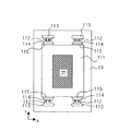
図5は本発明に係る実施例3を示すレチクルステージの微動部を上から見た概略平面図である。本実施例は、光源がKrF、ArFなどレンズを使うことができる露光装置の例であり、微動固定プレート19およびレチクル天板111の中央部には露光光が通過できるように穴が開いており、天地正の構成になっている。
FIG. 5 is a schematic plan view of a fine movement portion of a reticle stage showing Embodiment 3 according to the present invention as viewed from above. This embodiment is an example of an exposure apparatus that can use a lens such as KrF or ArF as a light source, and a hole is formed in the central portion of the fine movement fixed
このように、中央部に大きな穴が開いているレチクル天板111は剛性が低くなるため、図6のようにE字型電磁石12と磁性体板14をY方向の対辺の中央部に配置すると、加減速時に働く電磁継手の吸引力によってレチクル天板111は図中破線のように変形することが考えられる。これを防ぐために、本実施例では図5に示すようにレチクル天板111のY方向の対辺の剛性が高い左右2ヶ所に磁性体板114を配置しており、それと対向するようにE字型電磁石112を微動固定プレート19に配置している。微動固定プレート19にも中央部に大きな穴が開いており、E字型電磁石112は剛性が高い位置に配置していることになる。E字型電磁石112は取付板113を介して微動固定プレート19に取付けられ、磁性体板114は取付板115を介してレチクル天板111の側面に取付けられている。この2対の電磁継手の作用線は、レチクル天板111とこれに装着された部材の全体の重心位置に対して対称の位置にあるのがよい。なお、ここでは図を簡単にするため微動用リニアモータは省略しているが、実施例1のようにレチクル天板111と微動固定プレート19の間に設けてもよいし、実施例2のようにレチクル天板111の側面に電磁継手を避けて配置してもよい。特に本実施例のように、露光光が透過するタイプの露光装置に用いる場合は、レチクルステージの微動部の厚さを小さくすると光源とレンズとの距離が短くなりレンズの径を小さくできるので、微動用リニアモータはレチクル天板111の側面に配置した方が望ましい。
Thus, since the reticle
図7は本発明に係る実施例4を示すレチクルステージの微動部を下から見た概略底面図である。本実施例は、実施例1ないし実施例2と同様天地逆になっている。レチクル天板211のY方向の対辺中央部に磁性体板214が配置され、それと対向するように微動固定プレート29にE字型電磁石212が配置されている。E字型電磁石212は取付板213を介して微動固定プレート29に取付けられ、磁性体板214は取付板215を介してレチクル天板211の側面に取付けられている。E字型電磁石212と磁性体板214との対向する面はレチクル天板211の回転中心を中心とした円弧形状になっている。このような円弧形状にすることによって、E字型電磁石212と磁性体板214がZ軸回りに互いに接触することなく自由に回転できるようになる。また回転に対して両者の隙間の変化がなく同一電流に対して電磁石の発生する吸引力も変化しない。
FIG. 7 is a schematic bottom view of the fine movement portion of the reticle stage showing Embodiment 4 according to the present invention as seen from below. This embodiment is upside down like the first and second embodiments. A
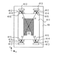
図8は本発明に係る実施例5を示すレチクルステージの微動部を上から見た概略平面図である。本実施例は、実施例3と同様天地正になっている。レチクル天板411のY方向の対辺左右に磁性体板414が配置され、それらと対向するように微動固定プレート49にE字型電磁石412が配置されている。E字型電磁石412は取付板413を介して微動固定プレート49に取付けられ、磁性体板414は取付板415を介してレチクル天板411の側面に取付けられている。E字型電磁石412と磁性体板414との対向する面はすべてレチクル天板411の回転中心を中心とした円弧形状になっている。このような円弧形状にすることによって、実施例4と同様にE字型電磁石412と磁性体板414がZ軸回りに互いに接触することなく自由に回転できるようになる。また回転に対して両者の隙間の変化がなく同一電流に対して電磁石の発生する吸引力も変化しない。さらに、実施例2と同様に電磁継手の吸引力によるレチクル天板411および微動固定プレート49の変形を抑えることができる。
FIG. 8 is a schematic plan view of a fine movement portion of a reticle
図9は本発明に係る実施例6を示すウエハステージの概略斜視図である。この実施例では、ベース定盤51の中央部にスライダ定盤52が搭載され、その周りにXビーム54XをX方向に駆動させる粗動リニアモータの固定子58Xを載せるX定盤53X、およびYビーム54YをY方向に駆動させる粗動リニアモータの固定子58Yを載せるY定盤53Yが搭載されている。Xビーム54Xと、Yビーム54Yとが交差しているところにはXYスライダ56が設けられており、Xビーム54X、およびYビーム54YとXYスライダ56はそれぞれ非接触に支持されており(不図示)、ビームの駆動に伴ってXYスライダ56がスムーズに移動できるようになっている。XYスライダ56の上には、6軸微動ステージ57が載り、さらにウエハチャックを設けてウエハステージを構成している。Yビーム54Yの両端には静圧空気軸受(不図示)を取付けるYフット55Yが設けられており、スライダ定盤52に対して静圧空気軸受によって鉛直方向(Z軸方向)に案内されている。55X,55X’はXビーム54Xの両端に設けられたXフットであり、ステージ定盤52に対して静圧空気軸受(不図示)によって鉛直方向(Z軸方向)に案内されており、図中奥側のXフット55X’はステージ定盤52に取付けられたYガイド52Yに対して静圧空気軸受(不図示)によって水平方向(Y軸方向)にも案内されている。XYスライダ56も底面に設けられた静圧空気軸受(不図示)によってステージ定盤52に対して鉛直方向(Z軸方向)に案内されている。
FIG. 9 is a schematic perspective view of a wafer stage showing a sixth embodiment according to the present invention. In this embodiment, a
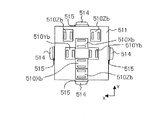
次に、6軸微動ステージ57について説明する。図10(a)は微動ステージ57を上から見た平面図、図10(b)は微動固定プレート59を上から見た平面図、図10(c)はウエハ天板511を下から見た底面図である。微動ステージ57は、微動固定プレート59とウエハ天板511を備えてなり、両者の間には不図示の自重支持ばねが設けられており、ウエハ天板511の自重を支持している。微動用リニアモータは、微動固定プレート59とレチクル天板511に挟まれるようにして配置され、図10(b)において、不図示のコイルを有する固定子510Xa,510Ya,510Zaが微動固定プレート59に、不図示の磁石を有し図10(c)に示すような可動子510Xb,510Yb,510Zbがウエハ天板511に搭載されており、固定子510Xaと可動子510XbでX方向の推力を、固定子510Yaと可動子510YbでY方向の推力を、固定子510Zaと可動子510ZbでZ方向の推力をそれぞれ発生させる。
Next, the 6-axis
ウエハ天板511の周囲4辺側面には取付板515を介して磁性体板514が配置されており、それらと対向するようにコイルを有するE字型電磁石512が微動固定プレート59に取付板513を介して配置されている。これらE字型電磁石512と磁性体板514は対向させることでコイルに電流を流すと両者の間に吸引力が発生し、電磁継手として機能する。つまり、粗動用リニアモータ固定子58X,58Yと、Xフット54XおよびYフット54Yの先端部に取付けられた不図示の可動磁石との間の推力によって、XYスライダ56および微動固定プレート59に加速力が発生するとき、その加速力をウエハ天板511に伝達するためにE字型電磁石512と磁性体板514との間に吸引力を発生させる。E字型電磁石512と磁性体板514との対向する面はウエハ天板511の回転中心を中心とした円弧形状になっている(円弧の径は必ずしもすべて同じでなくてもよい)。このような円弧形状にすることによって、E字型電磁石512と磁性体板514がZ軸回りに互いに接触することなく自由に回転できるようになる。また回転に対して両者の隙間の変化がなく同一電流に対して電磁石の発生する吸引力も変化しない。言うまでもなく、E字型電磁石512と磁性体板514の間に発生する吸引力の作用線はウエハ天板511とそれに装着されたリニアモータ等全体の重心位置を通るのがよい。
A
ウエハステージの微動部の構成は、例えば特開2003−22960号公報に開示されたものがあるが、この場合はE字型電磁石と磁性体板からなる電磁継手は、ウエハ天板の外周側に配置されておらず、中央部に微動固定プレートとウエハ天板に挟まれるように配置されている。このため、E字型電磁石と磁性体板との対向面積を所定の大きさとするためには、本発明よりウエハ天板が大きくなってしまい動的特性が低下してしまう。また、ウエハ天板に取付けられた磁性体板は本発明では剛体と見なせるが、特開2003−22960号公報に記載された発明では磁性体自身の変形で加速力の伝達に遅れが生じる可能性がある。 The configuration of the fine movement portion of the wafer stage is disclosed in, for example, Japanese Patent Application Laid-Open No. 2003-22960. In this case, an electromagnetic coupling composed of an E-shaped electromagnet and a magnetic plate is provided on the outer peripheral side of the wafer top plate. It is not arranged, and is arranged in the center so as to be sandwiched between the fine movement fixing plate and the wafer top plate. For this reason, in order to set the facing area between the E-shaped electromagnet and the magnetic plate to a predetermined size, the wafer top plate becomes larger than in the present invention and the dynamic characteristics are deteriorated. In addition, the magnetic plate attached to the wafer top plate can be regarded as a rigid body in the present invention, but in the invention described in Japanese Patent Application Laid-Open No. 2003-22960, there is a possibility that the transmission of acceleration force may be delayed due to the deformation of the magnetic body itself. There is.
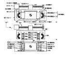
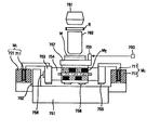
図12は、実施例6に記載したのと実質的に同一構成の位置決め装置を備えるステージをウエハステージとする半導体デバイス製造用の露光装置を示す。 FIG. 12 shows an exposure apparatus for manufacturing semiconductor devices in which a stage including a positioning apparatus having substantially the same configuration as that described in the sixth embodiment is used as a wafer stage.
この露光装置は、半導体集積回路等の半導体デバイスや、マイクロマシン、薄膜磁気ヘッド等の微細なパターンが形成されたデバイスの製造に利用され、原版であるレチクルRを介して基板としての半導体ウエハW上に光源761からの露光エネルギーとしての露光光(この用語は、可視光、紫外光、EUV光、X線、電子線、荷電粒子線等の総称である)を投影系としての投影レンズ(この用語は、屈折レンズ、反射レンズ、反射屈折レンズシステム、荷電粒子レンズ等の総称である)762を介して照射することによって、基板上に所望のパターンを形成している。
This exposure apparatus is used for manufacturing a semiconductor device such as a semiconductor integrated circuit or a device on which a fine pattern is formed, such as a micromachine or a thin film magnetic head, on a semiconductor wafer W as a substrate via a reticle R which is an original plate. A projection lens (this terminology) that uses exposure light (this term is a generic term for visible light, ultraviolet light, EUV light, X-rays, electron beams, charged particle beams, etc.) as the exposure energy from the
この露光装置は、定盤751上にガイド752とリニアモータ固定子721を固設している。リニアモータ固定子721は電磁コイルを、リニアモータ可動子711は永久磁石を有している。リニアモータ可動子711を可動部753として、可動ガイド754に接続し、リニアモータM1の駆動によって可動ガイド754を紙面法線方向に移動させる。可動部753は、定盤751の上面を基準に静圧軸受755で、ガイド752の側面を基準に静圧軸受756で支持される。
In this exposure apparatus, a
可動ガイド754を跨ぐようにして配置した移動ステージ557は静圧軸受758によって支持されている。この移動ステージ757は、実施例6に記載したのと同様の位置決め装置を備え、リニアモータM2によって駆動され、可動ガイド754を基準に移動ステージ757が紙面左右方向に移動する。移動ステージ757の動きは、移動ステージ757に固設したミラー759および干渉計760を用いて計測する。
A moving stage 557 arranged so as to straddle the
移動ステージ757に搭載したチャック上に基板であるウエハWを保持し、光源761、投影光学系762によって、原版であるレチクルRのパターンをウエハW上の各領域にステップアンドリピートもしくはステップアンドスキャンで縮小転写する。
The wafer W, which is a substrate, is held on a chuck mounted on the moving
なお、本発明の位置決め装置は、マスクを使用せずに半導体ウエハ上に回路パターンを直接描画してレジストを露光するタイプの露光装置にも、同様に適用できる。 Note that the positioning apparatus of the present invention can be similarly applied to an exposure apparatus that directly draws a circuit pattern on a semiconductor wafer without using a mask and exposes a resist.
次に、この露光装置を利用した半導体デバイスの製造プロセスを説明する。図13は半導体デバイスの全体的な製造プロセスのフローを示す図である。ステップ1(回路設計)では半導体デバイスの回路設計を行う。ステップ2(マスク作製)では設計した回路パターンに基づいてマスクを作製する。 Next, a semiconductor device manufacturing process using this exposure apparatus will be described. FIG. 13 is a diagram showing a flow of an entire manufacturing process of a semiconductor device. In step 1 (circuit design), a semiconductor device circuit is designed. In step 2 (mask fabrication), a mask is fabricated based on the designed circuit pattern.
一方、ステップ3(ウエハ製造)ではシリコン等の材料を用いてウエハを製造する。ステップ4(ウエハプロセス)は前工程と呼ばれ、上記のマスクとウエハを用いて、上記の露光装置によりリソグラフィ技術を利用してウエハ上に実際の回路を形成する。次のステップ5(組み立て)は後工程と呼ばれ、ステップ5によって作製されたウエハを用いて半導体チップ化する工程であり、アッセンブリ工程(ダイシング、ボンディング)、パッケージング工程(チップ封入)等の組み立て工程を含む。ステップ6(検査)ではステップ5で作製された半導体デバイスの動作確認テスト、耐久性テスト等の検査を行う。こうした工程を経て半導体デバイスが完成し、ステップ7でこれを出荷する。
On the other hand, in step 3 (wafer manufacture), a wafer is manufactured using a material such as silicon. Step 4 (wafer process) is called a pre-process, and an actual circuit is formed on the wafer by using the above-described exposure apparatus and lithography technology using the above-described mask and wafer. The next step 5 (assembly) is called a post-process, which is a process for forming a semiconductor chip using the wafer produced in
上記ステップ4のウエハプロセスは以下のステップを有する。ウエハの表面を酸化させる酸化ステップ、ウエハ表面に絶縁膜を成膜するCVDステップ、ウエハ上に電極を蒸着によって形成する電極形成ステップ、ウエハにイオンを打ち込むイオン打ち込みステップ、ウエハに感光剤を塗布するレジスト処理ステップ、上記の露光装置によって回路パターンをレジスト処理ステップ後のウエハに転写する露光ステップ、露光ステップで露光したウエハを現像する現像ステップ、現像ステップで現像したレジスト像以外の部分を削り取るエッチングステップ、エッチングが済んで不要となったレジストを取り除くレジスト剥離ステップ。これらのステップを繰り返し行うことによって、ウエハ上に多重に回路パターンを形成する。 The wafer process in step 4 includes the following steps. An oxidation step for oxidizing the surface of the wafer, a CVD step for forming an insulating film on the wafer surface, an electrode formation step for forming electrodes on the wafer by vapor deposition, an ion implantation step for implanting ions on the wafer, and applying a photosensitive agent to the wafer A resist processing step, an exposure step for transferring the circuit pattern to the wafer after the resist processing step by the above exposure apparatus, a development step for developing the wafer exposed in the exposure step, and an etching step for scraping off portions other than the resist image developed in the development step A resist stripping step that removes the resist that has become unnecessary after etching. By repeating these steps, multiple circuit patterns are formed on the wafer.
1,51…ベース定盤、2,52…スライダ定盤、302…平面ガイド、52Y…Yガイド、53X…X定盤、3,53Y…Y定盤、4,14,114,214,414,514,614,307…磁性体板、55X,55X’…Xフット、5,55Y…Yフット、6,12,112,212,412,512,612,308…電磁石、54X…Xビーム、54Y…Yビーム、56…XYスライダ、7…可動磁石、8,58X,58Y…粗動リニアモータ固定子、310…送りネジ駆動系、9,19,29,49,59,69…微動固定プレート、10,303…微動リニアモータ、10Xa,10Ya,10Za, 510Xa,510Ya,510Za, 610Xa,610Ya,610Za,305…微動リニアモータ固定子、10Xb,10Yb,10Zb, 510Xb,510Yb,510Zb, 610Xb,610Yb,610Zb,304…微動リニアモータ可動子、11,111,211,411,511,611…天板、301…ステージ、13,15…取付板。
DESCRIPTION OF
Claims (12)
前記第1テーブルに対して移動可能な第2テーブルと、前記第2テーブルを移動させる第2駆動手段と、前記第1テーブルと前記第2テーブルとの間にあって前記第1駆動手段の駆動力に応じて前記第2テーブルに前記第1方向の加速力を伝達する電磁継手とを備える位置決め装置であって、
前記電磁継手は電磁石と該電磁石と対向する磁性体部とを備え、該磁性体部は前記第1方向における前記第2テーブルの前後の側面に少なくとも2対配置されることを特徴とする位置決め装置。 A first table movable with respect to a base table; first driving means for moving the first table in a first direction ;
A second table movable with respect to the first table; a second driving means for moving the second table; and a driving force of the first driving means between the first table and the second table. And a magnetic coupling that transmits the acceleration force in the first direction to the second table.
The electromagnetic coupling includes an electromagnet and a magnetic body portion facing the electromagnet, and the magnetic body portions are arranged in at least two pairs on the front and rear side surfaces of the second table in the first direction . .
前記電磁継手は電磁石と該電磁石と対向する磁性体部とを備え、該磁性体部は前記第1方向における前記第2テーブルの前後の側面に少なくとも2対配置され、
前記2対の磁性体部の各々が受ける電磁力の作用線は該穴の開いていない領域を通ることを特徴とする位置決め装置。 A first table movable with respect to the base table, a first driving means for moving the first table in the first direction, and movable with respect to the first table, with a hole in the center. A second table, a second driving means for moving the second table, and the first table on the second table according to the driving force of the first driving means between the first table and the second table. A positioning device comprising an electromagnetic coupling for transmitting a direction acceleration force,
The electromagnetic coupling includes an electromagnet and a magnetic body portion facing the electromagnet, and the magnetic body portions are disposed in at least two pairs on the front and rear side surfaces of the second table in the first direction,
2. A positioning apparatus according to claim 1, wherein a line of action of electromagnetic force received by each of the two pairs of magnetic parts passes through a region where the hole is not formed.
前記電磁継手は電磁石と該電磁石と対向する磁性体部とを備え、該磁性体部は前記第1方向における前記第2テーブルの前後の側面に少なくとも2対配置され、
前記2対の磁性体部の各々が受ける電磁力の作用線が、前記第2テーブルとこれに装着された部材の全体の重心位置に対して対称の位置にあることを特徴とする位置決め装置。 A first table movable with respect to a base table; a first driving means for moving the first table in a first direction; a second table movable with respect to the first table; and the second table. A second driving means for moving, and an electromagnetic coupling between the first table and the second table for transmitting an acceleration force in the first direction to the second table according to the driving force of the first driving means; A positioning device comprising:
The electromagnetic coupling includes an electromagnet and a magnetic body portion facing the electromagnet, and the magnetic body portions are disposed in at least two pairs on the front and rear side surfaces of the second table in the first direction,
The two pairs of magnetic portions electromagnetic force line of action, each receiving of the position characterized in that it is in a position symmetrical with respect to the center of gravity position of the entire second table and which in the mounted member Decision device.
前記電磁継手は電磁石と該電磁石と対向する磁性体部とを備え、該磁性体部は前記第1方向における前記第2テーブルの前後の側面に少なくとも2対配置され、
前記電磁石と前記磁性体部が対向する面は、前記第2テーブルの回転中心を中心とする円弧状であることを特徴とする位置決め装置。 A first table movable with respect to a base table; a first driving means for moving the first table in a first direction; a second table movable with respect to the first table; and the second table. A second driving means for moving; and an electromagnetic coupling between the first table and the second table for transmitting an acceleration force in the first direction to the second table in accordance with a driving force of the first driving means. A positioning device comprising:
The electromagnetic coupling includes an electromagnet and a magnetic body portion facing the electromagnet, and the magnetic body portions are disposed in at least two pairs on the front and rear side surfaces of the second table in the first direction,
Surface on which the magnetic body and the electromagnet are opposed, the position-decided Me device you wherein a second table arcuate shape about the rotational center of the.
移動可能な第1テーブルと、前記第1テーブルを第1方向に移動させる第1駆動手段と、前記第1テーブルに対して移動可能であり、露光光を通過させるための穴が形成された第2テーブルと、前記第2テーブルを前記第1テーブルに対して移動させる第2駆動手段と、前記第1駆動手段の駆動力に応じて前記第2テーブルに前記第1方向の加速力を伝達する電磁継手とを備え、A movable first table, first driving means for moving the first table in a first direction, and a first table that is movable with respect to the first table and has a hole for allowing exposure light to pass therethrough. Two tables, a second driving means for moving the second table relative to the first table, and an acceleration force in the first direction to the second table according to the driving force of the first driving means. With electromagnetic coupling,
前記電磁継手は電磁石と該電磁石と対向する磁性体部とを備え、該磁性体部は前記第1方向における前記第2テーブルの前後の側面に少なくとも2対配置され、前記2対の磁性体部の各々が受ける電磁力の作用線は前記穴の開いていない領域を通ることを特徴とする露光装置。The electromagnetic coupling includes an electromagnet and a magnetic body portion facing the electromagnet, and the magnetic body portions are disposed at least two pairs on the front and rear side surfaces of the second table in the first direction, and the two pairs of magnetic body portions An exposure apparatus characterized in that the line of action of the electromagnetic force received by each of the two passes through a region where the hole is not opened.
Priority Applications (2)
| Application Number | Priority Date | Filing Date | Title |
|---|---|---|---|
| JP2004048921A JP4307288B2 (en) | 2004-02-25 | 2004-02-25 | Positioning device |
| US11/063,576 US7336344B2 (en) | 2004-02-25 | 2005-02-24 | Positioning system, exposure apparatus using the same, and device manufacturing method |
Applications Claiming Priority (1)
| Application Number | Priority Date | Filing Date | Title |
|---|---|---|---|
| JP2004048921A JP4307288B2 (en) | 2004-02-25 | 2004-02-25 | Positioning device |
Publications (3)
| Publication Number | Publication Date |
|---|---|
| JP2005243751A JP2005243751A (en) | 2005-09-08 |
| JP2005243751A5 JP2005243751A5 (en) | 2007-04-12 |
| JP4307288B2 true JP4307288B2 (en) | 2009-08-05 |
Family
ID=34858221
Family Applications (1)
| Application Number | Title | Priority Date | Filing Date |
|---|---|---|---|
| JP2004048921A Expired - Fee Related JP4307288B2 (en) | 2004-02-25 | 2004-02-25 | Positioning device |
Country Status (2)
| Country | Link |
|---|---|
| US (1) | US7336344B2 (en) |
| JP (1) | JP4307288B2 (en) |
Cited By (1)
| Publication number | Priority date | Publication date | Assignee | Title |
|---|---|---|---|---|
| US8642134B2 (en) | 2006-12-22 | 2014-02-04 | Sony Corporation | Coated-product with marking, process for manufacturing the same, and enclosure for electronic apparatus |
Families Citing this family (20)
| Publication number | Priority date | Publication date | Assignee | Title |
|---|---|---|---|---|
| JP2004228473A (en) * | 2003-01-27 | 2004-08-12 | Canon Inc | Movable stage device |
| JP2005294468A (en) * | 2004-03-31 | 2005-10-20 | Canon Inc | Positioner device, aligner and device manufacturing method |
| JP2007329435A (en) | 2006-06-09 | 2007-12-20 | Canon Inc | Stage apparatus, exposure apparatus, and manufacturing method of device |
| JP2008004647A (en) * | 2006-06-20 | 2008-01-10 | Canon Inc | Positioning apparatus, exposure apparatus, and device manufacturing method |
| JP2008078499A (en) * | 2006-09-22 | 2008-04-03 | Canon Inc | Supporting apparatus, exposure system, and manufacturing method of device |
| JP2008172137A (en) * | 2007-01-15 | 2008-07-24 | Canon Inc | Positioning apparatus and photolithography machine |
| US7649333B2 (en) * | 2007-01-15 | 2010-01-19 | Asm Assembly Automation Ltd. | Active damping device for a positioning stage |
| CN101611470B (en) | 2007-03-05 | 2012-04-18 | 株式会社尼康 | Moving body apparatus, apparatus for forming pattern, method of forming pattern, method of producing device, method of producing moving body apparatus, and method of driving moving body |
| JP5013941B2 (en) * | 2007-04-19 | 2012-08-29 | キヤノン株式会社 | Stage apparatus, exposure apparatus, and device manufacturing method |
| JP2009016385A (en) * | 2007-06-29 | 2009-01-22 | Canon Inc | Stage apparatus, exposure apparatus, and method of manufacturing device |
| JP4853836B2 (en) * | 2007-09-19 | 2012-01-11 | 株式会社安川電機 | Precision fine positioning apparatus and fine positioning stage equipped with the same |
| JP5180555B2 (en) * | 2007-10-04 | 2013-04-10 | キヤノン株式会社 | Positioning apparatus, exposure apparatus, and device manufacturing method |
| TW200935380A (en) * | 2008-02-01 | 2009-08-16 | Au Optronics Corp | Display device and driving method thereof |
| TWI359344B (en) * | 2008-03-25 | 2012-03-01 | Univ Nat Taiwan | A six degree of freedom precise positioning system |
| KR101365078B1 (en) * | 2011-01-28 | 2014-02-20 | 주식회사 에스에프에이 | Vacuum deposition system |
| EP2492928A3 (en) | 2011-02-22 | 2017-08-30 | ASML Netherlands BV | Electromagnetic actuator, stage apparatus and lithographic apparatus |
| CN106569396B (en) * | 2011-09-12 | 2018-10-19 | 迈普尔平版印刷Ip有限公司 | Target locating set |
| CN104749897B (en) * | 2013-12-27 | 2017-06-27 | 上海微电子装备有限公司 | A kind of litho machine sports platform support platform |
| JP6900284B2 (en) * | 2017-09-27 | 2021-07-07 | 株式会社Screenホールディングス | Drawing device and drawing method |
| WO2023217553A1 (en) * | 2022-05-12 | 2023-11-16 | Asml Netherlands B.V. | A movable stage for a lithographic apparatus |
Family Cites Families (5)
| Publication number | Priority date | Publication date | Assignee | Title |
|---|---|---|---|---|
| JP3745167B2 (en) | 1998-07-29 | 2006-02-15 | キヤノン株式会社 | Stage apparatus, exposure apparatus, device manufacturing method, and stage driving method |
| US6720983B1 (en) * | 2000-01-05 | 2004-04-13 | Hewlett-Packard Development Company, L.P. | Digital feedback display panel for communicating computer status information |
| JP2003022960A (en) | 2001-07-09 | 2003-01-24 | Canon Inc | Stage unit and its driving method |
| US6597435B2 (en) * | 2001-10-09 | 2003-07-22 | Nikon Corporation | Reticle stage with reaction force cancellation |
| US7034474B2 (en) * | 2004-02-09 | 2006-04-25 | Nikon Corporation | Auto-calibration of attraction-only type actuator commutations |
-
2004
- 2004-02-25 JP JP2004048921A patent/JP4307288B2/en not_active Expired - Fee Related
-
2005
- 2005-02-24 US US11/063,576 patent/US7336344B2/en active Active
Cited By (1)
| Publication number | Priority date | Publication date | Assignee | Title |
|---|---|---|---|---|
| US8642134B2 (en) | 2006-12-22 | 2014-02-04 | Sony Corporation | Coated-product with marking, process for manufacturing the same, and enclosure for electronic apparatus |
Also Published As
| Publication number | Publication date |
|---|---|
| US20050185167A1 (en) | 2005-08-25 |
| US7336344B2 (en) | 2008-02-26 |
| JP2005243751A (en) | 2005-09-08 |
Similar Documents
| Publication | Publication Date | Title |
|---|---|---|
| JP4307288B2 (en) | Positioning device | |
| US7348695B2 (en) | Linear motor, moving stage system, exposure apparatus, and device manufacturing method | |
| US6271606B1 (en) | Driving motors attached to a stage that are magnetically coupled through a chamber | |
| JP4639517B2 (en) | Stage apparatus, lithography system, positioning method, and stage apparatus driving method | |
| US8009275B2 (en) | Movable stage apparatus | |
| US6313550B1 (en) | Coil mounting and cooling system for an electric motor | |
| JP2001228275A (en) | Stage assembly for exposure device | |
| US6603531B1 (en) | Stage assembly including a reaction assembly that is connected by actuators | |
| JP2005046941A (en) | Stage device with cable jogging unit | |
| JP4298547B2 (en) | Positioning apparatus and exposure apparatus using the same | |
| US6597435B2 (en) | Reticle stage with reaction force cancellation | |
| JP2007329435A (en) | Stage apparatus, exposure apparatus, and manufacturing method of device | |
| US20030173833A1 (en) | Wafer stage with magnetic bearings | |
| JP2004364392A (en) | Linear motor, stage equipment comprising it, exposure system and process for fabricating device | |
| JP2005142501A (en) | Stage apparatus, aligner, and method of manufacturing device | |
| JP2007258356A (en) | Stage equipment | |
| JP2005209670A (en) | Magnetic levitation device | |
| JP2008182210A (en) | Stage apparatus, exposure equipment, and device manufacturing method | |
| JP2010262969A (en) | Stage apparatus, exposure apparatus using the same, and device manufacturing method | |
| US6844694B2 (en) | Stage assembly and exposure apparatus including the same | |
| US20030218732A1 (en) | Stage assembly including a reaction assembly | |
| US7738114B2 (en) | Exposure apparatus configured to minimize effects of mechanism for measuring stage position on peripheral mechanism and device-manufacturing method | |
| JP2004281654A (en) | Drive mechanism, aligner employing it, and process for fabricating device | |
| JP2008172137A (en) | Positioning apparatus and photolithography machine | |
| US7221433B2 (en) | Stage assembly including a reaction assembly having a connector assembly |
Legal Events
| Date | Code | Title | Description |
|---|---|---|---|
| A521 | Request for written amendment filed |
Free format text: JAPANESE INTERMEDIATE CODE: A523 Effective date: 20070223 |
|
| A621 | Written request for application examination |
Free format text: JAPANESE INTERMEDIATE CODE: A621 Effective date: 20070223 |
|
| A977 | Report on retrieval |
Free format text: JAPANESE INTERMEDIATE CODE: A971007 Effective date: 20080528 |
|
| A131 | Notification of reasons for refusal |
Free format text: JAPANESE INTERMEDIATE CODE: A131 Effective date: 20080604 |
|
| A521 | Request for written amendment filed |
Free format text: JAPANESE INTERMEDIATE CODE: A523 Effective date: 20080804 |
|
| TRDD | Decision of grant or rejection written | ||
| RD01 | Notification of change of attorney |
Free format text: JAPANESE INTERMEDIATE CODE: A7421 Effective date: 20090406 |
|
| A01 | Written decision to grant a patent or to grant a registration (utility model) |
Free format text: JAPANESE INTERMEDIATE CODE: A01 Effective date: 20090415 |
|
| A01 | Written decision to grant a patent or to grant a registration (utility model) |
Free format text: JAPANESE INTERMEDIATE CODE: A01 |
|
| A61 | First payment of annual fees (during grant procedure) |
Free format text: JAPANESE INTERMEDIATE CODE: A61 Effective date: 20090428 |
|
| R150 | Certificate of patent or registration of utility model |
Free format text: JAPANESE INTERMEDIATE CODE: R150 Ref document number: 4307288 Country of ref document: JP Free format text: JAPANESE INTERMEDIATE CODE: R150 |
|
| FPAY | Renewal fee payment (event date is renewal date of database) |
Free format text: PAYMENT UNTIL: 20120515 Year of fee payment: 3 |
|
| FPAY | Renewal fee payment (event date is renewal date of database) |
Free format text: PAYMENT UNTIL: 20120515 Year of fee payment: 3 |
|
| FPAY | Renewal fee payment (event date is renewal date of database) |
Free format text: PAYMENT UNTIL: 20130515 Year of fee payment: 4 |
|
| FPAY | Renewal fee payment (event date is renewal date of database) |
Free format text: PAYMENT UNTIL: 20140515 Year of fee payment: 5 |
|
| LAPS | Cancellation because of no payment of annual fees |


