EP1582812A1 - Grille d'incinération à gradins fixes refroidis à l'eau - Google Patents
Grille d'incinération à gradins fixes refroidis à l'eau Download PDFInfo
- Publication number
- EP1582812A1 EP1582812A1 EP05290724A EP05290724A EP1582812A1 EP 1582812 A1 EP1582812 A1 EP 1582812A1 EP 05290724 A EP05290724 A EP 05290724A EP 05290724 A EP05290724 A EP 05290724A EP 1582812 A1 EP1582812 A1 EP 1582812A1
- Authority
- EP
- European Patent Office
- Prior art keywords
- wall
- combustion
- module
- chamber
- grid
- Prior art date
- Legal status (The legal status is an assumption and is not a legal conclusion. Google has not performed a legal analysis and makes no representation as to the accuracy of the status listed.)
- Granted
Links
Images


Classifications
-
- F—MECHANICAL ENGINEERING; LIGHTING; HEATING; WEAPONS; BLASTING
- F23—COMBUSTION APPARATUS; COMBUSTION PROCESSES
- F23H—GRATES; CLEANING OR RAKING GRATES
- F23H7/00—Inclined or stepped grates
- F23H7/06—Inclined or stepped grates with movable bars disposed parallel to direction of fuel feeding
- F23H7/08—Inclined or stepped grates with movable bars disposed parallel to direction of fuel feeding reciprocating along their axes
-
- F—MECHANICAL ENGINEERING; LIGHTING; HEATING; WEAPONS; BLASTING
- F23—COMBUSTION APPARATUS; COMBUSTION PROCESSES
- F23G—CREMATION FURNACES; CONSUMING WASTE PRODUCTS BY COMBUSTION
- F23G5/00—Incineration of waste; Incinerator constructions; Details, accessories or control therefor
- F23G5/002—Incineration of waste; Incinerator constructions; Details, accessories or control therefor characterised by their grates
-
- F—MECHANICAL ENGINEERING; LIGHTING; HEATING; WEAPONS; BLASTING
- F23—COMBUSTION APPARATUS; COMBUSTION PROCESSES
- F23H—GRATES; CLEANING OR RAKING GRATES
- F23H3/00—Grates with hollow bars
- F23H3/02—Grates with hollow bars internally cooled
-
- F—MECHANICAL ENGINEERING; LIGHTING; HEATING; WEAPONS; BLASTING
- F23—COMBUSTION APPARATUS; COMBUSTION PROCESSES
- F23H—GRATES; CLEANING OR RAKING GRATES
- F23H2900/00—Special features of combustion grates
- F23H2900/03021—Liquid cooled grates
Definitions
- the invention relates to a module intended to be associated with other modules of similar geometry to form a grate for waste incineration furnace a grid comprising a plurality of such modules, as well as a installation for the incineration of household refuse.
- An installation of this type includes an oven in which is provided a grid on which are placed the garbage during their combustion.
- the garbage to be incinerated is brought into the furnace, upstream of the grid, then gradually moved on the grid downstream, the grid being inclined towards the low compared to the horizontal in the direction of progression of the garbage.
- Grids generally consist of a plurality of modules of analog geometry placed one after the other in a staggered manner vertically and horizontally, so that the grid looks like a succession of "tiers".
- Each module includes several elements forming on the one hand a fixed part, serving in particular as support for garbage during their combustion, and secondly a mobile part arranged to push garbage from the fixed part of the module under consideration to the fixed part of the adjacent module immediately downstream.
- Incineration grids of this type are already known.
- the different parts of the module are each consisting of a simple metal plate, and the module is cooled by a circulation of air.
- This mode of cooling generally gives satisfaction for furnaces of low to medium capacity: around 2.5 to 6 tonnes of garbage treated with hour for example, and a lower ICP (lower calorific value of waste) at 11 000 kJ / kg.
- garbage PCI tends to increase, and can reach 15,000 kJ / kg.
- the air cooling does not allow to lower the temperature of the modules, which can reach 400 to 550 ° C or more. This results in a degradation of the modules, and therefore the grid, which results in particular in a loss of the quality of the combustion, problems of mechanical strength, and a greatly diminished life.
- this type of air-cooled rack has an allowable heating value. too limited, and does not meet the growing demands in terms of the capacity of treated waste and the quality of the combustion.
- the different parts of the module each form a hollow compartment in which a liquid circulates cooling, for example water.
- the cooling of a grid module is more efficient than the air cooling provided in the first known embodiment.
- the capacity admissible by the furnace provided with this grid is therefore more important.
- the hoses are positioned under the grid in an area difficult to inspect (circulating air temperature 130 ° C approximately, risk of falling incandescent dusts or metals in fusion, etc.).
- the object of the invention is to provide a grate module for a furnace for incineration of garbage that has a significant allowable capacity and is provided with a efficient cooling system and little binding.
- the moving part moves towards its deployed position, pushing the garbage along the first wall of combustion down to the downstream end of this first combustion wall, that is to say until the break of slope. Then the garbage falls and slips along the second combustion wall, because of its inclination, while that the moving part moves to its retracted position.
- the mobile part For most of its travel cycle (over 70% of duration of a cycle, or even more than 80%, or even more than 90%), the mobile part is located entirely under the adjacent module located immediately upstream, and is therefore protected and less exposed to heat.
- the invention thus makes it possible to dispense with liquid transport hoses cooling, and all the associated disadvantages.
- the length of the second combustion wall is included between about 50% and 150% of the length of said first wall of combustion, and is therefore relatively large compared to the total length of the module.
- the stroke of the moving part is relatively small. After an initial push, the garbage falls and turns naturally along the second combustion wall, and the thrust means can therefore return to its retracted position.
- the cooling system of the module comprises a third associated wall under the first combustion wall so as to form between said first and third walls a first chamber, and a fourth associated wall under the second wall of combustion, so as to form between said second and fourth walls a second bedroom separate from the first bedroom.
- At least one element comprises a side wall projecting from the upper wall, the lower wall of the element being welded to the part bottom of the side wall.
- a partition wall may extend inside said chamber between a port and an exit port, over substantially the entire height of the chamber and over a distance intended to guide the flow of liquid in said chamber.
- the exit port of the first chamber is connected to the port of entry of the first chamber, respectively the second.
- the second combustion wall may comprise a succession of 4 to 7 steps each comprising a substantially flat portion and parallel to the first combustion wall and a substantially flat portion and perpendicular to the first combustion wall, so as to form a staircase.
- a chamber comprises a port of entry and a coolant outlet port, the port of entry comprising a duct opening into the room under and in the immediate vicinity a portion of the first or second combustion wall for be placed substantially horizontally in the oven.
- a combustion air supply system can be provided, this system having at least one air passage channel passing through the first element substantially vertically and opening on the one hand through an opening formed in the lower wall and on the other hand by a hole in the upper wall, substantially horizontal, of the first element, the channel presenting, throughout its height, a horizontal section of dimensions greater than or equal to those of the orifice, the channel widening from the face upper part of the element towards the lower wall of said element at least on a part of the height of the canal.
- the channel widening downwards (continuously, in the manner of a cone by example, or discontinuously, forming degrees), its clogging by garbage is more difficult, these can fall without being blocked in the canal.
- the combustion air supply system may further comprise at least one air channel passing through the second element from bottom to top, and opening through an orifice in a substantially vertical portion of the upper wall of said second element.
- the holes being made in a vertical wall, and the movement of thrust of garbage tending to remove garbage from these orifices, the risk of capping is weak.
- At least one of the elements comprises at least a first projection extending from a first side wall of said element outward, and at least one second projection extending from a second side wall of said element towards the outside, the upper face of the second projection being shifted downwards with respect to the upper face of the first projection a distance greater than the height of the first projection, so that when two substantially identical elements are associated laterally, the first projection of an element covers the second projection of the adjacent element.
- the grid allows the lateral expansion of the elements, and only the air passages strictly necessary.
- the invention relates to an oven rack incineration process comprising a plurality of modules such as than previously described.
- the modules are arranged so that their first combustion wall is placed substantially horizontally in the furnace and that the downstream end of the second combustion wall of a module is placed substantially in line with the upstream end of the first wall of combustion of the adjacent module located downstream, above the thrust means garbage from said adjacent module so as to form a succession of entertained.
- a step comprises a plurality of modules substantially identical laterally associated with each other.
- the second chambers of the modules of a grid step are connected in series by their ports of entry and exit, at least partly, the first chambers of the modules of a tier of the grid are connected in series their ports of entry and exit, at least in part, the port of exit of the second chamber of a given module being connected to the port of entry of the first chamber of said module.
- the invention relates to an installation for the incineration of household refuse, comprising at least one oven in which is provided such a grid, means of supply of household waste in the oven, upstream of the grid, means for collecting residues from incineration, downstream of the gate, and means for conveying a liquid of cooling of the modules of the grid.
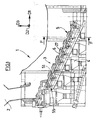
- Figure 1 represents an installation for the incineration of household refuse.
- the installation includes an oven 1 in which the garbage to be incinerated is fed, upstream, via feed means such as a feed hopper 2.
- the installation includes means for collecting residues from incineration downstream, as well as means of effluents - especially gases - from combustion.
- the oven comprises a grid 3 generally inclined downwards with respect to horizontally, from upstream to downstream of the oven 1. Garbage, brought to the grid 3 upstream, are gradually incinerated and moved to Grid 3 to downstream.
- the oven 1 also comprises several air distribution hoppers 4 located under the grid 3, and intended to provide the necessary air for the combustion of garbage. Means for conveying a coolant to and from from grid 3 are also provided.
- the grid may have a length of 8 to 10 m, depending on its capacity, and a width of 3 to 6 m approximately.
- the grid 3 comprises a plurality of modules 5 associated with each other offset vertically and horizontally, so that grid 3 is presents as a succession of "tiers".
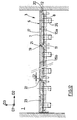
- a step includes himself several substantially identical modules associated laterally with each other. others (see Figure 12).
- the number of bleachers can vary from 6 to 9, depending on the oven capacity 1.
- direction D1 corresponding to the direction of progression of the garbage
- substantially vertical direction D3 a direction corresponding to the direction of progression of the garbage
- D2 a direction orthogonal to D1 and D2.
- the terms “length”, “upstream”, “downstream” will be used for reference in direction D1
- the terms “width”, “transversal”, “lateral” will be employees with reference to the D2 direction
- the term “height” will be used with reference to direction D3.
- the grid 3 is composed of three types of different modules: the module or modules located upstream, the module or modules located furthest downstream, and modules located in the middle. We will be interested in following the modules located in the middle of the grid 3.
- a module 5 is now described with reference to FIGS. 2 to 11.
- Module 5 comprises a fixed part, serving in particular as a support for garbage during their combustion, and a moving part arranged to push the garbage from the fixed part of the module considered towards the fixed part of the module adjacent immediately downstream.
- the fixed part comprises a first element 6, substantially parallelepipedic, having an upper wall 7, a lower wall 8, an upstream wall 9, a downstream wall 10, a left lateral wall 11 and a right lateral wall 12.
- the first element 6 is placed in the oven 1 so that its upper wall 7 is substantially horizontal, and its side walls 11, 12 are substantially parallel to the direction D1.
- the width of the first element is of the order of 25 cm, its length of the order of 50 cm, and its thickness close to 5 cm.
- a wall separation 13 extending parallel to D1 from the downstream wall 10 to the upstream wall 9, over a distance of the order of three quarters of the length of the first element 6, substantially halfway between the side walls 11, 12.
- first portion of the partition wall 13, extending from the downstream wall 10 about one-third of the length of the first element 6, is formed of a simple plate 14.
- a second portion, extending from the first portion to the upstream wall 9, is formed of two parallel plates 15a, 15b disposed opposite one another and associated by their downstream ends and upstream so as to form a channel 60 of rectangular horizontal section.
- the plates 15a, 15b are spaced apart by a distance of the order of 1 cm.
- the upper wall 7 comprises two oblong orifices 16, of a length adjacent to 6 cm, opening into the space between the plates 15a, 15b.
- the width of the orifices 16 is of the order of 6 mm at the upper face 17 of the upper wall 7, the width of the channel 60 gradually increasing when we move downwards, the inner face of the orifice joining the face 18a, 18b of the plates 15a, 15b ( Figure 5).
- the first element 6 includes a first projection 19 extending from the right lateral wall 12 towards the outside, substantially in extension of the upper wall 7, over the entire length of said first element 6.
- the first projection 19 has a cross section substantially rectangular.
- the width of the first projection 19 is of the order of 1.5 cm.
- the height of the first projection, between its upper face located substantially in the same plane as the upper face 17 of the upper wall 7 of the first element 6, and its lower face 20, is of the order of 1 cm.
- a second projection 21 extends from the left side wall 11 towards outside, but is not continuous over the entire length of the first element 6. From the upstream wall 9 to the downstream wall 10, one successively encounters: a first portion 21a of the second projection 21, of length close to 30% of the total length of the first element 6, an interruption of the second projection 21 (about 15% of the total length of the first element 6), a second portion 21b of the second projection 21 (about 10% of the length of the first element 6), an interruption of the second projection 21 (approximately 15% of the total length of the first element 6), a third portion 21 c of the second projection 21 (about 25% of the total length of the first element 6), and an interruption of the second projection 21.
- the second projection 21 has a cross section substantially rectangular, a height of about 1 cm and a width of about 1.5 cm.
- the second projection 21 is shifted downward relative to the first projection 19, so that the upper face 22 of the second projection 21 is located substantially in the same plane as the lower face 20 of the first projection 18.
- the walls 7, 9 to 14, 15a, 15b and the projections 19, 21 are made of a single piece of steel by molding.
- the bottom wall 8 is a sheet metal plate having the general shape of a U, welded in the lower part of the first element 6 to the upstream and downstream walls 9 and 9, as well as, on the one hand, between the left side wall 11 and the plate 15a and, on the other hand, between the right side wall 12 and the plate 15b.
- a first U-shaped chamber 23 is formed between the wall lower 8 and the upper walls 7, lateral 11, 12 and upstream 9, downstream 10.
- the channel formed between the plates 15a and 15b is devoid of bottom (see Figure 5).
- the bottom wall 8 has an inlet 24 and an outlet 25 located on either side of the plate 14.
- a conduit 26 is welded in each of these orifices 24, 25 so as to form an input port and an output port towards and from the first chamber 23.
- the conduit 26 opens into the interior of the first chamber 23 under and in the immediate vicinity of the upper wall 7, to a distance of less than 1 cm, for example 8 mm.
- the fixed part also comprises a second element 27 comprising a upper wall 28, a lower wall 29, an upstream wall 30 and a wall downstream 31 substantially parallel to D2, a left side wall 32 and a wall lateral right 33 substantially parallel to D1.
- the width of the second element is of the order of 25 cm, its length of the order of 50 cm, and its height close 30 cm.
- the upper wall 28 of the second element 27 comprises a succession of 5 steps each comprising a portion 28a substantially flat and parallel to the upper wall 7 of the first element 6 and a portion 28b substantially plane and perpendicular to the upper wall 7 of the first element 6.
- the wall upper 28 thus has the general shape of a staircase, inclined overall an angle ⁇ of the order of 23 °.
- a partition wall extending parallel to D1 from the downstream wall 31 towards the upstream wall 30, over a distance of the order of 85% of the length of the second element 27 substantially at half distance from the side walls 32, 33.
- the wall of separation is formed of two plates 34a, 34b spaced apart from one another distance close to 1 cm and associated with their upstream end.
- Each of the substantially vertical portions 28b of the upper wall 28 has an orifice 35, extending over substantially the entire height of said portion 28b, of width corresponding to the spacing between the plates 34a, 34b, and opening into the space between said plates 34a, 34b ( Figure 9).
- the second element 27 comprises a series of first projections 36 each extending from the right side wall 33 outwards, substantially in extension of a substantially horizontal portion 28a of the upper wall 28, from the downstream end of said portion 28a to and slightly beyond the upstream end of said portion 28a.
- Each of the first projections 36 has a cross section substantially rectangular and a width of the order of 1.5 cm.
- the second element 27 further comprises a series of second projections 39 each extending from the left side wall 32 outwardly.
- Each second projections 39 has a cross-section substantially rectangular, a height of about 1 cm and a width of about 1.5 cm.
- Each of the second projections 39 extends parallel to a portion 28a substantially horizontal of the upper wall 28, not an extension of it, but shifted downward, so that the upper face 40 of the second projection 39 is located substantially in the same plane as the lower face 38 of the first projection 36.
- each of the second projections 39 extends from the downstream end of said portion 28a to and slightly beyond the upstream end of said portion 28a.
- the second element 27 thus has a left horizontal protrusion 39 and a right projection 36 at each of its steps, and is devoid of any protrusion vertical (parallel to the vertical portion 28b of each step).
- the vertical portion 28b of the step lower section has a straight vertical protrusion 36 discontinuous extending towards the outside substantially in extension of the vertical portion 28b, and a left vertical protrusion 39 discontinuous extending outward, being offset upstream, so that the upstream face 41 of the right projection 36 is located substantially in the same plane as the downstream face 42 of the projection left 39.
- the lower wall 29 of the second element 27 has, in section longitudinal, a shape similar to that of the upper wall (succession of horizontal portions 29a and vertical portions 29b forming the steps of a staircase).
- the bottom wall 29 has the general shape a U extending between the upstream 30 and downstream walls 31 and, on the one hand, between the left side wall 32 and the plate 34a and, on the other hand, between the wall right side 33 and the plate 34b.
- the channel formed between the plates 34a, 34b is devoid of background (see Figure 8).
- a second U-shaped chamber 43 is thus formed between the wall lower 29 and the upper walls 28, lateral 32, 33 and upstream 30, downstream 31.
- the bottom wall 29 includes a central zone 44 extending over the entire width of the second element 27, as well as an upstream zone 45 and a downstream zone 46 extending, over the entire width of the second element 27, since a end of the central zone towards, respectively, the upstream wall 30 and the wall downstream 31.
- the walls 28, 30 to 33, 34a, 34b, the central zone 44, as well as the projections 36, 39 are made of a single piece of steel by molding, with the help of a core.
- the upstream zone 45 and the downstream zone 46 are sheet metal plates welded in lower part of the second element 27, between the central zone 44, the walls lateral 32, 33 and the upstream wall 30, respectively downstream 31.
- the upstream zone 45 of the lower wall 29 of the second element 27 presents a inlet port 47 and an outlet port 48 located on either side of the plates 34a, 34b, in a horizontal portion of said bottom wall 29.
- a conduit 26 is welded in each of these orifices 47, 48 so as to form a port of entry and an exit port to and from the second chamber 43.
- the conduit 26 opens into the second chamber 43 under and at immediate vicinity of the horizontal portion 28a of the upper wall 28 located the most upstream, at a distance of less than 1 cm, for example 8 mm.
- the air bubble created at the outlet of the conduit 26 is of reduced dimensions.
- it is located in the upper part of the second element 27, that is to say in its least hot part, which limits the problems related to bad cooling.
- the moving part 51 of the module 5 is now described (see FIG. 2).
- the movable portion 51 comprises an upper wall 52 substantially rectangular, from which project, upstream, an upstream wall 53, a wall downstream 54 inclined relative to the horizontal of an angle ⁇ between 60 and 80 ° approximately, and side walls.
- the movable part 51 is placed in the oven 1 so that its upper wall 52 is substantially horizontal, and its side walls substantially parallel at D1 and in the same planes as the side walls 11, 12 of the first element 6.
- the lower face of the movable part 51 cooperates with the upper face 17 of the upper wall 7 of the first element 6.
- the width of the moving part 51 is of the order of 25 cm, its length of the order 60 cm, and its thickness close to 10 cm.
- a movement cycle breaks down as follows: the part 51 is in the retracted position for at least 100 seconds, and moves to its deployed position, then from its deployed position to its position retracted for about 10 seconds.
- the moving part 51 of the module 5 does not form an inner chamber, and is without a liquid cooling system, this part being simply cooled by a circulation of air.
- Two adjacent modules 5 are arranged so that, on the one hand, the downstream wall 31 of the second element 27 of the upper module 5 is placed substantially at right - or slightly offset downstream - from the upstream wall 9 of the first element 6 of the lower module 5 and, on the other hand, the second element 27 of the upper module 5 is located above the moving part 51 of the module 5 inferior.
- the clearance j1 between the lower face of the second element 27 of the module 5 upper and the upper face 56 is of the order of 6 mm.
- the first elements 6 are placed so that the upper faces 17 of their upper walls 7 are located substantially in the same plane.
- the first projection 19 of an element 6 then cooperates with the second projection 21 of the adjacent element 6, since the lower face 20 of a first projection 19 is located substantially in the same plane as the upper face 22 of a second projection 21.
- a protrusion may rest on the adjacent projection. In a variant, there may be a very small vertical clearance between these two projections.
- the skin temperature of the first element 6 is the order of 80 to 85 ° C, the dilation of each of the first elements 6 being limited to about 0.3 mm due to cooling efficiency.
- the skin temperature can reach 500 ° C and the expansion 1.7 mm by first element 6. The value of j2 makes it possible to face this situation.
- first elements 6 located at the lateral ends of a tier can have different lateral shapes (no projections for example).
- the lateral association of the second elements 27 is carried out according to the same principle, by cooperation of the first and second projections 36, 39 with lateral expansion play.
- an air passage between two of the second adjacent elements 27, perpendicular to each vertical portions 28b of the upper wall 28, between two projections 36, 39 consecutive is planned (see the arrows shown in Figure 11).
- Garbage, brought upstream of the grid 3, are at the end of a certain times arranged on the upper wall 7 of the first element 6 of the module 5 located furthest upstream, the corresponding moving part 51 being in position retracted. After a defined period of time, the moving part 51 is moved towards its deployed position, pushing the garbage downstream.
- the quality of the combustion depends, among other things, on the quantity of air injected. This quantity varies according to the amount of garbage incinerated, the PCI, and the area of the oven 1: the oxygen requirement is medium in areas where occurs essentially a drying of the waste (evaporation of the water contained), important in areas of active combustion, and weak in end zones combustion (to have a minimum unburnt rate).
- the system of Air distribution must therefore adapt to different situations.
- the surface air passages to predict is of the order of 40 cm2 per module 5 (in the embodiment shown, and without taking into account the passages between modules adjacent laterally).
- the breakdown can be as follows: about 50% of the area provided in the second element 27, about 25% of the area provided in the first element 6, and about 25% of the area obtained via the game j1.
- the modules 5 are cooled on the one hand by air circulation (moving parts 51) and secondly by circulation of a coolant in the first and second chambers 23, 43.
- the coolant may be water - or any suitable liquid - at a pressure of 2 to 10 bar, and especially 4 to 6 bar (to overcome network pressure drops and avoid spraying), and a flow from 1.5 to 5 m 3 / h per m 2 of grid, in particular 3 m 3 / h per m 2 of grid.
- the water entering the module is at a temperature between 60 and 90 ° C, for example about 80 ° C.
- the water supply of the modules is done in the following way: the water is brought in middle of step and the circulation is carried out by half step. On a half step considered, the water is brought to the entrance of a second element 27 located substantially in the center of the step and passes successively in all the second elements 27 of the same half-step, until the exit of the second element 27 of the module 5 located at the lateral end of the step. The water is then brought into the input of the first element 6 of said module 5 and passes successively in all the first elements 6 of the same half-step, until the output of the first element 6 located substantially in the center of the step. The water is then evacuated.
- the circulation and flow rate of the coolant are selected for allow the entrapment of the trapped air bubble at the outlet of the ducts 26 entrance to rooms 23, 43.
- One of the advantages of the invention lies in the possibility of replacing a only part of the modules of a grid in service by modules such as previously described, without the change of the entire grid being necessary, which is very advantageous for the operator.
Landscapes
- Engineering & Computer Science (AREA)
- Mechanical Engineering (AREA)
- General Engineering & Computer Science (AREA)
- Chemical & Material Sciences (AREA)
- Combustion & Propulsion (AREA)
Abstract
Description
- un premier élément comprenant une première paroi de combustion des ordures, sensiblement plane ;
- un deuxième élément comprenant une deuxième paroi de combustion des ordures s'étendant à partir de l'extrémité aval de la première paroi de combustion en étant globalement inclinée par rapport à ladite première paroi de combustion d'un angle α compris entre 15 et 45° ;
- un moyen de poussée des ordures, mobile en translation par cycles le long de la face supérieure de la première paroi, entre une position rétractée, dans laquelle l'extrémité aval du moyen de poussée est située au voisinage de l'extrémité amont de la première paroi de combustion, et une position déployée, dans laquelle l'extrémité aval du moyen de poussée est située au voisinage de l'extrémité aval de la première paroi de combustion, ledit moyen de poussée étant en position rétractée pendant au moins 70 % de la durée d'un cycle ;
- un système de refroidissement du module, ledit système de refroidissement étant formé d'au moins une paroi qui est associée sous les première et deuxième parois de combustion de sorte à former entre ladite paroi et lesdites première et deuxième parois de combustion au moins une chambre dans laquelle un liquide de refroidissement est apte à circuler.
- la figure 1 est une vue partielle d'une installation pour l'incinération des ordures ménagères comprenant une grille selon l'invention ;
- la figure 2 est une vue agrandie d'un module de la grille de la figure 1 ;
- la figure 3 est une vue de dessus d'un premier élément du module de la figure 2 ;
- les figures 4 et 5 sont des vues en coupe du premier élément de la figure 3, selon la ligne AA et la ligne BB, respectivement ;
- la figure 6 est une vue de dessus d'un deuxième élément du module de la figure 2 ;
- les figures 7, 8 et 9 sont des vues en coupe du deuxième élément de la figure 6, selon la ligne CC, la ligne DD et la ligne EE, respectivement ;
- les figures 10 et 11 sont des vues extérieures respectivement droite et gauche du deuxième élément de la figure 6 ;
- la figure 12 est une vue en coupe partielle, selon la ligne FF, de l'installation de la figure 1.
- ses parois latérales 32, 33 soient situées sensiblement dans les mêmes plans que les parois latérales 11, 12 du premier élément 6 ;
- sa paroi amont 30 soit adjacente à la paroi aval 10 du premier élément 6 ;
- et que la face supérieure 37 de la portion horizontale 28a de sa paroi supérieure 28 la plus en amont soit située immédiatement sous un rebord 50 saillant en prolongement de la paroi supérieure 7 du premier élément 6 vers l'aval.
- une position rétractée, dans laquelle la paroi aval 54 de la partie mobile 51 est située au voisinage de la paroi amont 9 du premier élément 6 ;
- et une position déployée, dans laquelle la paroi aval 54 de la partie mobile 51 est située au voisinage de la paroi aval 10 du premier élément 6.
- les espaces prévus entre les saillies latérales des éléments (ouvertures 57 de la figure 3, flèches de la figure 11) ;
- le jeu j1 entre la partie mobile 51 d'un module 5 et le deuxième élément 27 du module 5 supérieur (sur toute la largeur de la grille 3). Du fait du déplacement de la partie mobile, le jeu j1 ne s'encrasse pratiquement pas ;
- les orifices 16 de la paroi supérieure 7 des premiers éléments 6 ;
- les orifices 35 ménagés dans les portions 28b sensiblement verticales de la paroi supérieure 28 des deuxièmes éléments 27.
Claims (15)
- Module destiné à être associé à d'autres modules (5) de géométrie analogue pour former une grille (3) pour four (1) d'incinération des ordures ménagères, ledit module (5) comprenant :un premier élément (6) comprenant une paroi supérieure (7) formant première paroi de combustion des ordures, sensiblement plane ;un deuxième élément (27) comprenant une paroi supérieure (28) formant deuxième paroi de combustion des ordures s'étendant à partir de l'extrémité aval de la première paroi de combustion en étant globalement inclinée par rapport à ladite première paroi de combustion d'un angle (α) compris entre 15 et 45° ;un moyen de poussée des ordures (51), mobile en translation par cycles le long de la face supérieure (17) de la première paroi (7), entre une position rétractée, dans laquelle l'extrémité aval du moyen de poussée (51) est située au voisinage de l'extrémité amont de la première paroi de combustion, et une position déployée, dans laquelle l'extrémité aval du moyen de poussée (51) est située au voisinage de l'extrémité aval de la première paroi de combustion, ledit moyen de poussée (51) étant en position rétractée pendant au moins 70 % de la durée d'un cycle ;un système de refroidissement du module (5), ledit système de refroidissement étant formé d'au moins une paroi inférieure (8, 29) qui est associée sous les première et deuxième parois de combustion (7, 28) de sorte à former entre ladite paroi et lesdites première et deuxième parois de combustion au moins une chambre (23, 43) dans laquelle un liquide de refroidissement est apte à circuler.
- Module selon la revendication 1, caractérisé en ce que le système de refroidissement du module (5) comprend une troisième paroi (8) associée sous la première paroi de combustion (7) de sorte à former entre lesdites première et troisième parois une première chambre (23), et une quatrième paroi (29) associée sous la deuxième paroi de combustion (28), de sorte à former entre lesdites deuxième et quatrième parois une deuxième chambre (43) distincte de la première chambre (23).
- Module selon la revendication 1 ou 2, caractérisé en ce qu'au moins un élément (6, 27) comprend une paroi latérale faisant saillie de la paroi supérieure (7, 28), la paroi inférieure (8, 29) de l'élément étant soudée à la partie inférieure de la paroi latérale.
- Module selon l'une quelconque des revendications 1 à 3, caractérisé en ce qu'au moins une chambre (23, 43) comprend un port d'entrée (24, 47, 26) et un port de sortie (25, 48, 26) du liquide de refroidissement.
- Module selon la revendication 4, caractérisé en ce qu'une paroi de séparation (13, 14, 15a, 15b, 34a, 34b) s'étend à l'intérieur de ladite chambre (23, 43) entre les ports d'entrée et de sortie, sur sensiblement toute la hauteur de la chambre et sur une distance prévue pour guider la circulation du liquide dans ladite chambre.
- Module selon la revendications 4 ou 5, caractérisé en ce que le port de sortie (25, 48, 26) de la première chambre (23) , respectivement la deuxième (43), est relié au port d'entrée (24, 47, 26) de la première chambre (23), respectivement la deuxième (43).
- Module selon l'une quelconque des revendications 1 à 5, caractérisé en ce que la deuxième paroi de combustion (28) comprend une succession de 4 à 7 marches comprenant chacune une portion (28a) sensiblement plane et parallèle à la première paroi de combustion (7) et une portion (28b) sensiblement plane et perpendiculaire à la première paroi de combustion, de sorte à former un escalier.
- Module selon l'une quelconque des revendications 4 à 7, caractérisé en ce que le port d'entrée comprend un conduit (26) débouchant à l'intérieur de la chambre (23, 43) sous et au voisinage immédiat d'une portion de la première ou de la deuxième paroi de combustion (7, 28a) destinée à être placée sensiblement horizontalement dans le four (1).
- Module selon l'une quelconque des revendications 1 à 8, caractérisé en ce qu'il comprend un système d'amenée d'air de combustion comportant au moins un canal (60) de passage d'air traversant le premier élément (6) sensiblement verticalement et débouchant d'une part par une ouverture ménagée dans la paroi inférieure (8) et d'autre part par un orifice (16) ménagé dans la paroi supérieure (7), sensiblement horizontale, du premier élément (6), le canal (60) présentant, sur toute sa hauteur, une section horizontale de dimensions supérieures ou égales à celles de l'orifice (16), le canal s'élargissant depuis la face supérieure (17) de l'élément (6) vers la paroi inférieure (8) dudit élément (6) au moins sur une partie de la hauteur du canal (60).
- Module selon les revendications 7 et 9, caractérisé en ce que le système d'amenée d'air de combustion comporte au moins un canal de passage d'air traversant le deuxième élément (27) de bas en haut, ledit canal débouchant par un orifice (35) ménagé dans une portion sensiblement verticale (28b) de la paroi supérieure (28) dudit deuxième élément (27).
- Module selon l'une quelconque des revendications 1 à 10, caractérisé en ce qu'au moins l'un des éléments (6, 27) comprend au moins une première saillie (19, 36) s'étendant depuis une première paroi latérale (12, 33) dudit élément vers l'extérieur, et au moins une deuxième saillie (21, 39) s'étendant depuis une deuxième paroi latérale (11, 32) dudit élément vers l'extérieur, la face supérieure (22, 40) de la deuxième saillie (21, 39) étant décalée vers le bas par rapport à la face supérieure de la première saillie (19, 36) d'une distance supérieure à la hauteur de la première saillie (19, 36), de sorte que, lorsque deux éléments sensiblement identiques sont associés latéralement, la première saillie d'un élément recouvre la deuxième saillie de l'élément adjacent.
- Grille pour four d'incinération des ordures ménagères, caractérisée en ce qu'elle comprend une pluralité de modules (5) selon l'une quelconque des revendications 1 à 11, lesdits modules (5) étant disposés de sorte que leur première paroi de combustion (7) soit placée sensiblement horizontalement dans le four et que l'extrémité aval de la deuxième paroi de combustion (27) d'un module (5) soit placée sensiblement au droit de l'extrémité amont de la première paroi de combustion du module (5) adjacent situé en aval, au-dessus du moyen de poussée (51) des ordures dudit module (5) adjacent, de sorte à former une succession de gradins.
- Grille selon la revendication 12, caractérisée en ce qu'un gradin comprend une pluralité de modules (5) sensiblement identiques associés latéralement les uns aux autres.
- Grille selon les revendications 2, 4 et 12, caractérisée en ce que les deuxièmes chambres (43) des modules (5) d'un gradin de la grille (3) sont reliées en série par leurs ports d'entrée et de sortie, au moins pour partie, les premières chambres (23) des modules (5) d'un gradin de la grille (3) sont reliées en série par leurs ports d'entrée et de sortie, au moins pour partie, le port de sortie (48, 26) de la deuxième chambre (43) d'un module (5) donné étant relié au port d'entrée (24, 26) de la première chambre (23) dudit module (5).
- Installation pour l'incinération des ordures ménagères, comportant au moins un four (1) dans lequel est prévue une grille (3) selon l'une des revendications 12 à 14, des moyens d'amenée (2) des ordures ménagères dans le four, en amont de la grille (3), des moyens de collecte des résidus de l'incinération, en aval de la grille (3), et des moyens d'acheminement d'un liquide de refroidissement des modules (5) de la grille (3).
Applications Claiming Priority (2)
| Application Number | Priority Date | Filing Date | Title |
|---|---|---|---|
| FR0450645A FR2868514B1 (fr) | 2004-04-01 | 2004-04-01 | Grille d'incineration a gradins fixes refroidis a l'eau |
| FR0450645 | 2004-04-01 |
Publications (2)
| Publication Number | Publication Date |
|---|---|
| EP1582812A1 true EP1582812A1 (fr) | 2005-10-05 |
| EP1582812B1 EP1582812B1 (fr) | 2016-10-12 |
Family
ID=34878505
Family Applications (1)
| Application Number | Title | Priority Date | Filing Date |
|---|---|---|---|
| EP05290724.3A Expired - Lifetime EP1582812B1 (fr) | 2004-04-01 | 2005-04-01 | Grille d'incinération à gradins fixes refroidis à l'eau |
Country Status (2)
| Country | Link |
|---|---|
| EP (1) | EP1582812B1 (fr) |
| FR (1) | FR2868514B1 (fr) |
Cited By (5)
| Publication number | Priority date | Publication date | Assignee | Title |
|---|---|---|---|---|
| WO2008000047A1 (fr) * | 2006-06-26 | 2008-01-03 | Waterleau Global Water Technology N.V. | Grille d'incinération et élément utilisé dans celle-ci |
| EP2034243A1 (fr) * | 2007-09-10 | 2009-03-11 | Babcock & Wilcox Vølund A/S | Elément de grille en escalier pour grille de combustion |
| CN104235861A (zh) * | 2014-10-14 | 2014-12-24 | 济南锅炉集团有限公司 | 迷宫式往复炉排炉排片 |
| BE1021345B1 (nl) * | 2012-11-26 | 2015-11-05 | Nantong Tianlan Environmental Protection Energy Equipment Co., LTD | Inrichting voor afvalverbranding |
| EP4102133A1 (fr) * | 2021-06-07 | 2022-12-14 | Ariterm Service Oy | Grille refroidie par liquide dans un brûleur de combustible solide |
Families Citing this family (1)
| Publication number | Priority date | Publication date | Assignee | Title |
|---|---|---|---|---|
| FR3153878B1 (fr) * | 2023-10-09 | 2025-10-03 | Vinci Construction Grands Projets | Barreau fixe d’une grille a gradins et grille a gradins |
Citations (7)
| Publication number | Priority date | Publication date | Assignee | Title |
|---|---|---|---|---|
| US1403609A (en) * | 1920-01-02 | 1922-01-17 | Leonard Engineering Company | Stoker-furnace |
| DE911889C (de) * | 1954-04-08 | Dipl.-Ing. Ferdinand Tschinka, Auhausen bei Wassertrüdingen | Mechanische Feuerung | |
| FR2019852A1 (fr) * | 1968-10-03 | 1970-07-10 | Fonderie Officine Saronn | |
| US5673636A (en) * | 1993-04-20 | 1997-10-07 | Doikos Investments Ltd. | Garbage incineration process on an incineration grate, incineration grate for carrying out the process and plate for such an incineration grate |
| US5724898A (en) * | 1995-08-02 | 1998-03-10 | Asea Brown Boveri Ag | Grate for a firing system |
| EP0870988A2 (fr) * | 1997-04-09 | 1998-10-14 | ECM Ingenieur-Unternehmen für Energie-und Umwelttechnik GmbH | Grille de combustion et éléments pour sa fabrication |
| DE19851471A1 (de) * | 1998-11-09 | 2000-05-11 | Mitteldeutsche Feuerungs Und U | Durchfallarmer Vorschubrostbelag |
-
2004
- 2004-04-01 FR FR0450645A patent/FR2868514B1/fr not_active Expired - Fee Related
-
2005
- 2005-04-01 EP EP05290724.3A patent/EP1582812B1/fr not_active Expired - Lifetime
Patent Citations (7)
| Publication number | Priority date | Publication date | Assignee | Title |
|---|---|---|---|---|
| DE911889C (de) * | 1954-04-08 | Dipl.-Ing. Ferdinand Tschinka, Auhausen bei Wassertrüdingen | Mechanische Feuerung | |
| US1403609A (en) * | 1920-01-02 | 1922-01-17 | Leonard Engineering Company | Stoker-furnace |
| FR2019852A1 (fr) * | 1968-10-03 | 1970-07-10 | Fonderie Officine Saronn | |
| US5673636A (en) * | 1993-04-20 | 1997-10-07 | Doikos Investments Ltd. | Garbage incineration process on an incineration grate, incineration grate for carrying out the process and plate for such an incineration grate |
| US5724898A (en) * | 1995-08-02 | 1998-03-10 | Asea Brown Boveri Ag | Grate for a firing system |
| EP0870988A2 (fr) * | 1997-04-09 | 1998-10-14 | ECM Ingenieur-Unternehmen für Energie-und Umwelttechnik GmbH | Grille de combustion et éléments pour sa fabrication |
| DE19851471A1 (de) * | 1998-11-09 | 2000-05-11 | Mitteldeutsche Feuerungs Und U | Durchfallarmer Vorschubrostbelag |
Cited By (7)
| Publication number | Priority date | Publication date | Assignee | Title |
|---|---|---|---|---|
| WO2008000047A1 (fr) * | 2006-06-26 | 2008-01-03 | Waterleau Global Water Technology N.V. | Grille d'incinération et élément utilisé dans celle-ci |
| BE1017195A3 (nl) * | 2006-06-26 | 2008-04-01 | Fifth Element Nv | Verbrandingsrooster en element daarin toegepast. |
| EP2034243A1 (fr) * | 2007-09-10 | 2009-03-11 | Babcock & Wilcox Vølund A/S | Elément de grille en escalier pour grille de combustion |
| WO2009034509A1 (fr) * | 2007-09-10 | 2009-03-19 | Babcock & Wilcox Vølund A/S | Grille de combustion échelonnée |
| BE1021345B1 (nl) * | 2012-11-26 | 2015-11-05 | Nantong Tianlan Environmental Protection Energy Equipment Co., LTD | Inrichting voor afvalverbranding |
| CN104235861A (zh) * | 2014-10-14 | 2014-12-24 | 济南锅炉集团有限公司 | 迷宫式往复炉排炉排片 |
| EP4102133A1 (fr) * | 2021-06-07 | 2022-12-14 | Ariterm Service Oy | Grille refroidie par liquide dans un brûleur de combustible solide |
Also Published As
| Publication number | Publication date |
|---|---|
| FR2868514B1 (fr) | 2006-06-16 |
| FR2868514A1 (fr) | 2005-10-07 |
| EP1582812B1 (fr) | 2016-10-12 |
Similar Documents
| Publication | Publication Date | Title |
|---|---|---|
| FR2704303A3 (fr) | Procédé pour la combustion d'ordures sur une grille de combustion ainsi que grille pour l'exécution du procédé et plaque de grille pour la réalisation d'une pareille grille. | |
| EP1965146B1 (fr) | Echangeur de chaleur à condensation comprenant deux faisceaux primaires et un faisceau secondaire | |
| EP0616982A1 (fr) | Procédé et dispositif pour la fusion du verre | |
| EP1582812B1 (fr) | Grille d'incinération à gradins fixes refroidis à l'eau | |
| EP2923152B1 (fr) | Dispositif pour ameliorer la combustion dans une cheminee | |
| FR2954353A1 (fr) | Four de rechauffage a longerons mobiles agence pour un evacuation de la calamine | |
| FR2868515A1 (fr) | Module de grille pour four d'incineration des ordures menageres | |
| FR2868516A1 (fr) | Grille pour four d'incineration des ordures menageres | |
| EP0204791A1 (fr) | Paroi de foyer comportant des buses d'alimentation moulees en deux parties complementaires. | |
| EP1921379B1 (fr) | Rouleau pour grille de four de combustion et/ou d'incinération pourvu d'un conduit de passage d'un fluide de refroidissement | |
| EP0877222A2 (fr) | Dispositif d'injection de fluides sous pression dans un échangeur thermique à plaques et procédé de nettoyage d'un tel dispositif d'injection | |
| EP1133666A1 (fr) | Dispositif pour le traitement thermique a haute temperature d'une matiere ligneuse | |
| BE1008224A4 (fr) | Disposition d'entretoises. | |
| EP1877702A1 (fr) | Barreau de grille et grille pour foyer a gradins solidaires avec combustion a air dirige | |
| EP3608592B1 (fr) | Appareil de chauffage comprenant des rampes d'injection d'air | |
| EP4542115A1 (fr) | Barreau fixe d'une grille a gradins et grille a gradins | |
| FR2884309A1 (fr) | Tube et echangeur de chaleur associe | |
| EP0380462A1 (fr) | Condenseur | |
| BE1001466A6 (fr) | Echangeur de chaleur gaz-gaz et procede de fabrication d'un tel echangeur. | |
| BE517900A (fr) | ||
| EP2573462A1 (fr) | Installation de chauffage à combustible solide du type à éléments individualisés | |
| BE848757A (fr) | Dispositif de degraissage pour installation de cuisson. | |
| EP0716277A1 (fr) | Ensemble monobloc pour instalation de chauffage d'un fluide | |
| EP2101132A1 (fr) | Four tunnel | |
| BE699265A (fr) |
Legal Events
| Date | Code | Title | Description |
|---|---|---|---|
| PUAI | Public reference made under article 153(3) epc to a published international application that has entered the european phase |
Free format text: ORIGINAL CODE: 0009012 |
|
| AK | Designated contracting states |
Kind code of ref document: A1 Designated state(s): AT BE BG CH CY CZ DE DK EE ES FI FR GB GR HU IE IS IT LI LT LU MC NL PL PT RO SE SI SK TR |
|
| AX | Request for extension of the european patent |
Extension state: AL BA HR LV MK YU |
|
| AKX | Designation fees paid |
Designated state(s): AT BE BG CH CY CZ DE DK EE ES FI FR GB GR HU IE IS IT LI LT LU MC NL PL PT RO SE SI SK TR |
|
| 17P | Request for examination filed |
Effective date: 20060404 |
|
| 17Q | First examination report despatched |
Effective date: 20060831 |
|
| GRAP | Despatch of communication of intention to grant a patent |
Free format text: ORIGINAL CODE: EPIDOSNIGR1 |
|
| INTG | Intention to grant announced |
Effective date: 20160506 |
|
| GRAS | Grant fee paid |
Free format text: ORIGINAL CODE: EPIDOSNIGR3 |
|
| GRAA | (expected) grant |
Free format text: ORIGINAL CODE: 0009210 |
|
| AK | Designated contracting states |
Kind code of ref document: B1 Designated state(s): AT BE BG CH CY CZ DE DK EE ES FI FR GB GR HU IE IS IT LI LT LU MC NL PL PT RO SE SI SK TR |
|
| REG | Reference to a national code |
Ref country code: GB Ref legal event code: FG4D Free format text: NOT ENGLISH |
|
| REG | Reference to a national code |
Ref country code: CH Ref legal event code: EP |
|
| REG | Reference to a national code |
Ref country code: AT Ref legal event code: REF Ref document number: 836871 Country of ref document: AT Kind code of ref document: T Effective date: 20161015 |
|
| REG | Reference to a national code |
Ref country code: IE Ref legal event code: FG4D Free format text: LANGUAGE OF EP DOCUMENT: FRENCH |
|
| REG | Reference to a national code |
Ref country code: DE Ref legal event code: R096 Ref document number: 602005050410 Country of ref document: DE |
|
| REG | Reference to a national code |
Ref country code: LT Ref legal event code: MG4D |
|
| REG | Reference to a national code |
Ref country code: NL Ref legal event code: MP Effective date: 20161012 |
|
| REG | Reference to a national code |
Ref country code: FR Ref legal event code: PLFP Year of fee payment: 13 |
|
| REG | Reference to a national code |
Ref country code: AT Ref legal event code: MK05 Ref document number: 836871 Country of ref document: AT Kind code of ref document: T Effective date: 20161012 |
|
| PG25 | Lapsed in a contracting state [announced via postgrant information from national office to epo] |
Ref country code: SE Free format text: LAPSE BECAUSE OF FAILURE TO SUBMIT A TRANSLATION OF THE DESCRIPTION OR TO PAY THE FEE WITHIN THE PRESCRIBED TIME-LIMIT Effective date: 20161012 Ref country code: GR Free format text: LAPSE BECAUSE OF FAILURE TO SUBMIT A TRANSLATION OF THE DESCRIPTION OR TO PAY THE FEE WITHIN THE PRESCRIBED TIME-LIMIT Effective date: 20170113 Ref country code: LT Free format text: LAPSE BECAUSE OF FAILURE TO SUBMIT A TRANSLATION OF THE DESCRIPTION OR TO PAY THE FEE WITHIN THE PRESCRIBED TIME-LIMIT Effective date: 20161012 |
|
| PG25 | Lapsed in a contracting state [announced via postgrant information from national office to epo] |
Ref country code: NL Free format text: LAPSE BECAUSE OF FAILURE TO SUBMIT A TRANSLATION OF THE DESCRIPTION OR TO PAY THE FEE WITHIN THE PRESCRIBED TIME-LIMIT Effective date: 20161012 Ref country code: AT Free format text: LAPSE BECAUSE OF FAILURE TO SUBMIT A TRANSLATION OF THE DESCRIPTION OR TO PAY THE FEE WITHIN THE PRESCRIBED TIME-LIMIT Effective date: 20161012 Ref country code: IS Free format text: LAPSE BECAUSE OF FAILURE TO SUBMIT A TRANSLATION OF THE DESCRIPTION OR TO PAY THE FEE WITHIN THE PRESCRIBED TIME-LIMIT Effective date: 20170212 Ref country code: PT Free format text: LAPSE BECAUSE OF FAILURE TO SUBMIT A TRANSLATION OF THE DESCRIPTION OR TO PAY THE FEE WITHIN THE PRESCRIBED TIME-LIMIT Effective date: 20170213 Ref country code: PL Free format text: LAPSE BECAUSE OF FAILURE TO SUBMIT A TRANSLATION OF THE DESCRIPTION OR TO PAY THE FEE WITHIN THE PRESCRIBED TIME-LIMIT Effective date: 20161012 Ref country code: FI Free format text: LAPSE BECAUSE OF FAILURE TO SUBMIT A TRANSLATION OF THE DESCRIPTION OR TO PAY THE FEE WITHIN THE PRESCRIBED TIME-LIMIT Effective date: 20161012 Ref country code: ES Free format text: LAPSE BECAUSE OF FAILURE TO SUBMIT A TRANSLATION OF THE DESCRIPTION OR TO PAY THE FEE WITHIN THE PRESCRIBED TIME-LIMIT Effective date: 20161012 |
|
| REG | Reference to a national code |
Ref country code: DE Ref legal event code: R097 Ref document number: 602005050410 Country of ref document: DE |
|
| PG25 | Lapsed in a contracting state [announced via postgrant information from national office to epo] |
Ref country code: CZ Free format text: LAPSE BECAUSE OF FAILURE TO SUBMIT A TRANSLATION OF THE DESCRIPTION OR TO PAY THE FEE WITHIN THE PRESCRIBED TIME-LIMIT Effective date: 20161012 Ref country code: EE Free format text: LAPSE BECAUSE OF FAILURE TO SUBMIT A TRANSLATION OF THE DESCRIPTION OR TO PAY THE FEE WITHIN THE PRESCRIBED TIME-LIMIT Effective date: 20161012 Ref country code: RO Free format text: LAPSE BECAUSE OF FAILURE TO SUBMIT A TRANSLATION OF THE DESCRIPTION OR TO PAY THE FEE WITHIN THE PRESCRIBED TIME-LIMIT Effective date: 20161012 Ref country code: SK Free format text: LAPSE BECAUSE OF FAILURE TO SUBMIT A TRANSLATION OF THE DESCRIPTION OR TO PAY THE FEE WITHIN THE PRESCRIBED TIME-LIMIT Effective date: 20161012 Ref country code: DK Free format text: LAPSE BECAUSE OF FAILURE TO SUBMIT A TRANSLATION OF THE DESCRIPTION OR TO PAY THE FEE WITHIN THE PRESCRIBED TIME-LIMIT Effective date: 20161012 |
|
| PLBE | No opposition filed within time limit |
Free format text: ORIGINAL CODE: 0009261 |
|
| STAA | Information on the status of an ep patent application or granted ep patent |
Free format text: STATUS: NO OPPOSITION FILED WITHIN TIME LIMIT |
|
| PG25 | Lapsed in a contracting state [announced via postgrant information from national office to epo] |
Ref country code: BG Free format text: LAPSE BECAUSE OF FAILURE TO SUBMIT A TRANSLATION OF THE DESCRIPTION OR TO PAY THE FEE WITHIN THE PRESCRIBED TIME-LIMIT Effective date: 20170112 Ref country code: IT Free format text: LAPSE BECAUSE OF FAILURE TO SUBMIT A TRANSLATION OF THE DESCRIPTION OR TO PAY THE FEE WITHIN THE PRESCRIBED TIME-LIMIT Effective date: 20161012 |
|
| 26N | No opposition filed |
Effective date: 20170713 |
|
| REG | Reference to a national code |
Ref country code: DE Ref legal event code: R119 Ref document number: 602005050410 Country of ref document: DE |
|
| PG25 | Lapsed in a contracting state [announced via postgrant information from national office to epo] |
Ref country code: SI Free format text: LAPSE BECAUSE OF FAILURE TO SUBMIT A TRANSLATION OF THE DESCRIPTION OR TO PAY THE FEE WITHIN THE PRESCRIBED TIME-LIMIT Effective date: 20161012 |
|
| REG | Reference to a national code |
Ref country code: CH Ref legal event code: PL |
|
| GBPC | Gb: european patent ceased through non-payment of renewal fee |
Effective date: 20170401 |
|
| REG | Reference to a national code |
Ref country code: IE Ref legal event code: MM4A |
|
| PG25 | Lapsed in a contracting state [announced via postgrant information from national office to epo] |
Ref country code: DE Free format text: LAPSE BECAUSE OF NON-PAYMENT OF DUE FEES Effective date: 20171103 Ref country code: MC Free format text: LAPSE BECAUSE OF FAILURE TO SUBMIT A TRANSLATION OF THE DESCRIPTION OR TO PAY THE FEE WITHIN THE PRESCRIBED TIME-LIMIT Effective date: 20161012 |
|
| REG | Reference to a national code |
Ref country code: FR Ref legal event code: PLFP Year of fee payment: 14 |
|
| PG25 | Lapsed in a contracting state [announced via postgrant information from national office to epo] |
Ref country code: GB Free format text: LAPSE BECAUSE OF NON-PAYMENT OF DUE FEES Effective date: 20170401 Ref country code: CH Free format text: LAPSE BECAUSE OF NON-PAYMENT OF DUE FEES Effective date: 20170430 Ref country code: LI Free format text: LAPSE BECAUSE OF NON-PAYMENT OF DUE FEES Effective date: 20170430 Ref country code: LU Free format text: LAPSE BECAUSE OF NON-PAYMENT OF DUE FEES Effective date: 20170401 |
|
| PG25 | Lapsed in a contracting state [announced via postgrant information from national office to epo] |
Ref country code: IE Free format text: LAPSE BECAUSE OF NON-PAYMENT OF DUE FEES Effective date: 20170401 |
|
| PG25 | Lapsed in a contracting state [announced via postgrant information from national office to epo] |
Ref country code: HU Free format text: LAPSE BECAUSE OF FAILURE TO SUBMIT A TRANSLATION OF THE DESCRIPTION OR TO PAY THE FEE WITHIN THE PRESCRIBED TIME-LIMIT; INVALID AB INITIO Effective date: 20050401 |
|
| PG25 | Lapsed in a contracting state [announced via postgrant information from national office to epo] |
Ref country code: CY Free format text: LAPSE BECAUSE OF NON-PAYMENT OF DUE FEES Effective date: 20161012 |
|
| PG25 | Lapsed in a contracting state [announced via postgrant information from national office to epo] |
Ref country code: TR Free format text: LAPSE BECAUSE OF FAILURE TO SUBMIT A TRANSLATION OF THE DESCRIPTION OR TO PAY THE FEE WITHIN THE PRESCRIBED TIME-LIMIT Effective date: 20161012 |
|
| PGFP | Annual fee paid to national office [announced via postgrant information from national office to epo] |
Ref country code: FR Payment date: 20220329 Year of fee payment: 18 |
|
| PGFP | Annual fee paid to national office [announced via postgrant information from national office to epo] |
Ref country code: BE Payment date: 20220428 Year of fee payment: 18 |
|
| REG | Reference to a national code |
Ref country code: BE Ref legal event code: MM Effective date: 20230430 |
|
| PG25 | Lapsed in a contracting state [announced via postgrant information from national office to epo] |
Ref country code: FR Free format text: LAPSE BECAUSE OF NON-PAYMENT OF DUE FEES Effective date: 20230430 |
|
| PG25 | Lapsed in a contracting state [announced via postgrant information from national office to epo] |
Ref country code: BE Free format text: LAPSE BECAUSE OF NON-PAYMENT OF DUE FEES Effective date: 20230430 |