EP1580980A2 - Procédé et carte d'échantillonnage pour égaliser les têtes d'exposition dans une unité d'exposition des données d'impression - Google Patents
Procédé et carte d'échantillonnage pour égaliser les têtes d'exposition dans une unité d'exposition des données d'impression Download PDFInfo
- Publication number
- EP1580980A2 EP1580980A2 EP05100371A EP05100371A EP1580980A2 EP 1580980 A2 EP1580980 A2 EP 1580980A2 EP 05100371 A EP05100371 A EP 05100371A EP 05100371 A EP05100371 A EP 05100371A EP 1580980 A2 EP1580980 A2 EP 1580980A2
- Authority
- EP
- European Patent Office
- Prior art keywords
- test
- exposure
- laser
- fields
- recording material
- Prior art date
- Legal status (The legal status is an assumption and is not a legal conclusion. Google has not performed a legal analysis and makes no representation as to the accuracy of the status listed.)
- Granted
Links
Images


Classifications
-
- H—ELECTRICITY
- H04—ELECTRIC COMMUNICATION TECHNIQUE
- H04N—PICTORIAL COMMUNICATION, e.g. TELEVISION
- H04N1/00—Scanning, transmission or reproduction of documents or the like, e.g. facsimile transmission; Details thereof
- H04N1/40—Picture signal circuits
- H04N1/407—Control or modification of tonal gradation or of extreme levels, e.g. background level
- H04N1/4076—Control or modification of tonal gradation or of extreme levels, e.g. background level dependent on references outside the picture
- H04N1/4078—Control or modification of tonal gradation or of extreme levels, e.g. background level dependent on references outside the picture using gradational references, e.g. grey-scale test pattern analysis
-
- G—PHYSICS
- G03—PHOTOGRAPHY; CINEMATOGRAPHY; ANALOGOUS TECHNIQUES USING WAVES OTHER THAN OPTICAL WAVES; ELECTROGRAPHY; HOLOGRAPHY
- G03G—ELECTROGRAPHY; ELECTROPHOTOGRAPHY; MAGNETOGRAPHY
- G03G15/00—Apparatus for electrographic processes using a charge pattern
- G03G15/04—Apparatus for electrographic processes using a charge pattern for exposing, i.e. imagewise exposure by optically projecting the original image on a photoconductive recording material
- G03G15/04036—Details of illuminating systems, e.g. lamps, reflectors
- G03G15/04045—Details of illuminating systems, e.g. lamps, reflectors for exposing image information provided otherwise than by directly projecting the original image onto the photoconductive recording material, e.g. digital copiers
- G03G15/04072—Details of illuminating systems, e.g. lamps, reflectors for exposing image information provided otherwise than by directly projecting the original image onto the photoconductive recording material, e.g. digital copiers by laser
-
- G—PHYSICS
- G03—PHOTOGRAPHY; CINEMATOGRAPHY; ANALOGOUS TECHNIQUES USING WAVES OTHER THAN OPTICAL WAVES; ELECTROGRAPHY; HOLOGRAPHY
- G03G—ELECTROGRAPHY; ELECTROPHOTOGRAPHY; MAGNETOGRAPHY
- G03G15/00—Apparatus for electrographic processes using a charge pattern
- G03G15/22—Apparatus for electrographic processes using a charge pattern involving the combination of more than one step according to groups G03G13/02 - G03G13/20
- G03G15/32—Apparatus for electrographic processes using a charge pattern involving the combination of more than one step according to groups G03G13/02 - G03G13/20 in which the charge pattern is formed dotwise, e.g. by a thermal head
- G03G15/326—Apparatus for electrographic processes using a charge pattern involving the combination of more than one step according to groups G03G13/02 - G03G13/20 in which the charge pattern is formed dotwise, e.g. by a thermal head by application of light, e.g. using a LED array
-
- H—ELECTRICITY
- H04—ELECTRIC COMMUNICATION TECHNIQUE
- H04N—PICTORIAL COMMUNICATION, e.g. TELEVISION
- H04N1/00—Scanning, transmission or reproduction of documents or the like, e.g. facsimile transmission; Details thereof
- H04N1/40—Picture signal circuits
- H04N1/401—Compensating positionally unequal response of the pick-up or reproducing head
- H04N1/4015—Compensating positionally unequal response of the pick-up or reproducing head of the reproducing head
-
- B—PERFORMING OPERATIONS; TRANSPORTING
- B41—PRINTING; LINING MACHINES; TYPEWRITERS; STAMPS
- B41C—PROCESSES FOR THE MANUFACTURE OR REPRODUCTION OF PRINTING SURFACES
- B41C1/00—Forme preparation
-
- B—PERFORMING OPERATIONS; TRANSPORTING
- B41—PRINTING; LINING MACHINES; TYPEWRITERS; STAMPS
- B41C—PROCESSES FOR THE MANUFACTURE OR REPRODUCTION OF PRINTING SURFACES
- B41C3/00—Reproduction or duplicating of printing formes
Definitions
- the invention relates to the field of electronic reproduction technology and relates to a method for aligning the exposure heads of an imagesetter, especially an external drum imagesetter, the artwork on Records printing plates. Furthermore, the invention relates to a test form for measurement and comparing the exposure intensities set in the exposure heads.
- print templates for printed pages are generated contain all elements to be printed such as texts, graphics and images.
- a separate print template is created for each ink contains all elements that are printed in the respective color.
- the printing templates separated by printing inks will also be Called color separations.
- the artwork is usually rasterized and with a maturityer exposed on films, with which then printing plates for printing high volumes are produced.
- the artwork can be in special Exposure devices are also immediately exposed to printing plates or they are transferred directly as digital data to a digital press. There For example, the artwork data is then merged into the press integrated exposure unit exposed to printing plates before immediately then the print starts.
- the Postscript or PDF data are recorded before the recording Print templates in a raster image processor (RIP) in a first step in Color separation values for the color separations CMYK converted.
- RIP raster image processor
- Color separation values are a measure of the color densities with which the four cyan, magenta, yellow and black inks printed on the substrate become.
- spot colors special cases where more than four colors are printed (Spot colors)
- each pixel is described by so many color separation values, as there are printing inks.
- the color separation values may be e.g. with 8 bits each Pixel and ink to be stored as data values, bringing the range of values from 0% to 100% is divided into 256 tone levels.
- Different tones of a color separation to be reproduced can be in printing only by area modulation of the applied inks, i. by a screening, play.
- the area modulation of the printing inks can be done for example by a method for dot patterning, in which the different tone levels of the color separation data in grid points different Size to be converted in a regular grid with Periodically repeating grid cells are arranged.
- a grid cell for a typical sixty grid, a square of 1/60 cm edge length, i. a grid cell has the dimensions 166 microns ⁇ 166 microns.
- a typical resolution of the exposure points For example, if 1000 exposure points per centimeter, i. one Exposure point has the dimensions 10 microns ⁇ 10 microns.
- the implementation of Color separation values in grid points are done in a second step in the further processing the color separation data in the raster image processor, thereby the color separation data into high-resolution binary values with only two brightness values be converted (exposed or unexposed), the pattern form the modulated dot matrix.
- the artwork data becomes describes each color separation in the form of a high-resolution raster bitmap, which contains one bit for each of the exposure points on the print area, indicating whether this exposure point is to be exposed or not.
- the tonal values be in this way in an appropriate area coverage on the Converted to print template, which is expressed as the tonal values in percent.
- the area coverage indicates what percentage of the area of a grid cell is exposed becomes.
- an exposure beam is generated, For example, with a laser diode, a laser beam, by optical means shaped and focused on the recording material and by means of a deflection system Point and line deflected over the recording material. It There are also recording devices that increase the speed of exposure generate a bundle of laser beams, e.g. with a separate laser light source for each laser beam, and with each sweep of the recording material expose several lines of the printing form simultaneously.
- the printing forms can be exposed to film material, so called color separation films arise, which subsequently by means of a photographic Umkopiervons serve for the production of printing plates.
- the Printing plates themselves in a platesetter or directly in a digital printing machine are exposed, in which a unit for plate exposure is integrated.
- the recording material can be on a flat surface (flatbed platesetter), in a cylindrical trough (internal drum imagesetter) or on one Drum (external drum imagesetter).
- Flatbed Exposure works mostly with a fast rotating polygon mirror, its mirror surfaces the laser beam across the recording material steer while at the same time the recording material perpendicular to the deflection of the laser beam is moved. In this way will record line exposed for recording line. As reflected by the movement of the laser beam Changing the length of the light path via the recording material is a complicated process Imaging optics required, the resulting size changes compensated for the exposure point.
- the material to be exposed is in the form of Movies or printing plates mounted on a rotatably mounted drum. While As the drum rotates, an exposure head becomes axial at a relatively short distance moved along the drum. The exposure head is in the feed direction moved by means of a feed screw, with which it is positively connected and which is rotated by a feed drive in rotary motion. The exposure head focuses one or more laser beams on the drum surface, which sweep the drum surface in the form of helical lines. On in this way, one or more recording lines are produced at every drum revolution exposed to the recording material.
- each one bundle of N laser beams by means of a Exposure optics as a oriented in the axial direction of the exposure drum linear array of exposure points on the surface of the recording material depict.
- the Exposure heads for example, arranged on an exposure head carrier, which is connected to the feed screw, so that by the rotational movement of the Feed spindle all exposure heads together in the feed direction at the Be moved along exposure drum.
- the exposure heads are in the axial direction the exposure drum arranged at a distance of a fraction the axial drum length is one third, for example, with three exposure heads the axial drum length.
- the different Exposure heads must be recorded, also the generated area coverage be within a tight tolerance the same when the exposure heads be controlled with the same tone value. Otherwise, arose disturbing leap in density, for which the eye resembles a uniform surface Tone value is particularly sensitive. With a constant tone value can the coverage created within certain limits by the change of the optical power of the laser beams in the exposure heads are affected. In this way, the exposure heads can be adjusted to each other be that when moving from one recording tape to the next no Density leap arises.
- Such matching between two adjacent exposure heads could basically be carried out with an iterative procedure in which the Laser power of one exposure head remains unchanged and that of the other Exposure head is gradually changed. Every time becomes an area recorded with the same tone and visually assessed the record.
- EP-0529530-B1 discloses a method for calibrating a multi-channel printer described that generates parallel laser beams with multiple laser diodes and focused on a thermal recording material. With every laser diode is written separately a test pattern, the laser diodes with known tone values are measured, and measured the density of the test pattern. From the comparison of the measured densities with the input tones corrected control values are calculated with which all laser diodes use the generate the same density value.
- EP-1027679-B1 discloses a method and apparatus for calibration an image forming device with multiple image outputs proposed.
- the Image outputs are pulsed laser diodes with a variable laser current and a variable pulse duration are driven to one on one Recording medium to produce different densities.
- Every laser diode becomes a test pattern with several test fields of different nominal density then the recorded density of the test fields is measured.
- For each set of test fields with the same nominal density becomes an answer function formed the recorded density in relation to the laser current and sets the pulse duration.
- the recorded Density variations between the laser diodes can be reduced.
- Another task is to specify a test form with which of the individual Exposure heads recorded area coverage in a simple manner can be compared.
- the task is solved by giving each a test form in each recording tape associated with an exposure head, is exposed and the recorded area coverage in adjacent Recording tapes are compared visually.
- the test form allows without a density measurement the very accurate quantification of the differences the recorded area coverage, from which corresponding correction values for the laser powers in the exposure heads are derived.
- the inventive method can with a test exposure, the necessary Correction values for all exposure heads are detected simultaneously. This allows the complete adjustment of the exposure heads with only a few iterations be achieved.
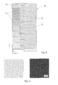
- Fig. 1 shows schematically the construction of an external drum exposure unit for exposure a printing original 15 on a recording material, in this example on a printing plate 3.
- An exposure drum 1 is rotatably mounted and can with a rotary drive not shown in the direction of the rotation arrow 2 in a uniform rotation can be offset.
- On the exposure drum 1 is an unexposed printing plate 3 by means of a terminal strip 9 at the front edge and fixed by means of clamping pieces 10 at the trailing edge.
- the printing plate 3 is flat by means of a vacuum device, not shown in Fig. 1, the pressure plate 3 sucks through holes in the drum surface, on the drum surface held, so that the pressure plate 3 is not affected by the centrifugal forces during rotation the exposure drum 1 is replaced.
- Multiple exposure heads 11 on a common exposure head carrier 16 are disposed at a relatively short distance axially on the exposure drum 1 while the exposure drum 1 is rotating.
- everyone Exposure head 11 focuses a bunch of exposure beams, in this example N laser beams 12, on the drum surface, the drum surface in the form of helical lines. This way, everyone will Drum rotation one or more groups of N recording lines in the circumferential direction x (main scanning direction) is exposed to the recording material.
- the exposure head carrier 16 is moved in the feeding direction y (sub-scanning direction) moved by means of a feed screw 13, with the erformschiüssig is connected and the offset with a feed drive 14 in rotary motion becomes.
- the feed drive 14 is a stepper motor, wherein the frequency of the The motor fed stepping motor clock the feed rate exactly can be adjusted.
- the productivity of the Exposure increases, especially for the exposure of large format printing plates 3, since a printing plate 3 can be exposed in a shorter time.
- two exposure heads 11 are present, in the feed direction are arranged at a distance W and in each case a bundle of N laser beams 12 focus on the pressure plate 3.
- the printing plate 3 is thereby simultaneously illuminated with two groups of recording lines, the axial distance W cover the drum surface.
- the imagesetter in the feed direction can record at three exposure heads 11 one third of this maximum length, etc.
- Fig. 2 illustrates the recording of the original 15, which is in the exposure each with N laser beams 12 results, on the unwound drum surface 20.
- the pressure plate 3 is clamped, on which the artwork 15 is recorded.
- the recording takes place in each case parallel with N laser beams 12, which are oriented as a feed direction linear Array of exposure points 21 are shown.
- the beam profile of a laser diode has the shape of a Gaussian bell curve, as shown in Fig. 3.
- the energy density H (r) has in the Center of the beam is a maximum value and decreases with increasing radius r a Gaussian function.
- thermal printing plate in which a polymer layer imagewise by the action of Laser energy is destroyed and eroded.
- a Such pressure plate is a positive pressure plate, as the non-color-leading Imaging be exposed imagewise.
- the term "positive” is out compared to the conventional copying of a positive color separation film derived on a printing plate, in which the printing plate through the transparent Film areas is exposed, i.e.. also on the non-color-leading Put.
- Fig. 4a shows schematically the position of the ink-conducting areas 25 of a positive pressure plate 3 relative to the exposed areas.
- FIG. 4 b shows the same relation for a negative pressure plate 3.
- a special test form is after the laser energy of the laser beams 12 first to a nominal operating point were set.
- a control device not explained here ensures that the N laser beams 12 within each exposure head 11 always emit the same laser energy once set.
- the N laser beams 12 as an array of exposure points 21, also as a laser module or module referred to.
- information such as "change in the Laser energy by ... mW "always on all laser beams 12 of a module, i.e. the Energy of all laser beams is changed by the same amount.
- the test form 50 becomes in the feed direction y over the entire width W of a recording tape 23 exposed.
- the extent of the test mold 50 in the circumferential direction x is arbitrary.
- the test form 50 includes a plurality of test fields 51 on a background surface 52. Background area 52 is rasterized with a constant tone, for example, with the tone value 70.0%. This tone value is particularly suitable good for the visual assessment of smallest density differences.
- One of the test fields 51 is rasterized with the same tone as the background area 52, the rest Test fields 51 are rasterized with tone values, which in small steps both down and up from the tonal value of the background area 52 differ, for example, in steps of 0.5%.
- test fields 51 The number of test fields 51 is obviously, for example, 21 test fields 51 in the tonal range of 65% can 75% are to be provided. In Fig. 5 are for clarity only seven test fields 51 shown.
- the test fields 51 are immediately at the left edge of the test form 50, i. in the circumferential direction x of the recording, arranged.
- the nominal ones Tonal values of the test fields 51 are next to the test fields 51 by Tonwertique 53, which is imprinted in the recording of the test form 50 become.
- Tonwertique 53 which is imprinted in the recording of the test form 50 become.
- module name 54 which indicates with which laser module the test form 50 was recorded has been.
- the different screened tonal values of the test fields 51 and the background area 52 are shown in Fig. 5 by differently dense hatching characterized.
- the test mold 50 becomes simultaneously with all the laser modules of the exposure heads 11 recorded.
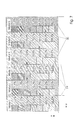
- Fig. 7 shows such a test exposure for an example in an imagesetter six exposure heads 11 are present and each other to be matched.
- the test exposure thus contains six in Feed direction y juxtaposed test forms 50, which at the recording tape boundaries 24 collide. Since the laser powers are still are not balanced, the test forms 50 from the laser modules with something recorded different area coverage, which in Fig. 7 again by different dense hatching is indicated. Despite the different Area coverage naturally has the test field 51 in all test forms 50 the nominal tonal value 70.0% the same area coverage as the background area 52 of the same test form 50.
- the visual comparison is more accurate than a density measurement, which would be subject to a measurement error of about 1% area coverage.
- density differences of ⁇ 0.5% are still perceptible.
- the test fields 51 exposed to the module 1 could also be omitted, since they are not compared to any adjacent background area 52, i.e. for the module 1 it would be sufficient to expose only the background area 52.
- the test mold 50 exposed to the module 2 has a slightly larger area coverage than the test form 50 exposed with the module 1, i.e. she is slightly darker overall. This is expressed in the fact that in the test form 50 of the module 2 the test field 51 with the nominal tone 69.5% already reaches the same area coverage as the background area 52 in FIG Test Form 50 of Module 1 with the nominal tone value 70.0%. For better Overview is this match in Fig. 7 marked with an arrow.
- the test form 50 of the module 3 is exposed overall somewhat brighter than the test form 50 of Module 2. Therefore, the area coverage of the background area becomes 52 of the module 2 of the module 3 first with the test field 51 with the nominal Tonal value 70.5% achieved.
- the visual comparison becomes at each recording band limit 24 between two modules, and the nominal ones Tone values of the test fields 51, their area coverage in each case with the area coverage the background of the previous module or the lowest Difference, be in the first line of an evaluation table entered.
- Fig. 8 shows the evaluation table for the test exposure of Fig. 7.
- a second line of the evaluation table will be the differences of the nominal Levels from line 1 to the respective predecessor module formed. These differences are then moved from module 1 to the current module added up, and the sum is in a third line of the evaluation table entered.
- the values in line 3 thus indicate which area coverage differences the recorded with the respective modules test forms 50 related to the test form written with Module 1. Based on these differences correction values could already be calculated by what amounts the laser powers of the individual modules must be increased or decreased, to match the exposure heads 11 to each other.
- the threshold M is undershot in which the polymer layer of the printing plate is secure and complete is removed (Fig.
- the inventive method was the example of a positive-working Pressure plate described. It can also work for negative pressure plates as well as for other recording materials, only to be noted is in which direction the laser powers have to be changed to For example, to effect a reduction of the area coverage, or which Thresholds or other limits must be met.
- the procedure and the test form 50 are also not for use in an external drum imagesetter limited, but they can with any design of a Druckvorlagebelichters be used, which is a print template with multiple exposure heads records.
Landscapes
- Physics & Mathematics (AREA)
- Engineering & Computer Science (AREA)
- Multimedia (AREA)
- Signal Processing (AREA)
- General Physics & Mathematics (AREA)
- Optics & Photonics (AREA)
- Exposure And Positioning Against Photoresist Photosensitive Materials (AREA)
- Manufacture Or Reproduction Of Printing Formes (AREA)
- Accessory Devices And Overall Control Thereof (AREA)
- Facsimile Heads (AREA)
Applications Claiming Priority (2)
| Application Number | Priority Date | Filing Date | Title |
|---|---|---|---|
| DE102004008074 | 2004-02-19 | ||
| DE102004008074A DE102004008074A1 (de) | 2004-02-19 | 2004-02-19 | Verfahren und Testform zum Abgleichen der Belichtungsköpfe in einem Belichter für Druckvorlagen |
Publications (3)
| Publication Number | Publication Date |
|---|---|
| EP1580980A2 true EP1580980A2 (fr) | 2005-09-28 |
| EP1580980A3 EP1580980A3 (fr) | 2010-01-20 |
| EP1580980B1 EP1580980B1 (fr) | 2011-12-28 |
Family
ID=34853522
Family Applications (1)
| Application Number | Title | Priority Date | Filing Date |
|---|---|---|---|
| EP05100371A Expired - Lifetime EP1580980B1 (fr) | 2004-02-19 | 2005-01-21 | Procédé et cliché pour égaliser les têtes d'exposition dans une unité d'exposition des données d'impression |
Country Status (5)
| Country | Link |
|---|---|
| US (1) | US7289137B2 (fr) |
| EP (1) | EP1580980B1 (fr) |
| JP (1) | JP4215730B2 (fr) |
| AT (1) | ATE539550T1 (fr) |
| DE (1) | DE102004008074A1 (fr) |
Families Citing this family (7)
| Publication number | Priority date | Publication date | Assignee | Title |
|---|---|---|---|---|
| JP4558464B2 (ja) * | 2004-11-30 | 2010-10-06 | 株式会社リコー | 画像形成装置及び画像形成方法 |
| US20070182808A1 (en) * | 2005-10-26 | 2007-08-09 | Lars Stiblert | Writing apparatuses and methods |
| US8122846B2 (en) * | 2005-10-26 | 2012-02-28 | Micronic Mydata AB | Platforms, apparatuses, systems and methods for processing and analyzing substrates |
| WO2014140047A2 (fr) | 2013-03-12 | 2014-09-18 | Micronic Mydata AB | Procédé et dispositif d'écriture de masques photographiques avec réduction des erreurs mura |
| KR102253995B1 (ko) | 2013-03-12 | 2021-05-18 | 마이크로닉 아베 | 기계적으로 생성된 정렬 표식 방법 및 정렬 시스템 |
| US10391786B2 (en) | 2015-10-30 | 2019-08-27 | Hewlett-Packard Development Company, L.P. | Print inconsistency quantification |
| WO2019037868A1 (fr) * | 2017-08-25 | 2019-02-28 | Hp Indigo B.V. | Ajustement de niveaux de puissance pour compenser une variation de taille de point d'impression |
Family Cites Families (16)
| Publication number | Priority date | Publication date | Assignee | Title |
|---|---|---|---|---|
| US5323179A (en) * | 1991-08-23 | 1994-06-21 | Eastman Kodak Company | Method of calibrating a multichannel printer |
| US5598272A (en) * | 1994-04-07 | 1997-01-28 | Imation, Inc. | Visual calibrator for color halftone imaging |
| US5638117A (en) | 1994-11-14 | 1997-06-10 | Sonnetech, Ltd. | Interactive method and system for color characterization and calibration of display device |
| US6034711A (en) * | 1996-03-06 | 2000-03-07 | Hewlett-Packard Company | Self-indicating test page for use in setting density level and color balance in a color laser printer |
| US5838117A (en) * | 1997-02-28 | 1998-11-17 | General Electric Company | Ballast circuit with synchronization and preheat functions |
| US6128090A (en) * | 1996-12-11 | 2000-10-03 | Agfa Gevaert N.V. | Visual control strip for imageable media |
| US6721061B1 (en) * | 1997-02-13 | 2004-04-13 | Agfa Corporation | Method and apparatus for display of banding |
| US5933578A (en) * | 1997-04-08 | 1999-08-03 | Barco Graphics, N.V. | Method and device for determining the color appearance of color overprints |
| JP4629226B2 (ja) | 1997-11-03 | 2011-02-09 | イーストマン コダック カンパニー | 複数の画像化出力装置を有する画像化装置を較正する方法及び装置 |
| US6268932B1 (en) * | 1998-04-23 | 2001-07-31 | Internatiaonal Business Machines Corporation | Gray scale calibration tool for setting the density of a printer |
| US6215562B1 (en) * | 1998-12-16 | 2001-04-10 | Electronics For Imaging, Inc. | Visual calibration |
| EP1199881A1 (fr) * | 2000-10-18 | 2002-04-24 | Ricoh Company, Ltd. | Appareil de formation d'image avec une régulation de la concentration de gris utilisant des motifs améliorés de référence et d'essai |
| US6832552B2 (en) * | 2001-06-26 | 2004-12-21 | Creo Inc. | Method of automated setting of imaging and processing parameters |
| US7034968B2 (en) * | 2001-08-31 | 2006-04-25 | Hewlett-Packard Development Company, L.P. | Color calibration chart |
| JP3820979B2 (ja) * | 2001-12-17 | 2006-09-13 | ブラザー工業株式会社 | パッチ形成装置およびプログラム |
| BR0307720A (pt) | 2002-02-14 | 2005-01-25 | Ranbaxi Lab Ltd | Formulações de atorvastatina estabilizadas com adições de metal alcalino, método para produzir uma formulação farmacêutica e estabilizar dita formulação |
-
2004
- 2004-02-19 DE DE102004008074A patent/DE102004008074A1/de not_active Withdrawn
-
2005
- 2005-01-21 AT AT05100371T patent/ATE539550T1/de active
- 2005-01-21 EP EP05100371A patent/EP1580980B1/fr not_active Expired - Lifetime
- 2005-02-21 JP JP2005044747A patent/JP4215730B2/ja not_active Expired - Fee Related
- 2005-02-22 US US11/062,998 patent/US7289137B2/en not_active Expired - Fee Related
Also Published As
| Publication number | Publication date |
|---|---|
| JP4215730B2 (ja) | 2009-01-28 |
| JP2005234586A (ja) | 2005-09-02 |
| US20050185161A1 (en) | 2005-08-25 |
| EP1580980A3 (fr) | 2010-01-20 |
| ATE539550T1 (de) | 2012-01-15 |
| DE102004008074A1 (de) | 2005-09-15 |
| US7289137B2 (en) | 2007-10-30 |
| EP1580980B1 (fr) | 2011-12-28 |
Similar Documents
| Publication | Publication Date | Title |
|---|---|---|
| DE2262824C3 (de) | Verfahren zur gerasterten Reproduktion farbiger Halbtonbilder im Ein- oder Mehrfarbendruck | |
| DE60119612T2 (de) | Mehrstrahlenbelichtungsgerät | |
| DE2809338C3 (de) | Schwärzungsdichte-Steuerungsanordnung für Tintenstrahldrucker | |
| DE69416029T2 (de) | Verfahren zur Korrektur von Halbtonpunktbilddaten und Bildverarbeitungsgerät das diese Korrektur verwendet | |
| DE10306104B4 (de) | Vorrichtung und Verfahren zur Erkennung der Kante eines Aufzeichnungsmaterials | |
| EP0074422A1 (fr) | Procédé pour la production de planches au moyen de points d'impression à distribution irrégulière | |
| DE2720782A1 (de) | Elektronischer halbton-generator | |
| EP0719434B1 (fr) | Systeme de generation d'une image matricielle sur un support d'enregistrement photosensible | |
| DE69608842T2 (de) | Grössenmodulierte stochastische Rasterung | |
| EP1580980B1 (fr) | Procédé et cliché pour égaliser les têtes d'exposition dans une unité d'exposition des données d'impression | |
| DE10353029B3 (de) | Vorrichtung und Verfahren zur Messung der Längenänderung der Vorschubspindel in einem Belichter für Druckvorlagen | |
| EP1450210B1 (fr) | Appareil et méthode pour détecter le bord d'un matériau d'enregistrement | |
| EP1530151B1 (fr) | Procédé pour corriger l'obliquité d'enregistrement lors de l'illumination d'une maquette d'impression | |
| DE2401672B2 (de) | Vorrichtung zur Kontrolle der Bildqualität eines in einem Reproduktions- und Druckverfahren zu verarbeitenden Bildes und Verfahren zur Herstellung der Vorrichtung | |
| EP1452311A2 (fr) | Arrangement pour tempérer un tambour d'exposition dans un appareil d'exposition pour plaques d'impression | |
| DE69326646T2 (de) | Verfahren und Vorrichtung zur Verbesserung von Auflösung und Kontrast durch eine überabgetastete Beleuchtung mit Intensitätssteuerung in einem zwei-dimensionalen mikro- adressierbaren Drucker | |
| DE69714197T2 (de) | Sichtbarer Kontrollstreifen für Abbildungsmedien | |
| EP1454743B1 (fr) | Dispositif de mise au point d'une tête d'exposition dans un dispositif d'exposition de plaques | |
| WO1991013511A1 (fr) | Procede et dispositif de fabrication d'un original reproductible | |
| DE2219442A1 (de) | Bildübertragungsgerät, insbesondere Faksimileschreiber | |
| DE3421914C2 (de) | Einrichtung zum Korrigieren einer Abweichung der Lumineszenz von lichtemittierenden Punkten eines Lichtdruckkopfes und Verfahren zu deren Herstellung | |
| EP2177356B1 (fr) | Compensation d'erreurs dans un système d'imagerie | |
| DE3010880C2 (de) | Rasterumsetzungsverfahren zum Gravieren von Druckformen | |
| DE3046397C2 (de) | Digitale Fotosetzmaschine | |
| EP0029561A1 (fr) | Procédé et dispositif pour déterminer des valeurs de réglage prescrites, en particulier pour le préréglage automatique de machines à imprimer |
Legal Events
| Date | Code | Title | Description |
|---|---|---|---|
| PUAI | Public reference made under article 153(3) epc to a published international application that has entered the european phase |
Free format text: ORIGINAL CODE: 0009012 |
|
| AK | Designated contracting states |
Kind code of ref document: A2 Designated state(s): AT BE BG CH CY CZ DE DK EE ES FI FR GB GR HU IE IS IT LI LT LU MC NL PL PT RO SE SI SK TR |
|
| AX | Request for extension of the european patent |
Extension state: AL BA HR LV MK YU |
|
| PUAL | Search report despatched |
Free format text: ORIGINAL CODE: 0009013 |
|
| AK | Designated contracting states |
Kind code of ref document: A3 Designated state(s): AT BE BG CH CY CZ DE DK EE ES FI FR GB GR HU IE IS IT LI LT LU MC NL PL PT RO SE SI SK TR |
|
| AX | Request for extension of the european patent |
Extension state: AL BA HR LV MK YU |
|
| RIC1 | Information provided on ipc code assigned before grant |
Ipc: H04N 1/407 20060101ALI20091214BHEP Ipc: H04N 1/401 20060101AFI20050729BHEP |
|
| 17P | Request for examination filed |
Effective date: 20100720 |
|
| 17Q | First examination report despatched |
Effective date: 20100813 |
|
| AKX | Designation fees paid |
Designated state(s): AT BE BG CH CY CZ DE DK EE ES FI FR GB GR HU IE IS IT LI LT LU MC NL PL PT RO SE SI SK TR |
|
| GRAP | Despatch of communication of intention to grant a patent |
Free format text: ORIGINAL CODE: EPIDOSNIGR1 |
|
| RTI1 | Title (correction) |
Free format text: METHOD AND PRINTING PLATE FOR ADJUSTING EXPOSURE HEADS IN AN EXPOSURE UNIT FOR PRINT DATA |
|
| RIN1 | Information on inventor provided before grant (corrected) |
Inventor name: LIEBIG, NORBERTC/O HEIDELBERGER DRUCKMASCHINEN |
|
| GRAS | Grant fee paid |
Free format text: ORIGINAL CODE: EPIDOSNIGR3 |
|
| GRAA | (expected) grant |
Free format text: ORIGINAL CODE: 0009210 |
|
| AK | Designated contracting states |
Kind code of ref document: B1 Designated state(s): AT BE BG CH CY CZ DE DK EE ES FI FR GB GR HU IE IS IT LI LT LU MC NL PL PT RO SE SI SK TR |
|
| REG | Reference to a national code |
Ref country code: GB Ref legal event code: FG4D Free format text: NOT ENGLISH |
|
| REG | Reference to a national code |
Ref country code: CH Ref legal event code: EP |
|
| REG | Reference to a national code |
Ref country code: AT Ref legal event code: REF Ref document number: 539550 Country of ref document: AT Kind code of ref document: T Effective date: 20120115 |
|
| REG | Reference to a national code |
Ref country code: IE Ref legal event code: FG4D |
|
| REG | Reference to a national code |
Ref country code: NL Ref legal event code: T3 |
|
| REG | Reference to a national code |
Ref country code: DE Ref legal event code: R096 Ref document number: 502005012265 Country of ref document: DE Effective date: 20120322 |
|
| PG25 | Lapsed in a contracting state [announced via postgrant information from national office to epo] |
Ref country code: LT Free format text: LAPSE BECAUSE OF FAILURE TO SUBMIT A TRANSLATION OF THE DESCRIPTION OR TO PAY THE FEE WITHIN THE PRESCRIBED TIME-LIMIT Effective date: 20111228 |
|
| LTIE | Lt: invalidation of european patent or patent extension |
Effective date: 20111228 |
|
| PG25 | Lapsed in a contracting state [announced via postgrant information from national office to epo] |
Ref country code: GR Free format text: LAPSE BECAUSE OF FAILURE TO SUBMIT A TRANSLATION OF THE DESCRIPTION OR TO PAY THE FEE WITHIN THE PRESCRIBED TIME-LIMIT Effective date: 20120329 Ref country code: SI Free format text: LAPSE BECAUSE OF FAILURE TO SUBMIT A TRANSLATION OF THE DESCRIPTION OR TO PAY THE FEE WITHIN THE PRESCRIBED TIME-LIMIT Effective date: 20111228 Ref country code: SE Free format text: LAPSE BECAUSE OF FAILURE TO SUBMIT A TRANSLATION OF THE DESCRIPTION OR TO PAY THE FEE WITHIN THE PRESCRIBED TIME-LIMIT Effective date: 20111228 |
|
| PG25 | Lapsed in a contracting state [announced via postgrant information from national office to epo] |
Ref country code: CY Free format text: LAPSE BECAUSE OF FAILURE TO SUBMIT A TRANSLATION OF THE DESCRIPTION OR TO PAY THE FEE WITHIN THE PRESCRIBED TIME-LIMIT Effective date: 20111228 |
|
| REG | Reference to a national code |
Ref country code: IE Ref legal event code: FD4D |
|
| BERE | Be: lapsed |
Owner name: HEIDELBERGER DRUCKMASCHINEN A.G. Effective date: 20120131 |
|
| PG25 | Lapsed in a contracting state [announced via postgrant information from national office to epo] |
Ref country code: EE Free format text: LAPSE BECAUSE OF FAILURE TO SUBMIT A TRANSLATION OF THE DESCRIPTION OR TO PAY THE FEE WITHIN THE PRESCRIBED TIME-LIMIT Effective date: 20111228 Ref country code: IE Free format text: LAPSE BECAUSE OF FAILURE TO SUBMIT A TRANSLATION OF THE DESCRIPTION OR TO PAY THE FEE WITHIN THE PRESCRIBED TIME-LIMIT Effective date: 20111228 Ref country code: IS Free format text: LAPSE BECAUSE OF FAILURE TO SUBMIT A TRANSLATION OF THE DESCRIPTION OR TO PAY THE FEE WITHIN THE PRESCRIBED TIME-LIMIT Effective date: 20120428 Ref country code: SK Free format text: LAPSE BECAUSE OF FAILURE TO SUBMIT A TRANSLATION OF THE DESCRIPTION OR TO PAY THE FEE WITHIN THE PRESCRIBED TIME-LIMIT Effective date: 20111228 Ref country code: BG Free format text: LAPSE BECAUSE OF FAILURE TO SUBMIT A TRANSLATION OF THE DESCRIPTION OR TO PAY THE FEE WITHIN THE PRESCRIBED TIME-LIMIT Effective date: 20120328 Ref country code: CZ Free format text: LAPSE BECAUSE OF FAILURE TO SUBMIT A TRANSLATION OF THE DESCRIPTION OR TO PAY THE FEE WITHIN THE PRESCRIBED TIME-LIMIT Effective date: 20111228 |
|
| PG25 | Lapsed in a contracting state [announced via postgrant information from national office to epo] |
Ref country code: RO Free format text: LAPSE BECAUSE OF FAILURE TO SUBMIT A TRANSLATION OF THE DESCRIPTION OR TO PAY THE FEE WITHIN THE PRESCRIBED TIME-LIMIT Effective date: 20111228 Ref country code: PT Free format text: LAPSE BECAUSE OF FAILURE TO SUBMIT A TRANSLATION OF THE DESCRIPTION OR TO PAY THE FEE WITHIN THE PRESCRIBED TIME-LIMIT Effective date: 20120430 Ref country code: MC Free format text: LAPSE BECAUSE OF NON-PAYMENT OF DUE FEES Effective date: 20120131 Ref country code: PL Free format text: LAPSE BECAUSE OF FAILURE TO SUBMIT A TRANSLATION OF THE DESCRIPTION OR TO PAY THE FEE WITHIN THE PRESCRIBED TIME-LIMIT Effective date: 20111228 |
|
| REG | Reference to a national code |
Ref country code: CH Ref legal event code: PL |
|
| PGFP | Annual fee paid to national office [announced via postgrant information from national office to epo] |
Ref country code: IT Payment date: 20120127 Year of fee payment: 8 |
|
| PG25 | Lapsed in a contracting state [announced via postgrant information from national office to epo] |
Ref country code: DK Free format text: LAPSE BECAUSE OF FAILURE TO SUBMIT A TRANSLATION OF THE DESCRIPTION OR TO PAY THE FEE WITHIN THE PRESCRIBED TIME-LIMIT Effective date: 20111228 Ref country code: LI Free format text: LAPSE BECAUSE OF NON-PAYMENT OF DUE FEES Effective date: 20120131 Ref country code: CH Free format text: LAPSE BECAUSE OF NON-PAYMENT OF DUE FEES Effective date: 20120131 |
|
| PLBE | No opposition filed within time limit |
Free format text: ORIGINAL CODE: 0009261 |
|
| STAA | Information on the status of an ep patent application or granted ep patent |
Free format text: STATUS: NO OPPOSITION FILED WITHIN TIME LIMIT |
|
| 26N | No opposition filed |
Effective date: 20121001 |
|
| PG25 | Lapsed in a contracting state [announced via postgrant information from national office to epo] |
Ref country code: BE Free format text: LAPSE BECAUSE OF NON-PAYMENT OF DUE FEES Effective date: 20120131 |
|
| REG | Reference to a national code |
Ref country code: DE Ref legal event code: R097 Ref document number: 502005012265 Country of ref document: DE Effective date: 20121001 |
|
| REG | Reference to a national code |
Ref country code: AT Ref legal event code: MM01 Ref document number: 539550 Country of ref document: AT Kind code of ref document: T Effective date: 20120121 |
|
| PG25 | Lapsed in a contracting state [announced via postgrant information from national office to epo] |
Ref country code: ES Free format text: LAPSE BECAUSE OF FAILURE TO SUBMIT A TRANSLATION OF THE DESCRIPTION OR TO PAY THE FEE WITHIN THE PRESCRIBED TIME-LIMIT Effective date: 20120408 |
|
| PGFP | Annual fee paid to national office [announced via postgrant information from national office to epo] |
Ref country code: NL Payment date: 20130121 Year of fee payment: 9 |
|
| PG25 | Lapsed in a contracting state [announced via postgrant information from national office to epo] |
Ref country code: FI Free format text: LAPSE BECAUSE OF FAILURE TO SUBMIT A TRANSLATION OF THE DESCRIPTION OR TO PAY THE FEE WITHIN THE PRESCRIBED TIME-LIMIT Effective date: 20111228 Ref country code: AT Free format text: LAPSE BECAUSE OF NON-PAYMENT OF DUE FEES Effective date: 20120121 |
|
| PG25 | Lapsed in a contracting state [announced via postgrant information from national office to epo] |
Ref country code: TR Free format text: LAPSE BECAUSE OF FAILURE TO SUBMIT A TRANSLATION OF THE DESCRIPTION OR TO PAY THE FEE WITHIN THE PRESCRIBED TIME-LIMIT Effective date: 20111228 |
|
| PG25 | Lapsed in a contracting state [announced via postgrant information from national office to epo] |
Ref country code: LU Free format text: LAPSE BECAUSE OF NON-PAYMENT OF DUE FEES Effective date: 20120121 |
|
| PG25 | Lapsed in a contracting state [announced via postgrant information from national office to epo] |
Ref country code: HU Free format text: LAPSE BECAUSE OF FAILURE TO SUBMIT A TRANSLATION OF THE DESCRIPTION OR TO PAY THE FEE WITHIN THE PRESCRIBED TIME-LIMIT Effective date: 20050121 |
|
| REG | Reference to a national code |
Ref country code: NL Ref legal event code: V1 Effective date: 20140801 |
|
| PG25 | Lapsed in a contracting state [announced via postgrant information from national office to epo] |
Ref country code: NL Free format text: LAPSE BECAUSE OF NON-PAYMENT OF DUE FEES Effective date: 20140801 |
|
| REG | Reference to a national code |
Ref country code: FR Ref legal event code: PLFP Year of fee payment: 11 |
|
| PGFP | Annual fee paid to national office [announced via postgrant information from national office to epo] |
Ref country code: DE Payment date: 20150131 Year of fee payment: 11 |
|
| PGFP | Annual fee paid to national office [announced via postgrant information from national office to epo] |
Ref country code: FR Payment date: 20150119 Year of fee payment: 11 Ref country code: GB Payment date: 20150122 Year of fee payment: 11 |
|
| PG25 | Lapsed in a contracting state [announced via postgrant information from national office to epo] |
Ref country code: IT Free format text: LAPSE BECAUSE OF NON-PAYMENT OF DUE FEES Effective date: 20140121 |
|
| REG | Reference to a national code |
Ref country code: DE Ref legal event code: R119 Ref document number: 502005012265 Country of ref document: DE |
|
| GBPC | Gb: european patent ceased through non-payment of renewal fee |
Effective date: 20160121 |
|
| REG | Reference to a national code |
Ref country code: FR Ref legal event code: ST Effective date: 20160930 |
|
| PG25 | Lapsed in a contracting state [announced via postgrant information from national office to epo] |
Ref country code: GB Free format text: LAPSE BECAUSE OF NON-PAYMENT OF DUE FEES Effective date: 20160121 Ref country code: DE Free format text: LAPSE BECAUSE OF NON-PAYMENT OF DUE FEES Effective date: 20160802 |
|
| PG25 | Lapsed in a contracting state [announced via postgrant information from national office to epo] |
Ref country code: FR Free format text: LAPSE BECAUSE OF NON-PAYMENT OF DUE FEES Effective date: 20160201 |