EP1580856A1 - Hochspannungsschaltanlage in Freiluftbauweise - Google Patents
Hochspannungsschaltanlage in Freiluftbauweise Download PDFInfo
- Publication number
- EP1580856A1 EP1580856A1 EP04405185A EP04405185A EP1580856A1 EP 1580856 A1 EP1580856 A1 EP 1580856A1 EP 04405185 A EP04405185 A EP 04405185A EP 04405185 A EP04405185 A EP 04405185A EP 1580856 A1 EP1580856 A1 EP 1580856A1
- Authority
- EP
- European Patent Office
- Prior art keywords
- module
- encapsulated
- circuit breaker
- circuit
- dds
- Prior art date
- Legal status (The legal status is an assumption and is not a legal conclusion. Google has not performed a legal analysis and makes no representation as to the accuracy of the status listed.)
- Granted
Links
- 238000010276 construction Methods 0.000 claims abstract description 13
- 238000000926 separation method Methods 0.000 claims description 7
- 239000008186 active pharmaceutical agent Substances 0.000 abstract description 12
- 238000009434 installation Methods 0.000 abstract description 5
- 238000002955 isolation Methods 0.000 abstract description 2
- 238000006880 cross-coupling reaction Methods 0.000 description 12
- 238000010586 diagram Methods 0.000 description 7
- 239000007789 gas Substances 0.000 description 4
- 238000005538 encapsulation Methods 0.000 description 3
- 238000005516 engineering process Methods 0.000 description 3
- IJGRMHOSHXDMSA-UHFFFAOYSA-N Atomic nitrogen Chemical compound N#N IJGRMHOSHXDMSA-UHFFFAOYSA-N 0.000 description 2
- 229910018503 SF6 Inorganic materials 0.000 description 2
- 238000006243 chemical reaction Methods 0.000 description 2
- 230000002950 deficient Effects 0.000 description 2
- 238000006073 displacement reaction Methods 0.000 description 2
- 238000010615 ring circuit Methods 0.000 description 2
- SFZCNBIFKDRMGX-UHFFFAOYSA-N sulfur hexafluoride Chemical compound FS(F)(F)(F)(F)F SFZCNBIFKDRMGX-UHFFFAOYSA-N 0.000 description 2
- 239000003570 air Substances 0.000 description 1
- 239000004020 conductor Substances 0.000 description 1
- 230000009977 dual effect Effects 0.000 description 1
- 239000000203 mixture Substances 0.000 description 1
- 229910052757 nitrogen Inorganic materials 0.000 description 1
- 230000001681 protective effect Effects 0.000 description 1
- 238000005086 pumping Methods 0.000 description 1
- 229960000909 sulfur hexafluoride Drugs 0.000 description 1
Images


Classifications
-
- H—ELECTRICITY
- H02—GENERATION; CONVERSION OR DISTRIBUTION OF ELECTRIC POWER
- H02B—BOARDS, SUBSTATIONS OR SWITCHING ARRANGEMENTS FOR THE SUPPLY OR DISTRIBUTION OF ELECTRIC POWER
- H02B5/00—Non-enclosed substations; Substations with enclosed and non-enclosed equipment
- H02B5/06—Non-enclosed substations; Substations with enclosed and non-enclosed equipment gas-insulated
Definitions
- the invention is based on a high-voltage switchgear
- This switchgear has at least one busbar designed in open-air construction and at least two with the Busbar connectable cubicles.
- In one of the buttons is a Encapsulated gas-insulated circuit arrangement provided in modular design, the at least one as a disconnector and at least one as a circuit breaker executed module contains.
- Such often referred to as a hybrid system switchgear has a switch panels span spanning scaffold on which in general a Busbar system in Freiluftbauweise and branches, such as feeds and consumer outlets are supported. At least one of the cubicles generally contains a single or multi-phase encapsulated, gas-isolated Circuit arrangement in modular design, which depending on the configuration one more or less highly available connection between the busbar system and the branches or between two of the busbars of the Busbar system guaranteed.
- the modules of the encapsulated circuit arrangement are filled with an insulating gas, for example nitrogen, air, sulfur hexafluoride (SF 6 ) alone or in mixture, up to a few bar pressure and are typically loaded with high voltages of more than 100 kV during operation of the system.
- Typical modules are designed as power, as a disconnector, as grounding, as a combined disconnector and earthing switch, as a current and / or voltage measuring device or as a current or voltage limiter.
- the switchgear of the type mentioned above is opposite Switchgear exclusively designed in open-air technology because of the encapsulated trained circuitry through high availability over a long period of time and due to a small footprint.
- the invention takes a prior art of Switchgear reference, as in DE 29 29 054 A1, DE 100 11 888 A1 or US 2004/0027791 A1 is described.
- Those from this state of the art Prior art switchgear each have a busbar system, which at least one busbar designed in Freiluftbauweise included, as well as branch panels, each with a gas-insulated Branch circuit and are provided with an outgoing led to outdoor.
- the Gas-insulated circuit arrangements are according to conventional technology executed one or three-phase encapsulated, therefore, these arrangements have in relation to correspondingly configured circuit arrangements in Outdoor construction high availability.
- the switchgear according to the invention is between a separation and a Circuit breaker module of the encapsulated circuit arrangement a Querdemontage enabling at least one of the two switch modules Assembly module arranged. Therefore, a heavily loaded component of encapsulated circuit arrangement, namely the separation or the Circuit breaker module without changing the position of the other component must be removed by transverse removal from the plant. After replacing the removed component can so within a few hours the full Availability of the system can be restored quickly and cost effectively. Long Downtime - as with conventionally designed gas-insulated ones Circuit arrangements - are avoided. Because of that individual Components selectively from the typically associated with a branch Circuitry can be expanded, therefore, in general neither another branch of the affected panel nor one the whole Plant concerned Busbar be switched off. By suitable arranged grounding devices can easily all safety distances be respected. When replacing the component to be replaced additional protective measures dispensable.
- the switchgear according to the invention at least two in Freiluftbauweise executed busbars on and a running as a cross coupling encapsulated circuit arrangement in which a first breaker module with a first of the two busbars and one with the circuit breaker module connected second circuit breaker module with the second busbar is connected, so it is recommended between the second separation and Circuit-breaker module a transverse disassembly of the circuit breaker to arrange enabling second mounting module.
- two Mounting modules can cross-section of the circuit breaker module without any Displacement perpendicular to the direction of dismantling done.
- a selective expansion of this Circuit breaker module in the comparatively complicated constructed 11 ⁇ 2-circuit arrangement is guaranteed then.
- the selectivity and thus the Availability will be increased if the second arm of the first T Disconnector module via a third mounting module with the second of the three Circuit breaker modules and the second arm of the T of the second Disconnector module via a fourth mounting module with the third Circuit breaker module is connected, or if in addition a fifth and a sixth mounting module and one with the first of both busbars connected third and connected to the second bus fourth Disconnector module are provided, and if the fifth mounting module between the second power switch module and the third Isolator module and the sixth mounting module between the third Circuit breaker module and the fourth circuit breaker module are arranged.
- switchgear with at least two outdoor busbars and with at least two mutually differing panels arranged and each containing at least one branch circuit arrangements should the circuit arrangements different circuit configurations and at least one of the circuit configurations should be encapsulated and be executed gas-insulated. Thanks to the space-saving training of encapsulated, gas-insulated circuitry can be so existing Outdoor facilities are easily converted and existing branches by differently formed and / or arranged circuit arrangements to the Busbars are connected, which depending on the requirement a ensure particularly high or only a low level of availability.
- the encapsulated circuit arrangement in Double busbar or 11 ⁇ 2-switch configuration executed. If may also be provided a further encapsulated circuit arrangement be.
- the first of these two encapsulated circuit arrangements can then in 11 ⁇ 2-switch configuration and the second in dual busbar configuration or in a different from the first encapsulated circuit arrangement Construction of the 11 ⁇ 2-switch configuration, especially in longitudinal or U-construction, be executed.
- a ring configuration be provided.
- This ring configuration should conveniently be encapsulated be executed and included in the encapsulated circuitry.
- the switchgear recommends it itself to perform the encapsulated circuit arrangement in ring-cross design.
- the encapsulated circuitry additionally contain a double busbar branch. A switch under load is then possible in this branch, if the assigned Connection switch in the ring configuration is closed.
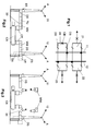
- FIGS. 1 to 3 designate like-acting parts.
- the illustrated in Figures 1 to 3 embodiment of the switchgear according to the invention has the apparent from Figure 1 circuit diagram and includes two trained in Freiluftbauweise and guided in Figures 2 and 3 perpendicular to the image plane busbars 11 and 12 and four panels, of which three are each formed as a branch field 21, 22 and 23 and one is a cross-coupling field 20. All panels have an encapsulated and gas-insulated designed circuit arrangement, which is connected between the two bus bars 11 and 12. A circuit arrangement contained in the cross-coupling field 20 and designated by the reference numeral 30 is shown in FIGS. 2 and 3.
- the circuit arrangement 30 is seen to be modular and includes a designed as a circuit breaker encapsulation module CB, two each designed as a circuit breaker encapsulation modules DS and two mounting modules MM , each between one of the circuit breaker modules DS and the circuit breaker module CB are arranged and ensure the electrical connection between the two power terminals of the circuit breaker CB and the two disconnectors DS.
- the same arrangement is also achieved for the intermediate switch located in the middle in a 11 ⁇ 2-switch configuration.
- Such a 11 ⁇ 2-switch configuration will be shown later in FIGS. 4 and 5.
- the switch CB corresponding intermediate switch is designated there CB 1 .
- the disconnecting switches DS are each routed via an unspecified outdoor bushing to one of the two busbars 11 and 12, respectively, and to two outgoing circuits A 1 in the case of the 11 ⁇ 2-switch configuration according to FIGS. 4 and 5.
- a tubular connection module TU is additionally arranged, which compensates for the predetermined by the isolation distances in air large geometric dimensions of the panel 20.
- the circuit arrangement includes additional modules CT, ES, VT and SA, which in turn perform the functions of current conversion, grounding, voltage conversion and overvoltage limiting.
- the mounting modules MM correspond to the well-known from the technology of gas-insulated switchgear and forth in the publication no. CH-HS 1215 87 D "SF6 gas insulated switchgear (GIS) type ELK" the company BBC Brown Boveri AG Hochhardstechnik, CH- 5401 Baden Switzerland, 15 described ELK VQ cross-disassembly elements, which are installed in gas-insulated switchgear between individual sections of the busbar, long rail connections as well as transformer and cable connections and allow axial removal of the encapsulation and the conductor tube, the expansion of system parts, without disassembling adjacent sections ,
- GIS gas insulated switchgear
- the mounting module MM has a sealed and filled with insulating gas space.
- the two mounting modules MM are brought to ground potential with open disconnectors DS and closed earthing switches ES.
- the mounting modules MM can now be moved axially after pumping the insulating gas and removed from the system.
- the defective component CB can then be removed by transverse displacement from the plant and replaced by a new component, without changing the position of the other components.
- the transverse disassembly can already be performed with a single mounting module.
- the switchgear according to FIGS. 4 and 5 has two busbars 11 and 12 designed in an open-air design, as well as two cubicles 24 and 25, each of which has an encapsulated circuit arrangement in 11 ⁇ 2-switch configuration with three circuit breaker modules CB 1 , CB 2 and CB 3 and two branches A included.
- One of these two encapsulated circuit arrangements is shown schematically in FIG.
- This arrangement includes two circuit breaker modules DDS 1 and DDS 2 , which are each connected via a mounting modules MM , each having one of both terminals of a provided in the center of the assembly circuit breaker CB 1 .
- the two circuit breaker modules DDS 1 and DDS 2 are each designed in the manner of a T.
- the two arms of the T each have a disconnecting switch point.
- the leg of the T contains a node connected to one of the two branches A.
- the power switch module CB 1 arranged in the middle is connected via a first mounting module MM to the left-hand arm of the T of the disconnect switch module DDS 1 and via a second mounting module MM to the right-hand arm of the disconnector module DDS 2 .
- the rightward arm of the T of the disconnector module DDS 1 is connected to the circuit breaker module CB 2 via a third mounting module MM
- the left arm T of the second circuit breaker module DDS 2 is connected to the circuit breaker module CB 3 via a fourth mounting module MM .
- a fifth and a sixth mounting module MM and a busbar 12 connected to the disconnect switch module DS 1 and connected to the busbar 11 fourth circuit breaker module DS 2 are provided and the fifth mounting module between the circuit breaker module CB 2 and the disconnect switch module DS 1 and the sixth mounting modules between the circuit breaker module CB 3 and the circuit breaker module DS 2 arranged.
- the fifth mounting module between the circuit breaker module CB 2 and the disconnect switch module DS 1 and the sixth mounting modules between the circuit breaker module CB 3 and the circuit breaker module DS 2 arranged.
- six mounting modules MM are required, especially if an axial disassembly is possible.
- the switchgear according to FIGS. 6 and 7 has two open-air designs executed busbars 11 and 12 and eight panels 20 to 27 on with each of an encapsulated circuit arrangement.
- the encapsulated Circuit arrangements of the panels 21, 22 and 23 are each in Double busbar configuration formed, d. H. instruct one with one Branch A and connected to a circuit breaker module DDS in T-construction Circuit-breaker CB on, each containing a separation point Arms of the T are each connected to one of the two busbars 11 and 12 respectively and the leg of the T is connected to the power switch module CB.
- the Panels 24 to 27 each contain a 11 ⁇ 2-switch configuration encapsulated circuit arrangements, which in the panels 24 and 25 Longitudinal and in the panels 26 and 27 have U-type.
- the encapsulated circuitry of the panel 20 is as a cross-coupling educated. Such a cross coupling is not necessarily required in principle, because the function of the cross coupling through the 11 ⁇ 2-switch configuration of Branches 24 to
- this switchgear is differently configured encapsulated Contains circuit arrangements, the switchgear for the different circuit arrangements associated branch fields different availabilities, for the panels 24 to 27 a higher Availability as for the panels 21 to 23. Compared to a system after the State of the art, in which the branches formed identically encapsulated Have circuit arrangements, so under assurance optimal selective Availability of the switchgear significantly cheaper manufactured and maintained become.
- the three switchgear according to the figures 8 to 10 have instead of a busbar designed in Freiluftbauweise an encapsulated executed ring configuration 13 without explicit busbar, which is integrated into the encapsulated circuitry and alternately in the ring circuit breaker modules CB and DDS switch modules.
- the circuit breaker modules DDS are designed in T-construction, wherein the foot of the T contains a junction following the branch A. Between adjacent and mutually electrically connected modules, a mounting module MM is arranged in each case (shown in FIGS. 8 and 10 only when the circuit breaker module CB is positioned at the top).
- the encapsulated circuit is executed in ring-cross design. It also has a further circuit breaker module CB ', which is connected via two mounting modules MM with two diagonally opposite in the ring circuit breaker modules DDS' and DDS "in cross-construction with three separation points and a branch A subsequent node.
- Fig. 10 is an embodiment of the switchgear according to the invention represented, which has an encapsulated executed ring configuration 13 at a double busbar branch A 'for an undesignated feed, For example, a transformer attached.
- the two attack Trennerschaltmodule DS of the branch circuit, which normally at the Double busbar are connected to the disconnector switch modules DDS the ring configuration 13 too. Switching under load is possible if the here acting as a clutch switch connection switch CB the Ring configuration 13 is closed.
Landscapes
- Engineering & Computer Science (AREA)
- Power Engineering (AREA)
- Gas-Insulated Switchgears (AREA)
Abstract
Description
- Fig. 1
- ein einpolig dargestelltes Schaltschema einer dreiphasigen Hochspannungsschaltanlage nach der Erfindung mit einer Doppelsammelschiene in Freiluftbauweise sowie mit drei Abzweigfeldern und einem Querkupplungsfeld, jeweils enthaltend eine gekapselte, gasisolierte Schaltungsanordnung in Modulbauweise,
- Fig. 2
- eine auf einen Pol des Querkupplungsfeldes geführte Ansicht der Schaltanlage gemäss Fig.1,
- Fig. 3
- eine Ansicht des Querkupplungsfeldes gemäss Fig.2 beim Ausbau einer Komponente der gekapselten Schaltungsanordnung,
- Fig.4
- ein einpolig dargestelltes Schaltschema einer dreiphasigen Ausführungsform der Schaltanlage nach der Erfindung mit einer Doppelsammelschiene in Freiluftbauweise sowie mit zwei Schaltfeldem, bei denen die gekapselte Schaltungsanordnung jeweils in 1½-Schalterkonfiguration ausgeführt ist,
- Fig.5
- eine schematische Darstellung der in der gekapselten Schaltungsanordnung der Anlage gemäss Fig.4 enthaltenen Module,
- Fig.6
- ein einpolig dargestelltes Schaltschema einer dreiphasigen Ausführungsform der Schaltanlage nach der Erfindung mit einer Doppelsammelschiene in Freiluftbauweise sowie mit einem Querkupplungsfeld, drei Abzweigfelder in Doppelsammelschienenbauweise und vier Abzweigfelder in 1½-Schalterkonfiguration,
- Fig.7
- eine Aufsicht auf ein dreipolig dargestelltes Layout der Schaltanlage nach Fig.6,
- Fig.8
- ein einpolig dargestelltes Schaltschema einer dreiphasigen Ausführungsform der Schaltanlage nach der Erfindung in Ringbauweise,
- Fig.9
- ein einpolig dargestelltes Schaltschema einer dreiphasigen Ausführungsform der Schaltanlage nach der Erfindung mit einer Doppelsammelschiene in Ring-Kreuzbauweise, und
- Fig. 10
- ein einpolig dargestelltes Schaltschema einer dreiphasigen Ausführungsform der Schaltanlage nach der Erfindung in Ringbauweise mit angehängtem Doppelsammelschienenabzweig.
- 11, 12
- Sammelschienen
- 13
- Ringsammelschiene
- 20
- Schaltfeld für Querkupplung
- 21 bis 27,
- Schaltfelder für Abzweige
- 30
- gekapselte Schaltungsanordnung
- CB, CB1, CB2, CB3
- Leistungsschaltermodule
- DS, DS1, DS2,
- Trennschaltermodule
- DDS, DDS1, DDS2, DDS', DDS" MM
- Montagemodul
- A, A'
- Abzweige
- ES
- Erdermodul
- CT
- Stromwandlermodul
- VT
- Spannungswandlermodul
- SA
- Überspannungsableitermodul
Claims (11)
- Hochspannungsschaltanlage mit
mindestens einer in Freiluftbauweise ausgeführten Sammelschiene (11, 12), mindestens zwei mit der Sammelschiene verbindbaren Schaltfeldern (20, 21 bis 27), und
mindestens einer in einem der Schaltfelder angeordneten gekapselten, gasisolierten Schaltungsanordung (30) in Modulbauweise, enthaltend mindestens ein erstes Trennschaltermodul (DS, DS1, DS2, DDS, DDS1, DDS2, DDS', DDS") und mindestens ein erstes Leistungsschaltermodul (CB, CB', CB1, CB2, CB3),
dadurch gekennzeichnet, dass zwischen dem ersten Trenn- und dem ersten Leistungsschaltermodul ein eine Querdemontage mindestens eines der beiden Schaltermodule ermöglichendes erstes Montagemodul (MM) angeordnet ist. - Hochspannungsschaltanlage nach Anspruch 1 mit mindestens zwei in Freiluftbauweise ausgeführten Sammelschienen (11, 12) und mit einer als Querkupplung ausgeführten gekapselten Schaltungsanordnung (30), bei der das erste Trennschaltermodul (DS) mit einer ersten (11) der beiden Sammelschienen und ein mit dem ersten Leistungsschaltermodul (CB) verbundenes zweites Trennschaltermodul (DS) mit der zweiten Sammelschiene (12) verbunden ist, dadurch gekennzeichnet, dass zwischen dem zweiten Trenn- und dem ersten Leistungsschaltermodul ein eine Querdemontage des Leistungsschalters ermöglichendes zweites Montagemodul (MM) angeordnet ist.
- Hochspannungsschaltanlage nach Anspruch 1 mit mindestens zwei in Freiluftbauweise ausgeführten Sammelschienen (11, 12) und mit einer in 1½-Schalterkonfiguration ausgeführten gekapselten Schaltungsanordnung mit drei Leistungsschaltermodulen (CB1, CB2, CB3) und zwei Abzweigen (A), bei der das erste und ein zweites Trennschaltermodul (DDS1, DDS2) nach Art eines T ausgebildet sind, dessen beide Arme jeweils eine Trennschaltstelle aufweisen und dessen Bein einen mit einem der beiden Abzweige (A) verbindbaren Knotenpunkt enthält,
dadurch gekennzeichnet, dass das erste Leistungsschaltermodul (CB1, CB2, CB3) über das erste Montagemodul (MM) mit einem ersten Arm des T des ersten Trennschaltermoduls (DDS1) und über ein zweites Montagemodul (MM) mit dem ersten Arm des T des zweiten Trennschaltermoduls (DDS2) verbunden ist. - Hochspannungsschaltanlage nach Anspruch 3, dadurch gekennzeichnet, dass der zweite Arm des T des ersten Trennschaltermoduls (DDS1) über ein drittes Montagemodul (MM) mit dem zweiten (CB2) der drei Leistungsschaltermodule (CB1, CB2, CB3) und der zweite Arm des T des zweiten Trennschaltermoduls (DDS2) über ein viertes Montagemodul (MM) mit dem dritten Leistungsschaltermodul (CB3) verbunden ist.
- Hochspannungsschaltanlage nach Anspruch 4, dadurch gekennzeichnet, dass zusätzlich ein fünftes und ein sechstes Montagemodul (MM) sowie ein mit der ersten (12) der beiden Sammelschienen verbundenes drittes (DS1) und ein mit der zweiten Sammelschiene (11) verbundenes viertes Trennschaltermodul (DS2) vorgesehen sind, und dass das fünfte Montagemodul (MM) zwischen dem zweiten Leistungsschaltermodul (CB2) und dem dritten Trennschaltermodul (DS1) und das sechste Montagemodule (MM) zwischen dem dritten Leistungsschaltermodul (CB3) und dem vierten Trennschaltermodul (DS2) angeordnet sind.
- Hochspannungsschaltanlage, insbesondere nach einem der Ansprüche 1 bis 5, mit mindestens zwei in Freiluftbauweise ausgeführten Sammelschienen (11, 12) und mit mindestens zwei in voneinander abweichenden Schaltfeldern (21 bis 27) angeordneten und jeweils mindestens einen Abzweig (A) enthaltenden Schaltungsanordnungen, dadurch gekennzeichnet, dass die Schaltungsanordnungen unterschiedliche Schaltungskonfigurationen aufweisen, und dass mindestens eine erste der Schaltungskonfigurationen gekapselt und gasisoliert ausgeführt ist.
- Hochspannungsschaltanlage nach Anspruch 6, dadurch gekennzeichnet, dass die erste gekapselte Schaltungsanordnung in Doppelsammelschienen- oder 1½-Schalterkonfiguration ausgeführt ist.
- Hochspannungsschaltanlage nach Anspruch 7, dadurch gekennzeichnet, dass eine zweite gekapselte Schaltungsanordnung vorgesehen ist, dass die erste gekapselte Schaltungsanordnung in 1½-Schalterkonfiguration und die zweite gekapselte Schaltungsanordnung in Doppelsammelschienenkonfiguration oder in einer von der ersten gekapselten Schaltungsanordnung abweichenden Bauweise der 1½-Schalterkonfiguration, insbesondere in Längs- oder in U-Bauweise, ausgeführt ist.
- Hochspannungsschaltanlage nach Anspruch 1, bei der anstelle einer Sammelschiene eine Ringkonfiguration (13) vorgesehen ist, dadurch gekennzeichnet, dass die Ringkonfiguration (13) gekapselt ausgeführt und in der gekapselten Schaltungsanordnung enthalten ist.
- Hochspannungsschaltanlage nach Anspruch 9, dadurch gekennzeichnet, dass die gekapselte Schaltungsanordnung in Ring-Kreuzbauweise ausgeführt ist.
- Hochspannungsschaltanlage nach einem der Ansprüche 9 oder 10, dadurch gekennzeichnet, dass die gekapselte Schaltungsanordnung zusätzlich einen Doppelsammelschienenabzweig (A') aufweist.
Priority Applications (6)
| Application Number | Priority Date | Filing Date | Title |
|---|---|---|---|
| EP04405185A EP1580856B1 (de) | 2004-03-25 | 2004-03-25 | Hochspannungsschaltanlage in Freiluftbauweise |
| US11/076,888 US7310220B2 (en) | 2004-03-25 | 2005-03-11 | High voltage outdoor substation |
| AU2005201095A AU2005201095B2 (en) | 2004-03-25 | 2005-03-11 | High-voltage outdoor substation |
| BR0501289-9A BRPI0501289A (pt) | 2004-03-25 | 2005-03-24 | Subestação de alta tensão ao tempo |
| CN200510056974.2A CN1674376B (zh) | 2004-03-25 | 2005-03-24 | 高压户外变电站 |
| RU2005108409/09A RU2345460C2 (ru) | 2004-03-25 | 2005-03-24 | Высоковольтное распределительное устройство открытой конструкции |
Applications Claiming Priority (1)
| Application Number | Priority Date | Filing Date | Title |
|---|---|---|---|
| EP04405185A EP1580856B1 (de) | 2004-03-25 | 2004-03-25 | Hochspannungsschaltanlage in Freiluftbauweise |
Publications (2)
| Publication Number | Publication Date |
|---|---|
| EP1580856A1 true EP1580856A1 (de) | 2005-09-28 |
| EP1580856B1 EP1580856B1 (de) | 2012-06-20 |
Family
ID=34854744
Family Applications (1)
| Application Number | Title | Priority Date | Filing Date |
|---|---|---|---|
| EP04405185A Expired - Lifetime EP1580856B1 (de) | 2004-03-25 | 2004-03-25 | Hochspannungsschaltanlage in Freiluftbauweise |
Country Status (6)
| Country | Link |
|---|---|
| US (1) | US7310220B2 (de) |
| EP (1) | EP1580856B1 (de) |
| CN (1) | CN1674376B (de) |
| AU (1) | AU2005201095B2 (de) |
| BR (1) | BRPI0501289A (de) |
| RU (1) | RU2345460C2 (de) |
Cited By (1)
| Publication number | Priority date | Publication date | Assignee | Title |
|---|---|---|---|---|
| CN109066320A (zh) * | 2018-08-28 | 2018-12-21 | 江苏科能电力工程咨询有限公司 | 应用于双母线出线的hgis设备 |
Families Citing this family (9)
| Publication number | Priority date | Publication date | Assignee | Title |
|---|---|---|---|---|
| DE112009002045T5 (de) * | 2009-06-12 | 2011-07-28 | Abb Technology Ag | Dielektrisches Isolationsmedium |
| CN101980407A (zh) * | 2010-10-15 | 2011-02-23 | 卧龙电气集团股份有限公司 | 快装式变电站 |
| DK2652752T3 (en) * | 2010-12-14 | 2016-01-11 | Abb Technology Ag | Dielectric INSULATION MEDIUM |
| CA2840383A1 (en) * | 2014-01-21 | 2015-07-21 | Abb Inc. | Site replacement of internal saturable reactors of a rectifier power transformer |
| NL2015357B1 (en) * | 2015-08-27 | 2017-03-20 | Univ Delft Tech | DC switch yard and method to operate such a DC switch yard. |
| CN106253124A (zh) * | 2016-08-31 | 2016-12-21 | 中国电力技术装备有限公司郑州电力设计院 | 750kV变电站创新一字型GIS布置结构 |
| IT201900018818A1 (it) * | 2019-10-15 | 2021-04-15 | Terna S P A | Linea di trasmissione elettrica aerea ad alta tensione equipaggiata con unità di manovra |
| RU2744255C1 (ru) * | 2020-04-03 | 2021-03-04 | Федеральное государственное бюджетное образовательное учреждение высшего образования "Кубанский государственный аграрный университет имени И.Т. Трубилина" | Открытое распределительное устройство электрической станции с шестью блоками генератор-трансформатор, семью линиями и автотрансформатором связи |
| CN116547878B (zh) * | 2020-12-23 | 2025-11-07 | Abb瑞士股份有限公司 | 用于测量开关设备的温度的装置和开关设备 |
Citations (4)
| Publication number | Priority date | Publication date | Assignee | Title |
|---|---|---|---|---|
| DE19904402A1 (de) * | 1998-08-27 | 2000-06-21 | Abb Patent Gmbh | Hochspannungsschaltanlage und Verfahren zum Transport der Hochspannungsschaltanlage |
| EP1168551A1 (de) * | 2000-06-23 | 2002-01-02 | Alstom | Hybrid-Hochspannungsstation mit metallgekapselter Sammelschienenanordnung und luftisolierter Notstromversorgung |
| US20040027791A1 (en) * | 2000-10-20 | 2004-02-12 | Jean Marmonier | High voltage hybrid station with opposite busbars and shielded cutoff and switching modules for same |
| US20040037025A1 (en) * | 2002-08-06 | 2004-02-26 | Mitsubishi Denki Kabushiki Kaisha | Hybrid gas-insulated switchgear |
Family Cites Families (6)
| Publication number | Priority date | Publication date | Assignee | Title |
|---|---|---|---|---|
| JPS6223203Y2 (de) | 1978-07-19 | 1987-06-13 | ||
| FR2448799A1 (fr) * | 1979-02-07 | 1980-09-05 | Alsthom Cgee | Poste electrique a tres haute tension |
| DE4419380C1 (de) * | 1994-05-30 | 1995-10-19 | Siemens Ag | Leistungsschaltermodul |
| EP1110285B1 (de) * | 1998-08-27 | 2010-01-13 | Abb Ag | Hochspannungsschaltanlage und verfahren zum transport der hochspannungsschaltanlage |
| DE10011888C2 (de) | 2000-03-07 | 2002-02-07 | Siemens Ag | Dreiphasige Hochspannungsschaltanlage mit einphasig gekapselten Baugruppen |
| US6233137B1 (en) * | 2000-05-25 | 2001-05-15 | Mathias Kolos | Compact power distribution substation |
-
2004
- 2004-03-25 EP EP04405185A patent/EP1580856B1/de not_active Expired - Lifetime
-
2005
- 2005-03-11 US US11/076,888 patent/US7310220B2/en not_active Expired - Fee Related
- 2005-03-11 AU AU2005201095A patent/AU2005201095B2/en not_active Ceased
- 2005-03-24 BR BR0501289-9A patent/BRPI0501289A/pt not_active Application Discontinuation
- 2005-03-24 CN CN200510056974.2A patent/CN1674376B/zh not_active Expired - Fee Related
- 2005-03-24 RU RU2005108409/09A patent/RU2345460C2/ru not_active IP Right Cessation
Patent Citations (4)
| Publication number | Priority date | Publication date | Assignee | Title |
|---|---|---|---|---|
| DE19904402A1 (de) * | 1998-08-27 | 2000-06-21 | Abb Patent Gmbh | Hochspannungsschaltanlage und Verfahren zum Transport der Hochspannungsschaltanlage |
| EP1168551A1 (de) * | 2000-06-23 | 2002-01-02 | Alstom | Hybrid-Hochspannungsstation mit metallgekapselter Sammelschienenanordnung und luftisolierter Notstromversorgung |
| US20040027791A1 (en) * | 2000-10-20 | 2004-02-12 | Jean Marmonier | High voltage hybrid station with opposite busbars and shielded cutoff and switching modules for same |
| US20040037025A1 (en) * | 2002-08-06 | 2004-02-26 | Mitsubishi Denki Kabushiki Kaisha | Hybrid gas-insulated switchgear |
Cited By (2)
| Publication number | Priority date | Publication date | Assignee | Title |
|---|---|---|---|---|
| CN109066320A (zh) * | 2018-08-28 | 2018-12-21 | 江苏科能电力工程咨询有限公司 | 应用于双母线出线的hgis设备 |
| CN109066320B (zh) * | 2018-08-28 | 2023-12-12 | 江苏科能电力工程咨询有限公司 | 应用于双母线出线的hgis设备 |
Also Published As
| Publication number | Publication date |
|---|---|
| US20050213288A1 (en) | 2005-09-29 |
| RU2005108409A (ru) | 2006-09-10 |
| CN1674376B (zh) | 2010-09-08 |
| AU2005201095B2 (en) | 2009-10-29 |
| US7310220B2 (en) | 2007-12-18 |
| CN1674376A (zh) | 2005-09-28 |
| BRPI0501289A (pt) | 2005-11-08 |
| AU2005201095A1 (en) | 2005-10-13 |
| EP1580856B1 (de) | 2012-06-20 |
| RU2345460C2 (ru) | 2009-01-27 |
Similar Documents
| Publication | Publication Date | Title |
|---|---|---|
| EP1719225B1 (de) | Gekapselte gasisolierte schaltanlage | |
| DE2754691C2 (de) | Ein- oder mehrphasig metallgekapselte, druckgasisolierte Hochspannungsschaltanlage | |
| EP2151027B1 (de) | Hochspannungsschaltanlage | |
| DE3715053A1 (de) | Metallgekapselte, mit druckgas gefuellte, mehrphasige hochspannungsschaltanlage | |
| DE3915948A1 (de) | Lastschaltanlage mit einem dreistellungsschalter | |
| DE102007045486B4 (de) | Modulare Schaltanlage zur Energieverteilung | |
| EP1580856B1 (de) | Hochspannungsschaltanlage in Freiluftbauweise | |
| DE3885155T2 (de) | Gasisolierte Schaltanlage. | |
| EP1060548A1 (de) | Metallgekapselte, gasiolierte schaltanlagen mit gasgefüllten behältern | |
| DE19805705A1 (de) | Gasisolierte metallgekapselte Schaltanlage | |
| EP2104969B1 (de) | Hochspannungsschaltanlage | |
| DE68904362T2 (de) | Gekapselte station fuer hochspannung mit zweifachversorgung. | |
| EP0796502B1 (de) | Metallgekapselte schaltanlage mit einem vakuumschaltgerät | |
| EP0099970B1 (de) | Schaltanlage | |
| DE68920899T2 (de) | Zelle für gekapselte Mittel oder Hochspannungsstation und Station, die aus solchen Zellen aufgebaut ist. | |
| WO2002015352A1 (de) | Gasisolierte schaltanlage mit dreiphasigem sammelschienensystem | |
| EP0075967B1 (de) | Schaltanlage | |
| DE202006008709U1 (de) | Anschlussschaltfeld für Mittelspannungsschaltanlagen | |
| DE2720325A1 (de) | Metallgekapselte, druckgasisolierte hochspannungsschaltanlage | |
| DE102017203894A1 (de) | Schalteranordnung und luftisolierte Schaltanlage | |
| DE10013232A1 (de) | Mehrphasig gekapselte, gasiolierte Hochspannungsschalteinrichtung in Freiluftausführung | |
| DE19744464C1 (de) | Mittelspannungsschaltanlage für im Ringnetz angeordnete Umspannstationen | |
| WO2003063314A2 (de) | Gasisolierte hochspannungsschaltanlage | |
| EP0989650A1 (de) | Hochspannungssammelschiene mit Abgängen in Freiluftisolationsabständen | |
| DE202006005093U1 (de) | Schaltvorrichtung für ein Mittelspannungsnetz |
Legal Events
| Date | Code | Title | Description |
|---|---|---|---|
| PUAI | Public reference made under article 153(3) epc to a published international application that has entered the european phase |
Free format text: ORIGINAL CODE: 0009012 |
|
| AK | Designated contracting states |
Kind code of ref document: A1 Designated state(s): AT BE BG CH CY CZ DE DK EE ES FI FR GB GR HU IE IT LI LU MC NL PL PT RO SE SI SK TR |
|
| AX | Request for extension of the european patent |
Extension state: AL LT LV MK |
|
| 17P | Request for examination filed |
Effective date: 20060211 |
|
| AKX | Designation fees paid |
Designated state(s): AT BE BG CH CY CZ DE DK EE ES FI FR GB GR HU IE IT LI LU MC NL PL PT RO SE SI SK TR |
|
| GRAP | Despatch of communication of intention to grant a patent |
Free format text: ORIGINAL CODE: EPIDOSNIGR1 |
|
| GRAS | Grant fee paid |
Free format text: ORIGINAL CODE: EPIDOSNIGR3 |
|
| GRAJ | Information related to disapproval of communication of intention to grant by the applicant or resumption of examination proceedings by the epo deleted |
Free format text: ORIGINAL CODE: EPIDOSDIGR1 |
|
| 17Q | First examination report despatched |
Effective date: 20110419 |
|
| GRAP | Despatch of communication of intention to grant a patent |
Free format text: ORIGINAL CODE: EPIDOSNIGR1 |
|
| GRAS | Grant fee paid |
Free format text: ORIGINAL CODE: EPIDOSNIGR3 |
|
| GRAA | (expected) grant |
Free format text: ORIGINAL CODE: 0009210 |
|
| AK | Designated contracting states |
Kind code of ref document: B1 Designated state(s): AT BE BG CH CY CZ DE DK EE ES FI FR GB GR HU IE IT LI LU MC NL PL PT RO SE SI SK TR |
|
| REG | Reference to a national code |
Ref country code: GB Ref legal event code: FG4D Free format text: NOT ENGLISH |
|
| REG | Reference to a national code |
Ref country code: CH Ref legal event code: EP |
|
| REG | Reference to a national code |
Ref country code: AT Ref legal event code: REF Ref document number: 563507 Country of ref document: AT Kind code of ref document: T Effective date: 20120715 |
|
| REG | Reference to a national code |
Ref country code: IE Ref legal event code: FG4D Free format text: LANGUAGE OF EP DOCUMENT: GERMAN |
|
| REG | Reference to a national code |
Ref country code: DE Ref legal event code: R096 Ref document number: 502004013594 Country of ref document: DE Effective date: 20120823 |
|
| REG | Reference to a national code |
Ref country code: CH Ref legal event code: NV Representative=s name: ABB SCHWEIZ AG INTELLECTUAL PROPERTY (CH-LC/IP) |
|
| PG25 | Lapsed in a contracting state [announced via postgrant information from national office to epo] |
Ref country code: SE Free format text: LAPSE BECAUSE OF FAILURE TO SUBMIT A TRANSLATION OF THE DESCRIPTION OR TO PAY THE FEE WITHIN THE PRESCRIBED TIME-LIMIT Effective date: 20120620 Ref country code: FI Free format text: LAPSE BECAUSE OF FAILURE TO SUBMIT A TRANSLATION OF THE DESCRIPTION OR TO PAY THE FEE WITHIN THE PRESCRIBED TIME-LIMIT Effective date: 20120620 |
|
| REG | Reference to a national code |
Ref country code: NL Ref legal event code: VDEP Effective date: 20120620 |
|
| PG25 | Lapsed in a contracting state [announced via postgrant information from national office to epo] |
Ref country code: SI Free format text: LAPSE BECAUSE OF FAILURE TO SUBMIT A TRANSLATION OF THE DESCRIPTION OR TO PAY THE FEE WITHIN THE PRESCRIBED TIME-LIMIT Effective date: 20120620 Ref country code: GR Free format text: LAPSE BECAUSE OF FAILURE TO SUBMIT A TRANSLATION OF THE DESCRIPTION OR TO PAY THE FEE WITHIN THE PRESCRIBED TIME-LIMIT Effective date: 20120921 |
|
| PG25 | Lapsed in a contracting state [announced via postgrant information from national office to epo] |
Ref country code: RO Free format text: LAPSE BECAUSE OF FAILURE TO SUBMIT A TRANSLATION OF THE DESCRIPTION OR TO PAY THE FEE WITHIN THE PRESCRIBED TIME-LIMIT Effective date: 20120620 Ref country code: CY Free format text: LAPSE BECAUSE OF FAILURE TO SUBMIT A TRANSLATION OF THE DESCRIPTION OR TO PAY THE FEE WITHIN THE PRESCRIBED TIME-LIMIT Effective date: 20120620 Ref country code: SK Free format text: LAPSE BECAUSE OF FAILURE TO SUBMIT A TRANSLATION OF THE DESCRIPTION OR TO PAY THE FEE WITHIN THE PRESCRIBED TIME-LIMIT Effective date: 20120620 Ref country code: CZ Free format text: LAPSE BECAUSE OF FAILURE TO SUBMIT A TRANSLATION OF THE DESCRIPTION OR TO PAY THE FEE WITHIN THE PRESCRIBED TIME-LIMIT Effective date: 20120620 Ref country code: EE Free format text: LAPSE BECAUSE OF FAILURE TO SUBMIT A TRANSLATION OF THE DESCRIPTION OR TO PAY THE FEE WITHIN THE PRESCRIBED TIME-LIMIT Effective date: 20120620 |
|
| PG25 | Lapsed in a contracting state [announced via postgrant information from national office to epo] |
Ref country code: PL Free format text: LAPSE BECAUSE OF FAILURE TO SUBMIT A TRANSLATION OF THE DESCRIPTION OR TO PAY THE FEE WITHIN THE PRESCRIBED TIME-LIMIT Effective date: 20120620 Ref country code: PT Free format text: LAPSE BECAUSE OF FAILURE TO SUBMIT A TRANSLATION OF THE DESCRIPTION OR TO PAY THE FEE WITHIN THE PRESCRIBED TIME-LIMIT Effective date: 20121022 |
|
| PG25 | Lapsed in a contracting state [announced via postgrant information from national office to epo] |
Ref country code: NL Free format text: LAPSE BECAUSE OF FAILURE TO SUBMIT A TRANSLATION OF THE DESCRIPTION OR TO PAY THE FEE WITHIN THE PRESCRIBED TIME-LIMIT Effective date: 20120620 |
|
| PLBE | No opposition filed within time limit |
Free format text: ORIGINAL CODE: 0009261 |
|
| STAA | Information on the status of an ep patent application or granted ep patent |
Free format text: STATUS: NO OPPOSITION FILED WITHIN TIME LIMIT |
|
| PG25 | Lapsed in a contracting state [announced via postgrant information from national office to epo] |
Ref country code: DK Free format text: LAPSE BECAUSE OF FAILURE TO SUBMIT A TRANSLATION OF THE DESCRIPTION OR TO PAY THE FEE WITHIN THE PRESCRIBED TIME-LIMIT Effective date: 20120620 Ref country code: ES Free format text: LAPSE BECAUSE OF FAILURE TO SUBMIT A TRANSLATION OF THE DESCRIPTION OR TO PAY THE FEE WITHIN THE PRESCRIBED TIME-LIMIT Effective date: 20121001 |
|
| PGFP | Annual fee paid to national office [announced via postgrant information from national office to epo] |
Ref country code: DE Payment date: 20130321 Year of fee payment: 10 Ref country code: CH Payment date: 20130322 Year of fee payment: 10 Ref country code: GB Payment date: 20130321 Year of fee payment: 10 Ref country code: FR Payment date: 20130408 Year of fee payment: 10 |
|
| 26N | No opposition filed |
Effective date: 20130321 |
|
| PGFP | Annual fee paid to national office [announced via postgrant information from national office to epo] |
Ref country code: AT Payment date: 20130313 Year of fee payment: 10 |
|
| REG | Reference to a national code |
Ref country code: DE Ref legal event code: R097 Ref document number: 502004013594 Country of ref document: DE Effective date: 20130321 |
|
| PG25 | Lapsed in a contracting state [announced via postgrant information from national office to epo] |
Ref country code: BG Free format text: LAPSE BECAUSE OF FAILURE TO SUBMIT A TRANSLATION OF THE DESCRIPTION OR TO PAY THE FEE WITHIN THE PRESCRIBED TIME-LIMIT Effective date: 20120920 |
|
| BERE | Be: lapsed |
Owner name: ABB TECHNOLOGY A.G. Effective date: 20130331 |
|
| REG | Reference to a national code |
Ref country code: HU Ref legal event code: AG4A Ref document number: E016977 Country of ref document: HU |
|
| PG25 | Lapsed in a contracting state [announced via postgrant information from national office to epo] |
Ref country code: MC Free format text: LAPSE BECAUSE OF NON-PAYMENT OF DUE FEES Effective date: 20130331 |
|
| PGFP | Annual fee paid to national office [announced via postgrant information from national office to epo] |
Ref country code: HU Payment date: 20130319 Year of fee payment: 10 |
|
| REG | Reference to a national code |
Ref country code: IE Ref legal event code: MM4A |
|
| PG25 | Lapsed in a contracting state [announced via postgrant information from national office to epo] |
Ref country code: IE Free format text: LAPSE BECAUSE OF NON-PAYMENT OF DUE FEES Effective date: 20130325 Ref country code: BE Free format text: LAPSE BECAUSE OF NON-PAYMENT OF DUE FEES Effective date: 20130331 |
|
| REG | Reference to a national code |
Ref country code: DE Ref legal event code: R119 Ref document number: 502004013594 Country of ref document: DE |
|
| REG | Reference to a national code |
Ref country code: CH Ref legal event code: PL |
|
| REG | Reference to a national code |
Ref country code: AT Ref legal event code: MM01 Ref document number: 563507 Country of ref document: AT Kind code of ref document: T Effective date: 20140325 |
|
| GBPC | Gb: european patent ceased through non-payment of renewal fee |
Effective date: 20140325 |
|
| REG | Reference to a national code |
Ref country code: FR Ref legal event code: ST Effective date: 20141128 |
|
| REG | Reference to a national code |
Ref country code: DE Ref legal event code: R119 Ref document number: 502004013594 Country of ref document: DE Effective date: 20141001 |
|
| PG25 | Lapsed in a contracting state [announced via postgrant information from national office to epo] |
Ref country code: FR Free format text: LAPSE BECAUSE OF NON-PAYMENT OF DUE FEES Effective date: 20140331 Ref country code: LI Free format text: LAPSE BECAUSE OF NON-PAYMENT OF DUE FEES Effective date: 20140331 Ref country code: GB Free format text: LAPSE BECAUSE OF NON-PAYMENT OF DUE FEES Effective date: 20140325 Ref country code: DE Free format text: LAPSE BECAUSE OF NON-PAYMENT OF DUE FEES Effective date: 20141001 Ref country code: CH Free format text: LAPSE BECAUSE OF NON-PAYMENT OF DUE FEES Effective date: 20140331 |
|
| PG25 | Lapsed in a contracting state [announced via postgrant information from national office to epo] |
Ref country code: AT Free format text: LAPSE BECAUSE OF NON-PAYMENT OF DUE FEES Effective date: 20140325 Ref country code: HU Free format text: LAPSE BECAUSE OF NON-PAYMENT OF DUE FEES Effective date: 20140326 |
|
| PG25 | Lapsed in a contracting state [announced via postgrant information from national office to epo] |
Ref country code: IT Free format text: LAPSE BECAUSE OF NON-PAYMENT OF DUE FEES Effective date: 20140325 |
|
| PG25 | Lapsed in a contracting state [announced via postgrant information from national office to epo] |
Ref country code: TR Free format text: LAPSE BECAUSE OF FAILURE TO SUBMIT A TRANSLATION OF THE DESCRIPTION OR TO PAY THE FEE WITHIN THE PRESCRIBED TIME-LIMIT Effective date: 20120620 |
|
| PG25 | Lapsed in a contracting state [announced via postgrant information from national office to epo] |
Ref country code: LU Free format text: LAPSE BECAUSE OF NON-PAYMENT OF DUE FEES Effective date: 20130325 |