EP1580765B1 - Collimateur secondaire pour dispositif à rayons X diffusés et dispositif à rayons X diffusés - Google Patents
Collimateur secondaire pour dispositif à rayons X diffusés et dispositif à rayons X diffusés Download PDFInfo
- Publication number
- EP1580765B1 EP1580765B1 EP05006638A EP05006638A EP1580765B1 EP 1580765 B1 EP1580765 B1 EP 1580765B1 EP 05006638 A EP05006638 A EP 05006638A EP 05006638 A EP05006638 A EP 05006638A EP 1580765 B1 EP1580765 B1 EP 1580765B1
- Authority
- EP
- European Patent Office
- Prior art keywords
- collimator
- secondary collimator
- ray
- detector
- ray source
- Prior art date
- Legal status (The legal status is an assumption and is not a legal conclusion. Google has not performed a legal analysis and makes no representation as to the accuracy of the status listed.)
- Ceased
Links
Images
Classifications
-
- G—PHYSICS
- G01—MEASURING; TESTING
- G01N—INVESTIGATING OR ANALYSING MATERIALS BY DETERMINING THEIR CHEMICAL OR PHYSICAL PROPERTIES
- G01N23/00—Investigating or analysing materials by the use of wave or particle radiation, e.g. X-rays or neutrons, not covered by groups G01N3/00 – G01N17/00, G01N21/00 or G01N22/00
- G01N23/02—Investigating or analysing materials by the use of wave or particle radiation, e.g. X-rays or neutrons, not covered by groups G01N3/00 – G01N17/00, G01N21/00 or G01N22/00 by transmitting the radiation through the material
- G01N23/04—Investigating or analysing materials by the use of wave or particle radiation, e.g. X-rays or neutrons, not covered by groups G01N3/00 – G01N17/00, G01N21/00 or G01N22/00 by transmitting the radiation through the material and forming images of the material
-
- G—PHYSICS
- G21—NUCLEAR PHYSICS; NUCLEAR ENGINEERING
- G21K—TECHNIQUES FOR HANDLING PARTICLES OR IONISING RADIATION NOT OTHERWISE PROVIDED FOR; IRRADIATION DEVICES; GAMMA RAY OR X-RAY MICROSCOPES
- G21K1/00—Arrangements for handling particles or ionising radiation, e.g. focusing or moderating
- G21K1/02—Arrangements for handling particles or ionising radiation, e.g. focusing or moderating using diaphragms, collimators
- G21K1/025—Arrangements for handling particles or ionising radiation, e.g. focusing or moderating using diaphragms, collimators using multiple collimators, e.g. Bucky screens; other devices for eliminating undesired or dispersed radiation
Definitions
- the invention relates to a secondary collimator for an X-ray diffraction device and to an X-ray diffraction device for checking luggage.
- X-ray scattering devices According to the US 5,394,453 known.
- a baggage check is performed by means of a fan beam.
- the fan beam is obtained by a primary slit collimator which passes only a narrow beam of primary radiation from an electron beam radiation source.
- a piece of luggage to be examined is hit by the fan beam.
- the radiation scattered by a region of the item of luggage to be examined is imaged onto a detector field via a secondary collimator.
- the detector thus "sees" through the secondary collimator a certain spatially defined area of the item of luggage to be examined (tomography).
- a secondary collimator for an X-ray diffraction device which has horizontal slats and vertical slats arranged perpendicular thereto.
- the vertical slats are arranged parallel to one another and inclined by a predefinable scattering angle to a transmission direction of an X-ray beam.
- the horizontal slats are fan-shaped aligned with the X-ray source.
- the horizontal and vertical slats together form a rectangular grid and are combined in a collimator unit.
- US 4,057,726 discloses a collimator of bent lead sheet quarrels.
- the object of the invention is therefore to obtain a stable and stiff scatter collimator, which leads to a highly precise XRD profile of the area to be checked in the item of luggage to be checked in the detector.
- a secondary collimator according to the invention having the features of patent claim 1.
- a number of metal sheets are arranged on a sturdy, rigid base plate, having the folded surfaces, each adjacent surfaces are perpendicular to each other and the first metal sheet is firmly connected to the base plate and the second metal sheet is firmly connected to the first metal sheet and the next metal sheet is firmly connected to the previous.
- a horizontal lamella is understood to be a lamella which runs perpendicular to the XZ plane.
- a vertical lamella is therefore understood to mean a lamella which runs perpendicular to the YZ plane.
- the two terms “horizontal” and “vertical” are arbitrary, since the XZ plane is not necessarily vertical and the YZ plane is not necessarily horizontal. This depends inter alia on the installation of the X-ray scattering device.
- the lamellae are made of an X-ray absorbing material, in particular made of steel, and have a thickness of less than 1 mm, in particular about 100 ⁇ m. This ensures that only the scattered radiation from the area to be examined of the item of luggage to be examined strikes the detector to which the respective detector element is coded.
- the rectangular grid at the far end of the X-ray source has a width of 1-10 mm in the direction of the vertical slats and a height of 0.5-2.5 mm per grid element in the direction of the horizontal slats. It is thereby achieved that each grating element of the secondary collimator corresponds at its detector-side end to an element of the detector field of size and thus an unambiguous assignment of the stray radiation passing through the respective grating element is given.
- the collimator unit has a width of a total of 350 mm at its x-ray source-far end in the direction of the vertical slats and at the same time at its x-ray source-near end in the direction of the vertical slats a total width of 228 mm and the x-ray source has a total height of 250 mm and an opening angle of 12 °.
- a module is created which can be used exactly five times in a normal fan beam with an opening angle of 60 °.
- a complete coverage of the entire opening angle of the fan beam is possible or just a partial area.
- a further advantageous embodiment provides that the collimator unit is arranged in a vertical steel container. This makes it possible, when two or more collimator units are arranged as modules next to each other, to achieve a very precise alignment with each other.
- a further advantageous embodiment provides that five collimator units are joined together, which have a total opening angle of 60 °. As a result, the entire opening angle range of the fan beam of the X-ray source is covered and pivoting of the scattering collimator in conjunction with the detector does not have to be carried out in order to be able to check the item of luggage to be examined in one pass.
- a further advantageous embodiment provides that a total of 18 metal sheets are arranged on the base plate.
- a Kolllimatoraku is created, which extends over the entire length of the detector array.
- a further advantageous embodiment provides that at the opposite end of the base plate, the metal sheet is firmly connected to a robust, rigid cover plate. By using a cover plate an even higher rigidity of the collimator unit is achieved.
- An advantageous development of the X-ray scattering device provides that in addition a transmission detector in a straight extension from the X-ray source is arranged over the area of the item of luggage to be examined. As a result, it is possible for shielded regions to be detected in the item of luggage to be examined, for a correction of the attenuation effects with respect to scatter data to be performed, and for a pre-scan fluoroscopic image of the item of luggage to be examined to be obtained.
- a further advantageous development of the X-ray scattering device provides that the secondary collimator is aligned in the vertical direction parallel to the fan beam and is aligned in the horizontal direction on the area of the item of luggage to be examined. This makes it possible to inspect the item of luggage to be examined without any pivoting or axial movement of the secondary collimator and the detector field when the piece of luggage to be examined is moved via a conveyor belt between the primary collimator and the secondary collimator.
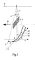
- Fig. 1 is a perspective view of a schematically illustrated X-ray scattering device reproduced, but in particular a primary collimator and a secondary collimator 1 have been omitted for clarity.
- An X-ray source O generates a fan beam 2 by means of a primary collimator (not shown).
- the slot-shaped primary collimator is made of a material that strongly absorbs X-rays, such as copper or a lead compound.
- an electron-beam radiation source in the high-power region for example, 15 kW
- medium-voltage for example, 180 kV
- the primary collimator used is a slit collimator which passes only a thin fan beam 2 onto the item of luggage 3 to be examined.
- Both the X-ray source O and the Primmaschinekollimator are known in principle and not essential to the invention, so that will not be discussed in more detail on their detailed design.
- the fan beam 2 transmitted through the primary collimator has an aperture angle ⁇ of 60 ° and a thickness in the Y direction of approximately 1 mm.
- the scattering point P is shown.
- the X-ray source O and the Scattering point P defines the Z-axis.
- the X-ray radiation transmitted along the Z-axis impinges on a detector 4 at the transmission point D.
- This transmission point D defines the origin of the Cartesian coordinate system X, Y, Z.
- the X-axis is defined so that it extends parallel to the plane in which the opening angle ⁇ of the fan beam 2 extends.
- On the perpendicular to the X-axis and Z-axis extending Y-axis hits a scattered beam to another detector element 40 of the detector 4.
- the coding of the scattering point P in the baggage item 3 to the specified scattered beam point D 'via the geometry of the Sekundärkollimators 1, what down to the FIGS. 2 and 3 is described.
- the detector 4 used is a room temperature semiconductor such as CdZnTe.
- the detector 4 is designed as a two-dimensional segmented detector array. For clarity, only two rows of detector elements 40 are shown.
- a first detector row 41 extends through the transmission point D in the XZ plane.
- a second detector row 42 of detector elements 40 passes through the scattered beam point D '.
- the first detector row 41 extends in the X direction from the starting point A to the end point B of the detector 4. These two points are determined by the opening angle ⁇ of the fan beam 2.
- the area of the scatter detector 4 is segmented in steps of about 1.5 mm in the Y direction and about 2 mm in the X direction.
- Each individual detector element 40 is connected to a known analysis device. Such devices are known and not essential to the invention, so that their detailed embodiment will not be discussed below.
- the size of the entire detector field is approximately 1755 mm in its height in the X direction and in its width in the Y direction about 27 mm.
- the scatter detector 4 has segments in the X direction 175 and in the Y direction. This results in a total of 3150 detector elements 40.
- a piece of luggage 3 with a length of 1000 mm in the Y direction can be scanned in 5 seconds with a data acquisition time of 5 ms per scanned millimeter when the baggage along 3 along the direction of movement 30 on a conveyor belt (not shown) is moved.
- the entire scatter detector 4 with its subdivision or only a part thereof on the other side of the fan beam plane, so as to obtain a doubling of the detected stray signal.
- the signal in a transmission detector 43 which is located at the transmission point D, is used to check a shield in the area around the scattering point P in the item of luggage 3.
- the obtained transmission signal can also be used to correct the attenuation effects of the scatter data and to obtain a pre-scan fluoroscopic image of the item of luggage 3.
- the secondary collimator 1 encodes the angle at which the scattering point P, based on the opening angle ⁇ , is disposed on the X coordinate of the detector array 40 and the distance R of the scattering point P from the X-ray source O onto the Y coordinate of the detector field 40 it only reaches scattered radiation from a narrow angle range around the scattering angle in in the detector 4. This is due to its geometry, as in the FIGS. 2 and 3 is shown reached.
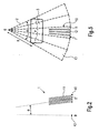
- Fig. 2 shows a section along the YZ plane through the secondary collimator 1.
- vertical slats 11 can be seen, which are parallel to each other.
- These vertical slats 11 are perpendicular to the YZ plane and are around the Spread angle ⁇ inclined to the Z-axis. They are made of an absorbent material, such as steel, and have a thickness of about 100 ⁇ m. Adjacent vertical fins 11 are spaced 1.5 mm apart, which corresponds to the width of a detector element 40 in the Y direction.
- Fig. 3 is a section along the XZ plane shown. This plane contains the point at which the X-ray source O is arranged, as well as the starting point A and the end point B of the detector 4.
- horizontal slats 12 extending a height (perpendicular to the plane shown) of 1.5 mm (as above Fig. 2 described) and a width of about 2 mm at the detector 4 (not shown), which corresponds to the width of a single detector element 40.
- the gaps formed by the vertical slats 11 and the horizontal slats 12 taper in the direction of the X-ray source O.
- the horizontal slats 12 are aligned so that they all point to the X-ray source O.
- the columns are divided into a total of 5 modules 13 of the secondary collimator 1.
- Each module 13 is formed as a fan segment and has an opening angle of 12 °, so that results in a direct subsequent arrangement of the 5 modules 13 as the total opening angle, the 60 ° of the opening angle ⁇ of the fan beam 2.
- a module 13 has an extension of 27 mm in the Y direction and 350 mm at the detector in the X direction and 228 mm in the X direction directly below the conveyor belt (not shown) on which the item of luggage 3 to be checked.
- Each module 13 is combined to form a collimator unit 10 and arranged in a vertical steel container, so that with a precise joining of the modules 13 automatically results in an accuracy of 30 ⁇ m for the columns of the secondary collimator 1.
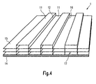
- FIG. 4 is a not yet produced produced Streukollimator 1 shown. Based on this figure, the manufacturing method of a module 13 of a secondary collimator 1 can be well described.
- a first metal sheet 15 is arranged on a robust and rigid base plate 14.
- the first metal sheet 15 is firmly connected to the base plate 14 by means of a known joining method, for example by gluing or spot welding.
- the metal sheet 15 was previously preformed by a traditional metal processing method.
- the metal sheet 15 has been formed so that always alternately below each other at 90 ° vertical slats 11 and horizontal slats 12 are formed. These are each connected to each other via a straight folded edge 16.
- the vertical louvers 11 extend in two mutually parallel planes with always alternately a vertical lamella 11 in the upper plane and then in the lower plane.
- the horizontal slats 12 are not parallel to each other but converge on the X-ray source O (not shown).
- the preformed metal sheet 15 is accurately fixed by means of a template formed of "forks" inserted in the gaps 17.
- an identically preformed metal sheet 15 is precisely placed over the last attached metal sheet 15 and held by means of the above-described template during bonding exactly at this point and firmly connected by means of one of the aforementioned connection method with the sheet metal 15 attached underneath.
- This method is repeated until all the metal sheets 15 are precisely stacked.
- Regularly 18 metal sheets 15 are arranged one above the other, so that the number of segments of the Detector 4 is achieved in the Y direction.
- a cover plate (not shown) is applied and connected to this metal sheet 15 as the base plate 14 with the first metal sheet 15. This gives a two-dimensional grid structure of the metal sheets 15, through which the entire module 13 is stable even under its own weight.
- the angle of the scattering point P is imaged onto the X coordinate of the detector field 40 by a secondary collimator 1 according to the invention and the distance R of the scattering point P from the X-ray source O is imaged onto the X coordinate of the detector field 40.
- the secondary collimator 1 drops only a small angle range around the scattering angle ⁇ in the detector 4.
- a secondary collimator 1 according to the invention is at the same time mechanically extremely stable, which leads to a high-precision XRD profile.
- the secondary collimator 1 according to the invention is very easy to manufacture and of modular construction. It can thus be done by the choice of the number of modules used 13 to adapt to the available financial resources, the number of modules used 13 is directly related to the test speed of the baggage item 3.
Landscapes
- Physics & Mathematics (AREA)
- Health & Medical Sciences (AREA)
- Life Sciences & Earth Sciences (AREA)
- Chemical & Material Sciences (AREA)
- Analytical Chemistry (AREA)
- Biochemistry (AREA)
- General Health & Medical Sciences (AREA)
- General Physics & Mathematics (AREA)
- Immunology (AREA)
- Pathology (AREA)
- Spectroscopy & Molecular Physics (AREA)
- Engineering & Computer Science (AREA)
- General Engineering & Computer Science (AREA)
- High Energy & Nuclear Physics (AREA)
- Analysing Materials By The Use Of Radiation (AREA)
- Measurement Of Radiation (AREA)
Claims (10)
- Collimateur secondaire (1) pour un dispositif à rayons X avec des lamelles horizontales (12) et des lamelles verticales (11) disposées perpendiculairement par rapport à celles-ci, les lamelles verticales (11) étant disposées parallèlement entre elles et étant inclinées d'un angle de diffusion (Θ) prédéfini par rapport à une direction de transmission d'un rayon X, et les lamelles horizontales (12) étant orientées sur un point unique, notamment vers une source de rayons X (O), dans la position de montage du collimateur secondaire (1), et les lamelles horizontales (12) formant avec les lamelles verticales (11) un quadrillage à angle droit et étant intégrées dans une unité de collimateur (10),
caractérisé en ce qu'un certain nombre de tôles métalliques (15) sont disposées sur une plaque de base (14) rigide, solide présentant des surfaces pliées, chaque surface se jouxtant respectivement étant perpendiculaire aux autres et la première tôle métallique (15) étant reliée fixement à la plaque de base (14) et la deuxième tôle métallique (15) étant reliée fixement à la première tôle métallique (15) et la tôle métallique (15) respective suivante étant reliée fixement à la précédente, les parties des tôles métalliques (15) orientées parallèlement à la plaque de base (14) formant les lamelles verticales (11) et les parties des tôles métalliques (15) orientées de façon perpendiculaire à la plaque de base (15) formant les lamelles horizontales (12). - Collimateur secondaire (1) selon la revendication 1, caractérisé en ce que les lamelles (11 ; 12) sont fabriquées à partir d'un matériau absorbant les rayons X, notamment en acier, et présentent une épaisseur inférieure à 1 mm, notamment d'environ 100 µm.
- Collimateur secondaire (1) selon l'une quelconque des revendications 1 ou 2, caractérisé en ce que le quadrillage à angle droit présente au niveau d'une première extrémité, correspondant en position de montage du collimateur secondaire (1) à l'extrémité éloignée des sources de rayons, X, une largeur de 1 - 10 mm dans la direction horizontale, et dans la direction verticale une hauteur de 0,5 - 2,5 mm par élément de quadrillage.
- Collimateur secondaire (1) selon l'une quelconque des revendications précédentes, caractérisé en ce que l'unité de collimateur (10) présente au niveau de la première extrémité, correspondant dans la position de montage du collimateur secondaire (1) à l'extrémité éloignée des sources de rayons X, une largeur globale de 350 mm en direction des lamelles verticales (11) tout en présentant au niveau d'une seconde extrémité, correspondant en position de montage du collimateur secondaire (1) à l'extrémité proche des sources de rayons X, une largeur globale de 228 mm en direction des lamelles verticales (11) ainsi qu'en direction de la source de rayons X (O) une hauteur totale de 250 mm et possède un angle d'ouverture (α) de 12°.
- Collimateur secondaire (1) selon l'une quelconque des revendications précédentes, caractérisé en ce que cinq unités de collimateur (10) sont insérées les unes à côté des autres et en ce qu'elles présentent un angle d'ouverture (α) total de 60°.
- Collimateur secondaire (1) selon l'une quelconque des revendications précédentes, caractérisé en ce que 18 tôles métalliques (15) au total sont disposées sur la plaque de base (14).
- Collimateur secondaire (1) selon l'une quelconque des revendications précédentes, caractérisé en ce que la tôle métallique (15) est reliée fixement à une plaque de recouvrement rigide, solide au niveau de l'extrémité du collimateur secondaire opposée à la plaque de base (14).
- Dispositif à rayons X diffusés destiné au contrôle des bagages à l'aide d'une source de rayons X (O), avec un collimateur primaire ne laissant passer qu'un faisceau en éventail (2), avec un collimateur secondaire (1) pour reproduire une zone de bagage (3) à examiner et avec un détecteur de diffusion (4), le collimateur secondaire (1) étant disposé entre la zone du bagage (3) à examiner et le détecteur de diffusion (4) et étant réalisé selon l'une quelconque des revendications précédentes.
- Dispositif à rayons X diffusés selon la revendication 8, caractérisé en ce qu'un détecteur de transmission (43) est disposé en plus dans le prolongement rectiligne de la source de rayons X (O) au-dessus de la zone du bagage (3) à examiner.
- Dispositif à rayons X diffusés selon l'une quelconque des revendications 8 ou 9, caractérisé en ce que le collimateur secondaire (1) est orienté dans la direction verticale dans laquelle les lamelles verticales (11) sont orientées, parallèlement au faisceau en éventail (2), et est orienté dans la direction horizontale dans laquelle les lamelles horizontales (12) sont orientées ainsi que dans la direction perpendiculaire à la direction verticale sur la zone du bagage (3) à examiner.
Applications Claiming Priority (2)
| Application Number | Priority Date | Filing Date | Title |
|---|---|---|---|
| DE102004014445 | 2004-03-24 | ||
| DE102004014445A DE102004014445B4 (de) | 2004-03-24 | 2004-03-24 | Sekundärkollimator für eine Röntgenstreuvorrichtung sowie Röntgenstreuvorrichtung |
Publications (3)
| Publication Number | Publication Date |
|---|---|
| EP1580765A2 EP1580765A2 (fr) | 2005-09-28 |
| EP1580765A3 EP1580765A3 (fr) | 2006-08-16 |
| EP1580765B1 true EP1580765B1 (fr) | 2008-03-26 |
Family
ID=34854026
Family Applications (1)
| Application Number | Title | Priority Date | Filing Date |
|---|---|---|---|
| EP05006638A Ceased EP1580765B1 (fr) | 2004-03-24 | 2005-03-24 | Collimateur secondaire pour dispositif à rayons X diffusés et dispositif à rayons X diffusés |
Country Status (3)
| Country | Link |
|---|---|
| US (1) | US7463721B2 (fr) |
| EP (1) | EP1580765B1 (fr) |
| DE (1) | DE102004014445B4 (fr) |
Families Citing this family (12)
| Publication number | Priority date | Publication date | Assignee | Title |
|---|---|---|---|---|
| US7359488B1 (en) * | 2004-05-25 | 2008-04-15 | Michel Sayag | Technique for digitally removing x-ray scatter in a radiograph |
| US7653176B2 (en) * | 2005-06-14 | 2010-01-26 | L-3 Communications Security and Detection Systems Inc. | Inspection system with material identification |
| US7436932B2 (en) * | 2005-06-24 | 2008-10-14 | Varian Medical Systems Technologies, Inc. | X-ray radiation sources with low neutron emissions for radiation scanning |
| US7773724B2 (en) | 2006-07-11 | 2010-08-10 | Morpho Detection, Inc. | Systems and methods for generating an improved diffraction profile |
| US7881437B2 (en) * | 2006-07-11 | 2011-02-01 | Morpho Detection, Inc. | Systems and methods for developing a primary collimator |
| US7889845B2 (en) * | 2007-12-20 | 2011-02-15 | Morpho Detection, Inc. | Secondary collimator and method of assembling the same |
| US7835495B2 (en) * | 2008-10-31 | 2010-11-16 | Morpho Detection, Inc. | System and method for X-ray diffraction imaging |
| US7787591B2 (en) * | 2008-12-01 | 2010-08-31 | Morpho Detection, Inc. | Primary collimator and systems for x-ray diffraction imaging, and method for fabricating a primary collimator |
| US20110188632A1 (en) * | 2010-02-03 | 2011-08-04 | Geoffrey Harding | Multiple plane multi-inverse fan-beam detection systems and method for using the same |
| US8223925B2 (en) | 2010-04-15 | 2012-07-17 | Bruker Axs Handheld, Inc. | Compact collimating device |
| EP3933881A1 (fr) | 2020-06-30 | 2022-01-05 | VEC Imaging GmbH & Co. KG | Source de rayons x à plusieurs réseaux |
| US12230468B2 (en) | 2022-06-30 | 2025-02-18 | Varex Imaging Corporation | X-ray system with field emitters and arc protection |
Family Cites Families (18)
| Publication number | Priority date | Publication date | Assignee | Title |
|---|---|---|---|---|
| US4057726A (en) * | 1975-12-22 | 1977-11-08 | G. D. Searle & Co. | Collimator trans-axial tomographic scintillation camera |
| JPS5940284A (ja) * | 1982-08-31 | 1984-03-05 | Shimadzu Corp | 放射線結像装置用コリメ−タ |
| EP0311177B1 (fr) * | 1987-10-05 | 1993-12-15 | Philips Patentverwaltung GmbH | Système pour examiner un corps avec une source de rayonnement |
| JPH03120500A (ja) * | 1989-10-04 | 1991-05-22 | Toshiba Corp | 多孔コリメータ及びその製造方法 |
| DE58906047D1 (de) * | 1989-08-09 | 1993-12-02 | Heimann Systems Gmbh & Co | Vorrichtung zum Durchstrahlen von Gegenständen mittels fächerförmiger Strahlung. |
| US5231655A (en) * | 1991-12-06 | 1993-07-27 | General Electric Company | X-ray collimator |
| EP0556887B1 (fr) * | 1992-02-06 | 1998-07-08 | Philips Patentverwaltung GmbH | Dispositif pour la mesure du spectre de transfert d'impulsions de quantor de rayonnement X |
| GB2297835A (en) * | 1995-02-08 | 1996-08-14 | Secr Defence | Three dimensional detection of contraband using x rays |
| DE19510168C2 (de) * | 1995-03-21 | 2001-09-13 | Heimann Systems Gmbh & Co | Verfahren und Vorrichtung zur Bestimmung von kristallinen und polykristallinen Materialien in einem Untersuchungsbereich |
| US5949850A (en) * | 1997-06-19 | 1999-09-07 | Creatv Microtech, Inc. | Method and apparatus for making large area two-dimensional grids |
| WO1999039189A2 (fr) * | 1998-01-28 | 1999-08-05 | American Science And Engineering, Inc. | Emission intermittente et detection de dispersion pour l'imagerie par rayons x |
| EP0984302B1 (fr) | 1998-09-04 | 2003-08-20 | YXLON International X-Ray GmbH | Dispositif et appareil d'analyse de bagage aux rayons X |
| EP1192479B1 (fr) * | 1999-03-15 | 2013-05-29 | Philips Digital Mammography Sweden AB | Dispositif et procede d'imagerie par rayons x |
| US6470072B1 (en) * | 2000-08-24 | 2002-10-22 | General Electric Company | X-ray anti-scatter grid |
| WO2002065480A1 (fr) * | 2001-02-01 | 2002-08-22 | Creatv Microtech, Inc. | Modeles de collimateurs et de grilles antidiffusion, et leur deplacement, fabrication et assemblage |
| DE10136946A1 (de) | 2001-07-28 | 2003-02-06 | Philips Corp Intellectual Pty | Streustrahlenraster für eine Röntgeneinrichtung |
| EP1347287B1 (fr) * | 2002-02-26 | 2004-07-14 | YXLON International Security GmbH | Diffusion cohérente de rayons X avec multifocalisation simultanée (CXRS) |
| DE10241423B4 (de) | 2002-09-06 | 2007-08-09 | Siemens Ag | Verfahren zur Herstellung und Aufbringung eines Streustrahlenrasters oder Kollimators auf einen Röntgen- oder Gammadetektor |
-
2004
- 2004-03-24 DE DE102004014445A patent/DE102004014445B4/de not_active Expired - Fee Related
-
2005
- 2005-03-24 US US11/090,445 patent/US7463721B2/en not_active Expired - Fee Related
- 2005-03-24 EP EP05006638A patent/EP1580765B1/fr not_active Ceased
Also Published As
| Publication number | Publication date |
|---|---|
| EP1580765A3 (fr) | 2006-08-16 |
| US20050281383A1 (en) | 2005-12-22 |
| DE102004014445B4 (de) | 2006-05-18 |
| US7463721B2 (en) | 2008-12-09 |
| DE102004014445A1 (de) | 2005-10-13 |
| EP1580765A2 (fr) | 2005-09-28 |
Similar Documents
| Publication | Publication Date | Title |
|---|---|---|
| EP1107260B1 (fr) | Grille absorbant les rayons-x | |
| EP1241470B1 (fr) | Dispositif de mesure du transfert d'impulsion lors de la diffusion élastique de quantas de rayons x dans la région d' un conteneur à inspecter | |
| DE102010047205B4 (de) | Sekundärkollimator und Verfahren desselben | |
| EP1580765B1 (fr) | Collimateur secondaire pour dispositif à rayons X diffusés et dispositif à rayons X diffusés | |
| DE3689231T2 (de) | Röntgenstrahlquelle. | |
| DE19604802A1 (de) | System und Verfahren für eine Schichtbildaufnahme mit durchgehender linearer Abtastung | |
| EP3176606B1 (fr) | Procédé destiné à l'alignement d'un scanner laser | |
| DE10303438A1 (de) | Röntgenfluoreszenzspektrometer für Halbleiter | |
| DE3705423A1 (de) | Verfahren zum ausrichten eines roentgenstrahlendetektors mit einem linearen feld | |
| DE19901901A1 (de) | Verfahren und Gerät zur Desensibilisierung von Einfallwinkelfehlern bei einer Mehrschnitt-Computer-Tomographie-Erfassungseinrichtung | |
| DE102005009817B4 (de) | Lochmaske für einen Röntgenstrahlendetektor, Computertomographiegerät, aufweisend eine Lochmaske und Verfahren zur Justierung einer Lochmaske | |
| DE10164245A1 (de) | Verfahren zum Kompensieren eines Spaltes bei volumetrischen Mehrfachplatten-CT-Abtastern und zugehörige Vorrichtung | |
| DE19964395B4 (de) | Rechnergestütztes Tomographieverfahren | |
| DE69608949T2 (de) | Verfahren und vorrichtung zur bestimmung wenigstens eines charakteristischen parameters eines körpers | |
| DE102010051774B4 (de) | Röntgenzeilendetektor | |
| EP2913632B1 (fr) | Procédé de mesure d'un objet par fluorescence de rayons X | |
| DE102005011467B4 (de) | Kollimator mit einstellbarer Brennweite, hierauf gerichtetes Verfahren sowie Röntgenprüfanlage | |
| DE10125454A1 (de) | Gerät zur Röntgenanalyse mit einem Mehrschichtspiegel und einem Ausgangskollimator | |
| DE10221200B4 (de) | Röntgenfluoreszenzspektrometer | |
| WO2020169559A1 (fr) | Dispositif de mesure de rayonnement x pour une mesure 1d continue | |
| EP1100092B1 (fr) | Dispositif de guidage de rayons-x | |
| DE202018000265U1 (de) | Streustrahlenflter für einen Röntgendetektor eines Röntgengeräts, Röntgendetektor und Röntgengerät | |
| DE3140714A1 (de) | Vorrichtung zur dickenmessung von flachprofilen | |
| DE102005039642B3 (de) | Kollimatorensystem für eine Röntgendiffraktometrie, Röntgenbeugungsscanner sowie Verfahren zur Durchführung einer Röntgenbeugungsanalyse | |
| DE3124998A1 (de) | Streustrahlenraster |
Legal Events
| Date | Code | Title | Description |
|---|---|---|---|
| PUAI | Public reference made under article 153(3) epc to a published international application that has entered the european phase |
Free format text: ORIGINAL CODE: 0009012 |
|
| AK | Designated contracting states |
Kind code of ref document: A2 Designated state(s): AT BE BG CH CY CZ DE DK EE ES FI FR GB GR HU IE IS IT LI LT LU MC NL PL PT RO SE SI SK TR |
|
| AX | Request for extension of the european patent |
Extension state: AL BA HR LV MK YU |
|
| PUAL | Search report despatched |
Free format text: ORIGINAL CODE: 0009013 |
|
| AK | Designated contracting states |
Kind code of ref document: A3 Designated state(s): AT BE BG CH CY CZ DE DK EE ES FI FR GB GR HU IE IS IT LI LT LU MC NL PL PT RO SE SI SK TR |
|
| AX | Request for extension of the european patent |
Extension state: AL BA HR LV MK YU |
|
| RIC1 | Information provided on ipc code assigned before grant |
Ipc: G01N 23/201 20060101ALI20060712BHEP Ipc: G21K 1/02 20060101AFI20050705BHEP Ipc: G01V 5/00 20060101ALI20060712BHEP |
|
| 17P | Request for examination filed |
Effective date: 20070216 |
|
| 17Q | First examination report despatched |
Effective date: 20070320 |
|
| AKX | Designation fees paid |
Designated state(s): GB |
|
| REG | Reference to a national code |
Ref country code: DE Ref legal event code: 8566 |
|
| RAP1 | Party data changed (applicant data changed or rights of an application transferred) |
Owner name: GE HOMELAND PROTECTION, INC. |
|
| GRAP | Despatch of communication of intention to grant a patent |
Free format text: ORIGINAL CODE: EPIDOSNIGR1 |
|
| GRAS | Grant fee paid |
Free format text: ORIGINAL CODE: EPIDOSNIGR3 |
|
| GRAA | (expected) grant |
Free format text: ORIGINAL CODE: 0009210 |
|
| AK | Designated contracting states |
Kind code of ref document: B1 Designated state(s): GB |
|
| REG | Reference to a national code |
Ref country code: GB Ref legal event code: FG4D Free format text: NOT ENGLISH |
|
| PLBE | No opposition filed within time limit |
Free format text: ORIGINAL CODE: 0009261 |
|
| STAA | Information on the status of an ep patent application or granted ep patent |
Free format text: STATUS: NO OPPOSITION FILED WITHIN TIME LIMIT |
|
| 26N | No opposition filed |
Effective date: 20081230 |
|
| PGFP | Annual fee paid to national office [announced via postgrant information from national office to epo] |
Ref country code: GB Payment date: 20100625 Year of fee payment: 6 |
|
| GBPC | Gb: european patent ceased through non-payment of renewal fee |
Effective date: 20110324 |
|
| PG25 | Lapsed in a contracting state [announced via postgrant information from national office to epo] |
Ref country code: GB Free format text: LAPSE BECAUSE OF NON-PAYMENT OF DUE FEES Effective date: 20110324 |
|
| P01 | Opt-out of the competence of the unified patent court (upc) registered |
Effective date: 20230528 |