EP1580546B1 - Methoden zur Röntgenreflexionsmessung - Google Patents
Methoden zur Röntgenreflexionsmessung Download PDFInfo
- Publication number
- EP1580546B1 EP1580546B1 EP05006099.5A EP05006099A EP1580546B1 EP 1580546 B1 EP1580546 B1 EP 1580546B1 EP 05006099 A EP05006099 A EP 05006099A EP 1580546 B1 EP1580546 B1 EP 1580546B1
- Authority
- EP
- European Patent Office
- Prior art keywords
- ray
- measurement
- time length
- measuring time
- cps
- Prior art date
- Legal status (The legal status is an assumption and is not a legal conclusion. Google has not performed a legal analysis and makes no representation as to the accuracy of the status listed.)
- Expired - Lifetime
Links
- 238000005259 measurement Methods 0.000 title claims description 103
- 238000000034 method Methods 0.000 title claims description 33
- 239000010409 thin film Substances 0.000 description 18
- 239000010408 film Substances 0.000 description 10
- 238000004458 analytical method Methods 0.000 description 9
- 230000003746 surface roughness Effects 0.000 description 7
- 239000000758 substrate Substances 0.000 description 6
- ATJFFYVFTNAWJD-UHFFFAOYSA-N Tin Chemical compound [Sn] ATJFFYVFTNAWJD-UHFFFAOYSA-N 0.000 description 5
- 238000001514 detection method Methods 0.000 description 5
- PBCFLUZVCVVTBY-UHFFFAOYSA-N tantalum pentoxide Inorganic materials O=[Ta](=O)O[Ta](=O)=O PBCFLUZVCVVTBY-UHFFFAOYSA-N 0.000 description 5
- XUIMIQQOPSSXEZ-UHFFFAOYSA-N Silicon Chemical compound [Si] XUIMIQQOPSSXEZ-UHFFFAOYSA-N 0.000 description 3
- 238000010521 absorption reaction Methods 0.000 description 3
- 230000003287 optical effect Effects 0.000 description 3
- 229910052710 silicon Inorganic materials 0.000 description 3
- 239000010703 silicon Substances 0.000 description 3
- 238000002441 X-ray diffraction Methods 0.000 description 2
- 230000000052 comparative effect Effects 0.000 description 2
- 230000001419 dependent effect Effects 0.000 description 2
- 238000003780 insertion Methods 0.000 description 2
- 230000037431 insertion Effects 0.000 description 2
- 230000010287 polarization Effects 0.000 description 2
- 229920006395 saturated elastomer Polymers 0.000 description 2
- NRTOMJZYCJJWKI-UHFFFAOYSA-N Titanium nitride Chemical compound [Ti]#N NRTOMJZYCJJWKI-UHFFFAOYSA-N 0.000 description 1
- 238000000098 azimuthal photoelectron diffraction Methods 0.000 description 1
- 230000005493 condensed matter Effects 0.000 description 1
- 238000002474 experimental method Methods 0.000 description 1
- 238000001093 holography Methods 0.000 description 1
- 230000007774 longterm Effects 0.000 description 1
- 238000004519 manufacturing process Methods 0.000 description 1
- BPUBBGLMJRNUCC-UHFFFAOYSA-N oxygen(2-);tantalum(5+) Chemical compound [O-2].[O-2].[O-2].[O-2].[O-2].[Ta+5].[Ta+5] BPUBBGLMJRNUCC-UHFFFAOYSA-N 0.000 description 1
- 230000000737 periodic effect Effects 0.000 description 1
- 238000012552 review Methods 0.000 description 1
- 239000004065 semiconductor Substances 0.000 description 1
- 230000005469 synchrotron radiation Effects 0.000 description 1
- 229910001936 tantalum oxide Inorganic materials 0.000 description 1
Images


Classifications
-
- G—PHYSICS
- G01—MEASURING; TESTING
- G01N—INVESTIGATING OR ANALYSING MATERIALS BY DETERMINING THEIR CHEMICAL OR PHYSICAL PROPERTIES
- G01N23/00—Investigating or analysing materials by the use of wave or particle radiation, e.g. X-rays or neutrons, not covered by groups G01N3/00 – G01N17/00, G01N21/00 or G01N22/00
- G01N23/20—Investigating or analysing materials by the use of wave or particle radiation, e.g. X-rays or neutrons, not covered by groups G01N3/00 – G01N17/00, G01N21/00 or G01N22/00 by using diffraction of the radiation by the materials, e.g. for investigating crystal structure; by using scattering of the radiation by the materials, e.g. for investigating non-crystalline materials; by using reflection of the radiation by the materials
-
- G—PHYSICS
- G01—MEASURING; TESTING
- G01N—INVESTIGATING OR ANALYSING MATERIALS BY DETERMINING THEIR CHEMICAL OR PHYSICAL PROPERTIES
- G01N23/00—Investigating or analysing materials by the use of wave or particle radiation, e.g. X-rays or neutrons, not covered by groups G01N3/00 – G01N17/00, G01N21/00 or G01N22/00
- G01N23/02—Investigating or analysing materials by the use of wave or particle radiation, e.g. X-rays or neutrons, not covered by groups G01N3/00 – G01N17/00, G01N21/00 or G01N22/00 by transmitting the radiation through the material
- G01N23/06—Investigating or analysing materials by the use of wave or particle radiation, e.g. X-rays or neutrons, not covered by groups G01N3/00 – G01N17/00, G01N21/00 or G01N22/00 by transmitting the radiation through the material and measuring the absorption
- G01N23/083—Investigating or analysing materials by the use of wave or particle radiation, e.g. X-rays or neutrons, not covered by groups G01N3/00 – G01N17/00, G01N21/00 or G01N22/00 by transmitting the radiation through the material and measuring the absorption the radiation being X-rays
- G01N23/085—X-ray absorption fine structure [XAFS], e.g. extended XAFS [EXAFS]
-
- G—PHYSICS
- G01—MEASURING; TESTING
- G01T—MEASUREMENT OF NUCLEAR OR X-RADIATION
- G01T1/00—Measuring X-radiation, gamma radiation, corpuscular radiation, or cosmic radiation
- G01T1/16—Measuring radiation intensity
- G01T1/24—Measuring radiation intensity with semiconductor detectors
- G01T1/242—Stacked detectors, e.g. for depth information
Definitions
- the present invention relates to a method for measuring an X-ray reflectance in a short time with the use of an X-ray detector having a high upper-limit counting rate, and a method for measuring an X-ray reflectance with a high dynamic range with the use of an X-ray detector having a low noise level.
- An X-ray reflectance curve can be determined in a manner that a reflected X-ray intensity is measured with the scanning of the scattering angle 2 ⁇ in a range between zero to five degrees for instance. If a reflected X-ray intensity is measured at 0.01-degree intervals in 2 ⁇ and a measuring time length per interval is set to be one second, there is required, for the range between zero to five degrees, five-hundred measurement steps, the total time required for the measurement being five-hundred seconds. As just described, it takes ordinarily around several minutes to determine one reflectance curve.
- An X-ray detector may be, for instance, a proportional counter or a scintillation counter.
- the present invention is concerned with the use of an avalanche photo diode as an X-ray detector, the avalanche photo diode being abbreviated to "APD" hereinafter.
- An X-ray analytical apparatus using the APD as an X-ray detector is known and disclosed in, for instance, Japanese patent publication No. 2004-37360 A , which will be referred to as the second publication.
- the second publication discloses that a fluorescent X-ray holography detection system uses the APD having a high counting rate so as to complete the measurement in a shorter time than before. It says in the second publication that since the counting rate of the APD is high as not less than 10 6 cps, the time required for detecting an X-ray at any measuring point is not more than one second and the total measuring time is reduced from around two months to around several hours when the fluorescent X-ray intensity is measured even under many angular conditions.
- the X-ray reflectance measurement must be carried out for many measuring positions on a single substrate to analyze the properties of the thin film, such as a film thickness for instance, for respective measuring positions. Assuming that it takes several minutes for the measurement at one measuring position, it takes several dozen minutes for the measurements at ten measuring positions. If the time required for the measurement at one measuring position is reduced to several seconds, it would take mere several dozen seconds for the measurements at ten measuring positions, completing the total measurement process in a very short time. Such a short-time measurement has been desired.
- the APD having a high counting rate to reduce the measuring time as disclosed in the second publication.
- the second publication is, however, concerned with the special use as detecting very small fluorescent X-ray hologram signal, in which the long-term measuring time of around two months with the use of the ordinary detector has been reduced to the several hours with the use of the APD. It is noted that, even using the APD, there is needed around one second for one step of the X-ray intensity measurement in the fluorescent X-ray hologram.
- S. KISHIMOTO, N. ISHIZAWA, T.P. VAALSTA "A fast detector using stacked avalanche photodiodes (APD) for x-ray diffraction experiments with synchrotron radiation”.
- APD stacked avalanche photodiodes
- REVIEW OF SCIENTIFIC INSTRUMENTS, vol. 69, no. 2, February 1998 (1998-02), pages 384-391 , XP002333237” discloses a detector withhas four independent channels of APDs and the detector efficiency has reached 55 % in all for 16.53 keV x-rays. Since the dead time of the counting system is shorter than 4ns, output rates of up to 4.5 x 10 8 counts/s have been obtained for 16.53 keV x rays. The dynamic range is more than 10 10 in the multibunch mode of a storage ring. Pulse-heigt measurements at output rates of up to 10 8 counts/s were successfully carried out by sequential single-channel discrimination.
- the detector can count x-rays at rates of 10 7 photons s -1 , giving good estimates of the resonant x-ray magnetic scattering at superlattice Bragg peaks in a reasonable short time when count losses due to the time structure of the synchrotron x-rays are corrected for.
- the present invention is characterized in that an X-ray reflectance is measured with the use of an X-ray detector having a high counting rate.
- the present invention has the feature that a desired dynamic range is assured even when the measuring time length per interval is very short.
- a method for X-ray reflectance measurement according the present invention is defined in claim 1. Further embodiments of the invention are claimed in the dependent claims.
- an X-ray detector which is not less than 10 7 cps in upper-limit counting rate and is not more than twenty cps in noise level converted to the counting rate, and an X-ray reflectance is measured with the use of the X-ray detector under the condition that a measuring time length per interval of a scattering angle 2 ⁇ is not more than fifty milliseconds.
- the X-ray detector having such a property may be the APD. It is noted that cps as the unit of the counting rate suggests count per second.
- Values of the measured X-ray reflectance remarkably vary with the scattering angle 2 ⁇ and the dynamic range for the values often becomes around a five-digit number or over. It is important, for measuring such an X-ray reflectance in a very short time as several seconds for instance, to carry out the measurement at one burst with the 2 ⁇ scanning only, without the insertion or removal of an absorption plate in the middle of the measurement operation. Accordingly, the measurement should be carried out with a high dynamic range and therefore there is required an X-ray detector having an upper-limit counting rate of not less than 10 7 cps.
- the measuring time length at any interval of the scattering angle 2 ⁇ is ten milliseconds for instance, it is required, for detecting one-count X-ray photon during the measuring time length, that an X-ray having an intensity of more than a hundred cps must be incident on the X-ray detector, the hundred cps having been calculated by the division of one count by ten milliseconds. In other words, it is impossible to detect an X-ray having an intensity of not more than a hundred cps in the measuring time length of ten milliseconds, the hundred cps being defined as the lower-limit counting rate for the ten-millisecond measuring time length.
- the upper-limit counting rate of the X-ray detector is high as not less than 10 7 cps, a 10 5 dynamic range, i.e., five-digit dynamic range, can be ensured even in the very short measuring time length as the ten milliseconds, noting that the dynamic range is defined as a ratio of the upper-limit counting rate to the lower-limit counting rate and the 10 5 dynamic range has been calculated by the division of the 10 7 cps by the hundred cps. If the upper-limit counting rate is higher as 10 8 cps, a six-digit dynamic range is ensured. If the upper-limit counting rate is further higher as 10 9 cps, a seven-digit dynamic range is ensured.
- the noise level of the X-ray detector should be not more than the hundred cps for the accurate detection of the X-ray intensity with the ten-millisecond measuring time length.
- the present invention focuses on the reduction of the measuring time length per interval, which is set to be not more than fifty milliseconds, so that even when the measurement is carried out at 0.01-degree intervals in scattering angle 2 ⁇ , a five-second term is enough for the measurement per degree.
- a two-point-five-second term is enough per degree.
- a seven-point-five-second term is enough as the total time for measuring a reflectance curve in a range between zero to three degrees in scattering angle 2 ⁇ .
- the lower-limit counting rate becomes twenty cps, namely, it is impossible to detect an X-ray intensity of not more than twenty cps. Accordingly, there is no problem if the inherent noise level of the X-ray detector is not more than twenty cps.
- the upper-limit counting rate of the X-ray detector is not less than 10 7 cps. Therefore, the measurable dynamic range is five times 10 5 , which has been calculated by the division of 10 7 by twenty. Assuming that the measuring time length per interval is reduced to ten milliseconds, the lower-limit counting rate comes up to a hundred cps, still ensuring a five-digit measurable dynamic range.
- the measuring time length per interval it is preferable, for ensuring a desired dynamic range and reducing the measurement time, to set the measuring time length per interval to be one through fifty milliseconds, more preferably five through twenty milliseconds.
- An alternative method for X-ray reflectance measurement includes the steps of preparing an X-ray detector which is not less than 10 7 cps in upper-limit counting rate and is not more than 0.01 cps in noise level converted to the counting rate, and measuring an X-ray reflectance with the use of the X-ray detector under the condition that the maximum measuring time length per interval of scattering angle 2 ⁇ is not less than a hundred seconds. If the measuring time length per interval is set to be constant for any value of the scattering angle 2 ⁇ , the constant measuring time length corresponds to the maximum measuring time length, which is set to be not less than a hundred seconds in the alternative method.
- the maximum of the varying values of the measuring time length should be not less than a hundred seconds. Since the larger the scattering angle 2 ⁇ the smaller the reflected X-ray intensity, the variation of the measuring time length per interval should be in the condition that the maximum value of the measuring time length per interval appears at the largest value of the scattering angle 2 ⁇ .
- the X-ray detector may be the APD in the alternative method too.
- the above-mentioned alternative method focuses on the high dynamic range for obtaining an X-ray reflectance curve and uses, for this purpose, an X-ray detector which is not less than 10 7 cps in upper-limit counting rate and is not more than 0.01 cps in noise level converted to the counting rate. Assuming that an X-ray intensity can be detected down to the noise level, the lower-limit counting rate is coincide with the noise level, the dynamic range being not less than 10 9 . It should be noted, however, that since the lower-limit counting rate is also determined by the measuring time length per interval, it is important, for getting the most out of the above-mentioned low noise level, to reduce the lower-limit counting rate down to under the low noise level.
- the measuring time length per interval may be at least a value with which the lower-limit counting rate becomes equivalent to the noise level. Accordingly, the measuring time length per interval of not less than a hundred seconds is enough in the case of using an X-ray detector having a noise level of 0.01 cps. If it is intended, however, to measure a reflected X-ray intensity which is far above the noise level, the X-ray detection would not be disturbed by the noise level even when the measuring time length per interval is reduced to under a hundred seconds.
- the alternative method has the feature that the "maximum value" of the measuring time length per interval is not less than a hundred seconds. The maximum value should appear at the largest point in a range of the scattering angle 2 ⁇ in which one reflectance curve will be measured.
- the present invention has an advantage that an X-ray reflectance can be measured in a short time as around several seconds. Accordingly, when it is intended to measure the X-ray reflectance for many positions on the substrate, the total time required is remarkably reduced.
- the alternative method has an advantage that an X-ray reflectance can be measured with an extremely high dynamic range as not less than 10 9 , enabling a high-accuracy analysis of the thin film properties.
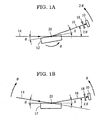
- FIGs. 1A and 1B illustrate two arrangements of an optical system in a method for X-ray reflectance measurement according to the present invention.
- an X-ray detector 10 is an APD.
- An X-ray 14 is incident on the surface of a sample 12 at a small incident angle ⁇ .
- An X-ray 16 reflected at the surface of the sample 12 passes through a receiving slit 18 and is detected by the APD 10, the slit 18 and the APD 10 being positioned at an outgoing angle ⁇ from the surface of the sample 12.
- An assembly consisting of the receiving slit 18 and the APD 10 will be referred to as a receiving system hereinafter.
- An angle between the incident X-ray 14 and the reflected X-ray 16 is a scattering angle 2 ⁇ .
- the scattering angle 2 ⁇ is scanned in a manner that the sample 12 is rotated with a ⁇ -rotation around the center 20 of a goniometer while the receiving system is rotated around the center 20 of the goniometer with a 2 ⁇ -rotation.
- Fig. 1B illustrates another method for scanning the scattering angle 2 ⁇ .
- the sample 12 is set to be stationary relative to the space in Fig. 1B although the incident X-ray 14 in Fig. 1A is set to be stationary relative to the space.
- the scattering angle 2 ⁇ is scanned in Fig 1B in a manner that the incident X-ray 14, i.e., an X-ray source, is rotated clockwise with a ⁇ -rotation around the center 20 of the goniometer while the receiving system is rotated counterclockwise with a ⁇ -rotation around the center 20 of the goniometer.
- the method for X-ray reflectance measurement according to the present invention is applicable to any one of the scanning methods shown in Figs. 1A and 1B .
- the present invention has the feature of a higher scanning speed than the ordinary X-ray reflectance measurement.
- a time required for the scanning from zero to five degrees in 2 ⁇ is short as five seconds.
- the sample 12 should be turned at 0.01-degree intervals in the ⁇ -rotation while the receiving system should be turned at 0.02-degree intervals in the 2 ⁇ -rotation.
- the incident X-ray 14 should be turned at 0.01-degree intervals in the clockwise ⁇ -rotation while the receiving system should be turned at 0.01-degree intervals in the counterclockwise ⁇ -rotation.
- the 2 ⁇ -scanning may be carried out with any one of the continuous scanning, in which 2 ⁇ varies continuously during the detection of an X-ray intensity, and the stepwise scanning, in which 2 ⁇ does not vary during the detection of an X-ray intensity. It would be preferable, however, to use the continuous scanning for the present invention because it focuses on short-time measurement.
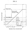
- Fig. 2 is a graph showing exemplarily a relationship between an actual intensity of an incident X-ray on the X-ray detector, measured in cps, and a counting rate which is the output of the X-ray detector, measured also in cps.
- the saturated counting rate is defined as the measurable upper-limit counting rate, which is represented by "upper limit" in Fig. 2 , the value being 10 7 , ten to the seventh power, cps in this embodiment.
- the first factor is the measuring time length per interval
- the second factor is the noise level of the X-ray detector.
- an X-ray intensity of a hundred cps would be required for detecting at least one X-ray photon, the hundred cps having been calculated by the division of the one count by the ten milliseconds.
- the detector cannot detect an X-ray intensity lower than a hundred cps.
- This limit is represented by a horizontal line of ten milliseconds, 10 msec, in Fig. 2 , the lower limit of the counting rate being a hundred cps in this example.
- the measuring time length per interval is set to be a hundred milliseconds
- the lower-limit counting rate becomes ten cps.
- the measuring time length per interval is set to be a thousand milliseconds, i.e., one second, the lower-limit counting rate becomes one cps.
- An X-ray detector has an inherent noise level, and therefore an incident X-ray intensity lower than the inherent noise level cannot be detected because it is hidden by the inherent noise level.
- the graph in Fig. 2 shows an embodiment in which the noise level is around one cps. An incident X-ray intensity lower than the noise level cannot be detected. After all, the larger of the two, the counting rate corresponding to the noise level and the lower-limit counting rate which is determined by the measuring time length per interval, becomes the actual lower-limit counting rate for the measurement in question. Explaining it referring to the graph in Fig.
- the lower-limit counting rate which is determined by the measuring time length per interval is used as the lower-limit counting rate for the measurement in question.
- the counting rate corresponding to the noise level is used as the lower-limit counting rate, which comes not to depend on the measuring time length.
- the solid-line curve in Fig. 2 represents the counting rate when the measuring time length per interval is ten milliseconds, in which the upper limit is 10 7 cps and the lower limit is a hundred cps, ensuring a five-digit measurable dynamic range.
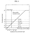
- Fig. 3 is a graph, similar to that in Fig. 2 , for another X-ray detector having a very low noise level as around 0.01 cps, in which even if the measuring time length per interval is set to be considerably long, the counting rate determined by the measuring time length would not be lower than the noise level.
- the solid-line curve in Fig. 3 represents the counting rate when the measuring time length per interval is not less than a hundred seconds. When the measuring time length per interval runs up the hundred seconds, the lower-limit counting rate depending on the measuring time length becomes 0.01 cps at last, which is approximately equal to the noise level.
- the lower-limit counting rate can be reduced to a very low level by prolonging the measuring time length per interval, assuring a very high dynamic range.
- the upper limit is 10 7 cps while the lower limit is 0.01 cps, and thus the measurable dynamic range becomes 10 9 .
- the APD used in the embodiment is 10 8 cps in upper limit and 0.002 cps in noise level. Accordingly, it is possible, with the APD, to shorten the measuring time length per interval to cut down the time required for the X-ray reflectance measurement to be several seconds, and alternatively it is possible to prolong the measuring time length per interval to observe an reflectance curve with a very high dynamic range.
- the incident X-ray will now be described.
- the present invention is characterized by the use of the X-ray detector having the upper-limit counting rate of not less than 10 7 , and thus the invention requires a high-intensity incident X-ray to make active use of the very high upper-limit counting rate.
- the incident X-ray 14 in Figs. 1A and 1B is made a high-intensity X-ray beam which is derived by using a multilayer mirror.
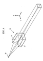
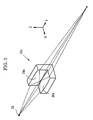
- Fig. 4 is a perspective view of the multilayer mirror used in the embodiment.
- the multilayer mirror 22 is comprised of the first mirror having the parabolic, first reflective surface 24 made of a synthetic multilayer film and the second mirror having the parabolic, second reflective surface 26 made of a synthetic multilayer film, the two mirrors being joined to each other on their lateral edges at an angle of around ninety degrees, so-called a side-by-side multilayer mirror.
- an X-ray beam emitted from the X-ray focus 28 of an X-ray tube which is a divergent beam, can be collimated within an X-Y plane and also within a Y-Z plane.
- the X-ray which has been reflected first at the first reflective surface 24 is reflected at the second reflective surface 26 to go out.
- the X-ray which has been reflected first at the second reflective surface 26 is reflected at the first reflective surface 24 to go out.
- the first reflective surface 24 is for collimating the X-ray within the X-Y plane while the second reflective surface 26 is for collimating the X-ray within the Y-Z plane.
- the divergent X-ray beam from the X-ray focus 28 is collected and collimated by the parabolic surface so as to become a high-intensity parallel beam.
- the multilayer mirror 22 is arranged in the incident optical system so that the X-Y plane in Fig. 4 is positioned to be parallel to the drawing sheet of Figs. 1A and 1B .
- the cross-sectional shape of the incident X-ray beam just before the irradiation of the sample becomes 1 mm times 0.1 mm for instance.
- the divergence angle of the X-ray beam within the X-Y plane and within the Y-Z plane is small as less than 0.03 degree.
- a multilayer mirror 22a shown in Fig. 5 has two elliptical reflective surfaces 24a and 26a.
- the X-ray beam from the multilayer mirror 22a becomes a focused beam which is focused on the surface of the sample within the X-Y plane and within the Y-Z plane.
- the multilayer mirror shown in Fig. 5 can make the incident X-ray intensity higher than that from the multilayer mirror shown in Fig. 4 although the divergence angle becomes larger.
- the cross-sectional shape of the incident X-ray beam just before the irradiation of the sample becomes 0.05 mm times 0.05 mm for instance.
- the divergence angle becomes large as around one degree disadvantageously. It should be noted, however, that a slit can be used to limit the divergence angle to collimate the X-ray beam within the X-Y plane, so that an X-ray reflectance can be measured with around 0.05 degree in divergence angle.
- Fig. 6 is a graph showing X-ray reflectance curves for a Ta 2 O 5 , tantalum oxide, thin film deposited on a silicon substrate, measured by the method shown in Fig. 1A , a scattering angle 2 ⁇ in abscissa while a reflected X-ray intensity represented by the number of counts in ordinate.
- the graph shows four kinds of reflectance curves for the different measuring time lengths, noting that the four curves would substantially overlap each other if the ordinate represents the counting rate, its unit being cps. Since the reflected X-ray intensity is represented by the number of counts, the shorter the measuring time length, i.e., the more the advance from the measurement 1 to the measurement 4, the smaller the reflected X-ray intensity by counts.
- Measurement 1 represents the result measured at 0.01-degree intervals in 2 ⁇ with 500 milliseconds in measuring time length per interval, the scanning speed of 2 ⁇ being 0.02 degree per second accordingly.
- Measurement 2 is for 0.01-degree intervals, 100 milliseconds in measuring time length, and 0.1 degree per second in scanning speed.
- Measurement 3 is for 0.02-degree intervals, 50 milliseconds in measuring time length, and 0.4 degree per second in scanning speed.
- Measurement 4 is for 0.02-degree intervals, 20 milliseconds in measuring time length, and one degree per second in scanning speed. These values are shown together in Table 1 in Fig. 7A .
- the time required for one degree in 2 ⁇ is 50 seconds in measurement 1, 10 seconds in measurement 2, 2.5 seconds in measurement 3 and one second in measurement 4.
- the time required for the range is 250 seconds in measurement 1, 50 seconds in measurement 2, 12.5 seconds in measurement 3 and five seconds in measurement 4. Since the first aspect of the present invention is characterized in that the measuring time length per interval of scattering angle 2 ⁇ is set to be not more than fifty milliseconds, measurements 3 and 4 correspond to embodiments of the first aspect, measurements 1 and 2 being comparative examples. Referring to the graph shown in Fig. 6 , measurements 1 and 2 clearly show the first to the fourth peaks of the interference patterns of the reflectance curves within a range between zero and four degrees in 2 ⁇ . Measurement 3 also clearly shows the first to the fourth peaks although the fourth peak includes some noise overlapping.
- Measurement 4 clearly shows the first to the third peaks although the third peak includes some noise overlapping. As long as such clear data can be observed, it is possible to analyze the thin film properties using reflectance curves such as measurements 3 and 4. It is noted that even measurement 4 would ensure an approximately five-digit dynamic range.
- Fig. 8 is a graph showing X-ray reflectance curves for a TiN, titanium nitride, thin film deposited on a silicon substrate, measured by the method shown in Fig. 1A , a scattering angle 26 in abscissa while a reflected X-ray intensity represented by the number of counts in ordinate.
- the graph shows four kinds of reflectance curves for the different measuring time lengths, noting, similarly to the graph shown in Fig. 6 , that the four curves would substantially overlap each other if the ordinate represents the counting rate, its unit being cps.
- Measurement 1 represents the result measured at 0.01-degree intervals in 2 ⁇ with 1000 milliseconds in measuring time length per interval, the scanning speed of 2 ⁇ being 0.01 degree per second accordingly.
- Measurement 2 is for 0.01-degree intervals, 50 milliseconds in measuring time length, and 0.2 degree per second in scanning speed.
- Measurement 3 is for 0.01-degree intervals, 20 milliseconds in measuring time length, and 0.5 degree per second in scanning speed.
- Measurement 4 is for 0.01-degree intervals, 10 milliseconds in measuring time length, and one degree per second in scanning speed. These values are shown together in Table 2 in Fig. 7B .
- the time required for one degree in 2 ⁇ is 100 seconds in measurement 1, five seconds in measurement 2, two seconds in measurement 3 and one second in measurement 4.
- measurements 2 through 4 correspond to embodiments of the invention, measurement 1 being a comparative example.
- measurements 1 through 3 clearly show the oscillating curves of the interference pattern within a range up to near two degrees in 2 ⁇ .
- Measurement 4 clearly shows the oscillating curve of the interference pattern within a range up to near 1.5 degrees in 2 ⁇ .
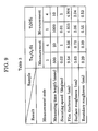
- Fig. 9 shows table 3 which indicates comparison of the results of analysis derived from measurement 1, i.e., a low-speed scanning, and measurement 4, i.e., a high-speed scanning, for the measured data shown in Figs 6 and 8 respectively.
- the properties determined based on the reflectance curve of measurement 1 are as follows: a film thickness is 9.54 nm, a surface roughness is 0.63 nm and a boundary roughness, i.e., a roughness of the boundary between the Ta 2 O 5 thin film and the substrate, is 0.29 nm.
- the properties determined based on the reflectance curve of measurement 4 are as follows: a film thickness is 9.56 nm, a surface roughness is 0.73 nm and a boundary roughness is 0.39 nm. Comparing the film thickness values between the measurements 1 and 4, it is seen that the results of analysis are good consistent with each other. There is no substantial difference between the measurements 1 and 4 regarding the surface roughness and the boundary roughness too. Accordingly, it has been ascertained that even when analysis is carried out based on the reflectance curve observed in a high-speed measurement such as measurement 4, the result of analysis for the thin film properties would possess higher reliability.
- the properties determined based on the reflectance curve of measurement 1 are as follows: a film thickness is 4.935 nm, a surface roughness is 2.06 nm and a boundary roughness is 0.55 nm.
- the properties determined based on the reflectance curve of measurement 4 are as follows: a film thickness is 4.904 nm, a surface roughness is 2.04 nm and a boundary roughness is 0.53 nm.
- the results of analysis are very good consistent with each other between the measurements 1 and 4 regarding the film thickness, the surface roughness and the boundary roughness respectively. Accordingly, it has been ascertained also for TiN that even when analysis is carried out based on the reflectance curve observed in a high-speed measurement such as measurement 4, the result of analysis for the thin film properties would possess higher reliability.
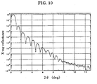
- Fig. 10 is a graph showing an X-ray reflectance curve measured with the use of an APD as an X-ray detector and with taking a sufficient time, a scattering angle 26 in abscissa while a reflectance, i.e., a ratio of a reflected X-ray intensity to an incident X-ray intensity, in ordinate.
- a sample is a Ta 2 O 5 thin film deposited on a silicon substrate and the thickness of the thin film is 10 nm.
- the reflectance is measured at 0.02-degree intervals in 2 ⁇ with ten seconds in measuring time length per interval within a range between zero to six degrees in 2 ⁇ , and at 0.02-degree intervals in 2 ⁇ with a hundred seconds in measuring time length per interval within a range between six to fourteen degrees in 2 ⁇ .
- the time required for a range between zero to six degrees is 3000 seconds while 40000 seconds for a range between six to fourteen degrees, the total time being 43000 seconds which is equal to around 12 hours.
Landscapes
- Chemical & Material Sciences (AREA)
- Health & Medical Sciences (AREA)
- Life Sciences & Earth Sciences (AREA)
- General Physics & Mathematics (AREA)
- Physics & Mathematics (AREA)
- Biochemistry (AREA)
- Pathology (AREA)
- Immunology (AREA)
- General Health & Medical Sciences (AREA)
- Analytical Chemistry (AREA)
- Crystallography & Structural Chemistry (AREA)
- Spectroscopy & Molecular Physics (AREA)
- Molecular Biology (AREA)
- High Energy & Nuclear Physics (AREA)
- Toxicology (AREA)
- Analysing Materials By The Use Of Radiation (AREA)
- Measurement Of Radiation (AREA)
Claims (4)
- Ein Verfahren zur Röntgen-Reflexionsmessung, wobei in dem Verfahren ein Röntgenstrahl (14), der von einer Röntgenröhre emittiert wird, unter einem kleinen Einfallswinkel auf eine Oberfläche einer Probe (12) einfällt, wobei eine Intensität des Röntgenstrahls (16), der an der Oberfläche der Probe (12) reflektiert wird, detektiert wird durch einen Röntgendetektor (10), wobei das Verfahren die folgenden Schritte aufweist:(a) Vorbereiten des Röntgendetektors (10), der eine obere Grenzzählrate nicht kleiner als 107 cps und einen Rauschpegel von nicht mehr als 20 cps aufweist; und(b) Messen einer Röntgenreflexion unter Verwendung des Röntgendetektors (10) unter einer Bedingung, dass eine Messzeitlänge pro Intervall bei einem Streuwinkel 2Θ nicht größer ist als fünfzig Millisekunden.
- Ein Verfahren nach Anspruch 1, wobei die Messzeitlänge pro Intervall bei einem Streuwinkel von 2Θ innerhalb einer Zeitspanne von zwei bis zwanzig Millisekunden liegt.
- Ein Verfahren nach Anspruch 1, wobei der Röntgendetektor (10) eine Lawinenphotodiode (10) ist.
- Ein Verfahren nach Anspruch 1, wobei der Röntgenstrahl (14), der von der Röntgenröhre emittiert wird, an einem Mehrlagenspiegel (22) reflektiert wird, wobei der Mehrlagenspiegel (22) eine parabolische oder eine elliptische, reflektierende Oberfläche (24, 26) aufweist, um hierüber auf die Oberfläche der Probe (12) einzufallen.
Applications Claiming Priority (2)
| Application Number | Priority Date | Filing Date | Title |
|---|---|---|---|
| JP2004081880A JP4041808B2 (ja) | 2004-03-22 | 2004-03-22 | X線反射率の測定方法 |
| JP2004081880 | 2004-03-22 |
Publications (2)
| Publication Number | Publication Date |
|---|---|
| EP1580546A1 EP1580546A1 (de) | 2005-09-28 |
| EP1580546B1 true EP1580546B1 (de) | 2013-09-18 |
Family
ID=34858361
Family Applications (1)
| Application Number | Title | Priority Date | Filing Date |
|---|---|---|---|
| EP05006099.5A Expired - Lifetime EP1580546B1 (de) | 2004-03-22 | 2005-03-21 | Methoden zur Röntgenreflexionsmessung |
Country Status (5)
| Country | Link |
|---|---|
| US (1) | US7221734B2 (de) |
| EP (1) | EP1580546B1 (de) |
| JP (1) | JP4041808B2 (de) |
| KR (1) | KR100994253B1 (de) |
| TW (1) | TWI349773B (de) |
Families Citing this family (3)
| Publication number | Priority date | Publication date | Assignee | Title |
|---|---|---|---|---|
| US7848483B2 (en) * | 2008-03-07 | 2010-12-07 | Rigaku Innovative Technologies | Magnesium silicide-based multilayer x-ray fluorescence analyzers |
| JP2013024721A (ja) * | 2011-07-21 | 2013-02-04 | Seiko Epson Corp | 振動ジャイロ素子、ジャイロセンサー及び電子機器 |
| WO2018101023A1 (ja) | 2016-11-29 | 2018-06-07 | 株式会社リガク | X線反射率測定装置 |
Family Cites Families (3)
| Publication number | Priority date | Publication date | Assignee | Title |
|---|---|---|---|---|
| JP3329197B2 (ja) | 1996-07-19 | 2002-09-30 | 株式会社日立製作所 | 薄膜積層体検査方法 |
| JP3846762B2 (ja) | 1998-02-19 | 2006-11-15 | 株式会社リガク | X線測定装置における測定データ処理方法 |
| JP2004037360A (ja) | 2002-07-05 | 2004-02-05 | Univ Tohoku | 高速蛍光x線検出システム |
-
2004
- 2004-03-22 JP JP2004081880A patent/JP4041808B2/ja not_active Expired - Lifetime
-
2005
- 2005-03-18 TW TW094108332A patent/TWI349773B/zh not_active IP Right Cessation
- 2005-03-18 US US11/083,775 patent/US7221734B2/en not_active Expired - Lifetime
- 2005-03-21 KR KR1020050023369A patent/KR100994253B1/ko not_active Expired - Lifetime
- 2005-03-21 EP EP05006099.5A patent/EP1580546B1/de not_active Expired - Lifetime
Also Published As
| Publication number | Publication date |
|---|---|
| JP2005265742A (ja) | 2005-09-29 |
| KR20060044502A (ko) | 2006-05-16 |
| US7221734B2 (en) | 2007-05-22 |
| EP1580546A1 (de) | 2005-09-28 |
| TWI349773B (en) | 2011-10-01 |
| US20050207532A1 (en) | 2005-09-22 |
| TW200537090A (en) | 2005-11-16 |
| JP4041808B2 (ja) | 2008-02-06 |
| KR100994253B1 (ko) | 2010-11-12 |
Similar Documents
| Publication | Publication Date | Title |
|---|---|---|
| US6680996B2 (en) | Dual-wavelength X-ray reflectometry | |
| US6556652B1 (en) | Measurement of critical dimensions using X-rays | |
| JP3958134B2 (ja) | 測定装置 | |
| US7076024B2 (en) | X-ray apparatus with dual monochromators | |
| JP4796254B2 (ja) | X線アレイ検出器 | |
| TWI327219B (en) | Apparatus and method for inspection of a sample,and cluster tool and apparatus for producing microelectronic devices | |
| US6947520B2 (en) | Beam centering and angle calibration for X-ray reflectometry | |
| US7600916B2 (en) | Target alignment for X-ray scattering measurements | |
| US5349191A (en) | Gamma ray detector for three-dimensional position encoding | |
| US7062013B2 (en) | X-ray reflectometry of thin film layers with enhanced accuracy | |
| US4916721A (en) | Normal incidence X-ray mirror for chemical microanalysis | |
| KR920004751B1 (ko) | 미소 고저차 측정장치 및 그 방법 | |
| US7075073B1 (en) | Angle resolved x-ray detection | |
| EP1580546B1 (de) | Methoden zur Röntgenreflexionsmessung | |
| JP4677217B2 (ja) | サンプル検査方法、サンプル検査装置、マイクロエレクトロニックデバイス製造用クラスタツール、マイクロエレクトロニックデバイス製造用装置 | |
| CN116193694A (zh) | 一种用于等离子体密度诊断的真空紫外单色仪 | |
| KR101166013B1 (ko) | 증진된 정밀성을 가진 박막층의 x-레이 반사광 측정법 | |
| US6650728B2 (en) | Apparatus and method for the analysis of atomic and molecular elements by wavelength dispersive X-ray spectrometric devices | |
| JPH01244344A (ja) | X線吸収スペクトル測定装置 | |
| RU1835486C (ru) | Способ определени толщин тонкопленочных структур | |
| Duorah et al. | Multilayer mirror based soft x-ray spectrometer as a high temperature plasma diagnostic | |
| JPS6353457A (ja) | 二次元走査型状態分析装置 | |
| JPH027510B2 (de) | ||
| JPH01174952A (ja) | 薄膜試料x線回折装置 |
Legal Events
| Date | Code | Title | Description |
|---|---|---|---|
| PUAI | Public reference made under article 153(3) epc to a published international application that has entered the european phase |
Free format text: ORIGINAL CODE: 0009012 |
|
| AK | Designated contracting states |
Kind code of ref document: A1 Designated state(s): AT BE BG CH CY CZ DE DK EE ES FI FR GB GR HU IE IS IT LI LT LU MC NL PL PT RO SE SI SK TR |
|
| AX | Request for extension of the european patent |
Extension state: AL BA HR LV MK YU |
|
| 17P | Request for examination filed |
Effective date: 20060328 |
|
| AKX | Designation fees paid |
Designated state(s): DE GB |
|
| 17Q | First examination report despatched |
Effective date: 20081023 |
|
| GRAP | Despatch of communication of intention to grant a patent |
Free format text: ORIGINAL CODE: EPIDOSNIGR1 |
|
| RIN1 | Information on inventor provided before grant (corrected) |
Inventor name: OMOTE, KAZUHIKO |
|
| GRAS | Grant fee paid |
Free format text: ORIGINAL CODE: EPIDOSNIGR3 |
|
| GRAA | (expected) grant |
Free format text: ORIGINAL CODE: 0009210 |
|
| AK | Designated contracting states |
Kind code of ref document: B1 Designated state(s): DE GB |
|
| REG | Reference to a national code |
Ref country code: GB Ref legal event code: FG4D |
|
| REG | Reference to a national code |
Ref country code: DE Ref legal event code: R096 Ref document number: 602005041241 Country of ref document: DE Effective date: 20131114 |
|
| REG | Reference to a national code |
Ref country code: DE Ref legal event code: R097 Ref document number: 602005041241 Country of ref document: DE |
|
| PLBE | No opposition filed within time limit |
Free format text: ORIGINAL CODE: 0009261 |
|
| STAA | Information on the status of an ep patent application or granted ep patent |
Free format text: STATUS: NO OPPOSITION FILED WITHIN TIME LIMIT |
|
| 26N | No opposition filed |
Effective date: 20140619 |
|
| REG | Reference to a national code |
Ref country code: DE Ref legal event code: R097 Ref document number: 602005041241 Country of ref document: DE Effective date: 20140619 |
|
| PGFP | Annual fee paid to national office [announced via postgrant information from national office to epo] |
Ref country code: GB Payment date: 20170315 Year of fee payment: 13 |
|
| GBPC | Gb: european patent ceased through non-payment of renewal fee |
Effective date: 20180321 |
|
| PG25 | Lapsed in a contracting state [announced via postgrant information from national office to epo] |
Ref country code: GB Free format text: LAPSE BECAUSE OF NON-PAYMENT OF DUE FEES Effective date: 20180321 |
|
| PGFP | Annual fee paid to national office [announced via postgrant information from national office to epo] |
Ref country code: DE Payment date: 20240320 Year of fee payment: 20 |
|
| REG | Reference to a national code |
Ref country code: DE Ref legal event code: R071 Ref document number: 602005041241 Country of ref document: DE |