EP1580368A1 - Schubladensperrsystem mit Umkippschutzvorrichtung - Google Patents
Schubladensperrsystem mit Umkippschutzvorrichtung Download PDFInfo
- Publication number
- EP1580368A1 EP1580368A1 EP04381006A EP04381006A EP1580368A1 EP 1580368 A1 EP1580368 A1 EP 1580368A1 EP 04381006 A EP04381006 A EP 04381006A EP 04381006 A EP04381006 A EP 04381006A EP 1580368 A1 EP1580368 A1 EP 1580368A1
- Authority
- EP
- European Patent Office
- Prior art keywords
- latch
- subassembly
- drawers
- locking
- blocking device
- Prior art date
- Legal status (The legal status is an assumption and is not a legal conclusion. Google has not performed a legal analysis and makes no representation as to the accuracy of the status listed.)
- Withdrawn
Links
- 230000000903 blocking effect Effects 0.000 claims abstract description 21
- 230000000694 effects Effects 0.000 claims abstract description 8
- 210000002445 nipple Anatomy 0.000 claims abstract description 8
- 238000006073 displacement reaction Methods 0.000 description 2
- 230000000712 assembly Effects 0.000 description 1
- 238000000429 assembly Methods 0.000 description 1
- 238000000034 method Methods 0.000 description 1
Images


Classifications
-
- E—FIXED CONSTRUCTIONS
- E05—LOCKS; KEYS; WINDOW OR DOOR FITTINGS; SAFES
- E05B—LOCKS; ACCESSORIES THEREFOR; HANDCUFFS
- E05B65/00—Locks or fastenings for special use
- E05B65/46—Locks or fastenings for special use for drawers
- E05B65/462—Locks or fastenings for special use for drawers for two or more drawers
- E05B65/463—Drawer interlock or anti-tilt mechanisms, i.e. when one drawer is open, at least one of the remaining drawers is locked
- E05B65/464—Drawer interlock or anti-tilt mechanisms, i.e. when one drawer is open, at least one of the remaining drawers is locked comprising two or more lock elements aligned in end-to-end abutting relation
Definitions
- the object of the present invention is a locking system for drawers of among the drawer cabinet assemblies which in addition to having the locking system object of the invention has a system to prevent overturning based on the impossibility of opening another drawer when there is already another in the open state, the locking system being coupled with the anti-overturning system.
- the present invention is characterised in that it has a locking system which works in collaboration with the anti-overturning system, so when the locking system is actuated it blocks the opening of any drawer, whilst when the locking assembly is in the open position, the anti-overturning system is fully released and ready to impede the opening of more than one drawer simultaneously, avoiding the overturning of the drawer cabinet due to the excess of overhanging weight.
- the object of the present invention is the entirety of the pieces which form the locking system, which is formed by a anti-overturning rear subassembly, and by a locking front subassembly, both connected by a linking rod.
- the present invention lies within the ambit of locking systems for drawers of the drawer cabinets which have a selective drawer-locking device with anti-overturning effect.
- the drawer-locking systems of drawer cabinets are usually based on the use of a locking unit which by means of a number of interconnected mechanical pieces impedes the opening of the drawers.
- drawer cabinets which have selective devices for blocking the opening of drawers which prevent overturning of the cabinet for excess of overhanging weight, which have locking means like the previous ones but which work independently of the selective blocking device.
- the objective of the present invention is to make use of the operating principles of the selective blocking device for drawers, to achieve by means of the addition of a number of elements, the possibility of acting from a locking subassembly on an interconnecting subassembly with the selective blocking device for drawers, achieving that the locking of the drawers is carried out by obstructing the operation of the selective device of drawers, impeding the opening of any of them, whilst the opening of the lock releases the selective blocking device, allowing it to act according to its principles.
- the locking system for drawers object of the invention basically consists of two subassemblies, one subassembly located on the rear part and connected with the selective blocking device, whilst the other front or locking subassembly is connected with a locking bolt.
- Both subassemblies are formed by a latch support and by a latch hinged on the support. And both subassemblies are joined by a linking rod.
- the rear subassembly is connected by means of a rod with the rear blocking device.
- the operation of the locking system for drawers is the following.
- the act of locking displaces the locking bolt which on its extreme end displaces a projecting arm which the latch has, making it rotate about its axle of rotation whereby the opposite end of the axle of rotation is displaced pushing the connecting bar.
- This bar pushes the latch of the rear subassembly, making it rotate likewise and take up a position in which the interconnecting bar with the selective blocking device cannot rise for which reason all the drawers cannot be opened.
- the latch of the rear subassembly has two spring clips which force said latch to recover its position.
- the latch recovers its initial space not impeding the upward movement of the interconnecting bar with the selective blocking device, and therefore allowing the opening of any drawer.
- the assembly of the locking system for drawers is as follows. First of all the front subassembly is mounted, locating the latch in the correct position on the support, making the end nipples of the latch engage in the holes on which said latch is hinged.
- the subassemblies are secured on the side walls of the piece of furniture, thereafter fitting the bar which joins the rear subassembly with the selective blocking device with anti-overturning effect, locating next the bar which joins the two subassemblies, introduced it first in the rear subassembly by applying a little pressure to overcome the action of the springs on the latch, to then feed it through the hole of the front support.
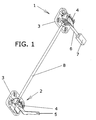
- the locking system for drawers has a rear subassembly (1), and a front subassembly (2), both interconnected with each other by means of a linking rod (8).
- the rear subassembly (1) is connected with the selective blocking device with anti-overturning effect (7) by means of a connecting bar (6).
- the front subassembly (2) is connected to the drawer lock by means of a locking bolt (5).
- Both subassemblies have individual latch supports (3) and their corresponding latches (4).
- figure 3 it is shown how on displacing the linking rod and displacing the lower end of the latch (4), the latter rotates about the hinge axle formed by the nipples which it has, housed in the cavities provided for this purpose in the support of the latch.
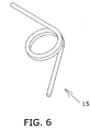
- the latch (4) of the rear subassembly (1) is secured to the latch support (3) together with two spring clips (15) (figure 6). These springs mean that when the displacement effected by the locking bolt (5) is removed, the latch (4) of the rear subassembly recovers its position displacing the linking rod (8), for which reason the connecting bar (6) with the selective blocking device (7) can move upward, allowing the opening of the drawer desired.
- the latch support piece (3) has a configuration with a flat base from which opposing planar elements emerge, having on its planar part a circular perforation (9) through which the linking rod (8) runs.
- it has a semicircular recess in the rear part of the base of the support piece (1), continuing through some opposing perforations (10) made in the base of the emerging elements, through which runs the bar (6) connecting with the selective blocking device (7) with anti-overturning effect of the rear subassembly (1).
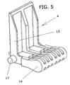
- Figure 5 shows the form which the latches (4) have, having nipples (12) arranged on the sides of one end and which when engaged in the perforations (11) of the support (3) allow the hinging of said end, having also a projecting rim (13) perpendicular to the body of the latch, on which rim the locking bolt (5) acts on the latch of the front subassembly (2), whilst the projection (14) is that which is displaced by the linking rod (8) and impedes the upward movement of the connecting bar (6) of the selective blocking device (7).
Landscapes
- Drawers Of Furniture (AREA)
Priority Applications (1)
| Application Number | Priority Date | Filing Date | Title |
|---|---|---|---|
| EP04381006A EP1580368A1 (de) | 2004-03-10 | 2004-03-10 | Schubladensperrsystem mit Umkippschutzvorrichtung |
Applications Claiming Priority (1)
| Application Number | Priority Date | Filing Date | Title |
|---|---|---|---|
| EP04381006A EP1580368A1 (de) | 2004-03-10 | 2004-03-10 | Schubladensperrsystem mit Umkippschutzvorrichtung |
Publications (1)
| Publication Number | Publication Date |
|---|---|
| EP1580368A1 true EP1580368A1 (de) | 2005-09-28 |
Family
ID=34854738
Family Applications (1)
| Application Number | Title | Priority Date | Filing Date |
|---|---|---|---|
| EP04381006A Withdrawn EP1580368A1 (de) | 2004-03-10 | 2004-03-10 | Schubladensperrsystem mit Umkippschutzvorrichtung |
Country Status (1)
| Country | Link |
|---|---|
| EP (1) | EP1580368A1 (de) |
Cited By (1)
| Publication number | Priority date | Publication date | Assignee | Title |
|---|---|---|---|---|
| CN107048766A (zh) * | 2017-03-27 | 2017-08-18 | 梧州理想科技有限公司 | 一种储物柜结构 |
Citations (5)
| Publication number | Priority date | Publication date | Assignee | Title |
|---|---|---|---|---|
| US4240685A (en) | 1979-02-05 | 1980-12-23 | Gf Business Equipment, Inc. | File lock and interlock |
| GB2220026A (en) | 1988-06-24 | 1989-12-28 | Rolls Royce Plc | Safety mechanism for cabinets |
| US4993784A (en) * | 1988-12-07 | 1991-02-19 | Engineered Security Products Corporation | Locking device |
| DE29824601U1 (de) * | 1998-04-09 | 2001-09-20 | Ojmar, S.A., Eibar, Guipúzcoa | Sperrvorrichtung für Schubladen in Möbeln |
| EP1340874A1 (de) * | 2002-02-27 | 2003-09-03 | Industrias Ragi, S.A. | Selektive Sperrvorrichtung für Schubladen mit Umkippschutz |
-
2004
- 2004-03-10 EP EP04381006A patent/EP1580368A1/de not_active Withdrawn
Patent Citations (5)
| Publication number | Priority date | Publication date | Assignee | Title |
|---|---|---|---|---|
| US4240685A (en) | 1979-02-05 | 1980-12-23 | Gf Business Equipment, Inc. | File lock and interlock |
| GB2220026A (en) | 1988-06-24 | 1989-12-28 | Rolls Royce Plc | Safety mechanism for cabinets |
| US4993784A (en) * | 1988-12-07 | 1991-02-19 | Engineered Security Products Corporation | Locking device |
| DE29824601U1 (de) * | 1998-04-09 | 2001-09-20 | Ojmar, S.A., Eibar, Guipúzcoa | Sperrvorrichtung für Schubladen in Möbeln |
| EP1340874A1 (de) * | 2002-02-27 | 2003-09-03 | Industrias Ragi, S.A. | Selektive Sperrvorrichtung für Schubladen mit Umkippschutz |
Cited By (1)
| Publication number | Priority date | Publication date | Assignee | Title |
|---|---|---|---|---|
| CN107048766A (zh) * | 2017-03-27 | 2017-08-18 | 梧州理想科技有限公司 | 一种储物柜结构 |
Similar Documents
| Publication | Publication Date | Title |
|---|---|---|
| US4811518A (en) | Door | |
| US4133271A (en) | Folding table with locking hinge | |
| EP3322269B1 (de) | Klammervorrichtung und gleitschienenanordnung damit | |
| RU2566480C2 (ru) | Крепежное устройство для закрепления лицевой панели на выдвижном ящике | |
| TWI629027B (zh) | 用於滑軌總成的同步系統 | |
| US7104619B2 (en) | Anti-tip interlocking linkage mechanism for vertical cabinets | |
| US7144050B2 (en) | Fire-blocking door lock structure | |
| JP5841127B2 (ja) | 垂直ケーブルマネージャドア | |
| JP2008507413A (ja) | モジュール式保管庫組立て品 | |
| TWI600392B (zh) | 托架裝置 | |
| CN107427126B (zh) | 抽屉侧壁 | |
| JP4251498B2 (ja) | 蓋体装置 | |
| CN107675996A (zh) | 一种防盗存储装置 | |
| EP3974256B1 (de) | Bidirektionale öffnungs- /schliessvorrichtung sowie armlehnenbox und fahrzeug | |
| JP2005192793A (ja) | 遊技機 | |
| JP3962840B2 (ja) | ロックピン係合位置調整機構 | |
| EP1340874B1 (de) | Selektive Sperrvorrichtung für Schubladen mit Umkippschutz | |
| JP3889288B2 (ja) | ブラインド用ブラケット | |
| CN223860408U (zh) | 斜翻桌面的午休课桌 | |
| JP5036529B2 (ja) | 可動棚装置 | |
| JP3140179U (ja) | 引き出しのインターロック装置 | |
| KR102168276B1 (ko) | 안전 도어장치를 갖는 위험물 보관함 | |
| JP3699857B2 (ja) | ラッチ | |
| JP2004243978A (ja) | 自動車の荷物収納構造 | |
| KR101229253B1 (ko) | 전자도어록 타입 캐비넷 도어 개폐 장치 |
Legal Events
| Date | Code | Title | Description |
|---|---|---|---|
| PUAI | Public reference made under article 153(3) epc to a published international application that has entered the european phase |
Free format text: ORIGINAL CODE: 0009012 |
|
| AK | Designated contracting states |
Kind code of ref document: A1 Designated state(s): AT BE BG CH CY CZ DE DK EE ES FI FR GB GR HU IE IT LI LU MC NL PL PT RO SE SI SK TR |
|
| AX | Request for extension of the european patent |
Extension state: AL LT LV MK |
|
| 17P | Request for examination filed |
Effective date: 20051110 |
|
| AKX | Designation fees paid |
Designated state(s): AT BE BG CH CY CZ DE DK EE ES FI FR GB GR HU IE IT LI LU MC NL PL PT RO SE SI SK TR |
|
| 17Q | First examination report despatched |
Effective date: 20080826 |
|
| STAA | Information on the status of an ep patent application or granted ep patent |
Free format text: STATUS: THE APPLICATION IS DEEMED TO BE WITHDRAWN |
|
| 18D | Application deemed to be withdrawn |
Effective date: 20091001 |