EP1580341B1 - Élément de liaison pour une construction de profilés et construction de profilés - Google Patents
Élément de liaison pour une construction de profilés et construction de profilés Download PDFInfo
- Publication number
- EP1580341B1 EP1580341B1 EP05004615A EP05004615A EP1580341B1 EP 1580341 B1 EP1580341 B1 EP 1580341B1 EP 05004615 A EP05004615 A EP 05004615A EP 05004615 A EP05004615 A EP 05004615A EP 1580341 B1 EP1580341 B1 EP 1580341B1
- Authority
- EP
- European Patent Office
- Prior art keywords
- longitudinal groove
- profile
- connecting element
- leg
- width
- Prior art date
- Legal status (The legal status is an assumption and is not a legal conclusion. Google has not performed a legal analysis and makes no representation as to the accuracy of the status listed.)
- Active
Links
- 238000010276 construction Methods 0.000 title claims abstract description 29
- 238000003780 insertion Methods 0.000 description 6
- 230000037431 insertion Effects 0.000 description 6
- 150000001875 compounds Chemical class 0.000 description 3
- 230000001154 acute effect Effects 0.000 description 2
- 238000005516 engineering process Methods 0.000 description 2
- 230000000284 resting effect Effects 0.000 description 2
- 238000006073 displacement reaction Methods 0.000 description 1
- 230000002349 favourable effect Effects 0.000 description 1
- 238000005192 partition Methods 0.000 description 1
- 230000002787 reinforcement Effects 0.000 description 1
- 238000009420 retrofitting Methods 0.000 description 1
Images

Classifications
-
- F—MECHANICAL ENGINEERING; LIGHTING; HEATING; WEAPONS; BLASTING
- F16—ENGINEERING ELEMENTS AND UNITS; GENERAL MEASURES FOR PRODUCING AND MAINTAINING EFFECTIVE FUNCTIONING OF MACHINES OR INSTALLATIONS; THERMAL INSULATION IN GENERAL
- F16B—DEVICES FOR FASTENING OR SECURING CONSTRUCTIONAL ELEMENTS OR MACHINE PARTS TOGETHER, e.g. NAILS, BOLTS, CIRCLIPS, CLAMPS, CLIPS OR WEDGES; JOINTS OR JOINTING
- F16B7/00—Connections of rods or tubes, e.g. of non-circular section, mutually, including resilient connections
- F16B7/18—Connections of rods or tubes, e.g. of non-circular section, mutually, including resilient connections using screw-thread elements
- F16B7/187—Connections of rods or tubes, e.g. of non-circular section, mutually, including resilient connections using screw-thread elements with sliding nuts or other additional connecting members for joining profiles provided with grooves or channels
-
- F—MECHANICAL ENGINEERING; LIGHTING; HEATING; WEAPONS; BLASTING
- F16—ENGINEERING ELEMENTS AND UNITS; GENERAL MEASURES FOR PRODUCING AND MAINTAINING EFFECTIVE FUNCTIONING OF MACHINES OR INSTALLATIONS; THERMAL INSULATION IN GENERAL
- F16B—DEVICES FOR FASTENING OR SECURING CONSTRUCTIONAL ELEMENTS OR MACHINE PARTS TOGETHER, e.g. NAILS, BOLTS, CIRCLIPS, CLAMPS, CLIPS OR WEDGES; JOINTS OR JOINTING
- F16B37/00—Nuts or like thread-engaging members
- F16B37/04—Devices for fastening nuts to surfaces, e.g. sheets, plates
- F16B37/045—Devices for fastening nuts to surfaces, e.g. sheets, plates specially adapted for fastening in channels, e.g. sliding bolts, channel nuts
Definitions
- the invention relates to a profile construction with at least two profiled bars, each with at least one provided with an undercut longitudinal groove and at least one connecting element for releasably connecting the two profile bars.
- profile constructions are used for the production of frame-like racks, which are formed essentially by horizontally and vertically arranged profile bars, which are releasably connected together in the region of their vertices by means of connecting pieces.
- profile bars and connectors are used, so can hereby form a modular system, which allows to produce frame or shelves of different embodiments with relatively little technical effort.
- the profile bars each having at least one provided with an undercut longitudinal groove, wherein at least in a part of the profile bars in the region of its front ends a parallel to the longitudinal groove extending thread for receiving a fastening screw is required.
- a T-shaped retaining piece is locked on the front side of the first profiled bar, which engages in the longitudinal groove of the second profiled bar to be connected to the first profiled bar so that it engages behind the webs of the undercut of the longitudinal groove.
- the retaining piece is further provided with an internal thread for receiving a second screw, which is supported with its one end against the fastening screw such that the retaining piece is pressed against the webs of the undercut, that the profile bars are firmly connected to each other via the retaining piece.
- the DE-101 19 548 shows a profile construction with mutually spaced vertical profile bars, which offers the opportunity to use at any point the same subsequently horizontal profile bars without having to disassemble the profile structure at least partially.
- two respective two-part fastening means are provided for connecting the two vertical profile bars with the respective ends of the horizontal profile bar, of which each one half of the Be-fest Trentsstoff is attached to one longitudinal side of the vertically arranged profile bars, while the respective other half of the two fasteners the end faces of the horizontally arranged profile bar is attached.
- the connection of the respective half of the fastening means with the profiled bars in this case takes place in each case by means of a groove to be introduced into the longitudinal groove of the profiled bars together with a corresponding fastening screw.
- the shows DE-U-9304726 a scaffolding construction provided in particular for the rack construction, which comprises profiled bars provided with undercut longitudinal grooves, which are connected to one another by means of angle connectors and corresponding screw connections.
- the angle connectors have in the side view the shape of a right-angled isosceles triangle, on whose leg outer surfaces web projections are formed, the width of which corresponds to the width of the groove openings.
- a through hole for a fastening screw is provided on this, which cooperates with a to be arranged within the longitudinal groove of the profile bar nut, which is inserted from one of the front ends of the profile bar in the groove.
- an additional profile bar for example, an additional support or an additional horizontal reinforcement to be introduced into an existing profile construction, for example in a rack system.
- the invention is therefore based on the object to provide a compound for angularly arranged profile bars of a profile construction, on the one hand requires neither a central profile bore nor a mechanical processing of the profile bars, and on the other hand, the possibility of retrofitting a profile bar between two at a distance arranged profile bars provides a profile construction, while ensuring that the outer surfaces of the interconnected profile bars are free of connecting parts, and the latter are not visible on the outer surfaces of the profile construction.
- By screwing the fastening screw in the internal thread of the fastener of this leg of the connecting element is mounted in the profile bar, with the top of the fastener on the underside of the undercut limiting webs of the profile bar and the mounting screw is supported on the bottom of the longitudinal groove.
- the first leg of the connecting element and the first fastening means on the longitudinal side of the profiled bar between the webs and introduced through the longitudinal groove in the region of the undercut of the longitudinal groove and positioned to each other become. Since the width of the fastener is wider than the width of the longitudinal groove in the region of the webs, the fastener is led upstanding by a certain amount between the webs and thereby brought slightly into an inclined position, so that it rests flat on the bottom of the longitudinal groove and from there on pushed the leg of the connecting element and can be positioned on this.
- the first leg of the connecting element is fastened in the same way in the profile bar, wherein the upper side of the fastening means is also supported on the underside of the undercut limiting webs of the profiled bar and the fastening screw at the bottom of the longitudinal groove.
- both the opposite of the end face of the horizontal profiled bar projecting portion of the first leg and the second leg of the connecting element and the second leg of the connecting element associated second fastening means between the webs of the first vertically arranged profile bar in the region of the undercut of the longitudinal groove thereof are introduced.
- the fastening means is pushed above the leg high through the longitudinal groove into the profile bar and thereby rotated slightly about its longitudinal axis, so that it comes to rest between the legs of the connecting element and the inside of the webs on the leg.
- tightening the fixing screw this is supported on the inside of the leg, whereby it comes with its outside at the bottom of the longitudinal groove and the fastening means on the inside of the webs to the plant.
- the compound thus formed between the horizontal and the vertical profile bar is characterized by the one hand on any of the outer sides of the profile bars, a connecting element is visible, and even the corner region of the respective profile bars is completely free of parts of the compound.
- the length of the profile bar to be arranged horizontally corresponds to the clear distance of the two vertically arranged profile bars, and the still free end face of the horizontal profile bar rests against the outside of the second vertical profile bar, which was for connecting the second end of the horizontal profile bar with the second vertically arranged profiled bar serving second connecting element introduced either simultaneously with the first connecting element in the longitudinal groove of the horizontal profile bar or is now in the position of the first connecting element mirror image position at any point of the longitudinal groove of the horizontal profile bar from above through this to insert into the horizontal profile bar.
- the two fastening means of each connecting element are each formed by a square nut whose key width corresponds substantially to the width of the region of the undercut of the longitudinal groove.
- the square nuts have a flattened dome on their underside, they can be relatively easily positioned to the respective leg of the connecting elements.
- a handling technology favorable design of the connecting elements can be achieved in that one of the fastening means and the first leg of the connecting element are integrally formed.
- a further facilitation of the positioning of the respective square nut to the respective leg of the connecting element is achieved when the free end of the corresponding leg has a bevel serving as a ramp for the square nut bevel.
- An increase in the load capacity of the connection between the respective profile bar and the respective second leg of the connecting element can be achieved in that the outer surface of the respective second leg of the connecting element is provided with a toothing, so that the holding force of friction between profile bar and connecting element by the additional positive engagement is increased.
- first leg of the connecting element and the fastening means are integrally formed, it is advantageous for determining the relative position between the connecting element and the profile bar, when the first leg has two abutment surfaces coming to rest on the outside of the second profile bar, wherein the stop surfaces with a toothing can be provided.
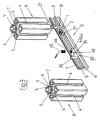
- a first embodiment of a provided for use in a profile construction for connecting arranged at an angle to each other profile bars connecting element 1 is shown, which is formed substantially angularly, and -based on the prevailing operating position- a first, substantially horizontally directed leg 2 and a second, substantially vertically directed leg 3, which are fixedly connected to each other and have the same width.
- the profile bars to be joined together are of known type and may have a rectangular or square or any other cross-sectional shape. Common to all profile bars is that they have on one or more of their outer sides one or more parallel to their longitudinal direction extending grooves which extend over its entire length and are therefore referred to as "longitudinal grooves 4".
- the width of the two legs 2,3 of the connecting element 1 substantially corresponds to the width of the longitudinal groove 4 of the profiled bars and is chosen so that the connecting element 1 can slide in the longitudinal grooves 4 of the profiled bars almost free of play.
- Each of the two legs 2,3 is assigned a serving as a fastener square nut 12,13, each of which is provided with an unspecified internal thread.
- the square nuts 12,13 have a square shape whose key width corresponds substantially to the width of the undercut portion 5 of the longitudinal grooves 4, so that they are displaceable within the undercut region 5 of the longitudinal grooves 4.
- the square nuts 12, 13 are each provided with a dome-shaped dome 14.
- Both fastening screws 15,16 are formed as Allen screws and can each have a kind of center point 17, which are supported on the mutually facing surfaces of the two legs 2,3.
- a graining 18 is provided on each of the two legs 2, 3.
- the thickness of the two square nuts 12, 13 is dimensioned such that they can be inserted high through the longitudinal grooves 4 into the undercut region 5 thereof.
- the thickness of the square nuts 12, 13 and the thickness of the legs 2.3 is coordinated so that the connecting elements 1 with resting on their legs 2.3, or adjacent thereto square nuts 12, 13 within the undercut portions 5 of the longitudinal grooves 4 relatively easy to move.
- a toothing 20 may be provided on the outer surface 19 of the vertical leg 3.
- a toothing 20 may be provided on the outer surface 19 of the vertical leg 3.
- the free ends of the two legs 2,3 are each provided with an inclined surface 21 serving as a drainage slope.
- Fig. 2 a second embodiment of a provided for use in a profile construction for connecting mutually spaced profile bars connecting element 31 is shown, the is also formed substantially angularly, and-based on the predominantly occurring position of use, a first, substantially horizontally directed leg 32 and a second, substantially vertically directed legs 33 which are fixedly connected to each other.
- the width of the vertical leg 33 of the connecting element 31 substantially corresponds to the width of the longitudinal groove 4 of the profile bars 8, 9 and 11 and is also chosen so that the leg 33 of the connecting element 31 in the longitudinal grooves 4 of the profile bars 8.9 can slide almost without play .
- the leg 33 is assigned a serving as a fastener square nut 34, which is provided with an unspecified internal thread.
- the square nut 34 also has a square shape, the key width of which corresponds substantially to the width of the undercut region 5 of the longitudinal grooves 4, so that it is displaceable within the undercut region 5 of the longitudinal grooves 4.
- the square nut 34 On its underside, the square nut 34 is provided with a dome-shaped dome 35. With the square nut 34, a fastening screw 36 cooperates.
- This is designed as a hexagon socket screw and may have a kind of center point 37, which is supported on the leg 32 facing surface of the leg 33.
- a graining 38 is provided on the leg 33.
- the thickness of the square nut 34 is also sized so that it can be introduced high through the longitudinal grooves 4 in the undercut area 5 of the same.
- the thickness of the square nut 34 and the thickness of the leg 33 are tuned so that the Kirslement 31 can move relative to their leg 33 abutting square nut 34 within the undercut portions 5 of the longitudinal grooves 4 relatively easily.
- a toothing 40 may be provided on the outer surface 39 of the vertical leg 33 to increase the carrying capacity of the frictional connection between the respective profile bar and the leg 33 of the connecting element 31. How out Fig. 2 can be seen, the free end of the leg 33 is provided with each serving as a slope inclined surface 41.
- the substantially horizontally directed leg 32 has in its connected to the leg 33 portion 42 the same width as the leg 33, so that also the area 42 of the leg 32 can move almost without play within the longitudinal grooves 4 of the profile bars.
- the horizontally directed leg 32 has a projection 43, which serves as a fastening means 44.
- the height of the fastener 44 is slightly less than the distance between the bottom 6 and the underside of the webs 7, so that the fastener 44 smoothly within the undercut portion 5 of Can move longitudinal grooves 4.
- the fastening means 44 is provided with an unspecified continuous internal thread, with which cooperates designed as a hexagon socket screw fastening screw 45, which may have a center point 46 on its underside. When screwing the fastening screw 45 into the internal thread of the fastening means 44, the fastening screw 45 is supported on the bottom 6 of the undercut region 5, whereby the upper side of the fastening means 44 frictionally rests against the underside of the webs 7.
- the fastening means 44 is provided at the two edge regions of its upper side with a toothing 47. Due to the different widths of the region 42 of the leg 32 and the fastening means 44, two vertical abutment surfaces 48 are formed on the leg 32, which come when inserting the connecting element 31 in the respective longitudinal groove 4 of the profile bars 8,9 on the outer surfaces to the plant.
- the stop surfaces 48 may be provided with a toothing 49.
- the fastening means 44 provided internal thread can be arranged at an acute angle to the leg 33, so that when screwing the fastening screw 45 into the internal thread an axial force acts on the leg 33 of the connecting element 31.
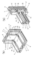
- Fig. 3 is a longitudinal section through a horizontally disposed section bar 11 is shown, which is to be used between two vertically arranged profile bars 8.9, which have a non-variable mutual distance and the end faces are not accessible. This is always the case when a cross member is subsequently to be installed in an existing frame or shelf. Furthermore, it is assumed that the length of the horizontally arranged profile bar 11 to be used corresponds to the clear distance between the two vertical profile bars 8, 9. In order to be able to simultaneously explain the modes of action of both embodiments described above, reference is made to Fig.
- the leg 2 of the connecting element 1 in the in Fig. 3 shown position together with the square nut 13 and inserted into this fastening screw 16 from the right end of the section bar 11 in the undercut area 5 of its longitudinal groove 4 inserted.
- the square nut 13 rests on the leg 2, wherein the top of the square nut 13 below the undercut region 5 of the longitudinal groove 4 limiting webs 7 is located.
- the latter can be tightened so far that the connecting element 1 within the profile bar 11 while still easy to move, but falling out is prevented.
- the profiled bar 11 is positioned between the two profiled bars 8,9 so that its longitudinal groove 4 is located exactly opposite the two vertically extending longitudinal grooves 4 of the profiled bars 8,9.
- the two connecting elements 1 and 31 are inserted and positioned with their respective vertical legs 3 and 33 in the two longitudinal grooves 4 of the profile bars 8.9.
- the stop surfaces 48 come to the outer sides of the profile bars 8,9 to the plant and form a limit to the depth of insertion of the connecting element 31 in the respective longitudinal groove 4 of the profile bars 8,9 wherein, when provided in the fastening means 44 internal thread at an acute angle to the vertical extends over the teeth 47, a tensile force applied to the profile bar.
- the square nuts 12,34 are inserted in an elevated position above the respective leg 3 and 33 in the respective longitudinal groove 4 and turned slightly in this insertion, so they within the undercut region 5 as in a guide channel to slide downwards and impinge on the respective inclined surface 21 or 41 of the leg 3 and 33 and reach between the inner sides of the legs 3 and 33 and the webs 7.
- the fastening screws 16 and 45 or 15 and 37 are tightened, so that the connection between the profile bar 11 and the profile bars 8.9 is completed at both ends.
- Fig. 4 a corner joint on a flat cross-section profiled bars, which is made using two juxtaposed fasteners.
- Fig. 5 shows a longitudinal section of a particularly viable corner joint, in which two connecting elements are arranged in mirror image one above the other.
Claims (17)
- Élément de liaison pour relier de façon amovible au moins deux tiges profilées disposées en angle l'une par rapport à l'autre à respectivement au moins une rainure longitudinale (4) pourvue d'une contre-dépouille (5) délimitée par un fond (6) et deux étais (7) s'étendant parallèlement à celui-ci, comportant deux bords (2, 3) disposés en angle l'un par rapport à l'autre avec respectivement un moyen de fixation (12, 13) chacun pouvant être fixés aux tiges profilées,
caractérisé en ce que :la largeur des deux bords (2,3) correspond pour l'essentiel à la largeur de la rainure longitudinale (4), dans sa zone non contre-dépouillée ;et les deux bords (2,3) pouvant être introduits au niveau du côté longitudinal de la tige profilée, entre les étais 7 et/ou la zone contre-dépouillée de la rainure longitudinale (4) de la tige profilée, dans sa zone contre-dépouillée (5) ;la largeur des moyens de fixation (12, 13) pourvus d'au moins un filetage intérieur correspondant pour l'essentiel à la largeur de la zone contre-dépouillée (5) de la rainure longitudinale (4) ;et l'épaisseur des écrous carrés (34) servant de moyens de fixation étant mesurée de telle sorte qu'ils peuvent, en étant à un niveau élevé au niveau du côté longitudinal de la tige profilée, être introduits dans la zone contre-dépouillée (5) de la rainure longitudinale (4) en passant à travers la rainure longitudinale (4) ;la largeur du moyen de fixation (12, 13) étant plus large que la largeur de la rainure longitudinale (4) dans la zone des étais (7), de sorte que le moyen de fixation est introduit, en étant à un niveau élevé, d'une quantité donnée entre les étais (7) et peut ainsi être amené dans une position légèrement inclinée, de sorte qu'il peut reposer à plat sur le fond de la rainure longitudinale (4) et peut être poussé par les bords supérieurs de l'élément de liaison et peut être positionné sur lui ;de sorte que les bords (2, 3) peuvent être fixés à l'intérieur de la zone (5) contre-dépouillée de la rainure longitudinale (4) au moyen des moyens de fixation (12, 13). - Élément de liaison selon la revendication 1, caractérisé en ce que les moyens de fixation (12, 13 ; 34, 44) sont formés respectivement par un écrou carré (12, 13 ; 34, 44) dont la largeur de clé correspond pour l'essentiel à la largeur de la zone de la contre-dépouille (5) de la rainure longitudinale (4).
- Élément de liaison selon la revendication 2, caractérisé en ce que chacun des écrous carrés (12, 13 ; 34, 44) comporte au niveau de son côté inférieur un bout bombé (14) de type calotte.
- Élément de liaison selon la revendication 1, caractérisé en ce qu'un des moyens de fixation (44) et son bord (32) sont réalisés d'un seul tenant.
- Élément de liaison selon la revendication 1, caractérisé en ce que l'extrémité libre du deuxième bord (3, 33) comporte une position inclinée (21, 41) servant de biais tournant.
- Élément de liaison selon la revendication 1, caractérisé en ce que la surface extérieure (19, 39) du deuxième bord (3, 33) est pourvue d'une denture (20, 40).
- Élément de liaison selon les revendications 1 et 4, caractérisé en ce que le premier bord (32) comporte deux surfaces de butée (48) venant reposer contre le côté extérieur de la deuxième tige profilée.
- Élément de liaison selon la revendication 7, caractérisé en ce que les surfaces de butée (48) sont pourvues d'une denture (49).
- Construction de profilés avec une liaison amovible d'au moins deux tiges profilées disposées en angle l'une par rapport à l'autre avec respectivement au moins une rainure longitudinale (4) pourvue d'une contre-dépouille (5) délimitée par un fond (6) et deux étais (7) s'étendant parallèlement à lui, comportant un élément de liaison pourvu de deux bords (2, 3) disposés en angle l'un par rapport à l'autre avec respectivement un moyen de fixation (12, 13) pouvant être fixé aux tiges profilées ;
caractérisée en ce que :la largeur des deux bords (2,3) correspond pour l'essentiel à la largeur de la rainure longitudinale (4) dans sa zone non contre-dépouillée ;et les deux bords (2, 3) pouvant être introduits dans sa zone contre-dépouillée (5) au niveau du côté longitudinal de la tige profilée, entre les étais 7 et/ou la zone non contre-dépouillée de la rainure longitudinale (4) de la tige profilée ;la largeur des moyens de fixation (12, 13) pourvue d'au moins un filetage intérieur correspondant pour l'essentiel à la largeur de la zone contre-dépouillée (5) de la rainure longitudinale (4) ;et l'épaisseur des écrous carrés (34) servant de moyens de fixation étant mesurée de telle sorte que celle-ci peut être introduite, en étant à un niveau élevé au niveau du côté longitudinal de la tige profilée, à travers la rainure longitudinale (4), dans la zone contre-dépouillée (5) de la rainure longitudinale (4) ;la largeur du moyen de fixation (12, 13) étant plus large que la largeur de la rainure longitudinale (4) dans la zone des étais (7), de sorte que le moyen de fixation est introduit d'une quantité donnée entre les étais (7) en étant à un niveau élevé et peut ainsi être amené légèrement dans une position inclinée, de façon à pouvoir reposer à plat sur le fond de la rainure longitudinale (4) et de là être positionné au-dessus du bord de l'élément de liaison et sur lui ;de sorte que les bords (2, 3) peuvent être fixés à l'intérieur de la zone contre-dépouillée (5) de la rainure longitudinale (4) au moyen des moyens de fixation (12, 13). - Construction de profilés selon la revendication 9, caractérisée en ce que les moyens de fixation (12, 13 ; 34, 44) sont formés par respectivement un écrou carré (12, 13 ; 34, 44) dont la largeur de clé correspond pour l'essentiel à la largeur de la zone de la contre-dépouille (5) de la rainure longitudinale (4).
- Construction de profilés selon la revendication 9, caractérisée en ce qu'un des moyens de fixation (44) et son bord (32) sont réalisés d'un seul tenant.
- Construction de profilés selon la revendication 11, caractérisée en ce que l'écrou carré (34) comporte au niveau de son côté inférieur un bout bombé (14) de type calotte.
- Construction de profilés selon la revendication 9, caractérisée en ce que l'extrémité libre du deuxième bord (3, 33) comporte une surface inclinée (21, 41) servant de biais tournant.
- Construction de profilés selon la revendication 9, caractérisée en ce que la surface extérieure (19, 39) du deuxième bord (3, 33) est pourvue d'une denture (20, 40).
- Construction de profilés selon la revendication 9, caractérisée en ce que le premier bord (32) comporte deux surfaces de butée (48) venant reposer contre le côté extérieur de la deuxième tige profilée.
- Construction de profilés selon la revendication 15, caractérisée en ce que les surfaces de butée (48) sont pourvues d'une denture (49).
- Construction de profilés selon la revendication 9, caractérisée en ce que la surface extérieure (39) du deuxième bord (33) est pourvue d'une denture (40).
Applications Claiming Priority (2)
| Application Number | Priority Date | Filing Date | Title |
|---|---|---|---|
| DE102004013631A DE102004013631A1 (de) | 2004-03-13 | 2004-03-13 | Profilkonstruktion |
| DE102004013631 | 2004-03-13 |
Publications (3)
| Publication Number | Publication Date |
|---|---|
| EP1580341A2 EP1580341A2 (fr) | 2005-09-28 |
| EP1580341A3 EP1580341A3 (fr) | 2006-10-18 |
| EP1580341B1 true EP1580341B1 (fr) | 2010-04-28 |
Family
ID=34853990
Family Applications (1)
| Application Number | Title | Priority Date | Filing Date |
|---|---|---|---|
| EP05004615A Active EP1580341B1 (fr) | 2004-03-13 | 2005-03-03 | Élément de liaison pour une construction de profilés et construction de profilés |
Country Status (4)
| Country | Link |
|---|---|
| EP (1) | EP1580341B1 (fr) |
| AT (1) | ATE466146T1 (fr) |
| DE (2) | DE102004013631A1 (fr) |
| ES (1) | ES2345050T3 (fr) |
Cited By (1)
| Publication number | Priority date | Publication date | Assignee | Title |
|---|---|---|---|---|
| DE102014018920A1 (de) | 2014-12-22 | 2016-06-23 | innoTech Beteiligungsgesellschaft für innovative Technologien mbH | Verbindereinrichtung für Profilstäbe |
Families Citing this family (3)
| Publication number | Priority date | Publication date | Assignee | Title |
|---|---|---|---|---|
| DE102007009667B4 (de) | 2007-02-26 | 2011-04-21 | Minitec Maschinenbau Gmbh & Co. Kg | Profilkonstruktion |
| AT508175B1 (de) * | 2009-05-06 | 2012-09-15 | Baumann Holding 1886 Gmbh | Verbindung und standsäule |
| DE102020134735A1 (de) | 2020-12-22 | 2022-06-23 | Carl-Peter Schoene | Baukastensystem zur Herstellung eines Lager- und Transportelementes, Verwendung eines Baukastensystems sowie Lager- und Transportelement |
Family Cites Families (8)
| Publication number | Priority date | Publication date | Assignee | Title |
|---|---|---|---|---|
| US2996159A (en) * | 1958-06-02 | 1961-08-15 | Ralph T Casebolt | Miter joint |
| FR2119246A5 (fr) * | 1970-12-24 | 1972-08-04 | Elmaduc | |
| FR2330898A1 (fr) * | 1975-11-04 | 1977-06-03 | Udave Jean | Systeme de liaison pour profiles metalliques |
| DE8326978U1 (de) * | 1983-09-15 | 1984-01-12 | Schweizerische Aluminium AG, 3965 Chippis | Gerippe fuer einen wagenkasten |
| DE4142273C2 (de) * | 1991-12-20 | 1996-04-18 | Bosch Gmbh Robert | Vorrichtung zum lösbaren Verbinden von zwei in einer Ebene senkrecht aufeinanderstehenden Strebenprofilen |
| DE4210456C2 (de) * | 1992-03-30 | 1995-05-11 | Helmuth Kahl | Querverbindung für Profilstäbe mittels Zuggliedern |
| DE9304726U1 (fr) * | 1993-03-27 | 1993-07-22 | Jou, Ce Cei, Chunghua, Tw | |
| DE10119548A1 (de) | 2001-04-19 | 2002-10-24 | Minitec Maschb Gmbh & Co Kg | Strebeneinrichtung |
-
2004
- 2004-03-13 DE DE102004013631A patent/DE102004013631A1/de not_active Withdrawn
-
2005
- 2005-03-03 AT AT05004615T patent/ATE466146T1/de active
- 2005-03-03 EP EP05004615A patent/EP1580341B1/fr active Active
- 2005-03-03 ES ES05004615T patent/ES2345050T3/es active Active
- 2005-03-03 DE DE502005009477T patent/DE502005009477D1/de active Active
Cited By (2)
| Publication number | Priority date | Publication date | Assignee | Title |
|---|---|---|---|---|
| DE102014018920A1 (de) | 2014-12-22 | 2016-06-23 | innoTech Beteiligungsgesellschaft für innovative Technologien mbH | Verbindereinrichtung für Profilstäbe |
| DE102014018920B4 (de) | 2014-12-22 | 2018-12-27 | innoTech Beteiligungsgesellschaft für innovative Technologien mbH | Verbindereinrichtung für Profilstäbe |
Also Published As
| Publication number | Publication date |
|---|---|
| DE502005009477D1 (de) | 2010-06-10 |
| EP1580341A3 (fr) | 2006-10-18 |
| DE102004013631A1 (de) | 2005-09-29 |
| ES2345050T3 (es) | 2010-09-14 |
| ATE466146T1 (de) | 2010-05-15 |
| EP1580341A2 (fr) | 2005-09-28 |
Similar Documents
| Publication | Publication Date | Title |
|---|---|---|
| EP0310546B1 (fr) | Disposition variable de cadres de montage | |
| WO2012113549A1 (fr) | Dispositif d'assemblage d'angle pour profilés creux | |
| DE3636639A1 (de) | Bauelement-system | |
| DE3224899A1 (de) | Verbindungselement fuer platten | |
| EP1580341B1 (fr) | Élément de liaison pour une construction de profilés et construction de profilés | |
| WO2006092156A1 (fr) | Element paroi | |
| EP1002166B1 (fr) | Cloison, notamment pour stands d'expositions | |
| DE2507721A1 (de) | Mosaikschaltwand | |
| DE3928486C2 (de) | Bauteil für Rahmen- und/oder Tragkonstruktionen | |
| EP0773615B1 (fr) | Armoire de commutation pour installation électrique | |
| EP2260742A1 (fr) | Système de meuble | |
| DE3231114A1 (de) | Verbindungssystem | |
| DE3517568A1 (de) | Regal mit einstellbaren fachboeden | |
| EP2017483B1 (fr) | Structure de profilé | |
| DE10351395A1 (de) | Verbindungselement unter Verwendung eines solchen Verbindungselements realisierte Montageeinheit | |
| EP0307628B2 (fr) | Structure réticulée avec barres et noeuds | |
| DE19824063A1 (de) | I-förmiger Träger für Gebäudekonstruktionen | |
| DE102006059750A1 (de) | Möbelverkettungselement, Möbel und Montageverfahren | |
| DE102008003354B4 (de) | Kreuzungsbereich einer Rillenschienenkreuzung | |
| DE19845138C1 (de) | Spreizkloben mit Verbindungssicherungen | |
| DE19620709C5 (de) | Möbelfußsystem | |
| DE19507263C2 (de) | Tragsystem mit Tragprofilen | |
| DE19508949A1 (de) | Bausatz für ein Tragsystem | |
| DE4444413A1 (de) | Bausatz für Skelettkonstrukionen wie Regale, Rahmen, Ständer u. dgl. | |
| EP0528255A1 (fr) | Jeu de construction pour cadres comprenant des profilés creux et des connecteurs de coins |
Legal Events
| Date | Code | Title | Description |
|---|---|---|---|
| PUAI | Public reference made under article 153(3) epc to a published international application that has entered the european phase |
Free format text: ORIGINAL CODE: 0009012 |
|
| AK | Designated contracting states |
Kind code of ref document: A2 Designated state(s): AT BE BG CH CY CZ DE DK EE ES FI FR GB GR HU IE IS IT LI LT LU MC NL PL PT RO SE SI SK TR |
|
| AX | Request for extension of the european patent |
Extension state: AL BA HR LV MK YU |
|
| RIN1 | Information on inventor provided before grant (corrected) |
Inventor name: NEUMUELLER, AXEL Inventor name: RISCH, KARL-HEINZ |
|
| PUAL | Search report despatched |
Free format text: ORIGINAL CODE: 0009013 |
|
| AK | Designated contracting states |
Kind code of ref document: A3 Designated state(s): AT BE BG CH CY CZ DE DK EE ES FI FR GB GR HU IE IS IT LI LT LU MC NL PL PT RO SE SI SK TR |
|
| AX | Request for extension of the european patent |
Extension state: AL BA HR LV MK YU |
|
| RIC1 | Information provided on ipc code assigned before grant |
Ipc: F16B 7/04 20060101ALI20060914BHEP Ipc: F16B 7/18 20060101ALI20060914BHEP Ipc: E04B 2/76 20060101AFI20050615BHEP |
|
| 17P | Request for examination filed |
Effective date: 20061221 |
|
| 17Q | First examination report despatched |
Effective date: 20070330 |
|
| AKX | Designation fees paid |
Designated state(s): AT BE BG CH CY CZ DE DK EE ES FI FR GB GR HU IE IS IT LI LT LU MC NL PL PT RO SE SI SK TR |
|
| GRAP | Despatch of communication of intention to grant a patent |
Free format text: ORIGINAL CODE: EPIDOSNIGR1 |
|
| RTI1 | Title (correction) |
Free format text: CONNECTING ELEMENT FOR A PROFILE CONSTRUCTION AND PROFILE CONSTRUCTION |
|
| GRAS | Grant fee paid |
Free format text: ORIGINAL CODE: EPIDOSNIGR3 |
|
| GRAA | (expected) grant |
Free format text: ORIGINAL CODE: 0009210 |
|
| AK | Designated contracting states |
Kind code of ref document: B1 Designated state(s): AT BE BG CH CY CZ DE DK EE ES FI FR GB GR HU IE IS IT LI LT LU MC NL PL PT RO SE SI SK TR |
|
| REG | Reference to a national code |
Ref country code: GB Ref legal event code: FG4D Free format text: NOT ENGLISH |
|
| REG | Reference to a national code |
Ref country code: CH Ref legal event code: EP |
|
| REG | Reference to a national code |
Ref country code: IE Ref legal event code: FG4D Free format text: LANGUAGE OF EP DOCUMENT: GERMAN |
|
| REF | Corresponds to: |
Ref document number: 502005009477 Country of ref document: DE Date of ref document: 20100610 Kind code of ref document: P |
|
| REG | Reference to a national code |
Ref country code: NL Ref legal event code: VDEP Effective date: 20100428 |
|
| REG | Reference to a national code |
Ref country code: ES Ref legal event code: FG2A Ref document number: 2345050 Country of ref document: ES Kind code of ref document: T3 |
|
| LTIE | Lt: invalidation of european patent or patent extension |
Effective date: 20100428 |
|
| PG25 | Lapsed in a contracting state [announced via postgrant information from national office to epo] |
Ref country code: LT Free format text: LAPSE BECAUSE OF FAILURE TO SUBMIT A TRANSLATION OF THE DESCRIPTION OR TO PAY THE FEE WITHIN THE PRESCRIBED TIME-LIMIT Effective date: 20100428 Ref country code: SE Free format text: LAPSE BECAUSE OF FAILURE TO SUBMIT A TRANSLATION OF THE DESCRIPTION OR TO PAY THE FEE WITHIN THE PRESCRIBED TIME-LIMIT Effective date: 20100428 Ref country code: NL Free format text: LAPSE BECAUSE OF FAILURE TO SUBMIT A TRANSLATION OF THE DESCRIPTION OR TO PAY THE FEE WITHIN THE PRESCRIBED TIME-LIMIT Effective date: 20100428 |
|
| REG | Reference to a national code |
Ref country code: IE Ref legal event code: FD4D |
|
| PG25 | Lapsed in a contracting state [announced via postgrant information from national office to epo] |
Ref country code: FI Free format text: LAPSE BECAUSE OF FAILURE TO SUBMIT A TRANSLATION OF THE DESCRIPTION OR TO PAY THE FEE WITHIN THE PRESCRIBED TIME-LIMIT Effective date: 20100428 Ref country code: SI Free format text: LAPSE BECAUSE OF FAILURE TO SUBMIT A TRANSLATION OF THE DESCRIPTION OR TO PAY THE FEE WITHIN THE PRESCRIBED TIME-LIMIT Effective date: 20100428 Ref country code: IS Free format text: LAPSE BECAUSE OF FAILURE TO SUBMIT A TRANSLATION OF THE DESCRIPTION OR TO PAY THE FEE WITHIN THE PRESCRIBED TIME-LIMIT Effective date: 20100828 |
|
| PG25 | Lapsed in a contracting state [announced via postgrant information from national office to epo] |
Ref country code: GR Free format text: LAPSE BECAUSE OF FAILURE TO SUBMIT A TRANSLATION OF THE DESCRIPTION OR TO PAY THE FEE WITHIN THE PRESCRIBED TIME-LIMIT Effective date: 20100729 Ref country code: CY Free format text: LAPSE BECAUSE OF FAILURE TO SUBMIT A TRANSLATION OF THE DESCRIPTION OR TO PAY THE FEE WITHIN THE PRESCRIBED TIME-LIMIT Effective date: 20100428 Ref country code: PL Free format text: LAPSE BECAUSE OF FAILURE TO SUBMIT A TRANSLATION OF THE DESCRIPTION OR TO PAY THE FEE WITHIN THE PRESCRIBED TIME-LIMIT Effective date: 20100428 |
|
| PG25 | Lapsed in a contracting state [announced via postgrant information from national office to epo] |
Ref country code: IE Free format text: LAPSE BECAUSE OF FAILURE TO SUBMIT A TRANSLATION OF THE DESCRIPTION OR TO PAY THE FEE WITHIN THE PRESCRIBED TIME-LIMIT Effective date: 20100428 Ref country code: EE Free format text: LAPSE BECAUSE OF FAILURE TO SUBMIT A TRANSLATION OF THE DESCRIPTION OR TO PAY THE FEE WITHIN THE PRESCRIBED TIME-LIMIT Effective date: 20100428 Ref country code: DK Free format text: LAPSE BECAUSE OF FAILURE TO SUBMIT A TRANSLATION OF THE DESCRIPTION OR TO PAY THE FEE WITHIN THE PRESCRIBED TIME-LIMIT Effective date: 20100428 Ref country code: PT Free format text: LAPSE BECAUSE OF FAILURE TO SUBMIT A TRANSLATION OF THE DESCRIPTION OR TO PAY THE FEE WITHIN THE PRESCRIBED TIME-LIMIT Effective date: 20100830 |
|
| PG25 | Lapsed in a contracting state [announced via postgrant information from national office to epo] |
Ref country code: SK Free format text: LAPSE BECAUSE OF FAILURE TO SUBMIT A TRANSLATION OF THE DESCRIPTION OR TO PAY THE FEE WITHIN THE PRESCRIBED TIME-LIMIT Effective date: 20100428 Ref country code: CZ Free format text: LAPSE BECAUSE OF FAILURE TO SUBMIT A TRANSLATION OF THE DESCRIPTION OR TO PAY THE FEE WITHIN THE PRESCRIBED TIME-LIMIT Effective date: 20100428 Ref country code: RO Free format text: LAPSE BECAUSE OF FAILURE TO SUBMIT A TRANSLATION OF THE DESCRIPTION OR TO PAY THE FEE WITHIN THE PRESCRIBED TIME-LIMIT Effective date: 20100428 |
|
| PLBE | No opposition filed within time limit |
Free format text: ORIGINAL CODE: 0009261 |
|
| STAA | Information on the status of an ep patent application or granted ep patent |
Free format text: STATUS: NO OPPOSITION FILED WITHIN TIME LIMIT |
|
| 26N | No opposition filed |
Effective date: 20110131 |
|
| BERE | Be: lapsed |
Owner name: MINITEC MASCHINENBAU G.M.B.H. & CO. KG Effective date: 20110331 |
|
| PG25 | Lapsed in a contracting state [announced via postgrant information from national office to epo] |
Ref country code: MC Free format text: LAPSE BECAUSE OF NON-PAYMENT OF DUE FEES Effective date: 20110331 |
|
| PG25 | Lapsed in a contracting state [announced via postgrant information from national office to epo] |
Ref country code: BE Free format text: LAPSE BECAUSE OF NON-PAYMENT OF DUE FEES Effective date: 20110331 |
|
| PG25 | Lapsed in a contracting state [announced via postgrant information from national office to epo] |
Ref country code: LU Free format text: LAPSE BECAUSE OF NON-PAYMENT OF DUE FEES Effective date: 20110303 |
|
| PG25 | Lapsed in a contracting state [announced via postgrant information from national office to epo] |
Ref country code: BG Free format text: LAPSE BECAUSE OF FAILURE TO SUBMIT A TRANSLATION OF THE DESCRIPTION OR TO PAY THE FEE WITHIN THE PRESCRIBED TIME-LIMIT Effective date: 20100728 Ref country code: TR Free format text: LAPSE BECAUSE OF FAILURE TO SUBMIT A TRANSLATION OF THE DESCRIPTION OR TO PAY THE FEE WITHIN THE PRESCRIBED TIME-LIMIT Effective date: 20100428 |
|
| PG25 | Lapsed in a contracting state [announced via postgrant information from national office to epo] |
Ref country code: HU Free format text: LAPSE BECAUSE OF FAILURE TO SUBMIT A TRANSLATION OF THE DESCRIPTION OR TO PAY THE FEE WITHIN THE PRESCRIBED TIME-LIMIT Effective date: 20100428 |
|
| REG | Reference to a national code |
Ref country code: FR Ref legal event code: PLFP Year of fee payment: 11 |
|
| REG | Reference to a national code |
Ref country code: FR Ref legal event code: PLFP Year of fee payment: 12 |
|
| REG | Reference to a national code |
Ref country code: FR Ref legal event code: PLFP Year of fee payment: 13 |
|
| REG | Reference to a national code |
Ref country code: FR Ref legal event code: PLFP Year of fee payment: 14 |
|
| PGFP | Annual fee paid to national office [announced via postgrant information from national office to epo] |
Ref country code: GB Payment date: 20230928 Year of fee payment: 19 Ref country code: CH Payment date: 20230928 Year of fee payment: 19 Ref country code: AT Payment date: 20230929 Year of fee payment: 19 |
|
| PGFP | Annual fee paid to national office [announced via postgrant information from national office to epo] |
Ref country code: FR Payment date: 20230928 Year of fee payment: 19 Ref country code: DE Payment date: 20230928 Year of fee payment: 19 |
|
| PGFP | Annual fee paid to national office [announced via postgrant information from national office to epo] |
Ref country code: ES Payment date: 20231123 Year of fee payment: 19 |
|
| PGFP | Annual fee paid to national office [announced via postgrant information from national office to epo] |
Ref country code: IT Payment date: 20230927 Year of fee payment: 19 |