EP1580340B1 - Explosionsschutzschrank und Explosionsschutzanordnung - Google Patents
Explosionsschutzschrank und Explosionsschutzanordnung Download PDFInfo
- Publication number
- EP1580340B1 EP1580340B1 EP05003835A EP05003835A EP1580340B1 EP 1580340 B1 EP1580340 B1 EP 1580340B1 EP 05003835 A EP05003835 A EP 05003835A EP 05003835 A EP05003835 A EP 05003835A EP 1580340 B1 EP1580340 B1 EP 1580340B1
- Authority
- EP
- European Patent Office
- Prior art keywords
- explosion
- accordance
- protection cabinet
- protection
- cabinet
- Prior art date
- Legal status (The legal status is an assumption and is not a legal conclusion. Google has not performed a legal analysis and makes no representation as to the accuracy of the status listed.)
- Expired - Lifetime
Links
Images
Classifications
-
- E—FIXED CONSTRUCTIONS
- E04—BUILDING
- E04H—BUILDINGS OR LIKE STRUCTURES FOR PARTICULAR PURPOSES; SWIMMING OR SPLASH BATHS OR POOLS; MASTS; FENCING; TENTS OR CANOPIES, IN GENERAL
- E04H9/00—Buildings, groups of buildings or shelters adapted to withstand or provide protection against abnormal external influences, e.g. war-like action, earthquake or extreme climate
- E04H9/04—Buildings, groups of buildings or shelters adapted to withstand or provide protection against abnormal external influences, e.g. war-like action, earthquake or extreme climate against air-raid or other war-like actions
- E04H9/06—Structures arranged in or forming part of buildings
Definitions
- the invention relates to an explosion protection cabinet with a receiving space, which comprises a gas-permeable open side and is closed gas-tight on all other sides, the open side facing the outside, and the receiving space is partially covered on the open side to the outside.
- the invention relates to an explosion protection arrangement in a room with an outer wall.
- an explosion-proof environment is required for well-defined operating conditions and well-defined environmental conditions.
- the environment can be divided into zones, where the explosion-proof environment is a special zone.
- the ignition limit of hydrogen in air at a volume fraction of 4% hydrogen.
- the object of the invention is to provide an explosion protection cabinet with which potentially explosive parts of a test arrangement can be housed.
- At least one lightweight panel is arranged on the open side between a Zu Kunststoffö réelle and an exhaust opening so that it falls out at a predetermined pressure in the receiving space.
- an explosion-proof area can be partitioned off in a space that is in particular not explosion-proof.
- This explosion-proof area can be provided with relatively low cost and relatively little technical effort.
- the solution according to the invention makes it possible to provide an ex-protection enclosure which can accommodate potentially explosive parts of a test setup (such as, for example, a fuel cell system).
- the enclosure is basically eligible. It does not have to be re-equipped the entire room.
- the receiving space is partially covered on the open side to the outside, so just to get protection against the weather, dirt, etc.
- the cover is such that heat insulation is provided to the receiving space from the outside.
- At least one lightweight board is arranged on the open side between a supply air opening and an exhaust air opening. Since lightweight panels have a relatively small weight, the removal of such lightweight panels on the open side is facilitated. It can be, for example, cause that when a certain overpressure threshold is reached in the receiving space, the lightweight panels fall out of the open side of itself and thus just release the open side.
- At least one (non-closable) opening is provided which opens out into the open.
- a gas exchange with outdoor so that it can be prevented that critical gas concentrations can accumulate in the receiving space.
- the explosion protection cabinet is provided for positioning on an outer wall with an outer wall opening. Compared with the interior of the room in which the explosion protection cabinet is located, a gas-tightness is ensured, while gases can be discharged to the outside.
- the outer wall opening is so large that the open side of the receiving space is not obscured. It is then ensured that over the outer wall no blocking, which could lead to a restriction of the explosion protection, can take place.
- opposite side walls are provided. Furthermore, a front wall is provided.
- the front wall has a smaller width than an adjacent side wall.
- the open side can then form the front wall opposite.
- the dimensions of the outer wall opening can be kept low.
- the open side is opposite the front wall.
- the receiving space relative to the interior of the room in which the explosion protection cabinet is located completely encapsulate.
- the explosion protection cabinet can also be fixed to a base (in particular the floor of the room in which the explosion protection cabinet is located) via the floor.
- a base in particular the floor of the room in which the explosion protection cabinet is located
- the cabinet construction is resistant to an internal overpressure such as 25 mbar. It can thereby also ensure a seal of the interior of the room with respect to the receiving space of the explosion protection cabinet.
- a roof is provided as a lid. This ensures a gas-tight closure on a cabinet top.
- the roof is designed as a pent roof and in particular has a rising inclination to the open side.
- a gas such as hydrogen, which is lighter than air, can then flow along the sloped roof to the open side.
- such a gas can be more easily removed from the receiving space, so as to prevent gas accumulation in the receiving space again.
- the receiving space is closed gas-tight on five sides. He is then gas-tight on all sides, which are located within a room.
- the supply air opening is arranged in the vicinity of a floor of the explosion protection cabinet. If the critical gas is lighter than air (as is the case with hydrogen), then it is achieved that a circulation can form, over which the critical gas can be discharged from the receiving space.
- an open air outlet opening into the open is provided on the open side.
- a critical gas such as hydrogen can be removed from the receiving space.
- the exhaust air opening is arranged in a highest region of the explosion protection cabinet with respect to the direction of gravity. Since hydrogen is lighter than air, it preferably accumulates in an upper area of the cabinet. It can then be discharged via the exhaust opening from this area.
- the exhaust air opening is arranged on a roof or in the vicinity of a roof.
- the roof is inclined. Hydrogen can be directed towards the highest point in the explosion protection cabinet via the sloping roof. If the exhaust port is located there, then ensures optimal decoupling, d. H. Hydrogen can be actively removed. This also applies to other gases that are lighter than air.
- a gas-permeable protective grille such as a lamella plate or a perforated plate may be provided.
- a protection of the receiving space against the weather, dirt, small animals, etc. can be achieved.
- a cover can be achieved in a simple manner in that a plurality of stacked lightweight panels is provided.
- the at least one lightweight board is kept loose, so just dropping out is possible.
- the loose holding can be realized, for example, by fixing the at least one lightweight building board with adhesive tape.
- the adhesive force of the adhesive tape is then such that when a pressure threshold is exceeded, the holder is released and the at least one lightweight panel falls out.
- the at least one lightweight panel is arranged so that it falls out at a predetermined pressure in the receiving space and thus releases the open side.
- This overpressure is set, for example, in the order of 10 mbar.
- the explosion-proof cabinet is closed on all sides except for a side facing the outside. This is a gas-tight seal against the interior of a room in which the explosion protection cabinet arranged is reached. But it is a gas exchange with the outdoors possible, so that the gas accumulation in the receiving space is avoided as an active explosion protection measure.
- the overpressure resistance is designed for an overpressure of the order of magnitude of 25 mbar.
- the receiving space is subdivided by means of at least one transverse floor which has a plurality of through openings. Through the through openings a gas exchange is made possible and thereby in turn prevents a gas cushion can form below a transverse floor. This helps prevent accumulations of a critical gas within the receiving space.
- the at least one transverse floor is provided with a lateral flanging. This increases the rigidity (stability against deflection) during the storage of objects.
- flanges are provided on all sides of a transverse floor.
- At least one door may be provided for providing access to the receiving space, which is removable as a whole. Such a door can be securely fixed with the appropriate wall.
- the at least one door is arranged on a side wall, wherein the side wall has a corresponding length.
- a fixation can be achieved in a simple and secure manner, if a plurality of screw caps is provided. These screw caps are arranged on the edge of the door so as to be able to obtain a secure fixation.
- At least one media plate is provided, via which one or more media can be coupled into the receiving space and / or decoupled.
- gaseous media and liquid media can be coupled or decoupled, wherein the coupling / decoupling is possible in a simple manner and in a simple manner, a tightness can be ensured.
- the at least one media plate is removable and fixable by means of a plurality of screw caps on the associated wall. It can thus achieve a secure fixation, the enclosure of the working space is gas-tight. The removability also results in easy access to the recording room.
- the at least one media plate is provided with one or more bulkhead fittings. It can then perform pipes such as pipes or hoses through the media plate, a gas-tightness of the implementation is guaranteed.
- a seal is provided in the region of the open side on an external wall and / or on an external base.
- the seal is in particular a circumferential seal.
- the explosion protection cabinet according to the invention is brought so far to the seal and then fixed in this position, that the space in which the explosion protection cabinet is arranged, is sealed by the seal in the region of the outer wall opposite the receiving space.
- At least one gas sensor is arranged in the receiving space.
- it is a hydrogen-in-air gas sensor.
- the provision of at least one gas sensor serves as an active explosion protection measure in order to detect (pre) critical gas concentrations within the receiving space can.
- the at least one gas sensor is arranged in the vicinity of a cabinet top. It is then possible to safely detect gases that are lighter than air (such as hydrogen).
- the explosion protection cabinet is fixed with a base.
- a floor of the explosion protection cabinet is bolted to the base. It is ensured by a gas-tightness.
- this makes it possible to fix the explosion protection cabinet in a position relative to an outer wall, so that the gas-tightness is ensured here.
- the explosion protection cabinet is dimensioned in its volume so that an emergency shutdown of a gas supply upon detection of a certain gas concentration, taking into account remaining in lines and in the receiving space gas explosion limit is not reached. If an emergency shutdown of the gas supply, then remains in the line area between the explosion protection cabinet and a check valve still a certain amount of gas. If an internal gas sensor detects a certain gas concentration, then this means that a certain amount of gas is present in the explosion protection cabinet. In the dimension of the explosion protection cabinet according to the invention is always ensured that the total concentration of the gas remains below an explosion limit.
- the explosion protection cabinet according to the invention can be produced in a simple manner if it has a rectangular cross-section.
- removable plate elements are arranged on at least one wall. These plate elements may be formed as media plates and / or simple plate elements. It is thereby possible, for example, to be able to access the receiving space from several sides during the construction of a test arrangement.
- At least one gas sensor is arranged with respect to the direction of gravity above the explosion protection cabinet.
- the gas-tightness of the explosion protection cabinet can be monitored.
- an emergency shutdown device for this purpose, which switches off the electrical supply upon detection of a specific gas concentration within the explosion protection cabinet or outside the explosion protection cabinet and shuts off the gas supply to the explosion protection cabinet.
- the emergency shutdown takes place when a certain gas concentration is detected either inside or outside the explosion protection cabinet or a certain critical gas concentration is detected both inside and outside the explosion protection cabinet.
- the invention is further based on the object to provide an explosion protection arrangement in a room with an outer wall, which can be realized in a simple manner.
- the outer wall is provided with an outer wall opening on which an inventive explosion protection cabinet is positioned with its open side.
- the explosion protection arrangement according to the invention has the advantages already explained in connection with the explosion protection cabinet according to the invention.
- the explosion protection cabinet is gas-tight with respect to the interior of the room.
- a seal between the explosion protection cabinet and the outer wall and / or a base for the explosion protection cabinet is provided.
- the seal is circumferential, so as to provide a complete seal between the explosion protection cabinet and the outer wall or the base and thus between the receiving space and the interior of the room in which the explosion protection cabinet is arranged.
- At least one gas sensor is arranged in the room. This allows the gas concentration in the room to be monitored. It can thereby monitor the tightness of the explosion protection cabinet. Furthermore, this makes it possible to monitor for line breakage.
- the gas sensor is coupled to a valve, via which the gas supply through the space can be blocked.
- the gas sensor detects too high a concentration, then the gas supply to the room itself can be blocked, so that no more gas can escape into the room.
- the valve is designed as a check valve.
- the check valve is closed in its basic state. This means that in case of failure of the gas sensor or a control device for the check valve, the valve is closed.
- At least one gas sensor is arranged, which is coupled to a valve, via which the gas supply to the explosion protection cabinet can be blocked. If an excessively high gas concentration is detected in the explosion protection cabinet, then the further injection of gas into the explosion protection cabinet can be blocked.
- valve is designed as a check valve.
- valves to which a gas sensor in the room and a gas sensor in the explosion protection cabinet are coupled, are arranged in series. It can then lock the gas supply in the explosion protection cabinet, if too high a gas concentration is detected inside or outside of the explosion protection cabinet.
- an emergency shutdown device is provided by means of which the energy supply for the explosion protection cabinet (for components in the explosion protection cabinet) can be switched off as a function of measured gas concentrations. If an excessively high gas concentration is detected inside the explosion protection cabinet or outside the explosion protection cabinet, then the energy supply can be automatically blocked.
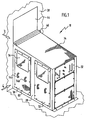
- An embodiment of an explosion protection cabinet according to the invention which in the FIGS. 1 to 4 shown there and designated as a whole by 10, comprises a receiving space 12 in which, for example, measuring arrangements or experimental equipment can be positioned.
- the receiving space is compared to an interior 14 of a room 16, in which the explosion protection cabinet 10 is arranged, gas-tightly closed (see FIG. 5 ). Opposite the free 18, the receiving space 12 is open to gas.
- the explosion protection cabinet 10 has a bottom 20 with which the explosion protection cabinet 10 is placed on a base 22 and in particular a bottom of the room 16.
- the bottom 20 is fixed to this pad 22, for example by screwing.
- 20 folds or profiles 24a, 24b are arranged on the bottom. These are in particular welded to the bottom 20.
- the folds 24a, 24b are then, for example, with the pad 22 via screw 26 ( FIG. 3 ) screwed.
- the folds 24a, 24b are preferably arranged outside of the receiving space 12, so that the bottom 20 of the explosion protection cabinet 10 does not have to be broken within the receiving space 12.
- the folds 24a, 24b are arranged on opposite narrow sides of the explosion protection cabinet 10. It is also possible in principle that they are arranged on all sides of the explosion protection cabinet 10 or on opposite longer sides.
- the explosion protection cabinet 10 comprises opposite side walls 28, 30, between which the receiving space 12 is formed.
- the explosion protection cabinet 10 has a rectangular cross-section.
- the side walls 28 are then perpendicular to the bottom 22, being parallel to each other.
- the side walls 28, 30 are gas-tightly connected to the bottom 20.
- the side walls 28, 30 are each gas-tightly connected to a front wall 32, wherein the front wall 32 is also gas-tightly connected to the bottom 20.
- the front wall 32 is perpendicular to the bottom 20 and perpendicular to the side walls 28, 30th
- a roof 34 is gas-tightly connected to the side walls 28 and 30 and the front wall 32, respectively.
- the roof 34 covers the receiving space 12 from the top of the cabinet.
- the roof 34 is designed in particular as a pent roof with an increasing inclination of the front wall 32 away.
- An inclination angle ⁇ is on the order of, for example, 5 °.
- the side walls 28, 30, the front wall 32 and the pent roof 34 is closed gas-tight on all sides.
- the connection of the individual elements is made for example by welding.
- an outer wall opening 40 is formed in an outer wall 38 of the space 16, which delimits the space 16 from the free 18.
- the explosion protection cabinet 10 is arranged with its open side 36 at this outer wall opening 40, so that a gas exchange with the free 18 can take place.
- the outer wall opening 40 is designed so that no parts of the outer wall 38 protrude into the open side 36.
- the explosion protection cabinet 10 is moved to the outer wall 38 at the outer wall opening 40. Between the explosion protection cabinet 10 and the inside (the space 16 side facing) of the outer wall 38 is a Seal 42 is arranged, which is in particular around the open side 36 of the explosion protection cabinet 10. By this seal, the space 16 is sealed against the receiving space 12 to the open side 36 gas-tight.
- the bottom 20 is screwed over the folds 24a, 24b with the base 22 so that the explosion protection cabinet 10 is pressed against the seal 42 so as to provide a seal.
- an angle plate 44 is provided, which is connected to the inside of the outer wall 38 and is connected to the roof 34.
- the connection in FIG. 4 indicated by the reference numeral 46, is designed so that the roof 34 does not have to be broken and in particular no through holes for screws or the like must be provided.
- About the angle plate 44 can be achieved in particular in combination with the seal 42 and any other seals sealing the cabinet top to the outer wall 38.
- the area between the outer wall opening 40 and the open side 36 can be fixed by means of in particular folded sheets 48 (FIG. FIG. 3 ) be covered.
- the sheets 48 are fixed to an outer side of the outer wall 38.
- the explosion protection cabinet 10 has on its open side 36 a first cross bar 50 and a second cross bar 52. Below the first cross bar 50, a non-closable inlet air opening 54 is formed in the direction of the bottom 20. About this supply air opening 54 can constantly air in the Inlet space 12 flow.
- the supply air opening 54 is associated with a protective grid 56, which is, for example, a louvred grille or a perforated plate. This guard 56 is gas permeable; it serves to provide protection against weather influences, dirt, small animals, etc. at the supply air opening 54.
- a non-closable exhaust opening 58 is formed between this second cross bar 52 and the roof 34.
- This exhaust port 58 extends into the highest area of the explosion protection cabinet 10 so that no gas accumulations can form below the roof 34. Gas can be removed from the receiving space 12 via the exhaust air opening 58. In combination with the supply air opening 54, a gas exchange in the receiving space 12 can take place.
- the exhaust port 58 is associated with a protective grid 60, for example in the form of a perforated plate or a lamella plate.
- first transverse bar 50 and the second transverse bar 52 sits on the open side 36 a plurality of lightweight panels 62a, 62b, 62c. These serve to heat-isolate the receiving space 12 with respect to the outdoor 18. They also protect the receiving space 12 against the weather, dirt, etc.
- the lightweight panels 62a, 62b, 62c are loosely stacked. They are fixed to one another, for example, by means of adhesive tape 64 and likewise fixed to the protective gratings 56, 60 via adhesive tape.
- the fixation is such that at a certain pressure in the receiving space 12, the lightweight panels 62a, 62b, 62c automatically fall out and release the open side 36.
- one or more transverse floors 66 are arranged ( FIG. 4 ). On such a transverse bottom 66 measuring devices, etc. can be turned off.
- a transverse bottom 66 is provided with a plurality of through recesses 68.
- a transverse bottom 66 is formed by means of a perforated plate. This can prevent that a gas accumulation can form below a transverse floor.
- a transverse bottom 66 is preferably flanged on all sides. This bead also contributes to the transverse bottom 66 can carry loads with minimized deflection.
- the side wall 28 is provided with a first door 70 and a second door 72.
- the two doors 70, 72 are removable as a whole.
- the door 70 and the door 72 each have a pair of spaced handles 74a, 74b on which the respective door 70, 72 can be held upon removal.
- the doors 70, 72 are each provided with a window 76.
- the window 76 is made of a pressure-resistant and unbreakable material such as Lexan. (Lexan is a registered trademark of General Electric Co.)
- the windows 76 are each in a seal 78 ( FIG. 4 ) embedded.
- the seal 78 is in particular a rubber seal.
- the doors 70, 72 are fixed to the side wall 28 of the explosion protection cabinet 10 via a plurality of rotary closures 80.
- the screw caps 80 are arranged evenly distributed in the vicinity of the side and end edges of the respective doors 70, 72.
- plate members 82 are arranged, which are removable. With the plate members 82 removed and the doors 70, 72 removed, the receiving space 12 can be accessed from three sides.
- the plate elements 82 can be fixed to the front wall 32 and the side wall 30 via rotary closures as mentioned above in connection with the doors 70, 72.
- the plate elements 82 sit over in each case a circumferential seal 84 (FIG. FIG. 2 ) on the associated wall 30 or 32. This ensures the gas-tightness of the receiving space 12 with respect to the interior 14 of the space 16.
- One or more of the plate elements 82 may be formed as a media plate 84, via the media such as gases and liquids in the receiving space 12 are coupled and / or a medium from the receiving space 12th can be coupled out and / or electrical lines in the receiving space 12 are feasible. Via such electrical lines, devices in the receiving space 12 can be supplied with energy, signals can be coupled in and signals can be removed.
- corresponding connecting elements 86 are arranged on the media plates 84, via the corresponding lines can be coupled. These are in particular bulkhead fittings that seal the passage holes of pipes and hoses through the media plates 84.
- PG glands or similar glands can be used to provide a seal.
- the roof 34 is formed as a pent roof, which is cross struts and is free of grease. Over a length of 200 cm, the pent roof rises by 15 cm in the direction of the open side 36.
- the side walls 28, 30 each have a length of 200 cm. Its height at the front wall 32 is 185 cm and at the open side 36 200 cm.
- the front wall 32 has a width of 110 cm and a height of 185 cm, respectively.
- the windows 76 in the doors have a size of 60 cm with a pane thickness of 4 mm.
- the exhaust port 58 extends at the open side 36 to 15 cm down.
- the supply air opening 54 extends at the open side 36 22 cm upwards.
- a gas sensor 88 is located below the roof 34 in an upper area of the explosion protection cabinet 10.
- it is a hydrogen-in-air sensor which measures the hydrogen concentration, for example via heat of reaction.
- the gas sensor 88 preferably sits at a distance from the highest portion of the receiving space 12 (i.e., spaced from the open side 36).
- a further gas sensor 90 is provided, which is arranged outside of the explosion protection cabinet 10 in the space 16.
- the gas sensor 90 is located above the explosion protection cabinet 10. It can thereby measure the gas concentration of a critical gas such as hydrogen outside the explosion protection cabinet 10 so as to be able to continuously monitor in particular the tightness of the explosion protection cabinet 10 with respect to the interior 14 of the room 16.
- the gas sensors 88, 90 are coupled to an emergency shut-off device, indicated as a whole by 92.
- the critical gas is coupled via a feed 94 through a corresponding media plate 84 into the working space 12 of the explosion protection cabinet 10.
- a first check valve 96 In its "normal position” locks the check valve 96th (NC normally closed).
- a controller 98 which is coupled to the gas sensor 90, opens the check valve 96 when the data supplied by the gas sensor 90 are "non-critical", ie, when no critical gas concentration is detected.
- the check valve 96 is located outside of the space 16, so that upon detection of a critical concentration, the gas supply is locked in the space 16.
- the gas sensor 88 which is arranged in the explosion protection cabinet 10, is coupled to a control device 100. This controls a check valve 102.
- the check valve 102 is normally closed (NC). Only when the concentration of the critical gas detected by the gas sensor 88 is recognized as uncritical, the control device 100 opens the check valve 102, so that the gas can be coupled into the working space 12.
- the two check valves 96 and 102 are connected in series, so that upon detection of a critical gas concentration by the gas sensor 88 or by the gas sensor 90, the gas supply is blocked in the explosion protection cabinet 10.
- the explosion protection cabinet 10 is dimensioned so that its receiving space 12 has such a volume that in an emergency shutdown and blocking of the gas supply, taking into account the remaining in the lines of the supply 94 gas volume, the explosion limit in the receiving space 12 is not reached.
- the emergency shutdown is thus so early that, taking into account the volume of the receiving space 12, a critical limit is not reached.
- the dimensioning of the explosion protection cabinet 10 is thus such that the residual content is unproblematic.
- a hydrogen-air mixture is ignitable from a hydrogen concentration of about 4%.
- it is provided, for example, that is warned at a measured concentration of 0.8% and turned off at a measured concentration of 1.6% or higher.
- the control devices 100 and 98 are coupled to a shut-off device 104 for the electrical power supply of the explosion protection cabinet 10.
- a control cabinet 106 is arranged, via which devices in the receiving space 12 can be supplied with electrical energy.
- the shutdown device 104 is coupled to the cabinet 106 and when at least one of the controllers 98 or 100 provides a critical signal, then the power supply of the cabinet 106 is turned off and thus the power supply of the explosion protection cabinet 10th
- the shutdown device 104 acts, for example, on an electromagnetic contactor 108 which is open in the ground state, i. H. does not turn on (NO). If the shutdown device 104 is not reported critical conditions, then it closes the electromagnetic contactors, d. H. ensures a through connection, so that the cabinet 106 is supplied with electrical energy. Upon detection of a critical condition, the shutdown device 104 no longer provides a signal to close the contactors 108, i. H. the connection is canceled.
- the explosion protection cabinet 10 according to the invention and the explosion protection arrangement according to the invention function as follows:
- the open side 36 opens into the open 18. Opposite the interior 14 of the space 16 is thereby achieved a gas-tight seal, while an exchange of air and gas exchange with the free 18 on the open side 36 and in particular the supply air opening 54 and the exhaust port 58 can take place.
- the explosion protection cabinet 10 is designed so that the plate elements 82, the doors 70, 72, the windows 76 and all seals can withstand an internal overpressure of at least 10 mbar.
- the cabinet construction itself is gas-tight at least up to an internal overpressure of 25 mbar.
- the lightweight components 62a, 62b, 62c are arranged so that they fall out at an internal pressure of 10 mbar.
- a passive explosion protection measure is provided by the gas sensor 88; If an excessively high gas concentration is detected, an emergency shutdown takes place via the emergency shutdown device 92 in order to prevent the further introduction of gas into the receiving space 12. Furthermore, the electrical power supply is switched off immediately.
- the inventive solution can be at a relatively low cost and relatively little technical effort an explosion protection area in a non-explosion-proof room 16 provide.
Landscapes
- Engineering & Computer Science (AREA)
- Architecture (AREA)
- Structural Engineering (AREA)
- Emergency Management (AREA)
- Environmental & Geological Engineering (AREA)
- Civil Engineering (AREA)
- Business, Economics & Management (AREA)
- Casings For Electric Apparatus (AREA)
- Gas-Insulated Switchgears (AREA)
- Buildings Adapted To Withstand Abnormal External Influences (AREA)
- Tents Or Canopies (AREA)
- Details Of Aerials (AREA)
- Patch Boards (AREA)
Description
- Die Erfindung betrifft einen Explosionsschutzschrank mit einem Aufnahmeraum, welcher eine gasdurchlässige offene Seite umfasst und an allen anderen Seiten gasdicht geschlossen ist, wobei die offene Seite ins Freie weist, und der Aufnahmeraum an der offenen Seite teilweise gegenüber dem Freien abgedeckt ist.
- Ferner betrifft die Erfindung eine Explosionsschutzanordnung in einem Raum mit einer Außenwand.
- Bei Versuchen mit kritischen Gasen wie Wasserstoff ist für genau definierte Betriebsbedingungen und genau definierte Umgebungsbedingungen eine explosionsgeschützte Umgebung erforderlich. Die Umgebung lässt sich in Zonen einteilen, wobei die explosionsgeschützte Umgebung eine besondere Zone ist. Beispielsweise liegt die Zündgrenze von Wasserstoff in Luft bei einem Volumenanteil von 4 % Wasserstoff.
- Aus der
US 5,983,578 ist ein eindringsicherer modularer Sicherheitsgang bekannt. - Aus der
US 3,334,597 ist eine strahlungssichere Struktur bekannt. - Aus der
US 3,104,628 ist eine Hochdrucklaboreinheit bekannt. - Der Erfindung liegt die Aufgabe zugrunde, einen Explosionsschutzschrank bereitzustellen, mit dem sich explosionsgefährdete Teile einer Versuchsanordnung einhausen lassen.
- Diese Aufgabe wird erfindungsgemäß dadurch gelöst, dass an der offenen Seite zwischen einer Zuluftöffnung und einer Abluftöffnung mindestens eine Leichtbauplatte so angeordnet ist, dass sie bei einem vorgegebenen Überdruck im Aufnahmeraum herausfällt.
- Bei der erfindungsgemäßen Lösung ist derjenige Teil des Explosionsschutzschranks, welcher in den Innenraum eines Raums weist, gasdicht geschlossen. Ein Gasaustausch ist jedoch mit dem Freien möglich. Dadurch lässt es sich als - passive - Explosionsschutzmaßnahme verhindern, dass sich eine zu große Konzentration eines kritischen Gases wie Wasserstoff in dem Aufnahmeraum ansammeln kann.
- Durch die erfindungsgemäße Lösung lässt sich in einem insbesondere nicht explosionsgeschützten Raum ein explosionsgeschützter Bereich abteilen. Dieser explosionsgeschützte Bereich lässt sich mit verhältnismäßig geringen Kosten und verhältnismäßig geringem technischen Aufwand bereitstellen. Durch die erfindungsgemäße Lösung ist eine Ex-Schutz-Einhausung möglich, die explosionsgefährdete Teile eines Versuchsaufbaus (wie beispielsweise eines Brennstoffzellensystems) aufnehmen kann. Die Einhausung ist dabei grundsätzlich zulassungsfähig. Es muss dann nicht der gesamte Raum umgerüstet werden.
- Der Aufnahmeraum ist an der offenen Seite teilweise gegenüber dem Freien abgedeckt, um so eben einen Schutz gegenüber Witterungseinflüssen, Schmutz usw. zu erhalten. Insbesondere ist die Abdeckung derart, dass eine Wärmeisolierung für den Aufnahmeraum gegenüber dem Freien bereitgestellt ist.
- An der offenen Seite zwischen einer Zuluftöffnung und einer Abluftöffnung ist mindestens eine Leichtbauplatte angeordnet. Da Leichtbauplatten ein relativ kleines Gewicht aufweisen, ist die Entfernung solcher Leichtbauplatten an der offenen Seite erleichtert. Es lässt sich beispielsweise bewirken, dass, wenn eine bestimmte Überdruckschwelle in dem Aufnahmeraum erreicht ist, die Leichtbauplatten von selber aus der offenen Seite herausfallen und damit eben die offene Seite freigeben.
- Insbesondere ist mindestens eine (nicht-verschließbare) Öffnung vorgesehen, welche ins Freie mündet. Über eine solche Öffnung ist ein Gasaustausch mit dem Freien möglich, so dass verhinderbar ist, dass sich kritische Gaskonzentrationen im Aufnahmeraum ansammeln können.
- Ganz besonders vorteilhaft ist es, wenn der Explosionsschutzschrank zur Positionierung an einer Außenwand mit einer Außenwandöffnung vorgesehen ist. Gegenüber dem Inneren des Raums, in dem der Explosionsschutzschrank angeordnet ist, ist eine Gasdichtigkeit gewährleistet, während Gase ins Freie abgeführt werden können.
- Günstigerweise ist die Außenwandöffnung so groß, daß die offene Seite des Aufnahmeraums nicht verdeckt wird. Es ist dann sichergestellt, daß über die Außenwand keine Blockierung, welche zu einer Einschränkung des Explosionsschutzes führen könnte, erfolgen kann.
- Bei einer Ausführungsform sind gegenüberliegende Seitenwände vorgesehen. Ferner ist eine Vorderwand vorgesehen.
- Vorteilhafterweise weist die Vorderwand eine geringere Breite auf als eine anliegende Seitenwand. Die offene Seite läßt sich dann der Vorderwand gegenüberliegend ausbilden. Dadurch lassen sich die Abmessungen der Außenwandöffnung gering halten.
- Insbesondere liegt die offene Seite der Vorderwand gegenüber.
- Ferner ist es günstig, wenn ein Boden vorgesehen ist. Dadurch läßt sich der Aufnahmeraum gegenüber dem Inneren des Raums, in dem der Explosionsschutzschrank angeordnet ist, vollständig kapseln. Über den Boden läßt sich der Explosionsschutzschrank auch an einer Unterlage (insbesondere dem Boden des Raums, in dem der Explosionsschutzschrank angeordnet ist) fixieren. Dadurch läßt es sich erreichen, daß die Schrankkonstruktion gegenüber einem inneren Überdruck wie beispielsweise 25 mbar beständig ist. Es läßt sich dadurch auch eine Abdichtung des Inneren des Raums gegenüber dem Aufnahmeraum des Explosionsschutzschranks sicherstellen.
- Es ist ferner günstig, wenn ein Dach als Deckel vorgesehen ist. Dieser sorgt für einen gasdichten Verschluß an einer Schrankoberseite.
- Es ist dann besonders vorteilhaft, wenn das Dach als Pultdach ausgebildet ist und insbesondere eine ansteigende Neigung zu der offenen Seite hin aufweist. Ein Gas wie Wasserstoff, welches leichter als Luft ist, kann dann an dem geneigten Dach entlang zu der offenen Seite hin strömen. Dadurch wiederum kann ein solches Gas leichter aus dem Aufnahmeraum abgeführt werden, um so wiederum Gasansammlungen im Aufnahmeraum zu verhindern.
- Insbesondere ist der Aufnahmeraum an fünf Seiten gasdicht geschlossen. Er ist dann an allen Seiten, welche innerhalb eines Raums liegen, gasdicht verschlossen.
- Dies kann dadurch erreicht werden, daß gegenüberliegende Seitenwände gasdicht mit einem Boden, einem Dach und einer Vorderwand verbunden sind.
- Ganz besonders vorteilhaft ist es, wenn an der offenen Seite eine ins Freie mündende Zuluftöffnung vorgesehen ist. Diese Zuluftöffnung ist stets unverschlossen. Es läßt sich dadurch garantieren, daß eine Luftzirkulation erfolgen kann, um so wiederum Gasansammlungen eines kritischen Gases wie Wasserstoff in dem Aufnahmeraum zu verhindern.
- Insbesondere ist die Zuluftöffnung in der Nähe eines Bodens des Explosionsschutzschranks angeordnet. Wenn das kritische Gas leichter als Luft ist (wie es bei Wasserstoff der Fall ist), dann ist dadurch erreicht, daß sich eine Zirkulation ausbilden kann, über die das kritische Gas aus dem Aufnahmeraum abführbar ist.
- Es ist dann ferner günstig, wenn an der offenen Seite eine ins Freie mündende Abluftöffnung vorgesehen ist. Über diese Abluftöffnung lässt sich ein kritisches Gas wie Wasserstoff aus dem Aufnahmeraum abführen.
- Ganz besonders vorteilhaft ist es, wenn die Abluftöffnung in einem bezogen auf die Schwerkraftrichtung höchsten Bereich des Explosionsschutzschranks angeordnet ist. Da Wasserstoff leichter als Luft ist, sammelt er sich bevorzugt in einem oberen Bereich des Schranks an. Er lässt sich dann über die Abluftöffnung aus diesem Bereich abführen.
- Es ist dann ferner günstig, wenn die Abluftöffnung an einem Dach oder in der Nähe eines Dachs angeordnet ist. Vorzugsweise ist das Dach geneigt. Über das geneigte Dach lässt sich Wasserstoff in Richtung eines höchsten Punkts im Explosionsschutzschrank führen. Wenn die Abluftöffnung dort angeordnet ist, dann ist für eine optimale Auskopplung gesorgt, d. h. Wasserstoff kann aktiv abgeführt werden. Dies gilt auch für andere Gase, die leichter als Luft sind.
- Zum Schutz einer Öffnung kann ein gasdurchlässiges Schutzgitter wie beispielsweise ein Lamellenblech oder ein Lochblech vorgesehen sein. Dadurch lässt sich ein Schutz des Aufnahmeraums gegenüber Witterungseinflüssen, Schmutz, Kleintieren usw. erreichen.
- Eine Abdeckung lässt sich auf einfache Weise dadurch erreichen, dass eine Mehrzahl von gestapelten Leichtbauplatten vorgesehen ist.
- Insbesondere ist die mindestens eine Leichtbauplatte lose gehalten, so dass eben ein Herausfallen möglich ist. Das lose Halten lässt sich beispielsweise dadurch realisieren, dass die mindestens eine Leichtbauplatte mit Klebeband fixiert wird. Die Haftkraft des Klebebands ist dann so, dass bei Überschreiten einer Überdruckschwelle die Halterung gelöst wird und die mindestens eine Leichtbauplatte herausfällt.
- Die mindestens eine Leichtbauplatte ist so angeordnet, dass sie bei einem vorgegebenen Überdruck im Aufnahmeraum herausfällt und damit die offene Seite freigibt. Dieser Überdruck ist beispielsweise in der Größenordnung von 10 mbar eingestellt.
- Günstigerweise ist der Explosionsschutzschrank allseitig geschlossen bis auf eine ins Freie weisende Seite. Dadurch ist ein gasdichter Abschluss gegenüber dem Inneren eines Raums, in dem der Explosionsschutzschrank angeordnet ist, erreicht. Es ist aber ein Gasaustausch mit dem Freien möglich, so daß als aktive Explosionsschutzmaßnahme die Gasansammlung in dem Aufnahmeraum vermieden wird.
- Ganz besonders vorteilhaft ist es, wenn eine Auslegung auf Überdruck gegenüber der Umgebung erfolgt. Durch eine entsprechende Überdruckfestigkeit des Explosionsschutzschranks insbesondere gegenüber dem Inneren des Raums, in dem der Explosionsschutzschrank angeordnet ist, wird eben ein Schutz erreicht. Beispielsweise ist die Überdruckfestigkeit auf einen Überdruck von der Größenordnung 25 mbar ausgelegt.
- Um Geräte und Versuchsanordnungen in dem Aufnahmeraum stapeln zu können, muß dieser unterteilt werden. Besonders vorteilhaft ist es, wenn der Aufnahmeraum mittels mindestens eines Querbodens unterteilt ist, der eine Mehrzahl von durchgehenden Öffnungen aufweist. Durch die durchgehenden Öffnungen wird ein Gasaustausch ermöglicht und dadurch wiederum verhindert, daß sich unterhalb eines Querbodens ein Gaspolster ausbilden kann. Dies trägt dazu bei, daß Ansammlungen eines kritischen Gases innerhalb des Aufnahmeraums vermieden werden. Insbesondere ist der mindestens eine Querboden mit einer seitlichen Umbördelung versehen. Dadurch wird die Steifigkeit (Stabilität gegen Durchbiegung) bei der Lagerung von Gegenständen erhöht. Insbesondere sind Umbördelungen an allen Seiten eines Querbodens vorgesehen.
- Es kann mindestens eine Tür zur Bereitstellung eines Zugangs zum Aufnahmeraum vorgesehen sein, welche als Ganzes herausnehmbar ist. Eine solche Tür läßt sich sicher mit der entsprechenden Wand fixieren.
- Insbesondere ist die mindestens eine Tür an einer Seitenwand angeordnet, wobei die Seitenwand eine entsprechende Länge aufweist.
- Eine Fixierung läßt sich auf einfache und sichere Weise erreichen, wenn eine Mehrzahl von Drehverschlüssen vorgesehen ist. Diese Drehverschlüsse sind randseitig an der Tür angeordnet, um so eine sichere Fixierung erhalten zu können.
- Günstigerweise ist mindestens eine Medienplatte vorgesehen, über die ein oder mehrere Medien in den Aufnahmeraum einkoppelbar und/oder auskoppelbar sind. Über die Medienplatte lassen sich gasförmige Medien und flüssige Medien einkoppeln bzw. auskoppeln, wobei die Einkopplung/Auskopplung auf einfache Weise möglich ist und dabei auf einfache Weise auch eine Dichtigkeit gewährleistbar ist.
- Insbesondere ist die mindestens eine Medienplatte abnehmbar und mittels einer Mehrzahl von Drehverschlüssen an der zugeordneten Wand fixierbar. Es läßt sich so eine sichere Fixierung erreichen, wobei die Einhausung des Arbeitsraums gasdicht ist. Durch die Abnehmbarkeit ergibt sich auch ein einfacher Zugriff auf den Aufnahmeraum.
- Günstigerweise ist die mindestens eine Medienplatte mit einer oder mehreren Schottverschraubungen versehen. Es lassen sich dann Leitungen wie Rohrleitungen oder Schläuche durch die Medienplatte durchführen, wobei eine Gasdichtigkeit der Durchführung gewährleistet ist.
- Ganz besonders vorteilhaft ist es, wenn eine Dichtung im Bereich der offenen Seite an einer externen Wand und/oder an einem externen Boden vorgesehen ist. Bei der Dichtung handelt es sich insbesondere um eine umlaufende Dichtung. Der erfindungsgemäße Explosionsschutzschrank wird so weit an die Dichtung herangerückt und in dieser Stellung dann fixiert, daß der Raum, in dem der Explosionsschutzschrank angeordnet ist, über die Dichtung im Bereich der Außenwand gegenüber dem Aufnahmeraum abgedichtet ist.
- Günstigerweise ist in dem Aufnahmeraum mindestens ein Gassensor angeordnet. Beispielsweise handelt es sich um einen Wasserstoff-in-Luft-Gassensor. Das Vorsehen mindestens eines Gassensors dient als aktive Explosionsschutzmaßnahme, um (vor-)kritische Gaskonzentrationen innerhalb des Aufnahmeraums detektieren zu können.
- Beispielsweise ist der mindestens eine Gassensor in der Nähe einer Schrankoberseite angeordnet. Es lassen sich dann Gase, die leichter als Luft sind (wie Wasserstoff), sicher detektieren.
- Insbesondere ist der Explosionsschutzschrank mit einer Unterlage fixiert. Beispielsweise ist ein Boden des Explosionsschutzschranks mit der Unterlage verschraubt. Es wird dadurch eine Gasdichtigkeit sichergestellt.
- Insbesondere läßt sich dadurch der Explosionsschutzschrank auch in einer Stellung gegenüber einer Außenwand fixieren, so daß hier die Gasdichtigkeit sichergestellt ist.
- Ganz besonders vorteilhaft ist es, wenn der Explosionsschutzschrank in seinem Volumen so dimensioniert ist, daß bei einer Notabschaltung einer Gaszufuhr bei Detektion einer bestimmten Gaskonzentration unter Berücksichtigung von in Leitungen und im Aufnahmeraum verbliebenem Gas eine Explosionsgrenze nicht erreicht wird. Wenn eine Notabschaltung der Gaszufuhr erfolgt, dann verbleibt in dem Leitungsbereich zwischen dem Explosionsschutzschrank und einem Sperrventil noch eine bestimmte Gasmenge. Wenn ein interner Gassensor eine bestimmte Gaskonzentration detektiert, dann bedeutet dies, daß eine bestimmte Gasmenge im Explosionsschutzschrank vorliegt. Bei der erfindungsgemäßen Dimension des Explosionsschutzschranks ist stets gewährleistet, daß die Gesamtkonzentration des Gases unterhalb einer Explosionsgrenze verbleibt.
- Der erfindungsgemäße Explosionsschutzschrank läßt sich auf einfache Weise herstellen, wenn er einen rechteckigen Querschnitt aufweist.
- Es ist günstig, wenn an mindestens einer Wand abnehmbare Plattenelemente angeordnet sind. Diese Plattenelemente können als Medienplatten und/oder einfache Plattenelemente ausgebildet sein. Es ist dadurch möglich, beispielsweise während des Aufbaus einer Versuchsanordnung von mehreren Seiten auf den Aufnahmeraum zugreifen zu können.
- Günstig ist es, wenn mindestens ein Gassensor bezogen auf die Schwerkraftrichtung oberhalb des Explosionsschutzschranks angeordnet ist. Mittels solch einem Gassensor, welcher außerhalb des Explosionsschutzschranks angeordnet ist, läßt sich die Gasdichtigkeit des Explosionsschutzschranks überwachen.
- Es läßt sich dann eine Notabschaltung durchführen, wenn in dem Raum, in dem der Explosionsschutzschrank angeordnet ist, eine zu hohe Gaskonzentration festgestellt wird.
- Insbesondere ist dazu eine Notabschalteinrichtung vorgesehen, welche bei Detektion einer bestimmten Gaskonzentration innerhalb des Explosionsschutzschranks oder außerhalb des Explosionsschutzschranks die elektrische Versorgung abschaltet und die Gaszufuhr zum Explosionsschutzschrank sperrt. Vorzugsweise erfolgt die Notabschaltung, wenn eine bestimmte Gaskonzentration entweder innerhalb oder außerhalb des Explosionsschutzschranks festgestellt wird oder eine bestimmte kritische Gaskonzentration sowohl innerhalb als auch außerhalb des Explosionsschutzschranks festgestellt wird.
- Der Erfindung liegt ferner die Aufgabe zugrunde, eine Explosionsschutzanordnung in einem Raum mit einer Außenwand bereitzustellen, welche auf einfache Weise realisierbar ist.
- Diese Aufgabe wird erfindungsgemäß dadurch gelöst, daß die Außenwand mit einer Außenwandöffnung versehen wird, an welcher ein erfindungsgemäßer Explosionsschutzschrank mit seiner offenen Seite positioniert ist.
- Die erfindungsgemäße Explosionsschutzanordnung weist die bereits im Zusammenhang mit dem erfindungsgemäßen Explosionsschutzschrank erläuterten Vorteile auf.
- Insbesondere ist der Explosionsschutzschrank gegenüber dem Rauminneren gasdicht ausgebildet.
- Vorteilhafterweise ist dazu eine Dichtung zwischen dem Explosionsschutzschrank und der Außenwand und/oder einer Unterlage für den Explosionsschutzschrank vorgesehen.
- Günstigerweise ist die Dichtung umlaufend, um so für eine vollständige Abdichtung zwischen dem Explosionsschutzschrank und der Außenwand bzw. der Unterlage und damit zwischen dem Aufnahmeraum und dem Inneren des Raums, in dem der Explosionsschutzschrank angeordnet ist, zu sorgen.
- Es ist weiterhin günstig, wenn mindestens ein Gassensor im Raum angeordnet ist. Dadurch läßt sich die Gaskonzentration im Raum überwachen. Es läßt sich dadurch die Dichtigkeit des Explosionsschutzschranks überwachen. Ferner läßt sich dadurch eine Überwachung bezüglich Leitungsbruch durchführen.
- Günstigerweise ist der Gassensor an ein Ventil gekoppelt, über welches die Gaszufuhr durch den Raum sperrbar ist. Wenn also der Gassensor eine zu hohe Konzentration detektiert, dann läßt sich damit die Gaszufuhr in den Raum selber sperren, so daß kein weiteres Gas in den Raum austreten kann.
- Insbesondere ist das Ventil als Sperrventil ausgebildet. Das Sperrventil ist in seinem Grundzustand geschlossen. Dies bedeutet, daß bei Ausfall des Gassensors oder einer Steuerungseinrichtung für das Sperrventil das Ventil geschlossen wird.
- Es ist ferner günstig, wenn in dem Aufnahmeraum mindestens ein Gassensor angeordnet ist, welcher an ein Ventil gekoppelt ist, über welches die Gaszufuhr zum Explosionsschutzschrank sperrbar ist. Wenn in dem Explosionsschutzschrank eine zu hohe Gaskonzentration detektiert wird, dann läßt sich hierüber die weitere Einkopplung von Gas in den Explosionsschutzschrank sperren.
- Aus den gleichen Gründen wie oben ist es günstig, wenn das Ventil als Sperrventil ausgebildet ist.
- Insbesondere sind die Ventile, an welche ein Gassensor im Raum und ein Gassensor im Explosionsschutzschrank gekoppelt sind, in Reihe angeordnet. Es läßt sich dann die Gaszufuhr in den Explosionsschutzschrank sperren, wenn eine zu hohe Gaskonzentration innerhalb oder außerhalb des Explosionsschutzschranks detektiert wird.
- Insbesondere ist eine Notabschalteinrichtung vorgesehen, mittels welcher sich die Energieversorgung für den Explosionsschutzschrank (für Komponenten im Explosionsschutzschrank) in Abhängigkeit von gemessenen Gaskonzentrationen abschalten läßt. Wenn eine zu hohe Gaskonzentration innerhalb des Explosionsschutzschranks oder außerhalb des Explosionsschutzschranks detektiert wird, dann läßt sich dadurch automatisch die Energieversorgung sperren.
- Die nachfolgende Beschreibung einer bevorzugten Ausführungsform dient im Zusammenhang mit der Zeichnung der näheren Erläuterung der Erfindung. Es zeigen:
- Figur 1
- eine schematische perspektivische Ansicht eines Ausführungsbeispiels eines erfindungsgemäßen Explosionsschutzschranks;
- Figur 2
- eine andere perspektivische Ansicht des Explosionsschutzschranks gemäß
Figur 1 ; - Figur 3
- eine Ansicht in der Richtung 3 gemäß
Figur 1 ; - Figur 4
- eine Seitenansicht in der Richtung 4 gemäß
Figur 1 und - Figur 5
- eine schematische Darstellung eines Ausführungsbeispiels einer erfindungsgemäßen Explosionsschutzanordnung mit einem erfindungsgemäßen Explosionsschutzschrank.
- Ein Ausführungsbeispiel eines erfindungsgemäßen Explosionsschutzschranks, welcher in den
Figuren 1 bis 4 gezeigt und dort als Ganzes mit 10 bezeichnet ist, umfaßt einen Aufnahmeraum 12, in dem beispielsweise Meßanordnungen oder Experimentieranlagen positionierbar sind. Der Aufnahmeraum ist gegenüber einem Inneren 14 eines Raums 16, in welchem der Explosionsschutzschrank 10 angeordnet ist, gasdicht verschlossen (sieheFigur 5 ). Gegenüber dem Freien 18 ist der Aufnahmeraum 12 gasdurchlässig offen. - Der Explosionsschutzschrank 10 weist einen Boden 20 auf, mit dem der Explosionsschutzschrank 10 auf einer Unterlage 22 und insbesondere einem Boden des Raums 16 aufgestellt ist. Der Boden 20 ist dabei an dieser Unterlage 22 fixiert, beispielsweise durch Verschrauben. Dazu sind an dem Boden 20 Falze oder Profile 24a, 24b angeordnet. Diese sind insbesondere mit dem Boden 20 verschweißt. Die Falze 24a, 24b sind dann beispielsweise mit der Unterlage 22 über Schraubverbindungen 26 (
Figur 3 ) verschraubt. Die Falze 24a, 24b sind dabei vorzugsweise außerhalb des Aufnahmeraums 12 angeordnet, so daß der Boden 20 des Explosionsschutzschranks 10 innerhalb des Aufnahmeraums 12 nicht durchbrochen werden muß. - Bei dem gezeigten Ausführungsbeispiel (
Figur 2 ,Figur 3 ) sind die Falze 24a, 24b an gegenüberliegenden Schmalseiten des Explosionsschutzschranks 10 angeordnet. Es ist grundsätzlich auch möglich, daß sie an allen Seiten des Explosionsschutzschranks 10 angeordnet sind oder an gegenüberliegenden längeren Seiten. - Der Explosionsschutzschrank 10 umfaßt gegenüberliegende Seitenwände 28, 30, zwischen welchen der Aufnahmeraum 12 gebildet ist. Bei einer bevorzugten Ausführungsform weist der Explosionsschutzschrank 10 einen rechteckigen Querschnitt auf. Die Seitenwände 28 liegen dann rechtwinklig zu dem Boden 22, wobei sie zueinander parallel sind. Die Seitenwände 28, 30 sind gasdicht mit dem Boden 20 verbunden.
- Die Seitenwände 28, 30 sind jeweils mit einer Vorderwand 32 gasdicht verbunden, wobei die Vorderwand 32 auch gasdicht mit dem Boden 20 verbunden ist. Die Vorderwand 32 liegt senkrecht zu dem Boden 20 und senkrecht zu den Seitenwänden 28, 30.
- An einer Schrankoberseite ist ein Dach 34 mit jeweils den Seitenwänden 28 und 30 und der Vorderwand 32 gasdicht verbunden. Das Dach 34 deckt den Aufnahmeraum 12 zu der Schrankoberseite hin ab. Das Dach 34 ist insbesondere als Pultdach ausgebildet mit einer ansteigenden Neigung von der Vorderwand 32 weg. Ein Neigungswinkel α liegt in der Größenordnung von beispielsweise 5°.
- Zu dem Inneren 14 des Raum 16 ist der Explosionsschutzschrank über den Boden 20, die Seitenwände 28, 30, die Vorderwand 32 und das Pultdach 34 allseitig gasdicht geschlossen. Die Verbindung der einzelnen Elemente ist beispielsweise über Verschweißung hergestellt.
- An der der Vorderwand 32 gegenüberliegenden Seite 36 ist der Explosionsschutzschrank 10 offen.
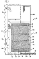
- In einer Außenwand 38 des Raums 16, welche den Raum 16 gegenüber dem Freien 18 begrenzt, ist eine Außenwandöffnung 40 gebildet. Der Explosionsschutzschrank 10 ist mit seiner offenen Seite 36 an dieser Außenwandöffnung 40 angeordnet, so daß ein Gasaustausch mit dem Freien 18 erfolgen kann. Die Außenwandöffnung 40 ist dabei so ausgebildet, daß keine Teile der Außenwand 38 in die offene Seite 36 hineinragen.
- Der Explosionsschutzschrank 10 ist an die Außenwand 38 an der Außenwandöffnung 40 herangerückt. Zwischen dem Explosionsschutzschrank 10 und der Innenseite (der dem Raum 16 zugewandten Seite) der Außenwand 38 ist eine Dichtung 42 angeordnet, die insbesondere um die offene Seite 36 des Explosionsschutzschranks 10 umlaufend ist. Durch diese Dichtung wird der Raum 16 gegenüber dem Aufnahmeraum 12 um die offene Seite 36 gasdicht abgedichtet.
- Der Boden 20 ist über die Falze 24a, 24b so mit der Unterlage 22 verschraubt, daß der Explosionsschutzschrank 10 gegen die Dichtung 42 gedrückt wird, um so für eine Abdichtung zu sorgen.
- Ferner ist ein Winkelblech 44 vorgesehen, welches mit der Innenseite der Außenwand 38 verbunden ist und mit dem Dach 34 verbunden ist. Die Verbindung (in
Figur 4 angedeutet durch das Bezugszeichen 46) ist dabei so ausgestaltet, daß das Dach 34 nicht durchbrochen werden muß und insbesondere keine Durchgangslöcher für Schrauben oder dergleichen vorgesehen werden müssen. Über das Winkelblech 44 läßt sich insbesondere in Kombination mit der Dichtung 42 und eventuellen weiteren Dichtungen eine Abdichtung der Schrankoberseite zu der Außenwand 38 erreichen. - Der Bereich zwischen der Außenwandöffnung 40 und der offenen Seite 36 kann über insbesondere gefalzte Bleche 48 (
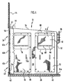
Figur 3 ) abgedeckt sein. Die Bleche 48 sind an einer Außenseite der Außenwand 38 fixiert. - Der Explosionsschutzschrank 10 weist an seiner offenen Seite 36 einen ersten Querriegel 50 und einen zweiten Querriegel 52 auf. Unterhalb des ersten Querriegels 50 ist in Richtung des Bodens 20 eine nicht verschließbare Zuluftöffnung 54 gebildet. Über diese Zuluftöffnung 54 kann ständig Luft in den Aufnahmeraum 12 einströmen. Der Zuluftöffnung 54 ist ein Schutzgitter 56 zugeordnet, bei dem es sich beispielsweise um ein Lamellengitter oder ein Lochblech handelt. Dieses Schutzgitter 56 ist gasdurchlässig; es dient dazu, an der Zuluftöffnung 54 einen Schutz gegenüber Witterungseinflüssen, Schmutz, Kleintiere usw. bereitzustellen.
- Oberhalb des zweiten Querriegels 52 ist zwischen diesem zweiten Querriegel 52 und dem Dach 34 eine nicht verschließbare Abluftöffnung 58 gebildet. Diese Abluftöffnung 58 erstreckt sich dabei in den höchsten Bereich des Explosionsschutzschranks 10, so daß sich unterhalb des Dachs 34 keine Gasansammlungen bilden können. Über die Abluftöffnung 58 läßt sich Gas aus dem Aufnahmeraum 12 abführen. In Kombination mit der Zuluftöffnung 54 kann ein Gasaustausch in dem Aufnahmeraum 12 erfolgen.
- Der Abluftöffnung 58 ist ein Schutzgitter 60 beispielsweise in der Form eines Lochblechs oder eines Lamellenblechs zugeordnet.
- Zwischen dem ersten Querriegel 50 und dem zweiten Querriegel 52 sitzt an der offenen Seite 36 eine Mehrzahl von Leichtbauplatten 62a, 62b, 62c. Diese dienen dazu, den Aufnahmeraum 12 gegenüber dem Freien 18 wärmezuisolieren. Sie schützen auch den Aufnahmeraum 12 gegenüber Witterungseinflüssen, Schmutz usw.
- Die Leichtbauplatten 62a, 62b, 62c sind lose aufeinandergestapelt. Sie werden beispielsweise über Klebeband 64 miteinander fixiert und ebenfalls über Klebeband an den Schutzgittern 56, 60 fixiert.
- Die Fixierung ist dabei so, daß bei einem bestimmten Überdruck in dem Aufnahmeraum 12 die Leichtbauplatten 62a, 62b, 62c automatisch herausfallen und die offene Seite 36 freigeben.
- Beispielsweise sind sie derart lose gehalten, daß sie beim Überdruck von 10 mbar ins Freie 18 herausfallen und damit die der Vorderwand 32 gegenüberliegende Seite 36 des Explosionsschutzschranks 10 freigeben.
- In dem Aufnahmeraum 12 sind ein oder mehrere Querböden 66 angeordnet (
Figur 4 ). Auf einem solchen Querboden 66 können Meßvorrichtungen usw. abgestellt werden. - Erfindungsgemäß ist es vorgesehen, daß ein Querboden 66 mit einer Vielzahl von durchgehenden Ausnehmungen 68 versehen ist. Beispielsweise ist ein Querboden 66 mittels eines Lochblechs gebildet. Dadurch läßt sich verhindern, daß sich eine Gasansammlung unterhalb eines Querbodens ausbilden kann. Es ist insbesondere auch vorgesehen, daß ein Querboden 66 vorzugsweise an allen Seiten umgebördelt ist. Diese Umbördelung trägt auch dazu bei, daß der Querboden 66 Lasten unter minimierter Durchbiegung tragen kann.
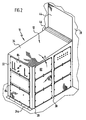
- Die Seitenwand 28 ist mit einer ersten Tür 70 und einer zweiten Tür 72 versehen. Die beiden Türen 70, 72 sind dabei als Ganzes herausnehmbar. Die Tür 70 und die Tür 72 weisen jeweils ein Paar beabstandeter Handgriffe 74a, 74b auf, an denen die jeweilige Tür 70, 72 beim Herausnehmen bzw. Einsetzen gehalten werden kann.
- Die Türen 70, 72 sind jeweils mit einem Fenster 76 versehen. Das Fenster 76 ist aus einem druckfesten und bruchsicheren Material wie Lexan hergestellt. (Lexan ist eine eingetragene Marke der General Electric Co.)
- Die Fenster 76 sind jeweils in eine Dichtung 78 (
Figur 4 ) eingebettet. Bei der Dichtung 78 handelt es sich insbesondere um eine Gummidichtung. - Die Türen 70, 72 sind über eine Mehrzahl von Drehverschlüssen 80 mit der Seitenwand 28 des Explosionsschutzschranks 10 fixiert. Die Drehverschlüsse 80 sind dabei gleichmäßig verteilt in der Nähe der Seiten- und Stirnränder der jeweiligen Türen 70, 72 angeordnet.
- An der Seitenwand 30 und der Vorderwand 32 sind Plattenelemente 82 angeordnet, die abnehmbar sind. Bei abgenommenen Plattenelementen 82 und herausgenommenen Türen 70, 72 kann auf den Aufnahmeraum 12 von drei Seiten her zugegriffen werden.
- Die Plattenelemente 82 sind über Drehverschlüsse wie oben im Zusammenhang mit den Türen 70, 72 erwähnt an der Vorderwand 32 bzw. der Seitenwand 30 fixierbar. Die Plattenelemente 82 sitzen über jeweils eine umlaufende Dichtung 84 (
Figur 2 ) an der zugeordneten Wand 30 bzw. 32. Dadurch wird die Gasdichtigkeit des Aufnahmeraums 12 gegenüber dem Inneren 14 des Raums 16 gewährleistet. - Ein oder mehrere der Plattenelemente 82 können als Medienplatte 84 ausgebildet sein, über die Medien wie Gase und Flüssigkeiten in den Aufnahmeraum 12 einkoppelbar sind und/oder ein Medium aus dem Aufnahmeraum 12 auskoppelbar ist und/oder elektrische Leitungen in den Aufnahmeraum 12 führbar sind. Über solche elektrische Leitungen lassen sich Geräte in dem Aufnahmeraum 12 mit Energie versorgen, es lassen sich Signale einkoppeln und es lassen sich Signale abführen.
- Für die Zuführung bzw. Abführung von Medien wie Gasen und Flüssigkeiten in und aus dem Explosionsschutzschrank 10 sind an den Medienplatten 84 entsprechende Verbindungselemente 86 angeordnet, über die entsprechende Leitungen ankoppelbar sind. Es handelt sich dabei insbesondere um Schottverschraubungen, die die Durchtrittslöcher von Rohren und Schläuchen durch die Medienplatten 84 abdichten.
- Für elektrische Leitungen können geprüfte und geeignete PG-Verschraubungen oder ähnliche Kabelverschraubungen verwendet werden, um für eine Abdichtung zu sorgen.
- Bei einem Ausführungsbeispiel ist das Dach 34 als Pultdach ausgebildet, welches querstrebenfrei ist und gassickenfrei ist. Auf eine Länge von 200 cm steigt das Pultdach um 15 cm in Richtung der offenen Seite 36 an. Die Seitenwände 28, 30 weisen jeweils eine Länge von 200 cm auf. Ihre Höhe an der Vorderwand 32 beträgt 185 cm und an der offenen Seite 36 200 cm. Die Vorderwand 32 weist eine Breite von 110 cm und entsprechend eine Höhe von 185 cm auf.
- Die Fenster 76 in den Türen weisen eine Größe von 60 cm bei einer Scheibendicke von 4 mm auf.
- Die Abluftöffnung 58 erstreckt sich an der offenen Seite 36 bis 15 cm nach unten. Die Zuluftöffnung 54 erstreckt sich an der offenen Seite 36 22 cm nach oben.
- Als Drehverschlüsse 80 sind 90°-Drehverschlüsse verwendet.
- In einem oberen Bereich des Explosionsschutzschranks 10 sitzt unterhalb des Dachs 34 ein Gassensor 88. Insbesondere handelt es sich um einen Wasserstoff-in-Luft-Sensor, welcher die Wasserstoffkonzentration mißt, beispielsweise über Wärmetönung. Der Gassensor 88 sitzt vorzugsweise beabstandet zu dem höchsten Bereich des Aufnahmeraums 12 (d. h. beabstandet zu der offenen Seite 36).
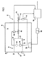
- Bei einer erfindungsgemäßen Explosionsschutzanordnung, welche schematisch in
Figur 5 gezeigt ist, ist ein weiterer Gassensor 90 vorgesehen, welcher außerhalb des Explosionsschutzschranks 10 in dem Raum 16 angeordnet ist. Vorzugsweise sitzt der Gassensor 90 oberhalb des Explosionsschutzschranks 10. Es läßt sich dadurch die Gaskonzentration eines kritischen Gases wie Wasserstoff außerhalb des Explosionsschutzschranks 10 messen, um so insbesondere die Dichtigkeit des Explosionsschutzschranks 10 gegenüber dem Inneren 14 des Raums 16 laufend überwachen zu können. - Die Gassensoren 88, 90 sind an eine als Ganzes mit 92 bezeichnete Notabschalteinrichtung gekoppelt. Das kritische Gas wird über eine Zuführung 94 durch eine entsprechende Medienplatte 84 in den Arbeitsraum 12 des Explosionsschutzschranks 10 eingekoppelt. In der Zuführung 94 sitzt ein erstes Sperrventil 96. In seiner "normalen Stellung" sperrt das Sperrventil 96 (NC-normally closed). Eine Steuerungseinrichtung 98, welche an den Gassensor 90 gekoppelt ist, öffnet das Sperrventil 96, wenn die von dem Gassensor 90 gelieferten Daten "unkritisch" sind, d. h. wenn keine kritische Gaskonzentration ermittelt wird.
- Das Sperrventil 96 sitzt außerhalb des Raums 16, so daß bei Detektion einer kritischen Konzentration die Gaszufuhr in den Raum 16 gesperrt wird.
- Der Gassensor 88, welcher in dem Explosionsschutzschrank 10 angeordnet ist, ist an eine Steuerungseinrichtung 100 gekoppelt. Diese steuert ein Sperrventil 102. Das Sperrventil 102 ist normalerweise geschlossen (NC). Nur wenn die von dem Gassensor 88 detektierte Konzentration des kritischen Gases als unkritisch erkannt wird, öffnet die Steuerungseinrichtung 100 das Sperrventil 102, so daß das Gas in den Arbeitsraum 12 einkoppelbar ist.
- Die beiden Sperrventile 96 und 102 sind in Reihe geschaltet, so daß bei Detektion einer kritischen Gaskonzentration durch den Gassensor 88 oder durch den Gassensor 90 die Gaszufuhr in den Explosionsschutzschrank 10 gesperrt wird.
- Der Explosionsschutzschrank 10 ist dabei so dimensioniert, d. h. sein Aufnahmeraum 12 weist ein solches Volumen auf, daß bei einer Notabschaltung und Sperrung der Gaszufuhr auch unter Berücksichtigung des in den Leitungen der Zuführung 94 verbliebenen Gasvolumens die Explosionsgrenze in dem Aufnahmeraum 12 nicht erreicht wird. Die Notabschaltung erfolgt also derart früh, daß unter Berücksichtigung des Volumens des Aufnahmeraums 12 eine kritische Grenze nicht erreicht wird. Die Dimensionierung des Explosionsschutzschranks 10 ist also derart, daß der Restgehalt unproblematisch ist.
- Ein Wasserstoff-Luft-Gemisch ist ab einer Wasserstoffkonzentration von ca. 4 % zündfähig. Bei der erfindungsgemäßen Lösung ist es beispielsweise vorgesehen, daß bei einer gemessenen Konzentration von 0,8 % gewarnt wird und bei einer gemessenen Konzentration von 1,6 % oder höher abgeschaltet wird.
- Die Steuerungseinrichtungen 100 und 98 sind an eine Abschalteinrichtung 104 für die elektrische Energieversorgung des Explosionsschutzschranks 10 gekoppelt. In dem Raum 16 ist beispielsweise ein Schaltschrank 106 angeordnet, über welchen Geräte in dem Aufnahmeraum 12 mit elektrischer Energie versorgbar sind. Die Abschalteinrichtung 104 ist an den Schaltschrank 106 gekoppelt und wenn mindestens eine der Steuerungseinrichtungen 98 oder 100 ein kritisches Signal liefert, dann wird die Energieversorgung des Schaltschranks 106 abgeschaltet und damit auch die Energieversorgung des Explosionsschutzschranks 10.
- Die Abschalteinrichtung 104 wirkt dazu beispielsweise auf eine elektromagnetische Schütze 108, die im Grundzustand geöffnet ist, d. h. nicht durchschaltet (NO). Wenn der Abschalteinrichtung 104 keine kritischen Bedingungen gemeldet werden, dann schließt sie die elektromagnetischen Schütze, d. h. sorgt für eine Durchschaltung, so daß der Schaltschrank 106 mit elektrischer Energie versorgt wird. Bei Detektion einer kritischen Bedingung liefert die Abschalteinrichtung 104 kein Signal mehr, um die Schütze 108 zu schließen, d. h. die Durchschaltung wird aufgehoben.
- Der erfindungsgemäße Explosionsschutzschrank 10 und die erfindungsgemäße Explosionsschutzanordnung funktionieren wie folgt:
- Durch den Explosionsschutzschrank 10 ist in dem nicht explosionsgeschützten Raum 16 ein explosionsgeschützter Bereich abgeteilt. Es ist dann nicht notwendig, den ganzen Raum 16 explosionsgeschützt auszurüsten.
- In dem Explosionsschutzschrank 10 lassen sich Messungen und Experimente beispielsweise mit Wasserstoff durchführen, wobei ein aktiver und passiver Explosionsschutz bereitgestellt wird.
- Die (schmale) Hinterseite des Explosionsschutzschranks 10, welche der Vorderwand 32 gegenüberliegt, ist offenwandig. Zu allen anderen Seiten ist der Explosionsschutzschrank 10 gasdicht geschlossen. Die offene Seite 36 mündet ins Freie 18. Gegenüber dem Inneren 14 des Raums 16 ist dadurch ein gasdichter Abschluß erreicht, während ein Luftaustausch und Gasaustausch mit dem Freien 18 über die offene Seite 36 und insbesondere die Zuluftöffnung 54 und die Abluftöffnung 58 erfolgen kann.
- Der Explosionsschutzschrank 10 ist so ausgelegt, daß die Plattenelemente 82, die Türen 70, 72, die Fenster 76 und alle Abdichtungen einen inneren Überdruck von mindestens 10 mbar aushalten. Die Schrankkonstruktion selber ist gasdicht mindestens bis zu einem inneren Überdruck von 25 mbar. Die Leichtbauelemente 62a, 62b, 62c sind so angeordnet, daß sie bei einem inneren Überdruck von 10 mbar herausfallen.
- Durch die Abluftöffnung 58 und die Zuluftöffnung 54 kann als aktive Explosionsschutzmaßnahme ein Gasaustausch erfolgen. Dadurch können sich keine Gaskonzentrationen in dem Aufnahmeraum 12 ansammeln. Der Gasaustausch erfolgt dabei mit dem Freien 18 und nicht mit dem Inneren 14 des Raums 16.
- Über weitere Maßnahmen wie Neigung des Dachs 34 und Versehen der Querböden 66 mit Ausnehmungen 68 werden Gasansammlungen innerhalb des Aufnahmeraums 12 vermieden. Weiterhin ist (wenn beispielsweise Wasserstoff das kritische Gas darstellt) die Abluftöffnung 58 direkt unterhalb des Dachs 34 angeordnet. Über das genannte Dach 34 strömt dann Wasserstoff in Richtung der Abluftöffnung 58 und kann dann aus dem Aufnahmeraum 12 abströmen.
- Durch den Gassensor 88 wiederum ist eine passive Explosionsschutzmaßnahme bereitgestellt; wenn eine zu hohe Gaskonzentration detektiert wird, dann erfolgt über die Notabschalteinrichtung 92 eine Notabschaltung, um das weitere Einkoppeln von Gas in den Aufnahmeraum 12 zu verhindern. Weiterhin wird die elektrische Energieversorgung sofort abgeschaltet.
- Durch die erfindungsgemäße Lösung läßt sich mit verhältnismäßig geringen Kosten und verhältnismäßig geringem technischen Aufwand ein Explosionsschutzbereich in einem nicht explosionsgeschützten Raum 16 bereitstellen.
Claims (49)
- Explosionsschutzschrank mit einem Aufnahmeraum (12), welcher eine gasdurchlässige offene Seite (36) umfasst und an allen anderen Seiten (28, 30, 32, 34, 20) gasdicht geschlossen ist, wobei die offene Seite ins Freie (18) weist, und der Aufnahmeraum (12) an der offenen Seite (36) teilweise gegenüber dem Freien (18) abgedeckt ist, dadurch gekennzeichnet, dass an der offenen Seite (36) zwischen einer Zuluftöffnung (54) und einer Abluftöffnung (58) mindestens eine Leichtbauplatte (62a, 62b, 62c) so angeordnet ist, dass sie bei einem vorgegebenen Überdruck im Aufnahmeraum (12) herausfällt.
- Explosionsschutzschrank nach Anspruch 1, dadurch gekennzeichnet, dass mindestens eine Öffnung (54, 58) vorgesehen ist, welche ins Freie (18) mündet.
- Explosionsschutzschrank nach einem der vorangehenden Ansprüche, dadurch gekennzeichnet, dass gegenüberliegende Seitenwände (28, 30) vorgesehen sind.
- Explosionsschutzschrank nach einem der vorangehenden Ansprüche, dadurch gekennzeichnet, dass eine Vorderwand (32) vorgesehen ist.
- Explosionsschutzschrank nach Anspruch 4, dadurch gekennzeichnet, dass die Vorderwand (32) eine geringere Breite hat als eine anliegende Seitenwand (28; 30).
- Explosionsschutzschrank nach Anspruch 4 oder 5, dadurch gekennzeichnet, dass die offene Seite (36) der Vorderwand (32) gegenüberliegt.
- Explosionsschutzschrank nach einem der vorangehenden Ansprüche, dadurch gekennzeichnet, dass ein Boden (20) vorgesehen ist.
- Explosionsschutzschrank nach einem der vorangehenden Ansprüche, dadurch gekennzeichnet, dass ein Dach (34) vorgesehen ist.
- Explosionsschutzschrank nach Anspruch 8, dadurch gekennzeichnet, dass das Dach (34) als Pultdach ausgebildet ist.
- Explosionsschutzschrank nach Anspruch 8 oder 9, dadurch gekennzeichnet, dass das Dach (34) eine ansteigende Neigung zu der offenen Seite (36) hin aufweist.
- Explosionsschutzschrank nach einem der vorangehenden Ansprüche, dadurch gekennzeichnet, dass der Aufnahmeraum (12) an fünf Seiten (28, 30, 32, 34, 20) gasdicht geschlossen ist.
- Explosionsschutzschrank nach Anspruch 11, dadurch gekennzeichnet, dass gegenüberliegende Seitenwände (28, 30) gasdicht mit einem Boden (20), einem Dach (34) und einer Vorderwand (32) verbunden sind.
- Explosionsschutzschrank nach einem der vorangehenden Ansprüche, dadurch gekennzeichnet, dass an der offenen Seite (36) eine ins Freie mündende Zuluftöffnung (54) vorgesehen ist.
- Explosionsschutzschrank nach Anspruch 13, dadurch gekennzeichnet, dass die Zuluftöffnung (54) in der Nähe eines Bodens (20) des Explosionsschutzraums angeordnet ist.
- Explosionsschutzschrank nach einem der vorangehenden Ansprüche, dadurch gekennzeichnet, dass an der offenen Seite (36) eine ins Freie mündende Abluftöffnung (58) vorgesehen ist.
- Explosionsschutzschrank nach Anspruch 15, dadurch gekennzeichnet, dass die Abluftöffnung in einem bezogen auf die Schwerkraftrichtung höchsten Bereich des Explosionsschutzschranks angeordnet ist.
- Explosionsschutzschrank nach Anspruch 15 oder 16, dadurch gekennzeichnet, dass die Abluftöffnung (58) an einem Dach (34) oder in der Nähe eines Dachs (34) angeordnet ist.
- Explosionsschutzschrank nach einem der Ansprüche 2 bis 17, dadurch gekennzeichnet, dass der mindestens einen Öffnung (54; 58) ein gasdurchlässiges Schutzgitter (56; 60) zugeordnet ist.
- Explosionsschutzschrank nach einem der vorangehenden Ansprüche, dadurch gekennzeichnet, dass eine Mehrzahl von gestapelten Leichtbauplatten (62a, 62b, 62c) vorgesehen ist.
- Explosionsschutzschrank nach einem der vorangehenden Ansprüche, dadurch gekennzeichnet, dass die mindestens eine Leichtbauplatte (62a, 62b, 62c) lose gehalten ist, um ein Herausfallen zu ermöglichen.
- Explosionsschutzschrank nach einem der vorangehenden Ansprüche, dadurch gekennzeichnet, dass der Explosionsschutzraum allseitig gasdicht geschlossen ist bis auf eine ins Freie (18) weisende Seite (36).
- Explosionsschutzschrank nach einem der vorangehenden Ansprüche, dadurch gekennzeichnet, dass der Aufnahmeraum (12) mittels mindestens eines Querbodens (66) unterteilt ist, der eine Mehrzahl von durchgehenden Öffnungen (68) aufweist.
- Explosionsschutzschrank nach einem der vorangehenden Ansprüche, dadurch gekennzeichnet, dass mindestens eine Tür (70; 72) zur Bereitstellung eines Zugangs zum Aufnahmeraum (12) vorgesehen ist, welche als Ganzes herausnehmbar ist.
- Explosionsschutzschrank nach Anspruch 23, dadurch gekennzeichnet, dass die mindestens eine Tür (70; 72) an einer Seitenwand (28) angeordnet ist.
- Explosionsschutzschrank nach Anspruch 23 oder 24, dadurch gekennzeichnet, dass die mindestens eine Tür (70; 72) mit einer Mehrzahl von Drehverschlüssen (80) an der zugeordneten Wand (28) fixierbar ist.
- Explosionsschutzschrank nach einem der vorangehenden Ansprüche, dadurch gekennzeichnet, dass mindestens eine Medienplatte (84) vorgesehen ist, über die ein oder mehrere Medien in den Aufnahmeraum einkoppelbar und/oder auskoppelbar sind.
- Explosionsschutzschrank nach Anspruch 26, dadurch gekennzeichnet, dass die mindestens eine Medienplatte (84) abnehmbar ist und mittels einer Mehrzahl von Drehverschlüssen (80) an der zugeordneten Wand (30; 32) fixierbar ist.
- Explosionsschutzschrank nach Anspruch 26 oder 27, dadurch gekennzeichnet, dass die mindestens eine Medienplatte (84) mit einer oder mehreren Schottverschraubungen versehen ist.
- Explosionsschutzschrank nach einem der vorangehenden Ansprüche, dadurch gekennzeichnet, dass eine Dichtung (42) im Bereich der offenen Seite (36) zur Anlage an eine externe Wand (38) und/oder einen externen Boden vorgesehen ist.
- Explosionsschutzschrank nach einem der vorangehenden Ansprüche, dadurch gekennzeichnet, dass ein Winkelblech (44) zur Fixierung einer Schrankoberseite (34) an einer externen Wand (38) vorgesehen ist.
- Explosionsschutzschrank nach einem der vorangehenden Ansprüche, dadurch gekennzeichnet, dass im Aufnahmeraum (12) mindestens ein Gassensor (88) angeordnet ist.
- Explosionsschutzschrank nach Anspruch 31, dadurch gekennzeichnet, dass der mindestens eine Gassensor (88) in der Nähe einer Schrankoberseite angeordnet ist.
- Explosionsschutzschrank nach einem der vorangehenden Ansprüche, dadurch gekennzeichnet, dass der Explosionsschutzschrank mit einer Unterlage (22) fixiert ist.
- Explosionsschutzschrank nach einem der vorangehenden Ansprüche, gekennzeichnet durch einen rechteckigen Querschnitt.
- Explosionsschutzschrank nach einem der vorangehenden Ansprüche, dadurch gekennzeichnet, dass an mindestens einer Wand (30; 32) abnehmbare Plattenelemente (82, 84) angeordnet sind.
- Explosionsschutzschrank nach einem der vorangehenden Ansprüche, dadurch gekennzeichnet, dass mindestens ein Gassensor (90) bezogen auf die Schwerkraftrichtung oberhalb des Explosionsschutzschranks (10) angeordnet ist.
- Explosionsschutzschrank nach einem der vorangehenden Ansprüche, dadurch gekennzeichnet, dass eine Notabschalteinrichtung (92) vorgesehen ist, welche bei Detektion einer bestimmten Gaskonzentration innerhalb des Explosionsschutzschranks (10) oder außerhalb des Explosionsschutzschranks (10) die elektrische Versorgung abschaltet und die Gaszuführung zum Explosionsschutzschrank (10) sperrt.
- Explosionsschutzanordnung in einem Raum (16) mit einer Außenwand (38), bei welcher die Außenwand (38) eine Außenwandöffnung (40) aufweist, an welcher ein Explosionsschutzschrank (10) gemäß einem der vorangehenden Ansprüche mit seiner offenen Seite (36) positioniert ist.
- Explosionsschutzanordnung nach Anspruch 38, dadurch gekennzeichnet, dass der Explosionsschutzschrank (10) gegenüber dem Rauminneren (14) gasdicht ausgebildet ist.
- Explosionsschutzanordnung nach Anspruch 38 oder 39, dadurch gekennzeichnet, dass eine Dichtung (42) zwischen Explosionsschutzschrank (10) und Außenwand (38) und/oder einem Raumboden vorgesehen ist.
- Explosionsschutzanordnung nach Anspruch 40, dadurch gekennzeichnet, dass die Dichtung (42) umlaufend ist.
- Explosionsschutzanordnung nach einem der Ansprüche 38 bis 41, dadurch gekennzeichnet, dass mindestens ein Gassensor (90) im Raum (16) anordnet ist.
- Explosionsschutzanordnung nach Anspruch 42, dadurch gekennzeichnet, dass der Gassensor (90) an ein Ventil (96) gekoppelt ist, über welches die Gaszufuhr durch den Raum (16) sperrbar ist.
- Explosionsschutzanordnung nach Anspruch 43, dadurch gekennzeichnet, dass das Ventil (96) als Sperrventil ausgebildet ist.
- Explosionsschutzanordnung nach einem der Ansprüche 38 bis 44, dadurch gekennzeichnet, dass in dem Aufnahmeraum (12) mindestens ein Gassensor (88) angeordnet ist, welcher an ein Ventil (102) gekoppelt ist, über welches die Gaszufuhr zum Explosionsschutzschrank (10) sperrbar ist.
- Explosionsschutzanordnung nach Anspruch 45, dadurch gekennzeichnet, dass das Ventil (102) als Sperrventil ausgebildet ist.
- Explosionsschutzanordnung nach einem der Ansprüche 43 bis 45, dadurch gekennzeichnet, dass Ventile (96, 102), an welche ein Gassensor (90) im Raum (16) und ein Gassensor (88) im Explosionsschutzschrank (10) gekoppelt ist, in Reihe angeordnet sind.
- Explosionsschutzanordnung nach einem der Ansprüche 38 bis 47, dadurch gekennzeichnet, dass eine Notabschalteinrichtung (92) vorgesehen ist, mittels welcher sich die Energieversorgung für den Explosionsschutzschrank (10) in Abhängigkeit von gemessenen Gaskonzentrationen abschalten lässt.
- Explosionsschutzanordnung nach einem der Ansprüche 38 bis 48, dadurch gekennzeichnet, dass die Außenwandöffnung (40) so groß ist, dass die offene Seite (36) des Aufnahmeraums (12) nicht verdeckt ist.
Applications Claiming Priority (2)
| Application Number | Priority Date | Filing Date | Title |
|---|---|---|---|
| DE102004015112 | 2004-03-27 | ||
| DE102004015112A DE102004015112A1 (de) | 2004-03-27 | 2004-03-27 | Explosionsschutzschrank und Explosionsschutzanordnung |
Publications (3)
| Publication Number | Publication Date |
|---|---|
| EP1580340A2 EP1580340A2 (de) | 2005-09-28 |
| EP1580340A3 EP1580340A3 (de) | 2010-09-01 |
| EP1580340B1 true EP1580340B1 (de) | 2012-02-22 |
Family
ID=34854091
Family Applications (1)
| Application Number | Title | Priority Date | Filing Date |
|---|---|---|---|
| EP05003835A Expired - Lifetime EP1580340B1 (de) | 2004-03-27 | 2005-02-23 | Explosionsschutzschrank und Explosionsschutzanordnung |
Country Status (4)
| Country | Link |
|---|---|
| EP (1) | EP1580340B1 (de) |
| AT (1) | ATE546600T1 (de) |
| DE (1) | DE102004015112A1 (de) |
| DK (1) | DK1580340T3 (de) |
Families Citing this family (11)
| Publication number | Priority date | Publication date | Assignee | Title |
|---|---|---|---|---|
| DE102008009552A1 (de) | 2008-02-16 | 2009-08-27 | Rittal Gmbh & Co. Kg | Schaltschrankanordnung |
| DE102008019981B4 (de) | 2008-04-21 | 2020-10-08 | Adkor Gmbh | Schrank mit wenigstens einem modularen, integrierten Energieversorgungssystem mit Brennstoffzellenstapel |
| CN102312492A (zh) * | 2011-07-08 | 2012-01-11 | 林德工程(杭州)有限公司 | 一次性现场复合的泻爆隔声墙体 |
| GB2512981B (en) * | 2014-02-05 | 2015-03-11 | Score Group Plc | Pressure test cell |
| CN105157928B (zh) * | 2015-08-20 | 2017-11-07 | 泉州施米德智能科技有限公司 | 一种高压密封测试仪 |
| CN108031035A (zh) * | 2017-12-28 | 2018-05-15 | 平湖市瑞阳精密机械有限公司 | 一种适用于灭火设备的防爆箱 |
| CN112757260B (zh) * | 2021-01-07 | 2025-01-24 | 湖南军成科技有限公司 | 一种正压防爆自动化搬运系统 |
| CN113745603B (zh) * | 2021-08-10 | 2023-06-09 | 嘉庚创新实验室 | 一种压力调节防爆装置及其电池与电池的防爆方法 |
| CN115680326B (zh) * | 2022-10-25 | 2023-08-01 | 江苏高倍智能装备有限公司 | 一种用于碳纤维车间电器防护的正压防爆房 |
| CN117307965B (zh) * | 2023-11-29 | 2024-04-09 | 广州德标智能化工程有限公司 | 移动式防爆供气柜 |
| CN119533228B (zh) * | 2024-11-26 | 2025-09-09 | 南京理工大学 | 分区隔离式地下储能系统爆炸防控措施研究装置及方法 |
Family Cites Families (9)
| Publication number | Priority date | Publication date | Assignee | Title |
|---|---|---|---|---|
| US3104628A (en) * | 1961-01-05 | 1963-09-24 | Autoclave Eng Inc | High pressure laboratory unit |
| US3334597A (en) * | 1965-07-20 | 1967-08-08 | Frances R Ruskin | Radiation-proof structure |
| DE8509333U1 (de) * | 1985-03-28 | 1985-08-22 | Drake, Francois Prosper Fernand John, London | Laboratoriums-Abzugsschrank |
| DE8813094U1 (de) * | 1988-10-18 | 1988-12-08 | Wasser, Heinz Theo, 5000 Köln | Sicherheitsvorrichtung für Laborapparaturen |
| NO178391C (no) * | 1993-08-25 | 1996-03-20 | Aspo As | Oppbevaringsskap for lösemidler, brannfarlige væsker o.l. |
| US5983578A (en) * | 1997-11-19 | 1999-11-16 | Arizona Public Service Company | Penetration-resistant security passway and door therefor |
| US6415558B1 (en) * | 2000-07-06 | 2002-07-09 | Autoquip Corporation | Tornado shelter |
| GB0211143D0 (en) * | 2002-05-15 | 2002-06-26 | Natabelle Technology Ltd | Wall panels |
| JP3921142B2 (ja) * | 2002-07-17 | 2007-05-30 | 大成建設株式会社 | 建築物 |
-
2004
- 2004-03-27 DE DE102004015112A patent/DE102004015112A1/de not_active Ceased
-
2005
- 2005-02-23 AT AT05003835T patent/ATE546600T1/de active
- 2005-02-23 DK DK05003835.5T patent/DK1580340T3/da active
- 2005-02-23 EP EP05003835A patent/EP1580340B1/de not_active Expired - Lifetime
Also Published As
| Publication number | Publication date |
|---|---|
| EP1580340A2 (de) | 2005-09-28 |
| DE102004015112A1 (de) | 2005-10-27 |
| DK1580340T3 (da) | 2012-06-18 |
| EP1580340A3 (de) | 2010-09-01 |
| ATE546600T1 (de) | 2012-03-15 |
Similar Documents
| Publication | Publication Date | Title |
|---|---|---|
| EP1580340B1 (de) | Explosionsschutzschrank und Explosionsschutzanordnung | |
| DE102007010740B4 (de) | Batterie mit Entlüftung und Verwendung der Batterie | |
| DE69304617T2 (de) | Modularer Gehäuseaufbau für Batterien | |
| DE102018100912B4 (de) | Batteriestromversorgung für ein in einem explosionsgefährdeten Bereich eingesetztes Flurförderfahrzeug und Flurförderfahrzeug | |
| DE3907049A1 (de) | Fahrzeug mit einem sicherheitssystem | |
| WO2004080540A1 (de) | Verfahren zum brand- und explosionsschutz in einem hochregallager für chemische gefahrstoffe und brand- und explosionsgeschütztes hochregallager | |
| DE112006000903T5 (de) | Aufstellungseinrichtung, Parkeinrichtung, Handhabungseinrichtung und Lüftungseinrichtung | |
| EP0878808B1 (de) | Elektrische Umspannstation | |
| DE69510589T2 (de) | Batterieschutz | |
| DE102013222269B4 (de) | Aufnahmeeinrichtung für eine elektrochemische Energiespeichereinheit | |
| EP3686959A1 (de) | Gehäuse für batterien | |
| CH626575A5 (de) | ||
| DE3609929C1 (de) | Prozessanalysator-System | |
| DE19951959A1 (de) | Wartungsschacht für Rührwerke in Biogasreaktoren mit folgeabhängigen Ventilen und Schließeinrichtungen | |
| DE102019121346B4 (de) | Deckenmodul zum Aufbau eines Reinraums | |
| DE19517241A1 (de) | Vorrichtung zum Abschotten eines Raumes | |
| EP4460435B1 (de) | Batteriesystemgerüst und verfahren zur aufnahme von mindestens einem ersten und mindestens einem benachbarten zweiten batteriemodul in einem fahrzeug zur bildung eines batteriesystems | |
| DE202005000973U1 (de) | Leitvorrichtung | |
| EP0175958B1 (de) | Kabine, insbesondere Überdruckkabine zur Sicherung elektrischer Einrichtungen unter Tage durch Fremdbelüftung | |
| DE102009004822B4 (de) | Korrosionsprüftruhe | |
| DE202018100239U1 (de) | Batteriestromversorgung für ein in einem explosionsgefährdeten Bereich eingesetztes Flurförderfahrzeug | |
| DE10348894A1 (de) | Einrichtung zum Bereitstellen von Energie und/oder Medien in einem Raum | |
| DE202019005593U1 (de) | Gefahrgutbehälter | |
| EP0238681B1 (de) | Prozessanalysator-System für industrielle Prozesse | |
| DE60018113T2 (de) | Behälter für empfindliche fracht |
Legal Events
| Date | Code | Title | Description |
|---|---|---|---|
| PUAI | Public reference made under article 153(3) epc to a published international application that has entered the european phase |
Free format text: ORIGINAL CODE: 0009012 |
|
| AK | Designated contracting states |
Kind code of ref document: A2 Designated state(s): AT BE BG CH CY CZ DE DK EE ES FI FR GB GR HU IE IS IT LI LT LU MC NL PL PT RO SE SI SK TR |
|
| AX | Request for extension of the european patent |
Extension state: AL BA HR LV MK YU |
|
| RAP1 | Party data changed (applicant data changed or rights of an application transferred) |
Owner name: DEUTSCHES ZENTRUM FUER LUFT- UND RAUMFAHRT E.V. |
|
| PUAL | Search report despatched |
Free format text: ORIGINAL CODE: 0009013 |
|
| AK | Designated contracting states |
Kind code of ref document: A3 Designated state(s): AT BE BG CH CY CZ DE DK EE ES FI FR GB GR HU IE IS IT LI LT LU MC NL PL PT RO SE SI SK TR |
|
| AX | Request for extension of the european patent |
Extension state: AL BA HR LV MK YU |
|
| RIC1 | Information provided on ipc code assigned before grant |
Ipc: E04B 1/94 20060101ALI20100727BHEP Ipc: E04B 1/98 20060101AFI20050629BHEP Ipc: E04H 9/10 20060101ALI20100727BHEP |
|
| 17P | Request for examination filed |
Effective date: 20110218 |
|
| 17Q | First examination report despatched |
Effective date: 20110325 |
|
| AKX | Designation fees paid |
Designated state(s): AT BE BG CH CY CZ DE DK EE ES FI FR GB GR HU IE IS IT LI LT LU MC NL PL PT RO SE SI SK TR |
|
| REG | Reference to a national code |
Ref country code: DE Ref legal event code: R079 Ref document number: 502005012456 Country of ref document: DE Free format text: PREVIOUS MAIN CLASS: E04B0001980000 Ipc: E04H0009060000 |
|
| RIC1 | Information provided on ipc code assigned before grant |
Ipc: E04B 1/98 20060101AFI20110725BHEP Ipc: E04B 1/94 20060101ALI20110725BHEP Ipc: E04H 9/10 20060101ALI20110725BHEP |
|
| GRAP | Despatch of communication of intention to grant a patent |
Free format text: ORIGINAL CODE: EPIDOSNIGR1 |
|
| RIC1 | Information provided on ipc code assigned before grant |
Ipc: E04B 1/94 20060101ALI20110817BHEP Ipc: E04H 9/10 20060101ALI20110817BHEP Ipc: E04B 1/98 20060101ALI20110817BHEP Ipc: E04H 9/06 20060101AFI20110817BHEP |
|
| RIN1 | Information on inventor provided before grant (corrected) |
Inventor name: BRINNER, ANDREAS Inventor name: PHILIPPS, FRANZ |
|
| GRAS | Grant fee paid |
Free format text: ORIGINAL CODE: EPIDOSNIGR3 |
|
| GRAA | (expected) grant |
Free format text: ORIGINAL CODE: 0009210 |
|
| AK | Designated contracting states |
Kind code of ref document: B1 Designated state(s): AT BE BG CH CY CZ DE DK EE ES FI FR GB GR HU IE IS IT LI LT LU MC NL PL PT RO SE SI SK TR |
|
| REG | Reference to a national code |
Ref country code: GB Ref legal event code: FG4D Free format text: NOT ENGLISH |
|
| REG | Reference to a national code |
Ref country code: CH Ref legal event code: EP |
|
| REG | Reference to a national code |
Ref country code: AT Ref legal event code: REF Ref document number: 546600 Country of ref document: AT Kind code of ref document: T Effective date: 20120315 |
|
| REG | Reference to a national code |
Ref country code: IE Ref legal event code: FG4D Free format text: LANGUAGE OF EP DOCUMENT: GERMAN |
|
| REG | Reference to a national code |
Ref country code: DE Ref legal event code: R096 Ref document number: 502005012456 Country of ref document: DE Effective date: 20120419 |
|
| REG | Reference to a national code |
Ref country code: NL Ref legal event code: T3 |
|
| REG | Reference to a national code |
Ref country code: DK Ref legal event code: T3 |
|
| LTIE | Lt: invalidation of european patent or patent extension |
Effective date: 20120222 |
|
| PG25 | Lapsed in a contracting state [announced via postgrant information from national office to epo] |
Ref country code: LT Free format text: LAPSE BECAUSE OF FAILURE TO SUBMIT A TRANSLATION OF THE DESCRIPTION OR TO PAY THE FEE WITHIN THE PRESCRIBED TIME-LIMIT Effective date: 20120222 Ref country code: IS Free format text: LAPSE BECAUSE OF FAILURE TO SUBMIT A TRANSLATION OF THE DESCRIPTION OR TO PAY THE FEE WITHIN THE PRESCRIBED TIME-LIMIT Effective date: 20120622 |
|
| PG25 | Lapsed in a contracting state [announced via postgrant information from national office to epo] |
Ref country code: FI Free format text: LAPSE BECAUSE OF FAILURE TO SUBMIT A TRANSLATION OF THE DESCRIPTION OR TO PAY THE FEE WITHIN THE PRESCRIBED TIME-LIMIT Effective date: 20120222 Ref country code: GR Free format text: LAPSE BECAUSE OF FAILURE TO SUBMIT A TRANSLATION OF THE DESCRIPTION OR TO PAY THE FEE WITHIN THE PRESCRIBED TIME-LIMIT Effective date: 20120523 Ref country code: PT Free format text: LAPSE BECAUSE OF FAILURE TO SUBMIT A TRANSLATION OF THE DESCRIPTION OR TO PAY THE FEE WITHIN THE PRESCRIBED TIME-LIMIT Effective date: 20120622 |
|
| REG | Reference to a national code |
Ref country code: IE Ref legal event code: FD4D |
|
| PG25 | Lapsed in a contracting state [announced via postgrant information from national office to epo] |
Ref country code: CY Free format text: LAPSE BECAUSE OF FAILURE TO SUBMIT A TRANSLATION OF THE DESCRIPTION OR TO PAY THE FEE WITHIN THE PRESCRIBED TIME-LIMIT Effective date: 20120222 Ref country code: MC Free format text: LAPSE BECAUSE OF NON-PAYMENT OF DUE FEES Effective date: 20120229 |
|
| REG | Reference to a national code |
Ref country code: CH Ref legal event code: PL |
|
| PG25 | Lapsed in a contracting state [announced via postgrant information from national office to epo] |
Ref country code: SE Free format text: LAPSE BECAUSE OF FAILURE TO SUBMIT A TRANSLATION OF THE DESCRIPTION OR TO PAY THE FEE WITHIN THE PRESCRIBED TIME-LIMIT Effective date: 20120222 Ref country code: LI Free format text: LAPSE BECAUSE OF NON-PAYMENT OF DUE FEES Effective date: 20120229 Ref country code: IE Free format text: LAPSE BECAUSE OF FAILURE TO SUBMIT A TRANSLATION OF THE DESCRIPTION OR TO PAY THE FEE WITHIN THE PRESCRIBED TIME-LIMIT Effective date: 20120222 Ref country code: RO Free format text: LAPSE BECAUSE OF FAILURE TO SUBMIT A TRANSLATION OF THE DESCRIPTION OR TO PAY THE FEE WITHIN THE PRESCRIBED TIME-LIMIT Effective date: 20120222 Ref country code: CH Free format text: LAPSE BECAUSE OF NON-PAYMENT OF DUE FEES Effective date: 20120229 Ref country code: SI Free format text: LAPSE BECAUSE OF FAILURE TO SUBMIT A TRANSLATION OF THE DESCRIPTION OR TO PAY THE FEE WITHIN THE PRESCRIBED TIME-LIMIT Effective date: 20120222 Ref country code: CZ Free format text: LAPSE BECAUSE OF FAILURE TO SUBMIT A TRANSLATION OF THE DESCRIPTION OR TO PAY THE FEE WITHIN THE PRESCRIBED TIME-LIMIT Effective date: 20120222 Ref country code: EE Free format text: LAPSE BECAUSE OF FAILURE TO SUBMIT A TRANSLATION OF THE DESCRIPTION OR TO PAY THE FEE WITHIN THE PRESCRIBED TIME-LIMIT Effective date: 20120222 Ref country code: PL Free format text: LAPSE BECAUSE OF FAILURE TO SUBMIT A TRANSLATION OF THE DESCRIPTION OR TO PAY THE FEE WITHIN THE PRESCRIBED TIME-LIMIT Effective date: 20120222 |
|
| PG25 | Lapsed in a contracting state [announced via postgrant information from national office to epo] |
Ref country code: IT Free format text: LAPSE BECAUSE OF FAILURE TO SUBMIT A TRANSLATION OF THE DESCRIPTION OR TO PAY THE FEE WITHIN THE PRESCRIBED TIME-LIMIT Effective date: 20120222 Ref country code: SK Free format text: LAPSE BECAUSE OF FAILURE TO SUBMIT A TRANSLATION OF THE DESCRIPTION OR TO PAY THE FEE WITHIN THE PRESCRIBED TIME-LIMIT Effective date: 20120222 |
|
| PLBE | No opposition filed within time limit |
Free format text: ORIGINAL CODE: 0009261 |
|
| STAA | Information on the status of an ep patent application or granted ep patent |
Free format text: STATUS: NO OPPOSITION FILED WITHIN TIME LIMIT |
|
| 26N | No opposition filed |
Effective date: 20121123 |
|
| GBPC | Gb: european patent ceased through non-payment of renewal fee |
Effective date: 20120522 |
|
| REG | Reference to a national code |
Ref country code: DE Ref legal event code: R097 Ref document number: 502005012456 Country of ref document: DE Effective date: 20121123 |
|
| REG | Reference to a national code |
Ref country code: AT Ref legal event code: MM01 Ref document number: 546600 Country of ref document: AT Kind code of ref document: T Effective date: 20120223 |
|
| PG25 | Lapsed in a contracting state [announced via postgrant information from national office to epo] |
Ref country code: GB Free format text: LAPSE BECAUSE OF NON-PAYMENT OF DUE FEES Effective date: 20120522 Ref country code: ES Free format text: LAPSE BECAUSE OF FAILURE TO SUBMIT A TRANSLATION OF THE DESCRIPTION OR TO PAY THE FEE WITHIN THE PRESCRIBED TIME-LIMIT Effective date: 20120602 |
|
| PG25 | Lapsed in a contracting state [announced via postgrant information from national office to epo] |
Ref country code: AT Free format text: LAPSE BECAUSE OF NON-PAYMENT OF DUE FEES Effective date: 20120223 |
|
| PG25 | Lapsed in a contracting state [announced via postgrant information from national office to epo] |
Ref country code: BG Free format text: LAPSE BECAUSE OF FAILURE TO SUBMIT A TRANSLATION OF THE DESCRIPTION OR TO PAY THE FEE WITHIN THE PRESCRIBED TIME-LIMIT Effective date: 20120522 |
|
| PG25 | Lapsed in a contracting state [announced via postgrant information from national office to epo] |
Ref country code: TR Free format text: LAPSE BECAUSE OF FAILURE TO SUBMIT A TRANSLATION OF THE DESCRIPTION OR TO PAY THE FEE WITHIN THE PRESCRIBED TIME-LIMIT Effective date: 20120222 |
|
| PG25 | Lapsed in a contracting state [announced via postgrant information from national office to epo] |
Ref country code: LU Free format text: LAPSE BECAUSE OF NON-PAYMENT OF DUE FEES Effective date: 20120223 |
|
| PG25 | Lapsed in a contracting state [announced via postgrant information from national office to epo] |
Ref country code: HU Free format text: LAPSE BECAUSE OF FAILURE TO SUBMIT A TRANSLATION OF THE DESCRIPTION OR TO PAY THE FEE WITHIN THE PRESCRIBED TIME-LIMIT Effective date: 20050223 |
|
| REG | Reference to a national code |
Ref country code: DE Ref legal event code: R082 Ref document number: 502005012456 Country of ref document: DE Representative=s name: HOEGER, STELLRECHT & PARTNER PATENTANWAELTE MB, DE |
|
| REG | Reference to a national code |
Ref country code: FR Ref legal event code: PLFP Year of fee payment: 12 |
|
| REG | Reference to a national code |
Ref country code: FR Ref legal event code: PLFP Year of fee payment: 13 |
|
| REG | Reference to a national code |
Ref country code: FR Ref legal event code: PLFP Year of fee payment: 14 |
|
| PGFP | Annual fee paid to national office [announced via postgrant information from national office to epo] |
Ref country code: DE Payment date: 20180207 Year of fee payment: 14 |
|
| REG | Reference to a national code |
Ref country code: DE Ref legal event code: R082 Ref document number: 502005012456 Country of ref document: DE Representative=s name: HOEGER, STELLRECHT & PARTNER PATENTANWAELTE MB, DE |
|
| REG | Reference to a national code |
Ref country code: DE Ref legal event code: R119 Ref document number: 502005012456 Country of ref document: DE |
|
| PG25 | Lapsed in a contracting state [announced via postgrant information from national office to epo] |
Ref country code: DE Free format text: LAPSE BECAUSE OF NON-PAYMENT OF DUE FEES Effective date: 20190903 |
|
| PGFP | Annual fee paid to national office [announced via postgrant information from national office to epo] |
Ref country code: NL Payment date: 20240111 Year of fee payment: 20 |
|
| PGFP | Annual fee paid to national office [announced via postgrant information from national office to epo] |
Ref country code: FR Payment date: 20240108 Year of fee payment: 20 Ref country code: DK Payment date: 20240130 Year of fee payment: 20 Ref country code: BE Payment date: 20240110 Year of fee payment: 20 |
|
| REG | Reference to a national code |
Ref country code: DK Ref legal event code: EUP Expiry date: 20250223 |
|
| REG | Reference to a national code |
Ref country code: NL Ref legal event code: MK Effective date: 20250222 |
|
| REG | Reference to a national code |
Ref country code: BE Ref legal event code: MK Effective date: 20250223 |