EP1580252A1 - System zur elektochemischen Sauerstoffentfernung aus einem Brennstoff - Google Patents
System zur elektochemischen Sauerstoffentfernung aus einem Brennstoff Download PDFInfo
- Publication number
- EP1580252A1 EP1580252A1 EP05251636A EP05251636A EP1580252A1 EP 1580252 A1 EP1580252 A1 EP 1580252A1 EP 05251636 A EP05251636 A EP 05251636A EP 05251636 A EP05251636 A EP 05251636A EP 1580252 A1 EP1580252 A1 EP 1580252A1
- Authority
- EP
- European Patent Office
- Prior art keywords
- fuel
- recited
- electrode
- electrochemical conversion
- conversion system
- Prior art date
- Legal status (The legal status is an assumption and is not a legal conclusion. Google has not performed a legal analysis and makes no representation as to the accuracy of the status listed.)
- Granted
Links
- 239000000446 fuel Substances 0.000 title claims abstract description 106
- 238000006392 deoxygenation reaction Methods 0.000 title description 6
- QVGXLLKOCUKJST-UHFFFAOYSA-N atomic oxygen Chemical compound [O] QVGXLLKOCUKJST-UHFFFAOYSA-N 0.000 claims abstract description 42
- 229910052760 oxygen Inorganic materials 0.000 claims abstract description 42
- 239000001301 oxygen Substances 0.000 claims abstract description 42
- 238000006243 chemical reaction Methods 0.000 claims abstract description 35
- XLYOFNOQVPJJNP-UHFFFAOYSA-N water Substances O XLYOFNOQVPJJNP-UHFFFAOYSA-N 0.000 claims abstract description 19
- 239000007788 liquid Substances 0.000 claims abstract description 9
- 238000000034 method Methods 0.000 claims description 16
- LYCAIKOWRPUZTN-UHFFFAOYSA-N Ethylene glycol Chemical compound OCCO LYCAIKOWRPUZTN-UHFFFAOYSA-N 0.000 claims description 6
- WSFSSNUMVMOOMR-UHFFFAOYSA-N Formaldehyde Chemical compound O=C WSFSSNUMVMOOMR-UHFFFAOYSA-N 0.000 claims description 6
- 230000004888 barrier function Effects 0.000 claims description 5
- 238000002156 mixing Methods 0.000 claims description 5
- 238000004891 communication Methods 0.000 claims description 4
- 239000007789 gas Substances 0.000 claims description 4
- 239000000463 material Substances 0.000 claims description 4
- 239000003795 chemical substances by application Substances 0.000 claims description 3
- LFQSCWFLJHTTHZ-UHFFFAOYSA-N Ethanol Chemical compound CCO LFQSCWFLJHTTHZ-UHFFFAOYSA-N 0.000 claims description 2
- 230000001590 oxidative effect Effects 0.000 claims 1
- 238000013022 venting Methods 0.000 claims 1
- 239000003792 electrolyte Substances 0.000 description 18
- OKKJLVBELUTLKV-UHFFFAOYSA-N Methanol Chemical compound OC OKKJLVBELUTLKV-UHFFFAOYSA-N 0.000 description 10
- 238000004939 coking Methods 0.000 description 9
- 239000012528 membrane Substances 0.000 description 9
- 239000004215 Carbon black (E152) Substances 0.000 description 4
- 229930195733 hydrocarbon Natural products 0.000 description 4
- 150000002430 hydrocarbons Chemical class 0.000 description 4
- CURLTUGMZLYLDI-UHFFFAOYSA-N Carbon dioxide Chemical compound O=C=O CURLTUGMZLYLDI-UHFFFAOYSA-N 0.000 description 3
- 229910002835 Pt–Ir Inorganic materials 0.000 description 3
- 230000008901 benefit Effects 0.000 description 3
- 238000002485 combustion reaction Methods 0.000 description 3
- 229910002092 carbon dioxide Inorganic materials 0.000 description 2
- 239000000571 coke Substances 0.000 description 2
- 239000002826 coolant Substances 0.000 description 2
- 238000010586 diagram Methods 0.000 description 2
- 238000009792 diffusion process Methods 0.000 description 2
- 238000003487 electrochemical reaction Methods 0.000 description 2
- 238000005868 electrolysis reaction Methods 0.000 description 2
- 238000012986 modification Methods 0.000 description 2
- 230000004048 modification Effects 0.000 description 2
- OKTJSMMVPCPJKN-UHFFFAOYSA-N Carbon Chemical compound [C] OKTJSMMVPCPJKN-UHFFFAOYSA-N 0.000 description 1
- 229910001260 Pt alloy Inorganic materials 0.000 description 1
- 239000004809 Teflon Substances 0.000 description 1
- 229920006362 Teflon® Polymers 0.000 description 1
- 230000002378 acidificating effect Effects 0.000 description 1
- 229910045601 alloy Inorganic materials 0.000 description 1
- 239000000956 alloy Substances 0.000 description 1
- 238000006701 autoxidation reaction Methods 0.000 description 1
- 230000015572 biosynthetic process Effects 0.000 description 1
- 239000006227 byproduct Substances 0.000 description 1
- 229910052799 carbon Inorganic materials 0.000 description 1
- 239000001569 carbon dioxide Substances 0.000 description 1
- 239000003054 catalyst Substances 0.000 description 1
- 230000008859 change Effects 0.000 description 1
- 239000003638 chemical reducing agent Substances 0.000 description 1
- 239000011248 coating agent Substances 0.000 description 1
- 238000000576 coating method Methods 0.000 description 1
- 238000000151 deposition Methods 0.000 description 1
- 230000001627 detrimental effect Effects 0.000 description 1
- 238000004090 dissolution Methods 0.000 description 1
- -1 e.g. Inorganic materials 0.000 description 1
- 230000000694 effects Effects 0.000 description 1
- 239000010795 gaseous waste Substances 0.000 description 1
- 230000001939 inductive effect Effects 0.000 description 1
- 238000002347 injection Methods 0.000 description 1
- 239000007924 injection Substances 0.000 description 1
- 150000002500 ions Chemical class 0.000 description 1
- 238000010030 laminating Methods 0.000 description 1
- 238000012423 maintenance Methods 0.000 description 1
- 238000007254 oxidation reaction Methods 0.000 description 1
- 238000012545 processing Methods 0.000 description 1
- 239000000047 product Substances 0.000 description 1
- 238000007348 radical reaction Methods 0.000 description 1
- 150000003254 radicals Chemical class 0.000 description 1
- 230000009467 reduction Effects 0.000 description 1
- 230000006641 stabilisation Effects 0.000 description 1
- 238000011105 stabilization Methods 0.000 description 1
- 239000010935 stainless steel Substances 0.000 description 1
- 229910001220 stainless steel Inorganic materials 0.000 description 1
- 238000012546 transfer Methods 0.000 description 1
Images

Classifications
-
- C—CHEMISTRY; METALLURGY
- C10—PETROLEUM, GAS OR COKE INDUSTRIES; TECHNICAL GASES CONTAINING CARBON MONOXIDE; FUELS; LUBRICANTS; PEAT
- C10G—CRACKING HYDROCARBON OILS; PRODUCTION OF LIQUID HYDROCARBON MIXTURES, e.g. BY DESTRUCTIVE HYDROGENATION, OLIGOMERISATION, POLYMERISATION; RECOVERY OF HYDROCARBON OILS FROM OIL-SHALE, OIL-SAND, OR GASES; REFINING MIXTURES MAINLY CONSISTING OF HYDROCARBONS; REFORMING OF NAPHTHA; MINERAL WAXES
- C10G32/00—Refining of hydrocarbon oils by electric or magnetic means, by irradiation, or by using microorganisms
- C10G32/02—Refining of hydrocarbon oils by electric or magnetic means, by irradiation, or by using microorganisms by electric or magnetic means
-
- B—PERFORMING OPERATIONS; TRANSPORTING
- B01—PHYSICAL OR CHEMICAL PROCESSES OR APPARATUS IN GENERAL
- B01D—SEPARATION
- B01D19/00—Degasification of liquids
-
- C—CHEMISTRY; METALLURGY
- C02—TREATMENT OF WATER, WASTE WATER, SEWAGE, OR SLUDGE
- C02F—TREATMENT OF WATER, WASTE WATER, SEWAGE, OR SLUDGE
- C02F1/00—Treatment of water, waste water, or sewage
- C02F1/46—Treatment of water, waste water, or sewage by electrochemical methods
-
- H—ELECTRICITY
- H01—ELECTRIC ELEMENTS
- H01M—PROCESSES OR MEANS, e.g. BATTERIES, FOR THE DIRECT CONVERSION OF CHEMICAL ENERGY INTO ELECTRICAL ENERGY
- H01M8/00—Fuel cells; Manufacture thereof
- H01M8/06—Combination of fuel cells with means for production of reactants or for treatment of residues
- H01M8/0662—Treatment of gaseous reactants or gaseous residues, e.g. cleaning
-
- H—ELECTRICITY
- H01—ELECTRIC ELEMENTS
- H01M—PROCESSES OR MEANS, e.g. BATTERIES, FOR THE DIRECT CONVERSION OF CHEMICAL ENERGY INTO ELECTRICAL ENERGY
- H01M8/00—Fuel cells; Manufacture thereof
- H01M8/10—Fuel cells with solid electrolytes
- H01M2008/1095—Fuel cells with polymeric electrolytes
-
- Y—GENERAL TAGGING OF NEW TECHNOLOGICAL DEVELOPMENTS; GENERAL TAGGING OF CROSS-SECTIONAL TECHNOLOGIES SPANNING OVER SEVERAL SECTIONS OF THE IPC; TECHNICAL SUBJECTS COVERED BY FORMER USPC CROSS-REFERENCE ART COLLECTIONS [XRACs] AND DIGESTS
- Y02—TECHNOLOGIES OR APPLICATIONS FOR MITIGATION OR ADAPTATION AGAINST CLIMATE CHANGE
- Y02E—REDUCTION OF GREENHOUSE GAS [GHG] EMISSIONS, RELATED TO ENERGY GENERATION, TRANSMISSION OR DISTRIBUTION
- Y02E60/00—Enabling technologies; Technologies with a potential or indirect contribution to GHG emissions mitigation
- Y02E60/30—Hydrogen technology
- Y02E60/50—Fuel cells
Definitions
- the present invention relates to the removal of dissolved oxygen from fuels, and more particularly to electrochemically converting the oxygen to water.
- Jet fuel is often utilized in aircraft as a coolant for various systems in the aircraft. Dissolution of air in jet fuel results in an approximately 70 ppm oxygen concentration.
- aerated fuel is heated between 350°F (177°C) and 850°F (454°C) the oxygen initiates free radical reactions of the fuel resulting in deposits commonly referred to as "coke” or "coking.” Coke may be detrimental to the fuel lines and may inhibit combustion. The formation of such deposits may impair the normal functioning of a fuel delivery system, either with respect to an intended heat exchange function or the efficient injection of fuel.
- FSU Fuel Stabilization Unit
- One conventional Fuel Stabilization Unit (FSU) utilized in the aircraft field removes oxygen from jet fuel by inducing an oxygen pressure gradient across a membrane permeable to oxygen. Although quite effective, the gradient is produced by vacuum on one side of the membrane. As the vacuum also introduces mechanical forces on the membrane, the membrane is supported on a porous stainless steel plate, which is relatively expensive and may be a diffusion barrier requiring a relative increase in the unit size. Mechanical pumps and vacuum housings are also required which further increases the size and weight of the system.
- FSU Fuel Stabilization Unit
- the fuel system for an energy conversion device includes a deoxygenator system with an electrochemical conversion system that removes oxygen from the fuel through conversion of oxygen to water.
- the preferred electrochemical conversion system includes a first electrode, a second electrode, and an electrolyte therebetween such as is commonly referred to as a proton exchange membrane fuel cell.
- the first electrode is located in contact with a fuel flow.
- the water may remain in the fuel stream or be absorbed into the electrolyte.
- the second electrode is separated from the first electrode and the fuel stream by the electrolyte.
- many reactions may occur.
- H 2 0 1 ⁇ 2O 2 + 2H + +2e - , occurs and, thus, water is consumed and oxygen liberated.
- the device acts like an electrochemical oxygen pump removing oxygen from the fuel stream at the first electrode and depositing it at the second electrode separated from the fuel stream by the electrolyte.
- the water consumed at the second electrode must be supplied by the electrolyte or externally.
- the oxygen liberated at the second electrode must be vented.
- the present invention eliminates conventional oxygen permeable membranes as the electrode directly contacts the fuel.
- the present invention also eliminates the need for a absolute pressure differences, oxygen permeable membranes, and components with moving parts such as pumps.
- the present invention therefore provides a method and system for the deoxygenation of hydrocarbon fuel to minimize coking in an inexpensive, size and weight efficient system.
- FIG. 1 illustrates a general perspective view of a fuel system 10 for an energy conversion device (ECD) 12.
- a deoxygenator system 14 receives liquid fuel F from a reservoir 16.
- the fuel F is typically a hydrocarbon such as jet fuel.
- the ECD 12 may exist in a variety of forms in which the fuel, at some point prior to eventual use for processing, for combustion or for some form of energy release, acquires sufficient heat to support autoxidation reactions and coking if dissolved oxygen is present to any significant extent in the fuel.
- ECD 12 is a gas turbine engine, and particularly such engines in high performance aircraft.
- the fuel also serves as a coolant for one or more sub-systems in the aircraft, and in any event becomes heated as it is delivered to fuel injectors immediately prior to combustion.
- a heat exchange section 18 represents a system through which the fuel passes in a heat exchange relationship. It should be understood that the heat exchange section 18 may be directly associated with the ECD 12 and/or distributed elsewhere in the larger system.
- the heat exchange system 18 may alternatively or additionally include a multiple of heat exchanges distributed throughout the system.
- fuel F stored in the reservoir 16 normally contains dissolved oxygen, possibly at a saturation level of 70 ppm.
- a fuel pump 20 draws the fuel F from the reservoir 16.
- the fuel pump 20 communicates with the reservoir 16 via a fuel reservoir conduit 22 and a valve 24 to a fuel inlet 26 of the deoxygenator system 14.
- the pressure applied by pump 20 assists in circulating the fuel F through the deoxygenator system 14 and other portions of the fuel system 10.
- oxygen dissolved in the fuel is selectively converted to water W which either remains in the fuel F or is absorbed into the deoxygenator system.
- the deoxygenator system consumes water supplied by reservoir 28 and generates oxygen, which is collected and/or expelled from the system 10 at 28.
- the deoxygenated fuel F preferably with a dissolved oxygen concentration of 2 ppm or below, flows from a fuel outlet 30 of the deoxygenation system 14 via a deoxygenated fuel conduit 32, to the heat exchange system 18 and to the ECD 12 such as the fuel injectors of a gas turbine engine.
- a portion of the deoxygenated fuel may be recirculated, as represented by recirculation conduit 34 to either the deoxygenation system 14 and/or the reservoir 16.
- the deoxygenator system 14 preferably includes an electrochemical conversion system 36 that removes oxygen from the fuel through conversion of the oxygen to water.
- the electrochemical conversion system 36 is located along a fuel conduit 38 (illustrated schematically).
- the electrochemical conversion system 36 is preferably sized to remove oxygen at a rate commensurate with fuel flow to the ECD 12.
- the electrochemical conversion system 36 12 thereby removes oxygen during online operation of the ECD 12 at flow rates consistent with fuel usage.
- the electrochemical conversion system 36 may be located anywhere in the fuel system 10 prior to the ECD 12 and may take various shapes other than a straight conduit which may alternatively or additionally provide convective transfer of oxygen to the device surface and/or lower diffusional distances.
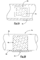
- the electrochemical conversion system 36 includes a first electrode 40 a second electrode 42, and an electrolyte 44 therebetween such as is commonly referred to as an ionically conducting member or proton exchange-electrolyte.
- the first electrode 40 and second electrode 42 are normally made porous and electrically conducting while the electrolyte 44 is substantially non-porous and electrically insulating.
- the electrodes and electrolyte are usually laminated together forming a mechanical bond and allowing ions to transport among three components.
- the first electrode 40 and second electrode 42 must be electrically isolated from each other and preferably from the fuel conduit 38. This is preferably accomplished by laminating the first and second electrodes with an electrolyte member that is physically larger than either electrode into assembly 36.
- the electrolyte 44 preferably forms a portion of the fuel conduit 38 such that the first electrode is in communication with the fuel flow.
- the electrode-electrolyte assembly is illustrated as a relatively linear member in Figure 2, it should be understood that this assembly 36a may alternatively or additionally be of any configuration and form any portion of the fuel conduit 38a such as a tubular section or the like ( Figure 3A).
- the materials of the first and second electrodes 40, 42 are preferably Pt or Pt-alloys, e.g., Pt-Ir, pure or supported on carbon.
- the Pt-Ir is most preferred for the second electrode 42.
- the membrane electrolyte 44 is preferably ionically conducting and should not be construed as limited to a proton exchange membranes.
- the electrochemical conversion system 36 is powered by a power source 46.
- the electrochemical conversion system 36 forms a concentration cell with an equilibrium Nernst potential of 22mV at 25°C for a concentration difference of 70 to 2 ppm. Approximately 22 mV + overpotential need only be supplied to affect the desired concentration reduction.
- the first electrode 40 is located within the fuel conduit 38 in contact with a fuel flow F.
- the electrode may be located in a communication path of or within the fuel F.
- the first electrode 40 is shown as a thin, uniform layer in Figure 2, the first electrode 40 is preferably fabricated with a surface texture and/or of a configuration which assists in the mixing of laminar flow boundary layers to shorten diffusion lengths.
- the electrochemical conversion system 36 may alternatively or additionally be fabricated with the first electrode 40a as a mixer insert (illustrated schematically at Figure 3B). More complex geometries for the electrochemical system 36 are possible and may further improve mixing.
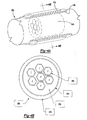
- an electrochemical system 36b as a tubular shape which forms a section of the fuel conduit 38b
- the first electrode 40b may be formed as a honeycomb structure (Figure 4B)
- the electrolyte 44b is tubular in shape and forms a section of the fuel conduit 38b
- the second electrode 42b is a coating on the outside of the electrolyte tube 44b which is shorter than the electrolyte tube and is electrically isolated from the fuel conduit 38b That is, the first electrode 40 is located in contact with the fuel while the second electrode 42b is physically isolated and located in a position to provide for the expulsion of the generated oxygen or other gaseous waste products.
- the first electrode 40 may be macro-porous and fill the space within the fuel conduit so as to improve oxygen diffusional characteristics to the fuel stream.
- Fuel is generally inert and will not be harmed by the acidic environment adjacent the first electrode 40.
- the first electrode 40 may be coated with a barrier material 48 to limit fouling.
- the barrier 48 or 48b is preferably manufactured of a Teflon (AAF2400) or Hyflon (100) barrier material.
- the overpotential for the water electrolysis reaction outside the fuel can be lowered by using an alloy catalyst such as Pt-Ir and/or adding a reducing agent to the fuel, such as ⁇ 100 ppm methanol, to lower the potential of the electrode outside of the fuel.
- Methanol added to the fuel stream will be absorbed into the electrolyte 44 and transmitted to the second electrode 42.
- an oxidisable agent may be added to the fuel preferably in concentrations of about 0-100 ppm.
- An alcohol, formaldehyde or ethylene glycol can be added to the fuel.
- the oxygen or carbon dioxide generated as the second electrode 42 must be vented to the atmosphere so a high gas pressure does not occur in the deoxygenator. Also, the electrochemical reactions at the second electrode 42 require water.
- the reservoir 28 provides both functions in the system shown in Figure 1. This is a preferred embodiment, but not essential to this invention.
Landscapes
- Chemical & Material Sciences (AREA)
- Chemical Kinetics & Catalysis (AREA)
- General Chemical & Material Sciences (AREA)
- Life Sciences & Earth Sciences (AREA)
- Engineering & Computer Science (AREA)
- Oil, Petroleum & Natural Gas (AREA)
- Organic Chemistry (AREA)
- Electrochemistry (AREA)
- Manufacturing & Machinery (AREA)
- Microbiology (AREA)
- Sustainable Development (AREA)
- Sustainable Energy (AREA)
- Water Supply & Treatment (AREA)
- Environmental & Geological Engineering (AREA)
- Hydrology & Water Resources (AREA)
- Production Of Liquid Hydrocarbon Mixture For Refining Petroleum (AREA)
- Electrolytic Production Of Non-Metals, Compounds, Apparatuses Therefor (AREA)
- Feeding And Controlling Fuel (AREA)
- Liquid Carbonaceous Fuels (AREA)
Applications Claiming Priority (2)
| Application Number | Priority Date | Filing Date | Title |
|---|---|---|---|
| US810796 | 2004-03-26 | ||
| US10/810,796 US7431818B2 (en) | 2004-03-26 | 2004-03-26 | Electrochemical fuel deoxygenation system |
Publications (2)
| Publication Number | Publication Date |
|---|---|
| EP1580252A1 true EP1580252A1 (de) | 2005-09-28 |
| EP1580252B1 EP1580252B1 (de) | 2011-07-27 |
Family
ID=34862116
Family Applications (1)
| Application Number | Title | Priority Date | Filing Date |
|---|---|---|---|
| EP05251636A Expired - Lifetime EP1580252B1 (de) | 2004-03-26 | 2005-03-17 | System zur elektrochemischen Sauerstoffentfernung aus einem Brennstoff |
Country Status (7)
| Country | Link |
|---|---|
| US (1) | US7431818B2 (de) |
| EP (1) | EP1580252B1 (de) |
| JP (1) | JP2005281695A (de) |
| KR (1) | KR100656864B1 (de) |
| CN (1) | CN1683830A (de) |
| AT (1) | ATE517972T1 (de) |
| CA (1) | CA2496930A1 (de) |
Cited By (4)
| Publication number | Priority date | Publication date | Assignee | Title |
|---|---|---|---|---|
| EP1908506A2 (de) | 2006-10-05 | 2008-04-09 | United Technologies Corporation | Elektromechanische Sauerstoffpumpe für eine Brennstoffstabilisierungseinheit |
| EP1918424A1 (de) | 2006-10-16 | 2008-05-07 | United Technologies Corporation | Elektrochemische Sauerstoffentfernung aus Brennstoff durch Elektrolyse |
| WO2008116781A1 (de) * | 2007-03-28 | 2008-10-02 | Robert Bosch Gmbh | Vorrichtung und verfahren zur erzeugung elektrischer energie |
| WO2019055602A3 (en) * | 2017-09-14 | 2019-04-18 | Baker Hughes, A Ge Company, Llc | ELECTROCHEMICAL METHODS FOR REMOVING OXYGEN DISSOLVED FROM DRILLING OR COMPLETION FLUIDS |
Families Citing this family (34)
| Publication number | Priority date | Publication date | Assignee | Title |
|---|---|---|---|---|
| US7882704B2 (en) * | 2007-01-18 | 2011-02-08 | United Technologies Corporation | Flame stability enhancement |
| US9580185B2 (en) | 2012-01-20 | 2017-02-28 | Hamilton Sundstrand Corporation | Small engine cooled cooling air system |
| US8876946B2 (en) | 2012-04-03 | 2014-11-04 | Hamilton Sundstrand Corporation | Combined fuel stabilization unit and heat exchanger |
| US9789972B2 (en) * | 2014-06-27 | 2017-10-17 | Hamilton Sundstrand Corporation | Fuel and thermal management system |
| US10215097B2 (en) | 2015-12-08 | 2019-02-26 | General Electric Company | Thermal management system |
| US10823072B2 (en) | 2018-04-02 | 2020-11-03 | Raytheon Technologies Corporation | Passive fuel additives dosing system |
| US11085636B2 (en) | 2018-11-02 | 2021-08-10 | General Electric Company | Fuel oxygen conversion unit |
| US11161622B2 (en) | 2018-11-02 | 2021-11-02 | General Electric Company | Fuel oxygen reduction unit |
| US11420763B2 (en) | 2018-11-02 | 2022-08-23 | General Electric Company | Fuel delivery system having a fuel oxygen reduction unit |
| US11319085B2 (en) | 2018-11-02 | 2022-05-03 | General Electric Company | Fuel oxygen conversion unit with valve control |
| US11131256B2 (en) | 2018-11-02 | 2021-09-28 | General Electric Company | Fuel oxygen conversion unit with a fuel/gas separator |
| US11577852B2 (en) | 2018-11-02 | 2023-02-14 | General Electric Company | Fuel oxygen conversion unit |
| US11186382B2 (en) | 2018-11-02 | 2021-11-30 | General Electric Company | Fuel oxygen conversion unit |
| US11447263B2 (en) | 2018-11-02 | 2022-09-20 | General Electric Company | Fuel oxygen reduction unit control system |
| US11193671B2 (en) | 2018-11-02 | 2021-12-07 | General Electric Company | Fuel oxygen conversion unit with a fuel gas separator |
| US11851204B2 (en) | 2018-11-02 | 2023-12-26 | General Electric Company | Fuel oxygen conversion unit with a dual separator pump |
| US11148824B2 (en) | 2018-11-02 | 2021-10-19 | General Electric Company | Fuel delivery system having a fuel oxygen reduction unit |
| US11193420B2 (en) | 2018-11-16 | 2021-12-07 | United Technologies Corporation | System and method for monitoring fuel additives |
| US11015534B2 (en) | 2018-11-28 | 2021-05-25 | General Electric Company | Thermal management system |
| US11391211B2 (en) | 2018-11-28 | 2022-07-19 | General Electric Company | Waste heat recovery system |
| CN110661014B (zh) * | 2019-08-21 | 2022-02-08 | 中国矿业大学 | 一种高效低浓度瓦斯发电系统及其控制方法 |
| CN110551542A (zh) * | 2019-08-21 | 2019-12-10 | 中国矿业大学 | 利用低浓度瓦斯制备高浓度甲烷气体的控制系统及方法 |
| US10914274B1 (en) | 2019-09-11 | 2021-02-09 | General Electric Company | Fuel oxygen reduction unit with plasma reactor |
| US11774427B2 (en) | 2019-11-27 | 2023-10-03 | General Electric Company | Methods and apparatus for monitoring health of fuel oxygen conversion unit |
| US11773776B2 (en) | 2020-05-01 | 2023-10-03 | General Electric Company | Fuel oxygen reduction unit for prescribed operating conditions |
| US11906163B2 (en) | 2020-05-01 | 2024-02-20 | General Electric Company | Fuel oxygen conversion unit with integrated water removal |
| US11866182B2 (en) | 2020-05-01 | 2024-01-09 | General Electric Company | Fuel delivery system having a fuel oxygen reduction unit |
| CN111921267A (zh) * | 2020-07-23 | 2020-11-13 | 华友新能源科技(衢州)有限公司 | 一种前驱体合成中稳定分离母液的方法 |
| US11434824B2 (en) | 2021-02-03 | 2022-09-06 | General Electric Company | Fuel heater and energy conversion system |
| US11591965B2 (en) | 2021-03-29 | 2023-02-28 | General Electric Company | Thermal management system for transferring heat between fluids |
| US12139270B2 (en) | 2021-04-19 | 2024-11-12 | General Electric Company | Aircraft thermal transport system and method |
| US12115470B2 (en) | 2021-04-27 | 2024-10-15 | General Electric Company | Fuel oxygen reduction unit |
| US12005377B2 (en) | 2021-06-15 | 2024-06-11 | General Electric Company | Fuel oxygen reduction unit with level control device |
| US11542870B1 (en) | 2021-11-24 | 2023-01-03 | General Electric Company | Gas supply system |
Citations (5)
| Publication number | Priority date | Publication date | Assignee | Title |
|---|---|---|---|---|
| US1376180A (en) * | 1920-06-29 | 1921-04-26 | Elmer E Wickersham | Process of treating liquid fuel |
| US4539086A (en) * | 1983-08-31 | 1985-09-03 | Japan Storage Battery Company Limited | Oxygen concentration controlling method and system |
| WO1995027810A1 (en) * | 1994-04-12 | 1995-10-19 | Oxycell, Inc. | Oxygen supply and removal apparatus |
| US20030136661A1 (en) * | 2002-01-23 | 2003-07-24 | Bechtel Bwxt Idaho, Llc | Apparatus and methods for direct conversion of gaseous hydrocarbons to liquids |
| WO2003081702A2 (en) * | 2002-03-21 | 2003-10-02 | Symyx Technologies, Inc. | Fuel cell catalyst containing pt and rh and at least one of w, sn and cu and optionally mo. |
Family Cites Families (13)
| Publication number | Priority date | Publication date | Assignee | Title |
|---|---|---|---|---|
| US3933638A (en) * | 1974-06-07 | 1976-01-20 | Teledyne Industries, Inc. | Liquid fuel purification system |
| IT1202425B (it) | 1987-01-26 | 1989-02-09 | Giuseppe Bianchi | Processo elettrochimico di deossigenazione per il controllo della corrosione in acque deionizzate |
| US4776536A (en) | 1987-05-19 | 1988-10-11 | Rockwell International Corporation | Integrated aircraft fuel thermal management system |
| FI922485A7 (fi) | 1992-05-29 | 1993-11-30 | Seppo Tapio Ylaesaari | Elektrokemiskt foerfarande och anordning foer avlaegsnande av syre ur vatten eller vattenloesningar |
| US5275000A (en) | 1992-08-17 | 1994-01-04 | General Electric Company | Reducing thermal deposits in endothermic fuel reactors of propulsion systems |
| US5423178A (en) | 1992-09-28 | 1995-06-13 | Parker-Hannifin Corporation | Multiple passage cooling circuit method and device for gas turbine engine fuel nozzle |
| US5575153A (en) | 1993-04-07 | 1996-11-19 | Hitachi, Ltd. | Stabilizer for gas turbine combustors and gas turbine combustor equipped with the stabilizer |
| WO1995007857A1 (en) * | 1993-09-13 | 1995-03-23 | David Reznik | Apparatus and method for reducing the redox potential of substances |
| DE19821766C1 (de) | 1998-05-14 | 1999-06-24 | Siemens Ag | PEM-Brennstoffzellensystem mit Befeuchtung und/oder Kühlung mit flüssigem Medium, deren Verwendung sowie ein Verfahren zum Befeuchten und Kühlen eines solchen Systems |
| US6315815B1 (en) | 1999-12-16 | 2001-11-13 | United Technologies Corporation | Membrane based fuel deoxygenator |
| WO2001078820A1 (en) * | 2000-04-18 | 2001-10-25 | Teijin Limited | Oxygen concentrating apparatus |
| EP1170259A1 (de) * | 2000-07-05 | 2002-01-09 | Sony International (Europe) GmbH | Elekrochemische Vorrichtung und Verfahren zur Reinigung von Flüssigkeiten |
| JP2003327408A (ja) | 2002-05-10 | 2003-11-19 | Mitsubishi Electric Corp | 燃料処理装置およびその運転方法 |
-
2004
- 2004-03-26 US US10/810,796 patent/US7431818B2/en not_active Expired - Lifetime
-
2005
- 2005-02-04 KR KR1020050010303A patent/KR100656864B1/ko not_active Expired - Fee Related
- 2005-02-11 CA CA002496930A patent/CA2496930A1/en not_active Abandoned
- 2005-03-17 EP EP05251636A patent/EP1580252B1/de not_active Expired - Lifetime
- 2005-03-17 AT AT05251636T patent/ATE517972T1/de not_active IP Right Cessation
- 2005-03-25 JP JP2005090073A patent/JP2005281695A/ja active Pending
- 2005-03-25 CN CNA2005100627199A patent/CN1683830A/zh active Pending
Patent Citations (5)
| Publication number | Priority date | Publication date | Assignee | Title |
|---|---|---|---|---|
| US1376180A (en) * | 1920-06-29 | 1921-04-26 | Elmer E Wickersham | Process of treating liquid fuel |
| US4539086A (en) * | 1983-08-31 | 1985-09-03 | Japan Storage Battery Company Limited | Oxygen concentration controlling method and system |
| WO1995027810A1 (en) * | 1994-04-12 | 1995-10-19 | Oxycell, Inc. | Oxygen supply and removal apparatus |
| US20030136661A1 (en) * | 2002-01-23 | 2003-07-24 | Bechtel Bwxt Idaho, Llc | Apparatus and methods for direct conversion of gaseous hydrocarbons to liquids |
| WO2003081702A2 (en) * | 2002-03-21 | 2003-10-02 | Symyx Technologies, Inc. | Fuel cell catalyst containing pt and rh and at least one of w, sn and cu and optionally mo. |
Cited By (7)
| Publication number | Priority date | Publication date | Assignee | Title |
|---|---|---|---|---|
| EP1908506A2 (de) | 2006-10-05 | 2008-04-09 | United Technologies Corporation | Elektromechanische Sauerstoffpumpe für eine Brennstoffstabilisierungseinheit |
| EP1908506A3 (de) * | 2006-10-05 | 2010-06-30 | United Technologies Corporation | Elektromechanische Sauerstoffpumpe für eine Brennstoffstabilisierungseinheit |
| EP1918424A1 (de) | 2006-10-16 | 2008-05-07 | United Technologies Corporation | Elektrochemische Sauerstoffentfernung aus Brennstoff durch Elektrolyse |
| US7718302B2 (en) | 2006-10-16 | 2010-05-18 | United Technologies Corporation | Electrochemical deoxygenation of fuel by electrolysis |
| WO2008116781A1 (de) * | 2007-03-28 | 2008-10-02 | Robert Bosch Gmbh | Vorrichtung und verfahren zur erzeugung elektrischer energie |
| WO2019055602A3 (en) * | 2017-09-14 | 2019-04-18 | Baker Hughes, A Ge Company, Llc | ELECTROCHEMICAL METHODS FOR REMOVING OXYGEN DISSOLVED FROM DRILLING OR COMPLETION FLUIDS |
| US10346783B2 (en) | 2017-09-14 | 2019-07-09 | Baker Hughes, A Ge Company, Llc | Electrochemical methods of removing dissolved oxygen from drilling or completion fluids |
Also Published As
| Publication number | Publication date |
|---|---|
| EP1580252B1 (de) | 2011-07-27 |
| US20050211568A1 (en) | 2005-09-29 |
| KR100656864B1 (ko) | 2006-12-13 |
| KR20060041680A (ko) | 2006-05-12 |
| ATE517972T1 (de) | 2011-08-15 |
| CN1683830A (zh) | 2005-10-19 |
| US7431818B2 (en) | 2008-10-07 |
| CA2496930A1 (en) | 2005-09-26 |
| JP2005281695A (ja) | 2005-10-13 |
Similar Documents
| Publication | Publication Date | Title |
|---|---|---|
| EP1580252B1 (de) | System zur elektrochemischen Sauerstoffentfernung aus einem Brennstoff | |
| EP1908506B1 (de) | Elektromechanische Sauerstoffpumpe für eine Brennstoffstabilisierungseinheit | |
| EP1731209B1 (de) | Vorrichtung zur Entfernung von Brennstoff-Sauerstoff mit Hilfe von nicht-flachen Platten | |
| EP1614178B1 (de) | Passives wasserhandhabungsverfahren in direkt-methanol-brennstoffzellen | |
| US7824812B2 (en) | Fuel cell system | |
| US6428916B1 (en) | Coolant treatment system for a direct antifreeze cooled fuel cell assembly | |
| US20100104904A1 (en) | System For Generating Electrical Energy Comprising An Electrochemical Reformer And A Fuel Cell | |
| US20040121208A1 (en) | Tubular direct methanol fuel cell | |
| JP2003515894A (ja) | 循環電解質を有する直接メタノール電池 | |
| KR20010095190A (ko) | 연료 전지 및 연료 전지 장치 | |
| EP4375398A1 (de) | System zur rückgewinnung von kohlendioxid | |
| EP1918424B1 (de) | Elektrochemische Sauerstoffentfernung aus Brennstoff durch Elektrolyse | |
| US20060292418A1 (en) | Fuel cell system | |
| JP2001283885A (ja) | 燃料電池用燃料ガスの生成システム | |
| JP2004507048A (ja) | 水と燃料との混合物から二酸化炭素を分離する方法および付属装置 | |
| Jörissen et al. | Polymer electrolyte membrane fuel cells | |
| US11713132B2 (en) | Fuel tank inerting system and method | |
| JP2001283890A (ja) | 燃料電池用燃料ガスの生成システム | |
| JP2008210661A (ja) | 直接型燃料電池システム | |
| KR102049028B1 (ko) | 연료전지시스템용 수소투과막모듈 | |
| US20060196174A1 (en) | Catalytic fuel deoxygenation system | |
| KR20070012660A (ko) | 수소공급 시스템 | |
| JP2006209985A (ja) | 能動型ダイレクトメタノール燃料電池用の平面スタック構造 | |
| JP2010225453A (ja) | 燃料電池スタック | |
| JP2009081023A (ja) | 燃料電池発電システムおよびその運転方法 |
Legal Events
| Date | Code | Title | Description |
|---|---|---|---|
| PUAI | Public reference made under article 153(3) epc to a published international application that has entered the european phase |
Free format text: ORIGINAL CODE: 0009012 |
|
| AK | Designated contracting states |
Kind code of ref document: A1 Designated state(s): AT BE BG CH CY CZ DE DK EE ES FI FR GB GR HU IE IS IT LI LT LU MC NL PL PT RO SE SI SK TR |
|
| AX | Request for extension of the european patent |
Extension state: AL BA HR LV MK YU |
|
| 17P | Request for examination filed |
Effective date: 20051107 |
|
| AKX | Designation fees paid |
Designated state(s): AT BE BG CH CY CZ DE DK EE ES FI FR GB GR HU IE IS IT LI LT LU MC NL PL PT RO SE SI SK TR |
|
| 17Q | First examination report despatched |
Effective date: 20060802 |
|
| GRAP | Despatch of communication of intention to grant a patent |
Free format text: ORIGINAL CODE: EPIDOSNIGR1 |
|
| GRAS | Grant fee paid |
Free format text: ORIGINAL CODE: EPIDOSNIGR3 |
|
| GRAA | (expected) grant |
Free format text: ORIGINAL CODE: 0009210 |
|
| AK | Designated contracting states |
Kind code of ref document: B1 Designated state(s): AT BE BG CH CY CZ DE DK EE ES FI FR GB GR HU IE IS IT LI LT LU MC NL PL PT RO SE SI SK TR |
|
| REG | Reference to a national code |
Ref country code: GB Ref legal event code: FG4D |
|
| REG | Reference to a national code |
Ref country code: CH Ref legal event code: EP |
|
| REG | Reference to a national code |
Ref country code: DE Ref legal event code: R081 Ref document number: 602005029168 Country of ref document: DE Owner name: UNITED TECHNOLOGIES CORP. (N.D.GES.D. STAATES , US Free format text: FORMER OWNER: UNITED TECHNOLOGIES INC., HARTFORD, CONN., US |
|
| REG | Reference to a national code |
Ref country code: DE Ref legal event code: R096 Ref document number: 602005029168 Country of ref document: DE Effective date: 20110922 |
|
| REG | Reference to a national code |
Ref country code: NL Ref legal event code: VDEP Effective date: 20110727 |
|
| REG | Reference to a national code |
Ref country code: AT Ref legal event code: MK05 Ref document number: 517972 Country of ref document: AT Kind code of ref document: T Effective date: 20110727 |
|
| PG25 | Lapsed in a contracting state [announced via postgrant information from national office to epo] |
Ref country code: SE Free format text: LAPSE BECAUSE OF FAILURE TO SUBMIT A TRANSLATION OF THE DESCRIPTION OR TO PAY THE FEE WITHIN THE PRESCRIBED TIME-LIMIT Effective date: 20110727 Ref country code: IS Free format text: LAPSE BECAUSE OF FAILURE TO SUBMIT A TRANSLATION OF THE DESCRIPTION OR TO PAY THE FEE WITHIN THE PRESCRIBED TIME-LIMIT Effective date: 20111127 Ref country code: LT Free format text: LAPSE BECAUSE OF FAILURE TO SUBMIT A TRANSLATION OF THE DESCRIPTION OR TO PAY THE FEE WITHIN THE PRESCRIBED TIME-LIMIT Effective date: 20110727 Ref country code: BE Free format text: LAPSE BECAUSE OF FAILURE TO SUBMIT A TRANSLATION OF THE DESCRIPTION OR TO PAY THE FEE WITHIN THE PRESCRIBED TIME-LIMIT Effective date: 20110727 Ref country code: PT Free format text: LAPSE BECAUSE OF FAILURE TO SUBMIT A TRANSLATION OF THE DESCRIPTION OR TO PAY THE FEE WITHIN THE PRESCRIBED TIME-LIMIT Effective date: 20111128 Ref country code: FI Free format text: LAPSE BECAUSE OF FAILURE TO SUBMIT A TRANSLATION OF THE DESCRIPTION OR TO PAY THE FEE WITHIN THE PRESCRIBED TIME-LIMIT Effective date: 20110727 Ref country code: NL Free format text: LAPSE BECAUSE OF FAILURE TO SUBMIT A TRANSLATION OF THE DESCRIPTION OR TO PAY THE FEE WITHIN THE PRESCRIBED TIME-LIMIT Effective date: 20110727 |
|
| PG25 | Lapsed in a contracting state [announced via postgrant information from national office to epo] |
Ref country code: SI Free format text: LAPSE BECAUSE OF FAILURE TO SUBMIT A TRANSLATION OF THE DESCRIPTION OR TO PAY THE FEE WITHIN THE PRESCRIBED TIME-LIMIT Effective date: 20110727 Ref country code: GR Free format text: LAPSE BECAUSE OF FAILURE TO SUBMIT A TRANSLATION OF THE DESCRIPTION OR TO PAY THE FEE WITHIN THE PRESCRIBED TIME-LIMIT Effective date: 20111028 Ref country code: CY Free format text: LAPSE BECAUSE OF FAILURE TO SUBMIT A TRANSLATION OF THE DESCRIPTION OR TO PAY THE FEE WITHIN THE PRESCRIBED TIME-LIMIT Effective date: 20110727 Ref country code: PL Free format text: LAPSE BECAUSE OF FAILURE TO SUBMIT A TRANSLATION OF THE DESCRIPTION OR TO PAY THE FEE WITHIN THE PRESCRIBED TIME-LIMIT Effective date: 20110727 Ref country code: AT Free format text: LAPSE BECAUSE OF FAILURE TO SUBMIT A TRANSLATION OF THE DESCRIPTION OR TO PAY THE FEE WITHIN THE PRESCRIBED TIME-LIMIT Effective date: 20110727 |
|
| PG25 | Lapsed in a contracting state [announced via postgrant information from national office to epo] |
Ref country code: SK Free format text: LAPSE BECAUSE OF FAILURE TO SUBMIT A TRANSLATION OF THE DESCRIPTION OR TO PAY THE FEE WITHIN THE PRESCRIBED TIME-LIMIT Effective date: 20110727 Ref country code: CZ Free format text: LAPSE BECAUSE OF FAILURE TO SUBMIT A TRANSLATION OF THE DESCRIPTION OR TO PAY THE FEE WITHIN THE PRESCRIBED TIME-LIMIT Effective date: 20110727 |
|
| PG25 | Lapsed in a contracting state [announced via postgrant information from national office to epo] |
Ref country code: EE Free format text: LAPSE BECAUSE OF FAILURE TO SUBMIT A TRANSLATION OF THE DESCRIPTION OR TO PAY THE FEE WITHIN THE PRESCRIBED TIME-LIMIT Effective date: 20110727 Ref country code: RO Free format text: LAPSE BECAUSE OF FAILURE TO SUBMIT A TRANSLATION OF THE DESCRIPTION OR TO PAY THE FEE WITHIN THE PRESCRIBED TIME-LIMIT Effective date: 20110727 Ref country code: IT Free format text: LAPSE BECAUSE OF FAILURE TO SUBMIT A TRANSLATION OF THE DESCRIPTION OR TO PAY THE FEE WITHIN THE PRESCRIBED TIME-LIMIT Effective date: 20110727 |
|
| PLBE | No opposition filed within time limit |
Free format text: ORIGINAL CODE: 0009261 |
|
| STAA | Information on the status of an ep patent application or granted ep patent |
Free format text: STATUS: NO OPPOSITION FILED WITHIN TIME LIMIT |
|
| PG25 | Lapsed in a contracting state [announced via postgrant information from national office to epo] |
Ref country code: DK Free format text: LAPSE BECAUSE OF FAILURE TO SUBMIT A TRANSLATION OF THE DESCRIPTION OR TO PAY THE FEE WITHIN THE PRESCRIBED TIME-LIMIT Effective date: 20110727 |
|
| 26N | No opposition filed |
Effective date: 20120502 |
|
| REG | Reference to a national code |
Ref country code: DE Ref legal event code: R097 Ref document number: 602005029168 Country of ref document: DE Effective date: 20120502 |
|
| PG25 | Lapsed in a contracting state [announced via postgrant information from national office to epo] |
Ref country code: MC Free format text: LAPSE BECAUSE OF NON-PAYMENT OF DUE FEES Effective date: 20120331 |
|
| REG | Reference to a national code |
Ref country code: CH Ref legal event code: PL |
|
| REG | Reference to a national code |
Ref country code: FR Ref legal event code: ST Effective date: 20121130 |
|
| REG | Reference to a national code |
Ref country code: IE Ref legal event code: MM4A |
|
| PG25 | Lapsed in a contracting state [announced via postgrant information from national office to epo] |
Ref country code: LI Free format text: LAPSE BECAUSE OF NON-PAYMENT OF DUE FEES Effective date: 20120331 Ref country code: IE Free format text: LAPSE BECAUSE OF NON-PAYMENT OF DUE FEES Effective date: 20120317 Ref country code: CH Free format text: LAPSE BECAUSE OF NON-PAYMENT OF DUE FEES Effective date: 20120331 Ref country code: FR Free format text: LAPSE BECAUSE OF NON-PAYMENT OF DUE FEES Effective date: 20120402 |
|
| PG25 | Lapsed in a contracting state [announced via postgrant information from national office to epo] |
Ref country code: ES Free format text: LAPSE BECAUSE OF FAILURE TO SUBMIT A TRANSLATION OF THE DESCRIPTION OR TO PAY THE FEE WITHIN THE PRESCRIBED TIME-LIMIT Effective date: 20111107 |
|
| PG25 | Lapsed in a contracting state [announced via postgrant information from national office to epo] |
Ref country code: BG Free format text: LAPSE BECAUSE OF FAILURE TO SUBMIT A TRANSLATION OF THE DESCRIPTION OR TO PAY THE FEE WITHIN THE PRESCRIBED TIME-LIMIT Effective date: 20111027 |
|
| PG25 | Lapsed in a contracting state [announced via postgrant information from national office to epo] |
Ref country code: TR Free format text: LAPSE BECAUSE OF FAILURE TO SUBMIT A TRANSLATION OF THE DESCRIPTION OR TO PAY THE FEE WITHIN THE PRESCRIBED TIME-LIMIT Effective date: 20110727 |
|
| PG25 | Lapsed in a contracting state [announced via postgrant information from national office to epo] |
Ref country code: LU Free format text: LAPSE BECAUSE OF NON-PAYMENT OF DUE FEES Effective date: 20120317 |
|
| PG25 | Lapsed in a contracting state [announced via postgrant information from national office to epo] |
Ref country code: HU Free format text: LAPSE BECAUSE OF FAILURE TO SUBMIT A TRANSLATION OF THE DESCRIPTION OR TO PAY THE FEE WITHIN THE PRESCRIBED TIME-LIMIT Effective date: 20050317 |
|
| REG | Reference to a national code |
Ref country code: DE Ref legal event code: R082 Ref document number: 602005029168 Country of ref document: DE Representative=s name: SCHMITT-NILSON SCHRAUD WAIBEL WOHLFROM PATENTA, DE |
|
| REG | Reference to a national code |
Ref country code: DE Ref legal event code: R082 Ref document number: 602005029168 Country of ref document: DE Representative=s name: SCHMITT-NILSON SCHRAUD WAIBEL WOHLFROM PATENTA, DE Ref country code: DE Ref legal event code: R081 Ref document number: 602005029168 Country of ref document: DE Owner name: UNITED TECHNOLOGIES CORP. (N.D.GES.D. STAATES , US Free format text: FORMER OWNER: UNITED TECHNOLOGIES CORPORATION, HARTFORD, CONN., US |
|
| REG | Reference to a national code |
Ref country code: DE Ref legal event code: R081 Ref document number: 602005029168 Country of ref document: DE Owner name: RAYTHEON TECHNOLOGIES CORPORATION (N.D.GES.D.S, US Free format text: FORMER OWNER: UNITED TECHNOLOGIES CORP. (N.D.GES.D. STAATES DELAWARE), FARMINGTON, CONN., US |
|
| P01 | Opt-out of the competence of the unified patent court (upc) registered |
Effective date: 20230519 |
|
| PGFP | Annual fee paid to national office [announced via postgrant information from national office to epo] |
Ref country code: DE Payment date: 20240220 Year of fee payment: 20 Ref country code: GB Payment date: 20240220 Year of fee payment: 20 |
|
| REG | Reference to a national code |
Ref country code: DE Ref legal event code: R071 Ref document number: 602005029168 Country of ref document: DE |
|
| REG | Reference to a national code |
Ref country code: GB Ref legal event code: PE20 Expiry date: 20250316 |
|
| PG25 | Lapsed in a contracting state [announced via postgrant information from national office to epo] |
Ref country code: GB Free format text: LAPSE BECAUSE OF EXPIRATION OF PROTECTION Effective date: 20250316 |