EP1580109A1 - Structure of attaching wheel speed sensor in motorcycle - Google Patents
Structure of attaching wheel speed sensor in motorcycle Download PDFInfo
- Publication number
- EP1580109A1 EP1580109A1 EP05002534A EP05002534A EP1580109A1 EP 1580109 A1 EP1580109 A1 EP 1580109A1 EP 05002534 A EP05002534 A EP 05002534A EP 05002534 A EP05002534 A EP 05002534A EP 1580109 A1 EP1580109 A1 EP 1580109A1
- Authority
- EP
- European Patent Office
- Prior art keywords
- speed sensor
- wheel speed
- wheel
- brake
- front wheel
- Prior art date
- Legal status (The legal status is an assumption and is not a legal conclusion. Google has not performed a legal analysis and makes no representation as to the accuracy of the status listed.)
- Granted
Links
Images

Classifications
-
- B—PERFORMING OPERATIONS; TRANSPORTING
- B62—LAND VEHICLES FOR TRAVELLING OTHERWISE THAN ON RAILS
- B62K—CYCLES; CYCLE FRAMES; CYCLE STEERING DEVICES; RIDER-OPERATED TERMINAL CONTROLS SPECIALLY ADAPTED FOR CYCLES; CYCLE AXLE SUSPENSIONS; CYCLE SIDECARS, FORECARS, OR THE LIKE
- B62K19/00—Cycle frames
- B62K19/30—Frame parts shaped to receive other cycle parts or accessories
-
- B—PERFORMING OPERATIONS; TRANSPORTING
- B62—LAND VEHICLES FOR TRAVELLING OTHERWISE THAN ON RAILS
- B62J—CYCLE SADDLES OR SEATS; AUXILIARY DEVICES OR ACCESSORIES SPECIALLY ADAPTED TO CYCLES AND NOT OTHERWISE PROVIDED FOR, e.g. ARTICLE CARRIERS OR CYCLE PROTECTORS
- B62J45/00—Electrical equipment arrangements specially adapted for use as accessories on cycles, not otherwise provided for
- B62J45/40—Sensor arrangements; Mounting thereof
- B62J45/41—Sensor arrangements; Mounting thereof characterised by the type of sensor
- B62J45/412—Speed sensors
-
- B—PERFORMING OPERATIONS; TRANSPORTING
- B62—LAND VEHICLES FOR TRAVELLING OTHERWISE THAN ON RAILS
- B62J—CYCLE SADDLES OR SEATS; AUXILIARY DEVICES OR ACCESSORIES SPECIALLY ADAPTED TO CYCLES AND NOT OTHERWISE PROVIDED FOR, e.g. ARTICLE CARRIERS OR CYCLE PROTECTORS
- B62J45/00—Electrical equipment arrangements specially adapted for use as accessories on cycles, not otherwise provided for
- B62J45/40—Sensor arrangements; Mounting thereof
- B62J45/42—Sensor arrangements; Mounting thereof characterised by mounting
- B62J45/423—Sensor arrangements; Mounting thereof characterised by mounting on or besides the wheel
Definitions
- the present invention relates to a motorcycle in which a brake caliper of a disk brake for braking a front wheel is mounted on a mounting boss disposed at a lower portion of a front fork pivotably supporting the front wheel, with a mounting direction along a radial direction of the front wheel, and more particularly to an improvement in a structure of attaching a wheel speed sensor for detecting a speed of a front wheel.
- Patent Document 1 a motorcycle in which a wheel speed sensor detecting a speed of a front wheel is attached to a lower portion of a front fork is already known. Further, as disclosed in Patent Document 2, there is known a disk brake of radial mount type, for a racing motorcycle for instance, in which a mounting direction of a brake caliper is set to be along a radial direction of the wheel to enhance easiness in attaching and detaching the brake caliper. Japanese Examined Utility Model Publication No. 17609/1995 Japanese Unexamined Patent Publication No. 12149/1995
- a wheel speed sensor should be disposed at a position that does not inhibit a replacement of the brake caliper.
- the position of the wheel speed sensor is desirably a position rational in terms of the cost and maintenance.
- the present invention has been developed in view of the above-described situations, and its object is to provide a structure of attaching a wheel speed sensor in a motorcycle in which a brake caliper of a disk brake of radial mount type is attached to a lower portion of a front fork, in which the wheel speed sensor can be disposed at a position rational in terms of the cost and maintenance.
- an arrangement of the invention defined in claim 1 provides a structure of attaching a wheel speed sensor in a motorcycle, in which a brake caliper of a disk brake for braking a front wheel is mounted on a mounting boss disposed at a lower portion of a front fork pivotably supporting the front wheel, with a mounting direction along a radial direction of the front wheel, the structure being characterized in that a wheel speed sensor is attached to the mounting boss.
- An arrangement of the invention defined in claim 2 provides the structure according to claim 1, characterized in that the mounting boss is formed integrally with and continuously from an axle supporting portion which is formed at a lower end of the front fork to pivotably support the front wheel.
- An arrangement of the invention defined in claim 3 provides the structure of claim 1 or 2, characterized in that a pair of mounting bosses, which are separated in a vertical direction, are formed at a lower portion of the front fork, and the wheel speed sensor is attached to an under surface of the lower one of the mounting bosses.
- the wheel speed sensor is attached to the mounting boss which is disposed at the lower portion of the front fork for attachment of the disk brake of radial mount type, it is made possible to dispose the wheel speed sensor at a position enabling to prevent the wheel speed sensor from inhibiting a replacement of the brake caliper, as well as omit a boss, a stay, or the like exclusively for the wheel speed sensor, facilitating the maintenance of the disk brake and reducing the cost.
- exclusive members to which the brake caliper of the disk brake and the wheel speed sensor are attached can be omitted, thereby reducing the number of members.
- the wheel speed sensor is disposed by efficiently utilizing a space below the mounting boss.
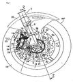
- Figs. 1-3 show the embodiment of the invention.
- Fig. 1 is a partially cutaway side view of a front wheel of a motorcycle and its vicinity
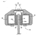
- Fig. 2 is a cross-sectional view taken along a line 2-2 in Fig. 1
- Fig. 3 is a cross-sectional view taken along a line 3-3 in Fig 1.
- a front fork 5 of the motorcycle has a pair of legs 6, 7 disposed on opposite sides of a front wheel WF.
- Each of the legs 6, 7 has an axle supporting portion 6a, 7a at its lower end, and an axle collar 8 and an axle 9 disposed through the axle collar 8 are fixedly disposed between the axle supporting portions 6a, 7a, with an axial position of the axle collar 8 and axle 9 fixed.
- the front wheel WF comprises a cylindrical hub 12 coaxially enclosing the axle collar 8 with a pair of ball bearings 10, 11 interposed between the hub 12 and the axle collar 8, and a rim 13 coaxially surrounding the hub 12, and a plurality of spokes 14 integrally connecting the hub 12 and the rim 13, and a tire 15 placed on the rim 13.
- a pair of mounting bosses 16, 17, which are separated in a vertical direction, are formed integrally with and continuously from the axle supporting portion 6a, 7a.
- Respective brake calipers 19 of a pair of disk brakes 18 for braking the front wheel WF are mounted on respective pairs of the mounting bosses 16, 17, with a mounting direction 20 of each brake caliper 19 along a radial direction of the front wheel WF.
- each of the disk brakes 18 comprises a brake disk 22 attached to an end of the hub 12 with a plurality of screw members 21, a pair of friction pads 23, 23 disposed on opposite sides of the brake disk 22, and the brake caliper 19 extending from one side of the disk brake 22 to the other side thereof over a circumference of the disk brake 22 to support the friction pads 23, 23.
- the brake caliper 19 comprises an acting portion and a reacting portion 25 that are connected to each other.
- each of the acting portion 24 and the reacting portion 25 there is slidably fitted a piston 26, so that metal backings 23a, 23a of the respective friction pads 23, 23 on the opposite sides of the brake disk 22 are pushed by the respective pistons 26 and thereby brought into frictional contact with the brake disk 22.
- the disk brake 18 constructed as described above is of radial mount type, and the acting portion 24 of its brake caliper 19 is fastened to the bosses 16, 17 with a pair of mounting bolts 27, 28 each having an axis along a radial direction of the front wheel WF.
- a pulser ring 30 made of a magnetic metal is held in contact with a central portion of an outer surface of the brake disk 22 of the disk brake 18 disposed on the right side of the front wheel WF.
- the pulser ring 30 is integrally fastened to a left side end of the hub 12 jointly with the brake disk 22, with the screw members 21, and the pulser ring 30 rotates with the front wheel WF.
- a multiplicity of protrusions 31 are formed at an outer circumference of an outer side of the pulser ring 31, with an equal spacing therebetween in the circumferential direction.
- a wheel speed sensor 32 which is a magnetic proximity sensor for detecting a speed of the front wheel WF by detecting the protrusions 31, is fastened to a support plate 33 with bolts 34 so as to oppose to the protrusions 31 with a small distance.
- the support plate 33 is substantially L-shaped and fastened with bolts 35 to the under surface of the mounting boss 17 as the lower one of the pair of mounting bosses 16, 17 formed at the right one 6 of the legs 6, 7 of the front fork 5, as disposed on the right side of the front wheel WF. That is, the wheel speed sensor 32 is disposed at the lower portion of the front fork 5 and on the right side of the front wheel WF, and attached, via the support plate 33, to the under surface of the lower one 17 of the mounting bosses 16, 17 that are disposed integrally with the lower portion of the right side of the front fork 5.
- the front wheel WF is covered by a front fender 36 from its upper side.
- a pair of attaching plates 37, 38 each having a protruding shape are formed integrally with a lower part of each of the legs 6, 7 of the front fork 5, and the front fender 36 is fastened to the two pairs of attaching plates 37, 38.
- the brake calipers 19 of the disk brakes 18 for braking the front wheel WF are respectively mounted on the mounting bosses 16, 17 at the lower portions of the respective legs 6, 7 of the front fork 5 pivotably supporting the front wheel WF, which are disposed on the opposite sides of the front wheel WF, with its mounting direction 20 along a radial direction of the front wheel WF.
- the wheel speed sensor 32 is attached via the support plate 33 to the mounting boss 17 disposed in the leg 6 of the right side.
- the wheel speed sensor 32 Since the wheel speed sensor 32 is attached to the mounting boss 17 which is disposed at the lower portion of the front fork 5 in order to mount the brake caliper 19 of the disk brake 18 of radial mount type thereon, the wheel speed sensor 32 can be disposed at a position which does not inhibit a replacement of the brake caliper 19, and which enables to omit the boss, stay or the like exclusively for the wheel speed sensor 32, facilitating the maintenance of the disk brake 18 and reducing the cost.
- axle supporting portions 6a, 7a are formed at the lower ends of the legs 6, 7 of the front fork 5, and the mounting bosses 16, 17 are formed integrally with and continuously from the respective axle supporting portions 6a, 7a, an exclusive member for mounting the brake caliper 19 of the disk brake 18 thereon can be omitted.
- wheel speed sensor 32 is attached to the mounting boss 17 formed integrally with and continuously from the axle supporting portion 6a of the right side, an exclusive member for attaching the wheel speed sensor thereto can be omitted.
- the number of members can be reduced.
- the wheel speed sensor 32 is attached to the under surface of the lower one 17 of the mounting bosses 16, 17, which are formed to be separated in a vertical direction on the right one 6 of the legs 6, 7 of the front fork 5, the space below the mounting boss 17 is efficiently utilized.
Landscapes
- Engineering & Computer Science (AREA)
- Mechanical Engineering (AREA)
- Braking Arrangements (AREA)
- Regulating Braking Force (AREA)
Abstract
Description
- 5
- front fork
- 6a
- axle supporting portion
- 16, 17
- mounting boss
- 18
- disk brake
- 19
- brake caliper
- 20
- mounting direction
- 32
- wheel speed sensor
- WF
- front wheel
Claims (3)
- A structure of attaching a wheel speed sensor in a motorcycle, in which a brake caliper (19) of a disk brake (18) for braking a front wheel (WF) is mounted on a mounting boss (17) disposed at a lower portion of a front fork (5) pivotably supporting the front wheel (WF), with a mounting direction (20) along a radial direction of the front wheel (WF),
characterized in that a wheel speed sensor (32) is attached to the mounting boss (17). - The structure of claim 1,
characterized in that the mounting boss (17) is formed integrally with and continuously from an axle supporting portion (6a) which is formed at a lower end of the front fork (5) to pivotably support the front wheel (WF). - The structure of claim 1 or 2,
characterized in that a pair of mounting bosses (16, 17), which are separated in a vertical direction, are formed at a lower portion of the front fork (5), and the wheel speed sensor (32) is attached to an under surface of the lower one (17) of the mounting bosses (16, 17).
Applications Claiming Priority (2)
| Application Number | Priority Date | Filing Date | Title |
|---|---|---|---|
| JP2004085371A JP4414257B2 (en) | 2004-03-23 | 2004-03-23 | Wheel speed sensor mounting structure for motorcycles |
| JP2004085371 | 2004-03-23 |
Publications (2)
| Publication Number | Publication Date |
|---|---|
| EP1580109A1 true EP1580109A1 (en) | 2005-09-28 |
| EP1580109B1 EP1580109B1 (en) | 2007-11-28 |
Family
ID=34858417
Family Applications (1)
| Application Number | Title | Priority Date | Filing Date |
|---|---|---|---|
| EP05002534A Ceased EP1580109B1 (en) | 2004-03-23 | 2005-02-07 | Structure of attaching wheel speed sensor in motorcycle |
Country Status (4)
| Country | Link |
|---|---|
| US (1) | US7322437B2 (en) |
| EP (1) | EP1580109B1 (en) |
| JP (1) | JP4414257B2 (en) |
| DE (1) | DE602005003495T2 (en) |
Cited By (5)
| Publication number | Priority date | Publication date | Assignee | Title |
|---|---|---|---|---|
| JP2013032051A (en) * | 2011-07-31 | 2013-02-14 | Honda Motor Co Ltd | Mounting structure of wheel speed sensor |
| EP2749465A1 (en) * | 2012-12-25 | 2014-07-02 | Honda Motor Co., Ltd. | Mounting structure of wheel speed sensor ring |
| CN106494558A (en) * | 2015-09-07 | 2017-03-15 | 铃木株式会社 | For installing the mounting structure of wheel speed sensor device |
| DE102007053339B4 (en) * | 2006-11-13 | 2020-10-01 | Honda Motor Co., Ltd. | Motorcycle wheel speed sensor mounting structure |
| US20220017175A1 (en) * | 2020-07-16 | 2022-01-20 | Shimano Inc. | Sensor wheel and disc brake apparatus |
Families Citing this family (21)
| Publication number | Priority date | Publication date | Assignee | Title |
|---|---|---|---|---|
| JP4520333B2 (en) * | 2005-03-09 | 2010-08-04 | 本田技研工業株式会社 | Vehicle speed sensor mounting structure |
| JP4648135B2 (en) * | 2005-09-06 | 2011-03-09 | 本田技研工業株式会社 | Motorcycle |
| NL1034435C2 (en) * | 2007-09-27 | 2009-03-30 | Accell Group N V | Bicycle, sensor, and method. |
| JP5198129B2 (en) * | 2008-04-18 | 2013-05-15 | 川崎重工業株式会社 | Wheel speed sensor mounting device |
| JP5990045B2 (en) * | 2012-06-26 | 2016-09-07 | 本田技研工業株式会社 | Saddle riding type vehicle |
| TWI479155B (en) * | 2013-03-29 | 2015-04-01 | Kwang Yang Motor Co | Locomotive wheel scale induction device |
| JP2015199477A (en) * | 2014-04-10 | 2015-11-12 | ヤマハ発動機株式会社 | Saddle riding vehicle |
| CN104908730B (en) * | 2015-06-24 | 2018-01-12 | 力帆实业(集团)股份有限公司 | Wheel speed sensor stent before riding-type motorcycle ABS |
| JP2017065533A (en) * | 2015-09-30 | 2017-04-06 | ヤマハ発動機株式会社 | vehicle |
| JP2017065532A (en) * | 2015-09-30 | 2017-04-06 | ヤマハ発動機株式会社 | vehicle |
| JP6148305B2 (en) * | 2015-09-30 | 2017-06-14 | 本田技研工業株式会社 | Saddle riding |
| DE102015120657B4 (en) * | 2015-11-27 | 2023-09-28 | Gustav Magenwirth Gmbh & Co. Kg | Bicycle |
| DE102015120656A1 (en) * | 2015-11-27 | 2017-06-01 | Gustav Magenwirth Gmbh & Co. Kg | wheel unit |
| JP6196345B1 (en) | 2016-03-15 | 2017-09-13 | 本田技研工業株式会社 | Wheel speed detection device |
| JP6683027B2 (en) * | 2016-06-14 | 2020-04-15 | スズキ株式会社 | Brake disc and speed sensor ring mounting structure |
| IT201600111381A1 (en) * | 2016-11-04 | 2018-05-04 | Piaggio & C Spa | SUPPORT STRUCTURE FOR SOUND WHEEL SENSOR |
| JP6720094B2 (en) * | 2017-01-13 | 2020-07-08 | 株式会社シマノ | Bicycle magnetic generator and disc brake adapter |
| DE102017110946A1 (en) * | 2017-05-19 | 2018-11-22 | Gustav Magenwirth Gmbh & Co. Kg | Wheel unit for a vehicle |
| BR112020000036B1 (en) * | 2017-09-27 | 2024-03-12 | Honda Motor Co., Ltd | STRUCTURE FOR VEHICLE FRONT PART TO ASSEMBLE |
| JP6736596B2 (en) * | 2018-03-16 | 2020-08-05 | 本田技研工業株式会社 | vehicle |
| JP7030081B2 (en) | 2019-06-27 | 2022-03-04 | 本田技研工業株式会社 | Front fork undercarriage of saddle-riding vehicle |
Citations (5)
| Publication number | Priority date | Publication date | Assignee | Title |
|---|---|---|---|---|
| JPH04191186A (en) * | 1990-11-26 | 1992-07-09 | Honda Motor Co Ltd | Speed sensor arrangement structure for motor-cycle |
| JPH0712149A (en) | 1993-06-28 | 1995-01-17 | Nissin Kogyo Kk | Vehicle disc brake caliper body mounting structure |
| JPH0717609U (en) | 1993-09-01 | 1995-03-31 | 忠良 早川 | Car body stabilizer |
| JP2002029395A (en) * | 2000-07-19 | 2002-01-29 | Honda Motor Co Ltd | Mounting structure of wheel speed detector |
| JP2003065369A (en) * | 2001-06-15 | 2003-03-05 | Tokico Ltd | Disc brake |
Family Cites Families (4)
| Publication number | Priority date | Publication date | Assignee | Title |
|---|---|---|---|---|
| JPH0717609A (en) | 1993-07-02 | 1995-01-20 | Murata Mach Ltd | Physical distribution system |
| JP2001165949A (en) * | 1999-09-30 | 2001-06-22 | Honda Motor Co Ltd | Wheel speed detector |
| JP4728618B2 (en) * | 2004-09-30 | 2011-07-20 | 本田技研工業株式会社 | Pulsar ring mounting structure |
| JP4520333B2 (en) * | 2005-03-09 | 2010-08-04 | 本田技研工業株式会社 | Vehicle speed sensor mounting structure |
-
2004
- 2004-03-23 JP JP2004085371A patent/JP4414257B2/en not_active Expired - Fee Related
-
2005
- 2005-02-07 DE DE602005003495T patent/DE602005003495T2/en not_active Expired - Lifetime
- 2005-02-07 EP EP05002534A patent/EP1580109B1/en not_active Ceased
- 2005-03-04 US US11/073,070 patent/US7322437B2/en not_active Expired - Lifetime
Patent Citations (6)
| Publication number | Priority date | Publication date | Assignee | Title |
|---|---|---|---|---|
| JPH04191186A (en) * | 1990-11-26 | 1992-07-09 | Honda Motor Co Ltd | Speed sensor arrangement structure for motor-cycle |
| JPH0712149A (en) | 1993-06-28 | 1995-01-17 | Nissin Kogyo Kk | Vehicle disc brake caliper body mounting structure |
| JPH0717609U (en) | 1993-09-01 | 1995-03-31 | 忠良 早川 | Car body stabilizer |
| JP2002029395A (en) * | 2000-07-19 | 2002-01-29 | Honda Motor Co Ltd | Mounting structure of wheel speed detector |
| ES2192946A1 (en) * | 2000-07-19 | 2003-10-16 | Honda Motor Co Ltd | Wheel speed detector mounting structure |
| JP2003065369A (en) * | 2001-06-15 | 2003-03-05 | Tokico Ltd | Disc brake |
Non-Patent Citations (4)
| Title |
|---|
| BIKE, TOWER PUBLISHING SERVICES LTD, LEICESTERSHIRE, GB, no. 367, 8 October 2003 (2003-10-08), pages 26 - 28, XP002372069, ISSN: 0140-4547 * |
| PATENT ABSTRACTS OF JAPAN vol. 016, no. 519 (M - 1330) 26 October 1992 (1992-10-26) * |
| PATENT ABSTRACTS OF JAPAN vol. 2002, no. 05 3 May 2002 (2002-05-03) * |
| PATENT ABSTRACTS OF JAPAN vol. 2003, no. 07 3 July 2003 (2003-07-03) * |
Cited By (7)
| Publication number | Priority date | Publication date | Assignee | Title |
|---|---|---|---|---|
| DE102007053339B4 (en) * | 2006-11-13 | 2020-10-01 | Honda Motor Co., Ltd. | Motorcycle wheel speed sensor mounting structure |
| JP2013032051A (en) * | 2011-07-31 | 2013-02-14 | Honda Motor Co Ltd | Mounting structure of wheel speed sensor |
| EP2749465A1 (en) * | 2012-12-25 | 2014-07-02 | Honda Motor Co., Ltd. | Mounting structure of wheel speed sensor ring |
| CN106494558A (en) * | 2015-09-07 | 2017-03-15 | 铃木株式会社 | For installing the mounting structure of wheel speed sensor device |
| CN106494558B (en) * | 2015-09-07 | 2019-07-12 | 铃木株式会社 | For installing the mounting structure of wheel speed sensor device |
| US20220017175A1 (en) * | 2020-07-16 | 2022-01-20 | Shimano Inc. | Sensor wheel and disc brake apparatus |
| US11524741B2 (en) * | 2020-07-16 | 2022-12-13 | Shimano Inc. | Sensor wheel and disc brake apparatus |
Also Published As
| Publication number | Publication date |
|---|---|
| DE602005003495D1 (en) | 2008-01-10 |
| JP2005271666A (en) | 2005-10-06 |
| US7322437B2 (en) | 2008-01-29 |
| JP4414257B2 (en) | 2010-02-10 |
| EP1580109B1 (en) | 2007-11-28 |
| DE602005003495T2 (en) | 2008-11-27 |
| US20050247499A1 (en) | 2005-11-10 |
Similar Documents
| Publication | Publication Date | Title |
|---|---|---|
| EP1580109A1 (en) | Structure of attaching wheel speed sensor in motorcycle | |
| JP3732182B2 (en) | Bicycle hub | |
| US3709561A (en) | Brake and wheel assembly for motorcycles and the like | |
| US7661771B2 (en) | Speed sensor fitting structure | |
| CN107499440B (en) | Mounting structure of brake disc and speed sensor ring | |
| JP5654920B2 (en) | Wheel assembly structure for saddle-ride type vehicles | |
| AU2016237585B2 (en) | Wheel speed detecting device, and ring to be detected | |
| US20080257663A1 (en) | Brake disc | |
| CN109383687B (en) | Disc brake rotor assembly and brake system | |
| JP6794238B2 (en) | Caliper for opposed piston type disc brake | |
| ITTO970231A1 (en) | INTEGRATED GROUP WHEEL AND HUB-WHEEL, IN PARTICULAR FOR A VEHICLE. | |
| JP2012232658A (en) | Vehicle wheel | |
| US10288639B2 (en) | Wheel speed detecting device | |
| JPH08133154A (en) | Wheel speed detection device for motorcycles | |
| CN104583067B (en) | motorcycle | |
| JP2008261412A (en) | Drum brakes, brake linings, and saddle riding type vehicles | |
| US4884663A (en) | Device for supporting and attaching a disk brake caliper | |
| JP2787016B2 (en) | Disc brake mounting structure for scooter type vehicle | |
| JP6966985B2 (en) | Wheel cover structure | |
| JPS5943187Y2 (en) | disc brake device | |
| EP1762744B1 (en) | Drum brake and straddle-type vehicle | |
| JPH0747627Y2 (en) | Vehicle brake disc caliper body mounting structure | |
| JP2024112048A (en) | Disc brake device and saddle-type vehicle | |
| JP2023134008A (en) | floating brake disc | |
| JP6290682B2 (en) | Vehicle speed detection device |
Legal Events
| Date | Code | Title | Description |
|---|---|---|---|
| PUAI | Public reference made under article 153(3) epc to a published international application that has entered the european phase |
Free format text: ORIGINAL CODE: 0009012 |
|
| 17P | Request for examination filed |
Effective date: 20050207 |
|
| AK | Designated contracting states |
Kind code of ref document: A1 Designated state(s): AT BE BG CH CY CZ DE DK EE ES FI FR GB GR HU IE IS IT LI LT LU MC NL PL PT RO SE SI SK TR |
|
| AX | Request for extension of the european patent |
Extension state: AL BA HR LV MK YU |
|
| AKX | Designation fees paid |
Designated state(s): DE FR GB |
|
| 17Q | First examination report despatched |
Effective date: 20060817 |
|
| GRAP | Despatch of communication of intention to grant a patent |
Free format text: ORIGINAL CODE: EPIDOSNIGR1 |
|
| GRAS | Grant fee paid |
Free format text: ORIGINAL CODE: EPIDOSNIGR3 |
|
| GRAA | (expected) grant |
Free format text: ORIGINAL CODE: 0009210 |
|
| AK | Designated contracting states |
Kind code of ref document: B1 Designated state(s): DE FR GB |
|
| REG | Reference to a national code |
Ref country code: GB Ref legal event code: FG4D |
|
| REF | Corresponds to: |
Ref document number: 602005003495 Country of ref document: DE Date of ref document: 20080110 Kind code of ref document: P |
|
| ET | Fr: translation filed | ||
| PLBE | No opposition filed within time limit |
Free format text: ORIGINAL CODE: 0009261 |
|
| STAA | Information on the status of an ep patent application or granted ep patent |
Free format text: STATUS: NO OPPOSITION FILED WITHIN TIME LIMIT |
|
| 26N | No opposition filed |
Effective date: 20080829 |
|
| REG | Reference to a national code |
Ref country code: DE Ref legal event code: R084 Ref document number: 602005003495 Country of ref document: DE |
|
| REG | Reference to a national code |
Ref country code: GB Ref legal event code: 746 Effective date: 20141114 |
|
| REG | Reference to a national code |
Ref country code: DE Ref legal event code: R084 Ref document number: 602005003495 Country of ref document: DE Effective date: 20141120 |
|
| REG | Reference to a national code |
Ref country code: FR Ref legal event code: PLFP Year of fee payment: 12 |
|
| REG | Reference to a national code |
Ref country code: FR Ref legal event code: PLFP Year of fee payment: 13 |
|
| REG | Reference to a national code |
Ref country code: DE Ref legal event code: R085 Ref document number: 602005003495 Country of ref document: DE |
|
| REG | Reference to a national code |
Ref country code: GB Ref legal event code: S47 Free format text: CANCELLATION OF ENTRY; APPLICATION FOR CANCELLATION OF ENTRY ON THE REGISTER OF A LICENCE OF RIGHT FILED ON 25 AUGUST 2017 |
|
| REG | Reference to a national code |
Ref country code: FR Ref legal event code: PLFP Year of fee payment: 14 |
|
| REG | Reference to a national code |
Ref country code: GB Ref legal event code: S47 Free format text: ENTRY CANCELLED; NOTICE IS HEREBY GIVEN THAT THE LICENCE OF RIGHT ENTRY ON THE REGISTER FOR THE FOLLOWING PATENT WAS CANCELLED ON 24 JANUARY 2018 HONDA MOTOR CO., LTD STRUCTURE OF ATTACHING WHEEL SPEED SENSOR IN MOTORCYCLE |
|
| PGFP | Annual fee paid to national office [announced via postgrant information from national office to epo] |
Ref country code: GB Payment date: 20180207 Year of fee payment: 14 |
|
| PGFP | Annual fee paid to national office [announced via postgrant information from national office to epo] |
Ref country code: FR Payment date: 20180111 Year of fee payment: 14 |
|
| GBPC | Gb: european patent ceased through non-payment of renewal fee |
Effective date: 20190207 |
|
| PG25 | Lapsed in a contracting state [announced via postgrant information from national office to epo] |
Ref country code: GB Free format text: LAPSE BECAUSE OF NON-PAYMENT OF DUE FEES Effective date: 20190207 |
|
| PG25 | Lapsed in a contracting state [announced via postgrant information from national office to epo] |
Ref country code: FR Free format text: LAPSE BECAUSE OF NON-PAYMENT OF DUE FEES Effective date: 20190228 |
|
| PGFP | Annual fee paid to national office [announced via postgrant information from national office to epo] |
Ref country code: DE Payment date: 20210126 Year of fee payment: 17 |
|
| REG | Reference to a national code |
Ref country code: DE Ref legal event code: R119 Ref document number: 602005003495 Country of ref document: DE |
|
| PG25 | Lapsed in a contracting state [announced via postgrant information from national office to epo] |
Ref country code: DE Free format text: LAPSE BECAUSE OF NON-PAYMENT OF DUE FEES Effective date: 20220901 |