EP1580066B1 - Baufahrzeug zur Bodenbearbeitung mit einem Rückspiegelpaar - Google Patents
Baufahrzeug zur Bodenbearbeitung mit einem Rückspiegelpaar Download PDFInfo
- Publication number
- EP1580066B1 EP1580066B1 EP05100503A EP05100503A EP1580066B1 EP 1580066 B1 EP1580066 B1 EP 1580066B1 EP 05100503 A EP05100503 A EP 05100503A EP 05100503 A EP05100503 A EP 05100503A EP 1580066 B1 EP1580066 B1 EP 1580066B1
- Authority
- EP
- European Patent Office
- Prior art keywords
- pair
- rearview mirrors
- driver
- construction vehicle
- seat
- Prior art date
- Legal status (The legal status is an assumption and is not a legal conclusion. Google has not performed a legal analysis and makes no representation as to the accuracy of the status listed.)
- Expired - Lifetime
Links
- 238000010276 construction Methods 0.000 title claims description 35
- 239000002689 soil Substances 0.000 title description 2
- 230000001360 synchronised effect Effects 0.000 abstract description 2
- 230000005540 biological transmission Effects 0.000 description 15
- 238000001514 detection method Methods 0.000 description 7
- 238000006073 displacement reaction Methods 0.000 description 4
- 238000003971 tillage Methods 0.000 description 3
- 230000033001 locomotion Effects 0.000 description 2
- 238000000034 method Methods 0.000 description 2
Images

Classifications
-
- B—PERFORMING OPERATIONS; TRANSPORTING
- B60—VEHICLES IN GENERAL
- B60N—SEATS SPECIALLY ADAPTED FOR VEHICLES; VEHICLE PASSENGER ACCOMMODATION NOT OTHERWISE PROVIDED FOR
- B60N2/00—Seats specially adapted for vehicles; Arrangement or mounting of seats in vehicles
- B60N2/02—Seats specially adapted for vehicles; Arrangement or mounting of seats in vehicles the seat or part thereof being movable, e.g. adjustable
- B60N2/04—Seats specially adapted for vehicles; Arrangement or mounting of seats in vehicles the seat or part thereof being movable, e.g. adjustable the whole seat being movable
- B60N2/06—Seats specially adapted for vehicles; Arrangement or mounting of seats in vehicles the seat or part thereof being movable, e.g. adjustable the whole seat being movable slidable
- B60N2/062—Seats specially adapted for vehicles; Arrangement or mounting of seats in vehicles the seat or part thereof being movable, e.g. adjustable the whole seat being movable slidable transversally slidable
-
- B—PERFORMING OPERATIONS; TRANSPORTING
- B60—VEHICLES IN GENERAL
- B60N—SEATS SPECIALLY ADAPTED FOR VEHICLES; VEHICLE PASSENGER ACCOMMODATION NOT OTHERWISE PROVIDED FOR
- B60N2/00—Seats specially adapted for vehicles; Arrangement or mounting of seats in vehicles
- B60N2/02—Seats specially adapted for vehicles; Arrangement or mounting of seats in vehicles the seat or part thereof being movable, e.g. adjustable
- B60N2/04—Seats specially adapted for vehicles; Arrangement or mounting of seats in vehicles the seat or part thereof being movable, e.g. adjustable the whole seat being movable
- B60N2/14—Seats specially adapted for vehicles; Arrangement or mounting of seats in vehicles the seat or part thereof being movable, e.g. adjustable the whole seat being movable rotatable, e.g. to permit easy access
-
- B—PERFORMING OPERATIONS; TRANSPORTING
- B60—VEHICLES IN GENERAL
- B60N—SEATS SPECIALLY ADAPTED FOR VEHICLES; VEHICLE PASSENGER ACCOMMODATION NOT OTHERWISE PROVIDED FOR
- B60N2/00—Seats specially adapted for vehicles; Arrangement or mounting of seats in vehicles
- B60N2/24—Seats specially adapted for vehicles; Arrangement or mounting of seats in vehicles for particular purposes or particular vehicles
-
- E—FIXED CONSTRUCTIONS
- E01—CONSTRUCTION OF ROADS, RAILWAYS, OR BRIDGES
- E01C—CONSTRUCTION OF, OR SURFACES FOR, ROADS, SPORTS GROUNDS, OR THE LIKE; MACHINES OR AUXILIARY TOOLS FOR CONSTRUCTION OR REPAIR
- E01C19/00—Machines, tools or auxiliary devices for preparing or distributing paving materials, for working the placed materials, or for forming, consolidating, or finishing the paving
- E01C19/22—Machines, tools or auxiliary devices for preparing or distributing paving materials, for working the placed materials, or for forming, consolidating, or finishing the paving for consolidating or finishing laid-down unset materials
- E01C19/23—Rollers therefor; Such rollers usable also for compacting soil
- E01C19/26—Rollers therefor; Such rollers usable also for compacting soil self-propelled or fitted to road vehicles
-
- E—FIXED CONSTRUCTIONS
- E01—CONSTRUCTION OF ROADS, RAILWAYS, OR BRIDGES
- E01C—CONSTRUCTION OF, OR SURFACES FOR, ROADS, SPORTS GROUNDS, OR THE LIKE; MACHINES OR AUXILIARY TOOLS FOR CONSTRUCTION OR REPAIR
- E01C2301/00—Machine characteristics, parts or accessories not otherwise provided for
- E01C2301/30—Cabin details
Definitions
- the invention relates to a construction vehicle according to the preamble of claim 1 and a pair of rearview mirrors according to the preamble of claim 1.
- construction machines for soil tillage, especially in road rollers, it is often necessary that is driven with an exact lateral distance to, for example, a curb, a house or an already processed ground surface.
- construction machines are known in which the sitting position can be moved to one of the sides of the construction vehicle.
- the driver adjusts the rearview mirror of the vehicle to its current seating position and height before driving. If the seated position of the driver is shifted to the left or right during the working process, the rearview mirrors are no longer aligned with the current seating position. The driver must therefore adjust the rearview mirror again to the current seating position.
- a construction vehicle with a horizontally laterally movable control station is known from DE 198 13 474.
- DE 32 38 900 shows a mechanically coupled to an adjustable vehicle seat rearview mirror.
- adjusting the angular position of the rear-view mirror of the pair of rear-view mirror depending on the driver's seat position is advantageously allows the driver to change the seat position orthogonal to the direction of travel along the vehicle width, without having to make a re-adjustment of the rearview mirror to its seating position , Further, since the rearview mirrors of the rearview mirror pair are mechanically coupled to each other, only a single adjusting device for changing the angular position of the rearview mirror of the pair of rearview mirrors is necessary and a synchronous adjustment is possible in a particularly simple manner.
- the rear-view mirror pair is arranged as a front pair of rear-view mirrors in the direction of travel of the construction vehicle in front of the driver.
- a further pair of rear-view mirrors is arranged behind the driver as a rear pair of rear-view mirrors in the direction of travel.
- the sitting position of the driver can be detected via a detection device. As a result, the exact sitting position of the driver can be determined and, depending on this, an adjustment of the rearview mirror of the pair of rearview mirrors is undertaken.
- a driver's seat is preferably displaceable orthogonal to the direction of travel along the vehicle width.
- a driver's cab in which the driver's seat is displaceable orthogonal to the direction of travel along the vehicle width.
- the detection device can be arranged on the driver's seat and / or on the driver's cab.
- a direct detection of the driver's seat position is thus possible with the aid of the position of the driver's seat and / or the driver's cab.
- the detection device may consist of a sensor which sends a signal to the adjusting device of the pair of rearview mirrors.
- the rear-view mirror pair is mechanically coupled via a cable transmission.
- a cable transmission makes it possible that a single adjustment can make the angular adjustment of the rearview mirror.
- a cable transmission is structurally simple to implement.
- the adjusting device of the rear-view mirror pair preferably comprises a drive unit and a control device.
- the drive unit may consist of an electric motor.
- control device consists of an electronic unit which controls the drive unit as a function of the signal of the sensor. This makes it particularly easy to control the drive unit as a function of the signal of the sensor and thus as a function of the driver's seat position to make an angular adjustment of the mirror pair.
- the drive unit can directly drive the cable transmission for adjusting the angular position of the rearview mirror of the mirror pair. This makes it possible in a structurally simple way the adjustment of the angular position of the rearview mirror of the pair of rearview mirrors make.
- the driver's seat is rotatably arranged for a reversal of the direction of travel. This allows the driver to drive the vehicle in the reverse direction in a comfortable manner. In addition, a safe driving in the opposite direction of travel is made possible by the arrangement of the rear rearview mirror.
- the rear pair of rear-view mirrors can be aligned with the current seating position when the driver's seat is rotated.
- the drive unit of the rear pair of rearview mirrors is activated only upon rotation of the driver's seat and makes the adjustment of the angular position of the rearview mirror of the rear pair of rearview mirror. This avoids that the rear-view mirror located behind the driver while driving, which he does not use at this time, are constantly being moved when the seat position changes. The wear of the adjusting the rear-view mirror is minimized.
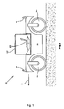
- Fig. 1 is a side view of a construction vehicle according to the invention
- Fig. 2 is a schematic plan view of an inventive construction vehicle
- a construction vehicle 1 for tillage in the form of a road roller is shown schematically.
- a mounted on two rollers 21 vehicle frame 12 carries a driver's cab 17.
- the direction of travel of the road roller is indicated by the arrow with the reference numeral 3.
- only one front pair of rearview mirrors 4, 5 is arranged on the construction vehicle 1.
- a driver's seat 15 is arranged in the driver's cab 17, a driver's seat 15 is arranged.
- the driver's seat 15 can be pushed back and forth orthogonally to the direction of travel along the vehicle width, as indicated in FIG. 2 by a double arrow.
- the entire vehicle cabin 17 can also be displaced orthogonally to the direction of travel along the vehicle width, as indicated in FIG. 2 likewise by a double arrow.
- the displacement is not limited by the extent of the vehicle frame in width, but the vehicle cabin 17 can be moved so far that it extends laterally beyond the vehicle frame 12.
- the driver's seat position 9 can be changed.
- a detection device 11 is attached in the form of a sensor.
- Another detection device 13, which may also be a sensor, is attached to the driver's cab 17. The detecting means 11 and 13 detect the displacement of the driver's seat 15 and the cab 17, thus determining the driver's seating position 9.
- either only the driver's seat 15 or the driver's cab 17 are arranged displaceably, so that accordingly only the detecting device 11 in the embodiment with displaceable driver's seat 15 and the detecting device 13 in the embodiment with movable cab 17 for determination seat position 9 of the driver is necessary.
- the rear-view mirror pairs 4, 5 and 6, 7 are each connected to one another via a cable transmission 19.
- An adjusting device 2 is arranged on the cable transmission 19 and serves to adjust the cable transmission 19 and thus the adjustment of the rear-view mirror pairs 4,5 and 6,7.
- the adjusting device 2 comprises a control device 23, which may be an electronic unit, and a drive unit 22.
- the cable transmission 19 each only from a single cable connection to the individual rear-view mirror pairs of mirrors 4.5 and 6.7.
- the cable transmission 19 is replaced by a rod gear.
- the controller 23 sets the drive unit 22 in operation, so that via the cable transmission 19 the angular position of Rear-view mirror of the corresponding rear-view mirror pair 4, 5 and 6, 7 changed and adapted to the seating position 9 of the driver.
- the driver's seat 15 can be turned completely, so that when reversing the direction of travel 3 in the opposite direction, the driver can always see in the current direction of travel.
- the driver can use the rear-view mirror pair 6, 7 in the embodiment shown in FIG.
- the angular positions of the rear-view mirrors of both pairs of rear-view mirrors are always adapted synchronously and steplessly to the current seating position 9, or guided when the seat position 9 is changed.
- only the respective used by the driver rearview mirror of the pair of rearview mirror 4.5 are carried on changing the seat position 9.
- the previously unused rearview mirrors 6, 7 are then adapted to the seated position 9.
Landscapes
- Engineering & Computer Science (AREA)
- Aviation & Aerospace Engineering (AREA)
- Transportation (AREA)
- Mechanical Engineering (AREA)
- Architecture (AREA)
- Civil Engineering (AREA)
- Structural Engineering (AREA)
- Rear-View Mirror Devices That Are Mounted On The Exterior Of The Vehicle (AREA)
- Soil Working Implements (AREA)
- Guiding Agricultural Machines (AREA)
- Cultivation Receptacles Or Flower-Pots, Or Pots For Seedlings (AREA)
- Cultivation Of Plants (AREA)
Description
- Die Erfindung betrifft ein Baufahrzeug nach dem Oberbegriff des Anspruchs 1 sowie ein Rückspiegelpaar nach dem Oberbegriff des Anspruchs 1.
- Bei Baumaschinen zur Bodenbearbeitung, insbesondere bei Straßenwalzen, ist es häufig erforderlich, dass mit einem exakten Seitenabstand zu beispielsweise einer Bordsteinkante, einem Haus oder einer bereits bearbeiteten Bodenfläche gefahren wird. Damit ein Fahrer der Baumaschine diesen Seitenabstand besser erkennen und einhalten kann, sind Baumaschinen bekannt, bei denen die Sitzposition zu einer der Seiten des Baufahrzeuges verschoben werden kann.
- Um die hinter dem Fahrzeug befindliche Gegenstände zu erkennen, stellt der Fahrer vor der Fahrt die Rückspiegel des Fahrzeuges auf seine aktuelle Sitzposition und Körpergröße ein. Wird während des Arbeitsvorganges die Sitzposition des Fahrers nach links oder rechts verschoben, sind die Rückspiegel nicht mehr auf die aktuelle Sitzposition ausgerichtet. Der Fahrer muss daher die Rückspiegel erneut auf die aktuelle Sitzposition einstellen.
- Da das Einstellen der Sitzposition aus Sicherheitsgründen nicht während der Fahrt geschehen soll, muss der Fahrer das Baufahrzeug anhalten, um die Rückspiegel einzustellen. Somit ist dieser Vorgang zeitaufwändig und unwirtschaftlich. Ferner kann es vorkommen, dass der Fahrer, um den Zeitaufwand zu minimieren, auf das Verändern der Sitzposition verzichtet, was ein ungenaues Arbeiten zur Folge hat, oder die Einstellung der Rückspiegel nach Veränderung der Sitzposition nicht vornimmt, so dass die Arbeitssicherheit gefährdet ist, da der Fahrer hinter dem Fahrzeug befindliche Gegenstände nicht sehen kann.
- Ein Baufahrzeug mit einem horizontal seitlich verschiebbaren Fahrstand ist aus der DE 198 13 474 bekannt. Die DE 32 38 900 zeigt einen mechanisch an einen verstellbaren Fahrzeugsitz gekoppelten Rückblickspiegel.
- Es ist daher die Aufgabe der vorliegenden Erfindung, ein Baufahrzeug zur Bodenbearbeitung sowie ein Rückspiegelpaar für ein Baufahrzeug der eingangs genannten Art derart weiterzubilden, dass die oben genannten Nachteile vermieden werden und eine Rückspiegeleinstellung bei Veränderung der Sitzposition des Fahrers auf eine einfache Art und Weise ermöglicht wird.
- Zur Lösung der Aufgabe dienen die Merkmale des Anspruchs 1 bzw. 16.
- Durch eine Verstellung der Winkelposition der Rückspiegel des Rückspiegelpaares in Abhängigkeit der Sitzposition des Fahrers wird in vorteilhafter Weise ermöglicht, dass der Fahrer die Sitzposition orthogonal zur Fahrtrichtung in entlang der Fahrzeugbreite verändern kann, ohne dass er dazu eine erneute Einstellung der Rückspiegel auf seine Sitzposition vornehmen muss. Da ferner die Rückspiegel des Rückspiegelpaares mechanisch miteinander gekoppelt sind, ist nur eine einzige Verstelleinrichtung zur Änderung der Winkelposition der Rückspiegel des Rückspiegelpaares notwendig und ein synchrones Verstellen ist auf eine besonders einfache Art und Weise möglich.
- Vorzugsweise ist vorgesehen, dass das Rückspiegelpaar als ein vorderes Rückspiegelpaar in Fahrtrichtung des Baufahrzeuges vor dem Fahrer angeordnet ist.
- In einer bevorzugten Ausführungsform ist ein weiteres Rückspiegelpaar als ein hinteres Rückspiegelpaar in Fahrtrichtung hinter dem Fahrer angeordnet.
- Die Sitzposition des Fahrers kann über eine Detektiereinrichtung detektiert werden. Dadurch kann die genaue Sitzposition des Fahrers festgestellt werden und in Abhängigkeit davon eine Verstellung der Rückspiegel des Rückspiegelpaares vorgenommen werden.
- Zur Veränderung der Sitzposition des Fahrers ist vorzugsweise ein Fahrersitz orthogonal zur Fahrtrichtung entlang der Fahrzeugbreite verschiebbar. Alternativ oder zusätzlich ist eine Fahrerkabine, in der sich der Fahrersitz befindet, orthogonal zur Fahrtrichtung entlang der Fahrzeugbreite verschiebbar.
- Auf diese Weise ist es möglich, die Sitzposition des Fahrers auf eine einfache Art und Weise zu verändern.
- Je nach Ausführungsbeispiel kann die Detektiereinrichtung an dem Fahrersitz und/oder an der Fahrerkabine angeordnet sein. Eine direkte Detektierung der Sitzposition des Fahrers ist somit mit Hilfe der Position des Fahrersitzes und/oder der Fahrerkabine auf möglich.
- Die Detektiereinrichtung kann aus einem Sensor bestehen, der ein Signal an die Verstelleinrichtung des Rückspiegelpaares sendet.
- Vorzugsweise ist vorgesehen, dass das Rückspiegelpaar über ein Seilzuggetriebe mechanisch gekoppelt ist. Ein Seilzuggetriebe ermöglicht es, dass eine einzige Verstelleinrichtung die Winkelverstellung der Rückspiegel vornehmen kann. Darüber hinaus ist ein Seilzuggetriebe konstruktiv einfach zu verwirklichen.
- Die Verstelleinrichtung des Rückspiegelpaars umfasst vorzugsweise eine Antriebseinheit und eine Steuereinrichtung. Dabei kann die Antriebseinheit aus einem Elektromotor bestehen.
- Vorzugsweise ist vorgesehen, dass die Steuereinrichtung aus einer Elektronikeinheit besteht, die die Antriebseinheit in Abhängigkeit des Signals des Sensors steuert. Dadurch ist es besonders einfach möglich, die Antriebseinheit in Abhängigkeit des Signals des Sensors und somit in Abhängigkeit der Sitzposition des Fahrers zu steuern, um eine Winkelverstellung des Rückspiegelpaares vorzunehmen.
- Die Antriebseinheit kann das Seilzuggetriebe zur Verstellung der Winkelposition der Rückspiegel des Rückspiegelpaares direkt antreiben. Dadurch ist es möglich auf eine konstruktiv einfache Art und Weise die Verstellung der Winkelposition der Rückspiegel des Rückspiegelpaares vorzunehmen.
- In einem besonders bevorzugten Ausführungsform, ist der Fahrersitz für eine Umkehr der Fahrtrichtung drehbar angeordnet. Dadurch kann der Fahrer auf eine bequemen Art und Weise das Fahrzeug bei umgekehrter Fahrtrichtung fahren. Darüber hinaus wird durch die Anordnung der hinteren Rückspiegel ein sicheres Fahren bei umgekehrter Fahrtrichtung ermöglicht.
- Bei einem Ausführungsbeispiel ist vorgesehen, dass das hintere Rückspiegelpaar bei Drehung des Fahrersitzes auf die aktuelle Sitzposition ausrichtbar ist. Somit wird die Antriebseinheit des hinteren Rückspiegelpaares erst bei Drehung des Fahrersitzes aktiviert und nimmt die Verstellung der Winkelposition der Rückspiegel des hinteren Rückspiegelpaares vor. Dadurch wird vermieden, dass die während der Fahrt hinter dem Fahrer befindlichen Rückspiegel, die er zu diesem Zeitpunkt nicht benutzt, bei Veränderung der Sitzposition ständig bewegt werden. Der Verschleiß der Verstelleinrichtung der Rückspiegelpaare wird dadurch minimiert.
- Im folgenden wird unter Bezugnahme auf die Figuren die Erfindung näher erläutert.
- Es zeigen:
- Fig. 1 eine Seitenansicht eines erfindungsgemäßen Baufahrzeuges
- Fig. 2 eine schematische Draufsicht auf ein erfindungsgemäßes Baufahrzeug
- In Fig. 1 ist ein Baufahrzeug 1 zur Bodenbearbeitung in Form einer Straßenwalze schematisch dargestellt. Ein auf zwei Walzen 21 gelagerter Fahrzeugrahmen 12 trägt eine Fahrerkabine 17. Die Fahrtrichtung der Straßenwalze ist durch den Pfeil mit dem Bezugszeichen 3 angedeutet.
- Gemäß Fig. 2 ist in Fahrtrichtung 3 vor der Fahrerkabine 17 ist ein vorderes Rückspiegelpaar 4,5 angeordnet. Die Rückspiegel des vorderen Rückspiegelpaares 4,5 sind an den Seiten des Fahrzeugrahmens 12 angeordnet. In Fahrtrichtung 3 hinter der Fahrerkabine 17 ist ein weiteres Rückspiegelpaar 6, 7 in gleicher Art und Weise angeordnet.
- In einer nicht dargestellten Ausführungsform ist an dem Baufahrzeug 1 nur ein vorderes Rückspiegelpaar 4,5 angeordnet.
- In der Fahrerkabine 17 ist ein Fahrersitz 15 angeordnet. Der Fahrersitz 15 kann orthogonal zur Fahrtrichtung entlang der Fahrzeugbreite hin- und hergeschoben werden, wie in der Fig. 2 durch einen Doppelfeil angedeutet. Zusätzlich oder alternativ zu dem Verschieben des Fahrersitzes 15 kann auch die gesamte Fahrzeugkabine 17 orthogonal zur Fahrtrichtung entlang der Fahrzeugbreite verschoben werden, wie in Fig. 2 ebenfalls durch einen Doppelpfeil angedeutet. Bei dem Verschieben der Fahrerkabine 17 ist der Verschiebeweg nicht durch die Erstreckung des Fahrzeugsrahmens in der Breite beschränkt, sondern die Fahrzeugkabine 17 kann so weit verschoben werden, dass sie seitlich über dem Fahrzeugrahmen 12 hinausragt.
- Durch das Verschieben des Fahrersitzes 15 und/oder der Fahrerkabine 17 kann die Sitzposition 9 des Fahrers verändert werden. An dem Fahrersitz 15 ist eine Detektiereinrichtung 11 in Form eines Sensors befestigt. Eine weitere Detektiereinrichtung 13, die ebenfalls ein Sensor sein kann, ist an der Fahrerkabine 17 befestigt. Die Detektiereinrichtungen 11 und 13 detektieren die Verschiebung von dem Fahrersitz 15 und von der Kabine 17 und bestimmen auf diese Weise die Sitzposition 9 des Fahrers.
- In zwei nicht dargestellten Ausführungsbeispielen sind entweder nur der Fahrersitz 15 oder die Fahrerkabine 17 verschiebbar angeordnet, so dass entsprechend nur die Detektiereinrichtung 11 bei dem Ausführungsbeispiel mit verschiebbarem Fahrersitz 15 bzw. die Detektiereinrichtung 13 bei dem Ausführungsbeispiel mit verschiebbarer Fahrerkabine 17 zur Bestimmung der Sitzposition 9 des Fahrers notwendig ist.
- Die Rückspiegelpaare 4,5 bzw. 6,7 sind jeweils über ein Seilzuggetriebe 19 miteinander verbunden.
- Eine Verstelleinrichtung 2 ist an dem Seilzuggetriebe 19 angeordnet und dient der Verstellung des Seilzuggetriebes 19 und somit der Verstellung der Rückspiegelpaare 4,5 bzw. 6,7. Die Verstelleinrichtung 2 umfasst eine Steuereinrichtung 23, die eine Elektronikeinheit sein kann, sowie eine Antriebseinheit 22. Die Antriebseinheit 22, die beispielsweise aus einem Elektromotor bestehen kann, treibt das Seilzuggetriebe 19 an. Im dargestellten Ausführungsbeispiel besteht das Seilzuggetriebe 19 jeweils nur aus einer einzigen Seilverbindung zu den einzelnen Rückspiegeln der Rückspiegelpaare 4,5 bzw. 6,7. Wenn bei Betätigung der Verstelleinrichtung zur Veränderung der Winkelposition der einzelnen Rückspiegel der Rückspiegelpaare 4,5 bzw. 6,7 das Seilzuggetriebe 19 gezogen wird, wird gleichzeitig eine nicht dargestellte Feder vorgespannt, die bei Bewegungsumkehr des Seilzuggetriebes 19 und entsprechender Umkehr der Winkelverstellbewegung der Rückspiegel entspannt wird und den benötigten Zug auf das Seilzuggetriebe 19 ausübt.
- Alternativ ist jedoch auch ein Seilzuggetriebe 19 mit einer doppelten Seilzugverbindung zu den entsprechenden Rückspiegeln der Rückspiegelpaare 4,5 bzw. 6,7 möglich, durch die auf die Feder verzichtet werden kann.
- In einem nicht dargestellten Ausführungsbeispiel wird das Seilzuggetriebe 19 durch ein Stangengetriebe ersetzt.
- Bei Veränderung der Sitzposition 9 durch das Verschieben des Fahrersitzes 15 und/oder der Fahrerkabine 17 detektiert die Detektiereinheit 11 bzw. 13 die Verschiebebewegung und übermittelt ein Signal an die Steuereinrichtung 23. Die Steuereinrichtung 23 setzt die Antriebseinheit 22 in Betrieb, so dass über das Seilzuggetriebe 19 die Winkelposition der Rückspiegel des entsprechenden Rückspiegelpaares 4, 5 bzw. 6, 7 verändert und an die Sitzposition 9 des Fahrers angepasst wird.
- Der Fahrersitz 15 kann komplett gedreht werden, so dass bei Umkehr der Fahrtrichtung 3 in entgegengesetzter Richtung der Fahrer stets in die aktuelle Fahrtrichtung sehen kann. Nach einer Drehung des Fahrersitzes 15 um 180° kann der Fahrer in dem in Fig. 2 dargestellten Ausführungsbeispiel das Rückspiegelpaar 6, 7 nutzen. In dem in Fig. 2 dargestellten Ausführungsbeispiel werden die Winkelpositionen der Rückspiegel von beiden Rückspiegelpaaren stets synchron und stufenlos an die aktuelle Sitzposition 9 angepasst, bzw. bei Veränderung der Sitzposition 9 geführt. In einem alternativen nicht dargestellten Ausführungsbeispiel werden nur die jeweils von dem Fahrer benutzten Rückspiegel des Rückspiegelpaares 4,5 bei Veränderung der Sitzposition 9 mitgeführt. Durch eine Drehung des Fahrersitzes 15 werden dann die zuvor nicht genutzten Rückspiegel 6,7 an die Sitzposition 9 angepasst.
Claims (16)
- Rückspiegelpaar für ein Baufahrzeug (1) zur Bodenbearbeitung, insbesondere Straßenwalze, mit einem Fahrzeugrahmen (12), mit orthogonal zur Fahrtrichtung (3) entlang der Fahrzeugbreite veränderbarer Sitzposition (9) des Fahrers und mit mindestens einem Rückspiegelpaar (4,5; 6,7), wobei die Rückspiegel des Rückspiegelpaares (4,5; 6,7) jeweils an den Seiten des Fahrzeugrahmens (12) angeordnet sind, dadurch gekennzeichnet, dass die Rückspiegel des Rückspiegelpaares (4,5; 6,7) mechanisch miteinander gekoppelt sind und eine Verstelleinrichtung (7) die Winkelposition der Rückspiegel des Rückspiegelpaares (4,5; 6,7) synchron und stufenlos in Abhängigkeit von der Sitzposition (9) des Fahrers entlang der Fahrzeugbreite verstellt und an die aktuelle Sitzposition (9) des Fahrers anpasst.
- Rückspiegelpaar für ein Baufahrzeug nach Anspruch 1, dadurch gekennzeichnet, dass das Rückspiegelpaar (4,5) ein vorderes Rückspiegelpaar (4,5) ist und in Fahrtrichtung (3) des Baufahrzeuges vor dem Fahrer anordbar ist.
- Rückspiegelpaar für ein Baufahrzeug nach Anspruch 2, dadurch gekennzeichnet, dass das Rückspiegelpaar (6,7) ein hinteres Rückspiegelpaar (6,7) ist und in Fahrtrichtung des Baufahrzeuges hinter dem Fahrer anordbar ist.
- Rückspiegelpaar für ein Baufahrzeug nach einem der Ansprüche 1 bis 3, dadurch gekennzeichnet, dass eine Detektiereinrichtung (11,13) die Sitzposition (9) des Fahrers detektiert.
- Rückspiegelpaar für ein Baufahrzeug nach einem der Ansprüche 1 bis 4, dadurch gekennzeichnet, dass ein Fahrersitz (15) des Baufahrzeuges (1) zur Veränderung der Sitzposition (9) des Fahrers orthogonal zur Fahrtrichtung (3) entlang der Fahrzeugbreite verschiebbar ist.
- Rückspiegelpaar für ein Baufahrzeug nach einem der Ansprüche 1 bis 5, dadurch gekennzeichnet, dass eine Fahrerkabine (17) des Baufahrzeuges mit einem Fahrersitz (15) zur Veränderung der Sitzposition (9) des Fahrers orthogonal zur Fahrtrichtung (3) entlang der Fahrzeugbreite verschiebbar ist.
- Rückspiegelpaar für ein Baufahrzeug nach einem der Anspruch 5 oder 6, dadurch gekennzeichnet, dass die Detektiereinrichtung (11,13) an dem Fahrersitz (15) und/oder an der Fahrerkabine (17) anordbar ist.
- Rückspiegelpaar für ein Baufahrzeug nach einem der Ansprüche 4 bis 7, dadurch gekennzeichnet, dass Detektiereinrichtung (11,13) aus einem Sensor besteht, der ein Signal an die Verstelleinrichtung (2) des Rückspiegelpaares (4,5; 6,7) sendet.
- Rückspiegelpaar für ein Baufahrzeug nach einem der Ansprüche 1 bis 8, dadurch gekennzeichnet, dass das Rückspiegelpaar (4,5; 6,7) über ein Seilzuggetriebe (19) mechanisch gekoppelt ist.
- Rückspiegelpaar für ein Baufahrzeug nach einem der Ansprüche 1 bis 9, dadurch gekennzeichnet, dass die Verstelleinrichtung (2) des Rückspiegelpaares (4,5; 6,7) eine Antriebseinheit (22) und eine Steuereinrichtung (23) umfasst.
- Rückspiegelpaar für ein Baufahrzeug nach Anspruch 10, dadurch gekennzeichnet, dass die Antriebseinheit (22) ein Elektromotor ist.
- Rückspiegelpaar für ein Baufahrzeug nach Anspruch 10 oder 11, dadurch gekennzeichnet, dass die Steuereinrichtung (23) aus einer Elektronikeinheit besteht, die die Antriebseinheit (22) in Abhängigkeit des Signals der Detektiereinrichtung (11,13) steuert.
- Rückspiegelpaar für ein Baufahrzeug nach einem der Ansprüche 10 bis 12, dadurch gekennzeichnet, dass die Antriebseinheit (22) das Seilzuggetriebe (19) zur Verstellung der Winkelposition der Rückspiegel des Rückspiegelpaares (4,5; 6,7) direkt antreibt.
- Rückspiegelpaar für ein Baufahrzeug nach einem der Ansprüche 5 bis 13, dadurch gekennzeichnet, dass der Fahrersitz (15) für eine Umkehr der Fahrtrichtung (3) drehbar angeordnet ist.
- Rückspiegelpaar für ein Baufahrzeug nach Anspruch 14, dadurch gekennzeichnet, dass das hintere Rückspiegelpaar (6, 7) bei Drehung des Fahrersitzes (15) auf die aktuelle Sitzposition (9) ausrichtbar ist.
- Baufahrzeug (1) zur Bodenbearbeitung mit einem Rückspiegelpaar nach einem der Ansprüche 1 bis 15.
Applications Claiming Priority (2)
| Application Number | Priority Date | Filing Date | Title |
|---|---|---|---|
| DE202004004946U DE202004004946U1 (de) | 2004-03-26 | 2004-03-26 | Baufahrzeug zur Bodenbearbeitung, insbesondere Straßenwalze, sowie Rückspiegelpaar für ein Baufahrzeug |
| DE202004004946U | 2004-03-26 |
Publications (2)
| Publication Number | Publication Date |
|---|---|
| EP1580066A1 EP1580066A1 (de) | 2005-09-28 |
| EP1580066B1 true EP1580066B1 (de) | 2006-11-15 |
Family
ID=34854239
Family Applications (1)
| Application Number | Title | Priority Date | Filing Date |
|---|---|---|---|
| EP05100503A Expired - Lifetime EP1580066B1 (de) | 2004-03-26 | 2005-01-26 | Baufahrzeug zur Bodenbearbeitung mit einem Rückspiegelpaar |
Country Status (3)
| Country | Link |
|---|---|
| EP (1) | EP1580066B1 (de) |
| AT (1) | ATE345232T1 (de) |
| DE (2) | DE202004004946U1 (de) |
Families Citing this family (5)
| Publication number | Priority date | Publication date | Assignee | Title |
|---|---|---|---|---|
| DE202007005756U1 (de) | 2007-04-19 | 2008-08-28 | Wirtgen Gmbh | Selbstfahrende Baumaschine |
| CN110284451B (zh) * | 2013-12-11 | 2021-04-20 | 普瑞诺斯有限公司 | 雪道整理机或其它履带式车辆及其系统 |
| DE102014209465A1 (de) | 2014-05-19 | 2015-11-19 | Hamm Ag | Sitz für einen Fahrzeugführer einer Baumaschine, Baumaschine, sowie Verfahren zum Verstellen eines Sitzes |
| DE102015212459A1 (de) * | 2015-07-02 | 2017-01-05 | Hamm Ag | Sitz für eine Baumaschine, sowie Baumaschine |
| DE102015009304A1 (de) * | 2015-07-22 | 2017-01-26 | Dynapac Gmbh | Straßenbaumaschine und Sitzkonsole für eine Straßenbaumaschine |
Citations (1)
| Publication number | Priority date | Publication date | Assignee | Title |
|---|---|---|---|---|
| DE19813474A1 (de) * | 1998-03-26 | 1999-10-07 | Vibromax Bodenverdichtungsmasc | Bodenverdichtungsmaschine mit verschieblicher Fahrstandslafette |
Family Cites Families (9)
| Publication number | Priority date | Publication date | Assignee | Title |
|---|---|---|---|---|
| US2242247A (en) * | 1939-04-21 | 1941-05-20 | Homer H Grant | Rotatable vehicle seat |
| US2753947A (en) * | 1954-08-31 | 1956-07-10 | Gen Motors Corp | Forward mounted truck cab with a movable seat |
| US3640609A (en) * | 1968-07-17 | 1972-02-08 | Clyde M Mckee | Automatically controlled mirror |
| US4250975A (en) * | 1979-04-16 | 1981-02-17 | Schroeder Brothers Corporation | Cab mounting for mining machine |
| DE3238900A1 (de) * | 1982-10-21 | 1984-04-26 | Volkswagenwerk Ag, 3180 Wolfsburg | Fahrzeug, insbesondere personenkraftfahrzeug |
| US4746206A (en) * | 1986-11-12 | 1988-05-24 | Kusztos John E | Motorcycle with automatically adjustable mirror to reduce image movement |
| US5694259A (en) * | 1995-01-10 | 1997-12-02 | Brandin; Bertil A. | Apparatus for automating the adjustment of rearview mirrors |
| DE29612035U1 (de) * | 1996-07-10 | 1996-09-12 | Joseph Vögele AG, 68163 Mannheim | Straßenfertiger |
| DE19804887A1 (de) * | 1998-02-09 | 1999-08-12 | Bomag Gmbh | Bodenverdichtungsvorrichtung und Verfahren zur Steuerung des Fahrantriebes einer Bodenverdichtungsvorrichtung |
-
2004
- 2004-03-26 DE DE202004004946U patent/DE202004004946U1/de not_active Expired - Lifetime
-
2005
- 2005-01-26 EP EP05100503A patent/EP1580066B1/de not_active Expired - Lifetime
- 2005-01-26 DE DE502005000181T patent/DE502005000181D1/de not_active Expired - Lifetime
- 2005-01-26 AT AT05100503T patent/ATE345232T1/de not_active IP Right Cessation
Patent Citations (1)
| Publication number | Priority date | Publication date | Assignee | Title |
|---|---|---|---|---|
| DE19813474A1 (de) * | 1998-03-26 | 1999-10-07 | Vibromax Bodenverdichtungsmasc | Bodenverdichtungsmaschine mit verschieblicher Fahrstandslafette |
Also Published As
| Publication number | Publication date |
|---|---|
| DE502005000181D1 (de) | 2006-12-28 |
| DE202004004946U1 (de) | 2005-08-11 |
| EP1580066A1 (de) | 2005-09-28 |
| ATE345232T1 (de) | 2006-12-15 |
Similar Documents
| Publication | Publication Date | Title |
|---|---|---|
| EP1573134B1 (de) | Selbstfahrendes fahrzeug, insbesondere strassenbaumaschine, sowie verfahren zum fahren und lenken eines fahrzeuges mit einem drehbaren fahrersitz | |
| EP2734405B1 (de) | Fahrzeugsitz | |
| DE68909364T2 (de) | Sitzpositionierungsmechanismus. | |
| EP2146889B1 (de) | Anordnung für eine lenksäule eines nutzfahrzeuges | |
| DE4329156A1 (de) | Einziehbares Rückraumspiegelsystem für ein Kraftfahrzeug | |
| DE10124384C2 (de) | Vorrichtung zum Lenken eines Kraftfahrzeugs | |
| DE202004013668U1 (de) | Kraftfahrzeugsitz mit verstellbaren Seitenwangen | |
| EP1493612B1 (de) | Fahrzeug-Sitzabschnitt-Verstellvorrichtung | |
| DE3902979A1 (de) | Falzmaschine zum falzen von dachblechen | |
| DE102007034220B4 (de) | Bewegliche Kopfstütze für einen Fahrersitz zur verbesserten Sicht | |
| WO2017215785A1 (de) | Baumaschine, insbesondere bodenverdichtungsmaschine, speziell gummiradwalze, verfahren zum betrieb einer baumaschine und verfahren zum herstellen einer baumaschine | |
| EP4177401B1 (de) | Tandemwalze zur verdichtung eines bodenuntergrundes | |
| EP2946966B1 (de) | Strassenwalze sowie verfahren zum verstellen eines sitzes einer strassenwalze | |
| EP1580066A1 (de) | Baufahrzeug zur Bodenbearbeitung mit einem Rückspiegelpaar | |
| DE102014101301A1 (de) | Verstellbarer Fahrzeugsitz | |
| DE2741290A1 (de) | Fernbedienbarer rueckblickspiegel | |
| DE19823221B4 (de) | Flurförderzeug, insbesondere Frontsitzgabelstapler | |
| EP0935025B2 (de) | Bodenverdichtungsvorrichtung und Verfahren zur Steuerung des Fahrantriebes einer Bodenverdichtungsvorrichtung | |
| DE19710836A1 (de) | Verstellvorrichtung in einem Kraftfahrzeug | |
| DE10062511B4 (de) | Verfahren und Vorrichtung zur automatischen, sitzpositionsgerechten Einstellung von Sitzkomponenten eines Fahrzeugsitzes | |
| DE602004012456T2 (de) | Windschutzscheibenwischeranordnung | |
| EP3842592B1 (de) | Selbstfahrende baumaschine | |
| EP0935024B1 (de) | Bodenverdichtungsvorrichtung und Verfahren zu deren Steuerung | |
| EP0195886B1 (de) | Lenkradanordnung | |
| DE2713591A1 (de) | Vorrichtung zur faconierung eines bodenbelags |
Legal Events
| Date | Code | Title | Description |
|---|---|---|---|
| PUAI | Public reference made under article 153(3) epc to a published international application that has entered the european phase |
Free format text: ORIGINAL CODE: 0009012 |
|
| AK | Designated contracting states |
Kind code of ref document: A1 Designated state(s): AT BE BG CH CY CZ DE DK EE ES FI FR GB GR HU IE IS IT LI LT LU MC NL PL PT RO SE SI SK TR |
|
| AX | Request for extension of the european patent |
Extension state: AL BA HR LV MK YU |
|
| 17P | Request for examination filed |
Effective date: 20060204 |
|
| GRAP | Despatch of communication of intention to grant a patent |
Free format text: ORIGINAL CODE: EPIDOSNIGR1 |
|
| AKX | Designation fees paid |
Designated state(s): AT BE BG CH CY CZ DE DK EE ES FI FR GB GR HU IE IS IT LI LT LU MC NL PL PT RO SE SI SK TR |
|
| GRAS | Grant fee paid |
Free format text: ORIGINAL CODE: EPIDOSNIGR3 |
|
| GRAA | (expected) grant |
Free format text: ORIGINAL CODE: 0009210 |
|
| AK | Designated contracting states |
Kind code of ref document: B1 Designated state(s): AT BE BG CH CY CZ DE DK EE ES FI FR GB GR HU IE IS IT LI LT LU MC NL PL PT RO SE SI SK TR |
|
| PG25 | Lapsed in a contracting state [announced via postgrant information from national office to epo] |
Ref country code: FI Free format text: LAPSE BECAUSE OF FAILURE TO SUBMIT A TRANSLATION OF THE DESCRIPTION OR TO PAY THE FEE WITHIN THE PRESCRIBED TIME-LIMIT Effective date: 20061115 Ref country code: PL Free format text: LAPSE BECAUSE OF FAILURE TO SUBMIT A TRANSLATION OF THE DESCRIPTION OR TO PAY THE FEE WITHIN THE PRESCRIBED TIME-LIMIT Effective date: 20061115 Ref country code: IE Free format text: LAPSE BECAUSE OF FAILURE TO SUBMIT A TRANSLATION OF THE DESCRIPTION OR TO PAY THE FEE WITHIN THE PRESCRIBED TIME-LIMIT Effective date: 20061115 Ref country code: SI Free format text: LAPSE BECAUSE OF FAILURE TO SUBMIT A TRANSLATION OF THE DESCRIPTION OR TO PAY THE FEE WITHIN THE PRESCRIBED TIME-LIMIT Effective date: 20061115 Ref country code: RO Free format text: LAPSE BECAUSE OF FAILURE TO SUBMIT A TRANSLATION OF THE DESCRIPTION OR TO PAY THE FEE WITHIN THE PRESCRIBED TIME-LIMIT Effective date: 20061115 Ref country code: SK Free format text: LAPSE BECAUSE OF FAILURE TO SUBMIT A TRANSLATION OF THE DESCRIPTION OR TO PAY THE FEE WITHIN THE PRESCRIBED TIME-LIMIT Effective date: 20061115 Ref country code: NL Free format text: LAPSE BECAUSE OF FAILURE TO SUBMIT A TRANSLATION OF THE DESCRIPTION OR TO PAY THE FEE WITHIN THE PRESCRIBED TIME-LIMIT Effective date: 20061115 Ref country code: LT Free format text: LAPSE BECAUSE OF FAILURE TO SUBMIT A TRANSLATION OF THE DESCRIPTION OR TO PAY THE FEE WITHIN THE PRESCRIBED TIME-LIMIT Effective date: 20061115 |
|
| REG | Reference to a national code |
Ref country code: GB Ref legal event code: FG4D Free format text: NOT ENGLISH |
|
| REG | Reference to a national code |
Ref country code: CH Ref legal event code: EP Ref country code: CH Ref legal event code: NV Representative=s name: ISLER & PEDRAZZINI AG |
|
| REF | Corresponds to: |
Ref document number: 502005000181 Country of ref document: DE Date of ref document: 20061228 Kind code of ref document: P |
|
| REG | Reference to a national code |
Ref country code: IE Ref legal event code: FG4D Free format text: LANGUAGE OF EP DOCUMENT: GERMAN |
|
| PG25 | Lapsed in a contracting state [announced via postgrant information from national office to epo] |
Ref country code: MC Free format text: LAPSE BECAUSE OF NON-PAYMENT OF DUE FEES Effective date: 20070131 |
|
| PG25 | Lapsed in a contracting state [announced via postgrant information from national office to epo] |
Ref country code: BG Free format text: LAPSE BECAUSE OF FAILURE TO SUBMIT A TRANSLATION OF THE DESCRIPTION OR TO PAY THE FEE WITHIN THE PRESCRIBED TIME-LIMIT Effective date: 20070215 Ref country code: DK Free format text: LAPSE BECAUSE OF FAILURE TO SUBMIT A TRANSLATION OF THE DESCRIPTION OR TO PAY THE FEE WITHIN THE PRESCRIBED TIME-LIMIT Effective date: 20070215 |
|
| REG | Reference to a national code |
Ref country code: SE Ref legal event code: TRGR |
|
| PG25 | Lapsed in a contracting state [announced via postgrant information from national office to epo] |
Ref country code: ES Free format text: LAPSE BECAUSE OF FAILURE TO SUBMIT A TRANSLATION OF THE DESCRIPTION OR TO PAY THE FEE WITHIN THE PRESCRIBED TIME-LIMIT Effective date: 20070226 |
|
| GBT | Gb: translation of ep patent filed (gb section 77(6)(a)/1977) |
Effective date: 20070215 |
|
| PG25 | Lapsed in a contracting state [announced via postgrant information from national office to epo] |
Ref country code: IS Free format text: LAPSE BECAUSE OF FAILURE TO SUBMIT A TRANSLATION OF THE DESCRIPTION OR TO PAY THE FEE WITHIN THE PRESCRIBED TIME-LIMIT Effective date: 20070315 |
|
| PG25 | Lapsed in a contracting state [announced via postgrant information from national office to epo] |
Ref country code: PT Free format text: LAPSE BECAUSE OF FAILURE TO SUBMIT A TRANSLATION OF THE DESCRIPTION OR TO PAY THE FEE WITHIN THE PRESCRIBED TIME-LIMIT Effective date: 20070416 |
|
| NLV1 | Nl: lapsed or annulled due to failure to fulfill the requirements of art. 29p and 29m of the patents act | ||
| ET | Fr: translation filed | ||
| REG | Reference to a national code |
Ref country code: IE Ref legal event code: FD4D |
|
| PLBE | No opposition filed within time limit |
Free format text: ORIGINAL CODE: 0009261 |
|
| STAA | Information on the status of an ep patent application or granted ep patent |
Free format text: STATUS: NO OPPOSITION FILED WITHIN TIME LIMIT |
|
| REG | Reference to a national code |
Ref country code: CH Ref legal event code: PCAR Free format text: ISLER & PEDRAZZINI AG;POSTFACH 1772;8027 ZUERICH (CH) |
|
| 26N | No opposition filed |
Effective date: 20070817 |
|
| BERE | Be: lapsed |
Owner name: HAMM A.G. Effective date: 20070131 |
|
| PG25 | Lapsed in a contracting state [announced via postgrant information from national office to epo] |
Ref country code: BE Free format text: LAPSE BECAUSE OF NON-PAYMENT OF DUE FEES Effective date: 20070131 |
|
| PG25 | Lapsed in a contracting state [announced via postgrant information from national office to epo] |
Ref country code: GR Free format text: LAPSE BECAUSE OF FAILURE TO SUBMIT A TRANSLATION OF THE DESCRIPTION OR TO PAY THE FEE WITHIN THE PRESCRIBED TIME-LIMIT Effective date: 20070216 |
|
| PG25 | Lapsed in a contracting state [announced via postgrant information from national office to epo] |
Ref country code: AT Free format text: LAPSE BECAUSE OF NON-PAYMENT OF DUE FEES Effective date: 20070126 |
|
| PG25 | Lapsed in a contracting state [announced via postgrant information from national office to epo] |
Ref country code: EE Free format text: LAPSE BECAUSE OF FAILURE TO SUBMIT A TRANSLATION OF THE DESCRIPTION OR TO PAY THE FEE WITHIN THE PRESCRIBED TIME-LIMIT Effective date: 20061115 |
|
| PG25 | Lapsed in a contracting state [announced via postgrant information from national office to epo] |
Ref country code: LU Free format text: LAPSE BECAUSE OF NON-PAYMENT OF DUE FEES Effective date: 20070126 Ref country code: CY Free format text: LAPSE BECAUSE OF FAILURE TO SUBMIT A TRANSLATION OF THE DESCRIPTION OR TO PAY THE FEE WITHIN THE PRESCRIBED TIME-LIMIT Effective date: 20061115 |
|
| PG25 | Lapsed in a contracting state [announced via postgrant information from national office to epo] |
Ref country code: HU Free format text: LAPSE BECAUSE OF FAILURE TO SUBMIT A TRANSLATION OF THE DESCRIPTION OR TO PAY THE FEE WITHIN THE PRESCRIBED TIME-LIMIT Effective date: 20070516 Ref country code: TR Free format text: LAPSE BECAUSE OF FAILURE TO SUBMIT A TRANSLATION OF THE DESCRIPTION OR TO PAY THE FEE WITHIN THE PRESCRIBED TIME-LIMIT Effective date: 20061115 |
|
| REG | Reference to a national code |
Ref country code: FR Ref legal event code: PLFP Year of fee payment: 11 |
|
| REG | Reference to a national code |
Ref country code: FR Ref legal event code: PLFP Year of fee payment: 12 |
|
| PGFP | Annual fee paid to national office [announced via postgrant information from national office to epo] |
Ref country code: CZ Payment date: 20160120 Year of fee payment: 12 Ref country code: DE Payment date: 20160126 Year of fee payment: 12 Ref country code: CH Payment date: 20160121 Year of fee payment: 12 Ref country code: IT Payment date: 20160122 Year of fee payment: 12 |
|
| PGFP | Annual fee paid to national office [announced via postgrant information from national office to epo] |
Ref country code: GB Payment date: 20160122 Year of fee payment: 12 Ref country code: FR Payment date: 20160121 Year of fee payment: 12 Ref country code: SE Payment date: 20160121 Year of fee payment: 12 |
|
| REG | Reference to a national code |
Ref country code: DE Ref legal event code: R119 Ref document number: 502005000181 Country of ref document: DE |
|
| REG | Reference to a national code |
Ref country code: CH Ref legal event code: PL |
|
| GBPC | Gb: european patent ceased through non-payment of renewal fee |
Effective date: 20170126 |
|
| REG | Reference to a national code |
Ref country code: FR Ref legal event code: ST Effective date: 20170929 |
|
| PG25 | Lapsed in a contracting state [announced via postgrant information from national office to epo] |
Ref country code: CH Free format text: LAPSE BECAUSE OF NON-PAYMENT OF DUE FEES Effective date: 20170131 Ref country code: LI Free format text: LAPSE BECAUSE OF NON-PAYMENT OF DUE FEES Effective date: 20170131 Ref country code: CZ Free format text: LAPSE BECAUSE OF NON-PAYMENT OF DUE FEES Effective date: 20170126 Ref country code: FR Free format text: LAPSE BECAUSE OF NON-PAYMENT OF DUE FEES Effective date: 20170131 |
|
| PG25 | Lapsed in a contracting state [announced via postgrant information from national office to epo] |
Ref country code: SE Free format text: LAPSE BECAUSE OF NON-PAYMENT OF DUE FEES Effective date: 20170127 Ref country code: DE Free format text: LAPSE BECAUSE OF NON-PAYMENT OF DUE FEES Effective date: 20170801 Ref country code: GB Free format text: LAPSE BECAUSE OF NON-PAYMENT OF DUE FEES Effective date: 20170126 |
|
| PG25 | Lapsed in a contracting state [announced via postgrant information from national office to epo] |
Ref country code: IT Free format text: LAPSE BECAUSE OF NON-PAYMENT OF DUE FEES Effective date: 20170126 |