EP1580046B1 - Doppelter Schwenkmotor und Verfahren zur Ansteuerung - Google Patents
Doppelter Schwenkmotor und Verfahren zur Ansteuerung Download PDFInfo
- Publication number
- EP1580046B1 EP1580046B1 EP04025256A EP04025256A EP1580046B1 EP 1580046 B1 EP1580046 B1 EP 1580046B1 EP 04025256 A EP04025256 A EP 04025256A EP 04025256 A EP04025256 A EP 04025256A EP 1580046 B1 EP1580046 B1 EP 1580046B1
- Authority
- EP
- European Patent Office
- Prior art keywords
- motor
- housing
- stabilizer
- swivel motor
- rotor
- Prior art date
- Legal status (The legal status is an assumption and is not a legal conclusion. Google has not performed a legal analysis and makes no representation as to the accuracy of the status listed.)
- Expired - Lifetime
Links
Images
Classifications
-
- B—PERFORMING OPERATIONS; TRANSPORTING
- B60—VEHICLES IN GENERAL
- B60G—VEHICLE SUSPENSION ARRANGEMENTS
- B60G21/00—Interconnection systems for two or more resiliently-suspended wheels, e.g. for stabilising a vehicle body with respect to acceleration, deceleration or centrifugal forces
- B60G21/02—Interconnection systems for two or more resiliently-suspended wheels, e.g. for stabilising a vehicle body with respect to acceleration, deceleration or centrifugal forces permanently interconnected
- B60G21/04—Interconnection systems for two or more resiliently-suspended wheels, e.g. for stabilising a vehicle body with respect to acceleration, deceleration or centrifugal forces permanently interconnected mechanically
- B60G21/05—Interconnection systems for two or more resiliently-suspended wheels, e.g. for stabilising a vehicle body with respect to acceleration, deceleration or centrifugal forces permanently interconnected mechanically between wheels on the same axle but on different sides of the vehicle, i.e. the left and right wheel suspensions being interconnected
- B60G21/055—Stabiliser bars
- B60G21/0551—Mounting means therefor
- B60G21/0553—Mounting means therefor adjustable
- B60G21/0555—Mounting means therefor adjustable including an actuator inducing vehicle roll
-
- B—PERFORMING OPERATIONS; TRANSPORTING
- B60—VEHICLES IN GENERAL
- B60G—VEHICLE SUSPENSION ARRANGEMENTS
- B60G21/00—Interconnection systems for two or more resiliently-suspended wheels, e.g. for stabilising a vehicle body with respect to acceleration, deceleration or centrifugal forces
- B60G21/10—Interconnection systems for two or more resiliently-suspended wheels, e.g. for stabilising a vehicle body with respect to acceleration, deceleration or centrifugal forces not permanently interconnected, e.g. operative only on acceleration, only on deceleration or only at off-straight position of steering
- B60G21/106—Interconnection systems for two or more resiliently-suspended wheels, e.g. for stabilising a vehicle body with respect to acceleration, deceleration or centrifugal forces not permanently interconnected, e.g. operative only on acceleration, only on deceleration or only at off-straight position of steering transversally
-
- B—PERFORMING OPERATIONS; TRANSPORTING
- B60—VEHICLES IN GENERAL
- B60G—VEHICLE SUSPENSION ARRANGEMENTS
- B60G2202/00—Indexing codes relating to the type of spring, damper or actuator
- B60G2202/10—Type of spring
- B60G2202/13—Torsion spring
- B60G2202/135—Stabiliser bar and/or tube
- B60G2202/1351—Stabiliser bar and/or tube comprising at least two stabiliser bars parallel to each other
-
- B—PERFORMING OPERATIONS; TRANSPORTING
- B60—VEHICLES IN GENERAL
- B60G—VEHICLE SUSPENSION ARRANGEMENTS
- B60G2202/00—Indexing codes relating to the type of spring, damper or actuator
- B60G2202/40—Type of actuator
- B60G2202/42—Electric actuator
-
- B—PERFORMING OPERATIONS; TRANSPORTING
- B60—VEHICLES IN GENERAL
- B60G—VEHICLE SUSPENSION ARRANGEMENTS
- B60G2800/00—Indexing codes relating to the type of movement or to the condition of the vehicle and to the end result to be achieved by the control action
- B60G2800/01—Attitude or posture control
- B60G2800/012—Rolling condition
Definitions
- the invention relates to a swivel motor for stabilizers in motor vehicles and a method for controlling the swivel motor.
- a swivel motor for stabilizers in motor vehicles which is arranged between two stabilizer halves and the stabilizer halves can pivot against each other.
- the stabilizer consists of a housing in which a rotor is pivotally supported. Between wings of the rotor and wings of the housing chambers are formed, which lead to a pivoting of the rotor relative to the housing when pressurized.
- the housing is connected to the first stabilizer half and the rotor to the second stabilizer half.
- this object is achieved with the features of claim 1. It is proposed to provide a device for pivoting the housing of the swivel motor relative to the body. Due to the additionally created movement possibility, the stabilizer halves can now also be pivoted individually or jointly relative to the body about the stabilizer axis, so that additional forces can be built up or taken down on each wheel of the vehicle. In this way, a pitch compensation is possible in addition to the roll compensation. Preferably, a control takes place in such a way that the swivel motor in the sense of roll compensation and the device for pivoting the housing of the swivel motor is driven in the sense of a pitch compensation.
- a second pivot motor which engages the housing of the first pivot motor.
- the housing of the first pivot motor is part of the second pivot motor, so that the number of necessary components is reduced.
- the housing of the first pivot motor can be used as the rotor of the second pivot motor.
- a second pivoting motor is provided, then its housing can advantageously be part of an axle crossmember. This construction saves weight and installation space; simultaneously an otherwise necessary coupling member between the housing of the second pivot motor and the body can be saved.
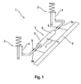
- Fig. 1 schematically shows a front axle 1 of a motor vehicle not shown in detail with McPherson struts 2, which are coupled to each other via a stabilizer 3.
- the stabilizer 3 has two stabilizer halves 3a and 3b, which are each connected via coupling links 4 with the struts 2. Between the stabilizer halves 3a and 3b, a pivot motor 5 is arranged.
- An outer housing 6 of the swivel motor 5 is connected via a further coupling member 7 with a cross member 8 of the chassis or another body-mounted component.
- the stabilizer halves 3a, 3b are pivotally supported in bearings 9, wherein the bearings 9 are also held on the cross member 8 or another body or chassis fixed component.
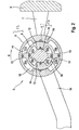
- Fig. 2 shows the pivot motor 5 in the main section.
- an inner housing 9 is rotatably mounted in the outer housing 6, an inner housing 9 is rotatably mounted.
- the inner housing 9 in turn receives a rotor 10.
- the inner housing 9 is rotatably connected to the first stabilizer half 3a, the rotor 10 with the second stabilizer half 3b.
- the rotor 10 is provided with wings 11 on its outside.
- the inner housing 9 has wings 12 on its inner side and wings 13 on its outer side.
- the outer housing 6 has wings 14 on its inner side.
- An annular space 15 formed between the outer housing 6 and the inner housing 9 is divided by the wings 13, 14 into chambers 16a, 16b, 17a, 17b.
- Opposite chambers 16a, 16b and 17a, 17b are connected to each other and are acted upon together with hydraulic fluid.
- a pressurization of the chambers 16 leads, for example, to a pivoting of the inner housing 9 in the direction of arrow R. Since the outer housing 6 is held fixed to the body via the coupling member 7, this simultaneously means pivoting of the inner housing 9 relative to the body, here the cross member 8, in Arrow direction R.
- annular space 18 is formed between the inner housing 9 and the rotor 10, which is divided by the wings 11, 12 in chambers 19 a, 19 b, 20 a, 20 b.
- the rotor 10 is pivoted relative to the inner housing 9 in the direction of arrow R.
- the pressure medium supply lines to the chambers 16, 17, 19 and 20 are not shown in detail and take place in a known manner via hose lines.
- the action of the swing motor 5 is as follows:
- the inner housing 9 and the rotor 10 form a known first pivot motor 21, which controls the movement of the two stabilizer halves 3a, 3b to each other.
- the stabilizer 3 can pivot freely relative to the body 8 of the vehicle, wherein the rotational angular position of the stabilizer halves 3a, 3b to each other by the position of the first pivot motor 21 is determined.
- a second pivot motor 22 is formed by the outer housing 6 and the inner housing 9, wherein the inner housing 9 acts as a rotor to the outer housing 6.
- the first pivot motor 21 can be fixed or pivoted relative to the body 8.
- the second pivot motor 22 acts only on the first stabilizer half 3a directly because it is rotatably connected to the inner housing 9. By applying pressure to the second swivel motor 22, therefore, the wheel contact force on the spring strut 2 connected to the first stabilizer half 3a can be directly influenced; the size of the influence results from the torsional stiffness of the first stabilizer half 3a and the pivot angle of the stabilizer half 3a with respect to a neutral, force-free position.
- the two swivel motors 21, 22 are preferably actuated in such a way that the first swivel motor 21 is controlled in the sense of sway compensation and the second swivel motor 22 in the sense of pitch compensation. Both compensation functions can be controlled separately from each other by the two pivot motors 21,22 in an advantageous manner.
Landscapes
- Engineering & Computer Science (AREA)
- Mechanical Engineering (AREA)
- Vehicle Body Suspensions (AREA)
- Bending Of Plates, Rods, And Pipes (AREA)
Description
- Die Erfindung betrifft einen Schwenkmotor für Stabilisatoren in Kraftfahrzeugen und ein Verfahren zur Ansteuerung des Schwenkmotors.
- Beispielsweise aus der gattungsgemäßen
DE 43 37 815 C1 ist ein Schwenkmotor für Stabilisatoren in Kraftfahrzeugen bekannt, der zwischen zwei Stabilisatorhälften angeordnet ist und die Stabilisatorhälften gegeneinander verschwenken kann. Dadurch ist es möglich, Wankbewegungen des Fahrzeuges auszugleichen. Der Stabilisator besteht aus einem Gehäuse, in dem ein Rotor schwenkbar gehalten ist. Zwischen Flügeln des Rotors und Flügeln des Gehäuses sind Kammern gebildet, die bei Druckbeaufschlagung zu eine Verschwenken des Rotors gegenüber dem Gehäuse führen. Das Gehäuse ist dabei mit der ersten Stabilisatorhälfte und der Rotor mit der zweiten Stabilisatorhälfte verbunden. - Ausgehend von diesem Stand der Technik ist es Aufgabe der Erfindung, einen Schwenkmotor für einen Stabilisator zu schaffen, der auch einen Nickausgleich erlaubt.
- Erfindungsgemäß wird diese Aufgabe mit den Merkmalen des Patentanspruches 1 gelöst. Es wird vorgeschlagen, eine Vorrichtung zum Verschwenken des Gehäuses des Schwenkmotors gegenüber der Karosserie vorzusehen. Durch die zusätzlich geschaffene Bewegungsmöglichkeit können die Stabilisatorhälften nun auch einzeln oder gemeinsam gegenüber der Karosserie um die Stabilisatorachse verschwenkt werden, so dass an jedem Rad des Fahrzeuges zusätzliche Kräfte auf- oder abgebaut werden können. Auf diese Weise ist neben dem Wankausgleich auch ein Nickausgleich möglich. Bevorzugt erfolgt eine Ansteuerung in der Weise, dass der Schwenkmotor im Sinne eines Wankausgleiches und die Vorrichtung zum Verschwenken des Gehäuses des Schwenkmotors im Sinne eines Nickausgleich angesteuert wird.
- Vorteilhafte Weiterbildungen der Erfindung sind in den Unteransprüchen beschrieben.
- So wird vorgeschlagen, zum Verschwenken des Schwenkmotors gegenüber der Karosserie einen zweiten Schwenkmotor zu verwenden, der am Gehäuse des ersten Schwenkmotors angreift. Vorteilhafter Weise ist dabei das Gehäuse des ersten Schwenkmotors Bestandteil des zweiten Schwenkmotors, so dass die Zahl der notwendigen Bauteile reduziert ist. Insbesondere kann das Gehäuse des ersten Schwenkmotors als Rotor des zweiten Schwenkmotors verwendet sein.
- Wenn ein zweiter Schwenkmotor vorgesehen ist, so kann dessen Gehäuse in vorteilhafter Weise Bestandteil eines Achs-Querträgers sein. Durch diesen Aufbau werden Baugewicht und Bauraum gespart; gleichzeitig kann ein ansonsten notwendiges Koppelglied zwischen dem Gehäuse des zweiten Schwenkmotors und der Karosserie eingespart werden.
- Die Erfindung ist nachstehend anhand des in den Fig. dargestellten Ausführungsbeispieles näher erläutert.
- Es zeigen:
- Fig. 1
- Die Anordnung eines erfindungsgemäßen Schwenkmotors in einem Fahrzeug eines Kraftfahrzeuges und
- Fig. 2
- einen Hauptschnitt durch den erfindungsgemäßen Schwenkmotor.
-
Fig. 1 zeigt schematisch eine Vorderachse 1 eines nicht näher gezeigten Kraftfahrzeuges mit McPherson Federbeinen 2, die über einen Stabilisator 3 miteinander gekoppelt sind. Der Stabilisator 3 weist zwei Stabilisatorhälften 3a und 3b auf, die jeweils über Koppelglieder 4 mit den Federbeinen 2 verbunden sind. Zwischen den Stabilisatorhälften 3a und 3b ist ein Schwenkmotor 5 angeordnet. Ein äußeres Gehäuse 6 des Schwenkmotors 5 ist über ein weiteres Koppelglied 7 mit einem Querträger 8 des Fahrwerks oder einem anderen karosseriefesten Bauteil verbunden. Die Stabilisatorhälften 3a, 3b sind in Lagern 9 schwenkbar gehalten, wobei die Lager 9 ebenfalls am Querträger 8 oder einem anderen karosserie- bzw. fahrwerksfesten Bauteil gehalten sind. -
Fig. 2 zeigt den Schwenkmotor 5 im Hauptschnitt. Im äußeren Gehäuse 6 ist ein inneres Gehäuse 9 drehbar gelagert. Das innere Gehäuse 9 nimmt seinerseits einen Rotor 10 auf. Das innere Gehäuse 9 ist mit der ersten Stabilisatorhälfte 3a, der Rotor 10 mit der zweiten Stabilisatorhälfte 3b drehfest verbunden. Der Rotor 10 ist an seiner Außenseite mit Flügeln 11 versehen. Das innere Gehäuse 9 weist an seiner Innenseite Flügel 12 und an seiner Außenseite Flügel 13 auf. Das äußere Gehäuse 6 weist an seiner Innenseite Flügel 14 auf. - Ein zwischen dem äußeren Gehäuse 6 und dem inneren Gehäuse 9 gebildeter Ringraum 15 ist durch die Flügel 13, 14 in Kammern 16a, 16b, 17a, 17b unterteilt. Jeweils gegenüberliegende Kammern 16a, 16b und 17a, 17b sind miteinander verbunden und werden gemeinsam mit Druckflüssigkeit beaufschlagt. Eine Druckbeaufschlagung der Kammern 16 führt beispielsweise zu einem Verschwenken des inneren Gehäuses 9 in Pfeilrichtung R. Da das äußere Gehäuse 6 über das Koppelglied 7 karosseriefest gehalten ist, bedeutet dies gleichzeitig ein Verschwenken des inneren Gehäuses 9 gegenüber der Karosserie, hier dem Querträger 8, in Pfeilrichtung R.
- In gleicher Weise ist zwischen dem inneren Gehäuse 9 und dem Rotor 10 ein Ringraum 18 gebildet, der durch die Flügel 11, 12 in Kammern 19a, 19b, 20a, 20b unterteilt ist. Durch eine Druckbeaufschlagung der gegenüberliegenden Kammern 19 wird der Rotor 10 gegenüber dem inneren Gehäuse 9 in Pfeilrichtung R verschwenkt.
- Die Druckmittelzuleitungen zu den Kammern 16, 17, 19 und 20 sind nicht näher dargestellt und erfolgen in bekannter Weise über Schlauchleitungen.
- Die Wirkung des Schwenkmotors 5 ist wie folgt: Das innere Gehäuse 9 und der Rotor 10 bilden einen an sich bekannten ersten Schwenkmotor 21, der die Bewegung der beiden Stabilisatorhälften 3a, 3b zueinander kontrolliert. Solange keine der äußeren Kammern 16, 17 mit Druck beaufschlagt ist, kann sich der Stabilisator 3 frei gegenüber der Karosserie 8 des Fahrzeuges verschwenken, wobei die Drehwinkelposition der Stabilisatorhälften 3a, 3b zueinander durch die Position des ersten Schwenkmotors 21 bestimmt ist.
- Ein zweiter Schwenkmotor 22 ist durch das äußeren Gehäuse 6 und das innere Gehäuse 9 gebildet, wobei das innere Gehäuse 9 als Rotor zum äußeren Gehäuse 6 wirkt. Bei Druckbeaufschlagung des zweiten Schwenkmotors 22 ist die Bewegungsmöglichkeit des ersten Schwenkmotors 21 eingeschränkt. Der erste Schwenkmotor 21 kann gegenüber der Karosserie 8 festgelegt oder verschwenkt werden.
- Der zweite Schwenkmotor 22 wirkt dabei nur auf die erste Stabilisatorhälfte 3a direkt, da diese mit dem inneren Gehäuse 9 drehfest verbunden ist. Durch Druckbeaufschlagung des zweiten Schwenkmotors 22 kann also die Radaufstandskraft an dem mit der ersten Stabilisatorhälfte 3a verbundenen Federbein 2 direkt beeinflusst werden; die Größe der Beeinflussung ergibt sich aus der Drehsteifigkeit der ersten Stabilisatorhälfte 3a und dem Schwenkwinkel der Stabilisatorhälfte 3a gegenüber einer neutralen, kraftfreien Position.
- Die Bewegung der zweiten Stabilisatorhälfte 3b gegenüber der Karosserie 8 erfolgt indirekt über beide Schwenkmotoren 21,22. So müssen, um nur die erste Stabilisatorhälfte 3a zu bewegen und die zweite Stabilisatorhälfte 3b in ihrer Position festzuhalten, die beiden Schwenkmotoren 21,22 gegensinnig angesteuert werden.
- Bevorzugt werden die beiden Schwenkmotoren 21,22 aber in der Weise angesteuert, dass der erste Schwenkmotor 21 im Sinne eines Wankausgleiches und der zweite Schwenkmotor 22 im Sinne eines Nickausgleiches angesteuert wird. Beide Ausgleichsfunktionen sind durch die beiden Schwenkmotoren 21,22 in vorteilhafter Weise getrennt voneinander ansteuerbar.
Claims (5)
- Schwenkmotor für einen Stabilisator (3) eines Kraftfahrzeuges, wobei der Stabilisator aus zwei Stabilisatorhälften (3a, 3b) besteht und ein Gehäuse (9) des Schwenkmotors (21) mit der ersten Stabilisatorhälfte (3a) und ein Rotor (10) des Schwenkmotors mit der zweiten Stabilisatorhälfte (3b) verbunden ist, dadurch gekennzeichnet, dass eine Vorrichtung (22) zum Verschwenken des Gehäuses (9) des Schwenkmotors gegenüber der Karosserie (8) vorgesehen ist.
- Schwenkmotor nach Anspruch 1, dadurch gekennzeichnet, dass zum Verschwenken des ersten Schwenkmotors (21) gegenüber der Karosserie (8) ein zweiter Schwenkmotor (22) vorgesehen ist.
- Schwenkmotor nach Anspruch 2, dadurch gekennzeichnet, dass das Gehäuse (9) des ersten Schwenkmotors (21) als Rotor des zweiten Schwenkmotors (22) verwendet ist.
- Schwenkmotor nach Anspruch 2 oder 3, dadurch gekennzeichnet, dass das Gehäuse (6) des zweiten Schwenkmotors (22) Bestandteil eines Achs-Querträgers (8) ist.
- Verfahren zur Ansteuerung eines Schwenkmotors nach Anspruch 1, dadurch gekennzeichnet, dass der erste Schwenkmotor (21) im Sinne eines Wankausgleiches und eine Vorrichtung (22) zum Verschwenken des Gehäuses (9) des ersten Schwenkmotors im Sinne eines Nickausgleich angesteuert wird.
Applications Claiming Priority (2)
| Application Number | Priority Date | Filing Date | Title |
|---|---|---|---|
| DE102004002550 | 2004-01-17 | ||
| DE102004002550A DE102004002550A1 (de) | 2004-01-17 | 2004-01-17 | Doppelter Schwenkmotor und Verfahren zur Ansteuerung |
Publications (3)
| Publication Number | Publication Date |
|---|---|
| EP1580046A2 EP1580046A2 (de) | 2005-09-28 |
| EP1580046A3 EP1580046A3 (de) | 2005-10-12 |
| EP1580046B1 true EP1580046B1 (de) | 2008-03-19 |
Family
ID=34716639
Family Applications (1)
| Application Number | Title | Priority Date | Filing Date |
|---|---|---|---|
| EP04025256A Expired - Lifetime EP1580046B1 (de) | 2004-01-17 | 2004-10-23 | Doppelter Schwenkmotor und Verfahren zur Ansteuerung |
Country Status (3)
| Country | Link |
|---|---|
| EP (1) | EP1580046B1 (de) |
| AT (1) | ATE389554T1 (de) |
| DE (2) | DE102004002550A1 (de) |
Families Citing this family (14)
| Publication number | Priority date | Publication date | Assignee | Title |
|---|---|---|---|---|
| DE102005031414B4 (de) * | 2005-07-04 | 2016-01-21 | Bayerische Motoren Werke Aktiengesellschaft | Schwenkmotor |
| DE102005047278A1 (de) * | 2005-10-01 | 2007-04-05 | Bayerische Motoren Werke Ag | Schwenkmotor-Anordnung in einem geteilten Stabilisator eines Fahrzeugs |
| DE102006009524A1 (de) * | 2006-02-28 | 2007-09-06 | Pnp Automotive Gmbh | Stabilisator für ein Kraftfahrzeug |
| US8148055B2 (en) | 2006-06-30 | 2012-04-03 | Infineon Technologies Ag | Method for developing a photoresist |
| DE102007007214A1 (de) | 2007-02-14 | 2008-08-21 | Volkswagen Ag | Anordnung eines Stabilisators an einer Radaufhängung für Kraftfahrzeuge |
| DE102007022179A1 (de) * | 2007-05-11 | 2008-11-13 | Bayerische Motoren Werke Aktiengesellschaft | Schwenkmotor, insbesondere für einen geteilten Querstabilisator eines Fahrzeugs |
| EP2065231A1 (de) * | 2007-11-30 | 2009-06-03 | Nederlandse Organisatie voor Toegepast-Natuuurwetenschappelijk Onderzoek TNO | Aktive Rollenstabilisierungsanordnung, die von einem Servolenkpumpmittel beliefert wird, ein aktiver Strömungstrenner, ein aktiver Strömungsregulator und ein Fahrzeug mit einer solchen aktiven Rollenstabilisierungsanordnung |
| DE102009005895A1 (de) | 2009-01-23 | 2010-07-29 | Audi Ag | Anordnung eines Stabilisators an einer Radaufhängung für Kraftfahrzeuge |
| DE102009005899A1 (de) | 2009-01-23 | 2010-07-29 | Audi Ag | Anordnung eines Stabilisators an einer Radaufhängung für Kraftfahrzeuge |
| DE102009005898A1 (de) | 2009-01-23 | 2010-07-29 | Audi Ag | Anordnung eines Stabilisators an einer Radaufhängung für Kraftfahrzeuge |
| DE102010041404A1 (de) * | 2010-09-27 | 2012-03-29 | Zf Friedrichshafen Ag | Aktiver Torsionswankstabilisator |
| DE102012011919A1 (de) | 2012-06-15 | 2013-12-19 | Audi Ag | Verstellbare Radaufhängung für die Räder einer Achse eines Kraftfahrzeugs |
| DE102012011918A1 (de) | 2012-06-15 | 2013-12-19 | Audi Ag | Verstellbare Radaufhängung für die Räder einer Achse eines Kraftfahrzeugs |
| DE102013002713B4 (de) | 2013-02-16 | 2014-08-28 | Audi Ag | Drehstabfederanordnung für eine Radaufhängung eines Kraftfahrzeugs |
Family Cites Families (14)
| Publication number | Priority date | Publication date | Assignee | Title |
|---|---|---|---|---|
| US2106886A (en) * | 1936-02-12 | 1938-02-01 | Houde Eng Corp | Stabilizer structure for automobiles |
| US2208969A (en) * | 1938-07-30 | 1940-07-23 | Nevin S Focht | Stabilizing means for vehicle bodies |
| DE1105290B (de) * | 1959-10-31 | 1961-04-20 | Daimler Benz Ag | Vorrichtung zur Kurvenstabilisierung des Wagenkastens bei Kraftfahrzeugen, insbesondere solchen mit Luftfederung |
| NL267764A (de) * | 1960-08-03 | |||
| DE1755837A1 (de) * | 1968-06-28 | 1971-12-30 | Daimler Benz Ag | Abfederung von Kraftfahrzeugen mit Stabilisator |
| DE2019372A1 (de) * | 1970-04-22 | 1971-11-04 | Messerschmitt Boelkow Blohm | Druckmittelbetaetigter Stellmotor |
| JPS5143521A (en) * | 1974-10-14 | 1976-04-14 | Nissan Motor | Jidoshano kagensokujishataishiseiseigyosochi |
| JP3092090B2 (ja) * | 1991-10-03 | 2000-09-25 | カヤバ工業株式会社 | スタビライザ制御装置 |
| DE29521157U1 (de) * | 1995-09-12 | 1996-09-05 | Fichtel & Sachs Ag, 97424 Schweinfurt | Fahrzeugachse mit verstellbarem Stabilisator |
| DE19754539C2 (de) * | 1997-12-09 | 2001-11-29 | Mannesmann Sachs Ag | Schwenkmotor |
| DE19802489A1 (de) * | 1998-01-23 | 1999-03-11 | Daimler Benz Ag | Mehrachsiger, motorgetriebener Kraftwagen, insbesondere Personenkraftwagen |
| DE19930444C5 (de) * | 1999-07-02 | 2005-10-20 | Daimler Chrysler Ag | Stabilisatoranordnung für ein Kraftfahrzeug |
| NL1019456C2 (nl) * | 2001-11-30 | 2003-06-03 | Skf Ab | Stabilisatorsysteem voor een voertuig. |
| DE10242552B4 (de) * | 2002-09-13 | 2004-09-16 | Audi Ag | Vorrichtung zum elektromechanischen Verstellen |
-
2004
- 2004-01-17 DE DE102004002550A patent/DE102004002550A1/de not_active Withdrawn
- 2004-10-23 AT AT04025256T patent/ATE389554T1/de not_active IP Right Cessation
- 2004-10-23 DE DE502004006569T patent/DE502004006569D1/de not_active Expired - Lifetime
- 2004-10-23 EP EP04025256A patent/EP1580046B1/de not_active Expired - Lifetime
Also Published As
| Publication number | Publication date |
|---|---|
| DE502004006569D1 (de) | 2008-04-30 |
| DE102004002550A1 (de) | 2005-08-04 |
| ATE389554T1 (de) | 2008-04-15 |
| EP1580046A2 (de) | 2005-09-28 |
| EP1580046A3 (de) | 2005-10-12 |
Similar Documents
| Publication | Publication Date | Title |
|---|---|---|
| EP1580046B1 (de) | Doppelter Schwenkmotor und Verfahren zur Ansteuerung | |
| EP2956315B1 (de) | Radaufhängung für ein kraftfahrzeug | |
| DE102014011193B4 (de) | Vorrichtung zum Verstellen von Sturz und/oder Spur eines Fahrzeugrads mit einer Bremsmomentabstützung | |
| DE102013216029B4 (de) | Lenkbare Vorderachse für Räder eines zweispurigen Kraftfahrzeugs und zweispuriges Kraftfahrzeug mit einer solchen Vorderachse | |
| DE102012108552B4 (de) | Aktives wankstabilisierungssystem | |
| DE102009033105B4 (de) | Verstellvorrichtung für Radaufhängungen von Kraftfahrzeugen | |
| DE102014201876A1 (de) | Vorrichtung zum Einstellen der Spur und/oder des Sturzes für ein Fahrwerk eines Kraftfahrzeugs | |
| DE3809995A1 (de) | Hintere aufhaengungseinrichtung fuer motorfahrzeuge | |
| DE102005037973A1 (de) | Einrichtung zur Verstellung des Radsturzes oder der Vorspur | |
| DE102008048567A1 (de) | Vorrichtung zum Verstellen eines Rades einer Radaufhängung | |
| DE102010061018A1 (de) | Radaufhängung eines Kraftfahrzeugs | |
| EP3172069B1 (de) | Vorrichtung zum verstellen von sturz und/oder spur der räder von kraftfahrzeugen | |
| DE102014011110B4 (de) | Vorrichtung zum Verstellen von Sturz und/oder Spur eines Fahrzeugrads mit Drehmomentübertragungselement | |
| WO2016202513A1 (de) | Gelenkverbindung und anordnung zur aufhängung eines rades | |
| DE10351574A1 (de) | Verfahren zur Veränderung des Eigenlenkverhaltens der Hinterräder eines zweispurigen Kraftfahrzeugs | |
| EP1700721A1 (de) | Vorrichtung zum längenveränderlichen Verstellen eines Lenkers | |
| DE102015202208A1 (de) | Verfahren zum Betrieb einer Hinterradlenkung sowie Hinterradlenkung für ein Fahrzeug | |
| DE102020113947A1 (de) | Radaufhängung für eine Fahrzeug-Hinterachse | |
| DE102008027326A1 (de) | Einrichtung zur Verstellung der Vorspur | |
| DE102014214229A1 (de) | Lenkung für eine Verbundlenkerachse | |
| DE102012221699A1 (de) | Radaufhängung für ein Fahrzeug mit aktiver Radsturzverstellung | |
| DE102020123524B4 (de) | Radmodul für ein Kraftfahrzeug | |
| DE102011088178A1 (de) | Achse eines zweispurigen Fahrzeugs mit einem Längslenker | |
| EP2559605A2 (de) | Schienenfahrzeug mit einstufiger Federung | |
| DE102016222157A1 (de) | Aufgelöste McPherson-Radaufhängung |
Legal Events
| Date | Code | Title | Description |
|---|---|---|---|
| PUAI | Public reference made under article 153(3) epc to a published international application that has entered the european phase |
Free format text: ORIGINAL CODE: 0009012 |
|
| PUAL | Search report despatched |
Free format text: ORIGINAL CODE: 0009013 |
|
| AK | Designated contracting states |
Kind code of ref document: A2 Designated state(s): AT BE BG CH CY CZ DE DK EE ES FI FR GB GR HU IE IT LI LU MC NL PL PT RO SE SI SK TR |
|
| AX | Request for extension of the european patent |
Extension state: AL HR LT LV MK |
|
| AK | Designated contracting states |
Kind code of ref document: A3 Designated state(s): AT BE BG CH CY CZ DE DK EE ES FI FR GB GR HU IE IT LI LU MC NL PL PT RO SE SI SK TR |
|
| AX | Request for extension of the european patent |
Extension state: AL HR LT LV MK |
|
| 17P | Request for examination filed |
Effective date: 20060412 |
|
| AKX | Designation fees paid |
Designated state(s): AT DE FR GB IT SE |
|
| GRAP | Despatch of communication of intention to grant a patent |
Free format text: ORIGINAL CODE: EPIDOSNIGR1 |
|
| GRAS | Grant fee paid |
Free format text: ORIGINAL CODE: EPIDOSNIGR3 |
|
| GRAA | (expected) grant |
Free format text: ORIGINAL CODE: 0009210 |
|
| AK | Designated contracting states |
Kind code of ref document: B1 Designated state(s): AT DE FR GB IT SE |
|
| REG | Reference to a national code |
Ref country code: GB Ref legal event code: FG4D Free format text: NOT ENGLISH |
|
| REF | Corresponds to: |
Ref document number: 502004006569 Country of ref document: DE Date of ref document: 20080430 Kind code of ref document: P |
|
| RAP2 | Party data changed (patent owner data changed or rights of a patent transferred) |
Owner name: DR. ING. H.C. F. PORSCHE AKTIENGESELLSCHAFT |
|
| RAP2 | Party data changed (patent owner data changed or rights of a patent transferred) |
Owner name: DR. ING. H.C. F. PORSCHE AKTIENGESELLSCHAFT |
|
| PG25 | Lapsed in a contracting state [announced via postgrant information from national office to epo] |
Ref country code: SE Free format text: LAPSE BECAUSE OF FAILURE TO SUBMIT A TRANSLATION OF THE DESCRIPTION OR TO PAY THE FEE WITHIN THE PRESCRIBED TIME-LIMIT Effective date: 20080619 |
|
| ET | Fr: translation filed | ||
| PLBE | No opposition filed within time limit |
Free format text: ORIGINAL CODE: 0009261 |
|
| STAA | Information on the status of an ep patent application or granted ep patent |
Free format text: STATUS: NO OPPOSITION FILED WITHIN TIME LIMIT |
|
| 26N | No opposition filed |
Effective date: 20081222 |
|
| REG | Reference to a national code |
Ref country code: FR Ref legal event code: TP |
|
| REG | Reference to a national code |
Ref country code: FR Ref legal event code: CD |
|
| PG25 | Lapsed in a contracting state [announced via postgrant information from national office to epo] |
Ref country code: AT Free format text: LAPSE BECAUSE OF NON-PAYMENT OF DUE FEES Effective date: 20081023 |
|
| PGFP | Annual fee paid to national office [announced via postgrant information from national office to epo] |
Ref country code: GB Payment date: 20091022 Year of fee payment: 6 Ref country code: IT Payment date: 20091024 Year of fee payment: 6 |
|
| PGFP | Annual fee paid to national office [announced via postgrant information from national office to epo] |
Ref country code: FR Payment date: 20101104 Year of fee payment: 7 |
|
| REG | Reference to a national code |
Ref country code: FR Ref legal event code: TP |
|
| REG | Reference to a national code |
Ref country code: GB Ref legal event code: 732E Free format text: REGISTERED BETWEEN 20110310 AND 20110316 |
|
| REG | Reference to a national code |
Ref country code: GB Ref legal event code: 732E Free format text: REGISTERED BETWEEN 20110331 AND 20110406 |
|
| GBPC | Gb: european patent ceased through non-payment of renewal fee |
Effective date: 20101023 |
|
| PG25 | Lapsed in a contracting state [announced via postgrant information from national office to epo] |
Ref country code: GB Free format text: LAPSE BECAUSE OF NON-PAYMENT OF DUE FEES Effective date: 20101023 |
|
| PG25 | Lapsed in a contracting state [announced via postgrant information from national office to epo] |
Ref country code: IT Free format text: LAPSE BECAUSE OF NON-PAYMENT OF DUE FEES Effective date: 20101023 |
|
| REG | Reference to a national code |
Ref country code: FR Ref legal event code: ST Effective date: 20120629 |
|
| PG25 | Lapsed in a contracting state [announced via postgrant information from national office to epo] |
Ref country code: FR Free format text: LAPSE BECAUSE OF NON-PAYMENT OF DUE FEES Effective date: 20111102 |
|
| PGFP | Annual fee paid to national office [announced via postgrant information from national office to epo] |
Ref country code: DE Payment date: 20151015 Year of fee payment: 12 |
|
| REG | Reference to a national code |
Ref country code: DE Ref legal event code: R119 Ref document number: 502004006569 Country of ref document: DE |
|
| PG25 | Lapsed in a contracting state [announced via postgrant information from national office to epo] |
Ref country code: DE Free format text: LAPSE BECAUSE OF NON-PAYMENT OF DUE FEES Effective date: 20170503 |