EP1579596B1 - Ünterträgern-sendeleistungsregelung - Google Patents
Ünterträgern-sendeleistungsregelung Download PDFInfo
- Publication number
- EP1579596B1 EP1579596B1 EP03814984.5A EP03814984A EP1579596B1 EP 1579596 B1 EP1579596 B1 EP 1579596B1 EP 03814984 A EP03814984 A EP 03814984A EP 1579596 B1 EP1579596 B1 EP 1579596B1
- Authority
- EP
- European Patent Office
- Prior art keywords
- subcarrier
- channel
- subcarriers
- itpc
- circuitry
- Prior art date
- Legal status (The legal status is an assumption and is not a legal conclusion. Google has not performed a legal analysis and makes no representation as to the accuracy of the status listed.)
- Expired - Lifetime
Links
- 230000005540 biological transmission Effects 0.000 title claims description 24
- 239000000969 carrier Substances 0.000 title description 2
- 238000004891 communication Methods 0.000 claims description 27
- 238000000034 method Methods 0.000 claims description 26
- 230000004044 response Effects 0.000 claims description 18
- 238000005562 fading Methods 0.000 claims description 15
- 238000012360 testing method Methods 0.000 claims description 13
- 238000012545 processing Methods 0.000 claims description 4
- 238000001514 detection method Methods 0.000 description 23
- 238000001228 spectrum Methods 0.000 description 15
- 230000006870 function Effects 0.000 description 13
- 238000004088 simulation Methods 0.000 description 13
- 238000012546 transfer Methods 0.000 description 13
- 238000010586 diagram Methods 0.000 description 8
- 230000000694 effects Effects 0.000 description 6
- 238000013507 mapping Methods 0.000 description 5
- 230000008569 process Effects 0.000 description 5
- 238000004364 calculation method Methods 0.000 description 4
- 238000012549 training Methods 0.000 description 4
- 230000003044 adaptive effect Effects 0.000 description 3
- 238000011144 upstream manufacturing Methods 0.000 description 3
- 230000002411 adverse Effects 0.000 description 2
- 239000000872 buffer Substances 0.000 description 2
- 230000001934 delay Effects 0.000 description 2
- 230000003111 delayed effect Effects 0.000 description 2
- 238000013461 design Methods 0.000 description 2
- 238000012986 modification Methods 0.000 description 2
- 230000004048 modification Effects 0.000 description 2
- 238000005316 response function Methods 0.000 description 2
- 230000003068 static effect Effects 0.000 description 2
- 230000001419 dependent effect Effects 0.000 description 1
- 238000000605 extraction Methods 0.000 description 1
- 238000001914 filtration Methods 0.000 description 1
- 230000006872 improvement Effects 0.000 description 1
- 238000011835 investigation Methods 0.000 description 1
- 238000006467 substitution reaction Methods 0.000 description 1
Images


Classifications
-
- H—ELECTRICITY
- H04—ELECTRIC COMMUNICATION TECHNIQUE
- H04W—WIRELESS COMMUNICATION NETWORKS
- H04W52/00—Power management, e.g. Transmission Power Control [TPC] or power classes
- H04W52/04—Transmission power control [TPC]
- H04W52/38—TPC being performed in particular situations
- H04W52/42—TPC being performed in particular situations in systems with time, space, frequency or polarisation diversity
-
- H—ELECTRICITY
- H04—ELECTRIC COMMUNICATION TECHNIQUE
- H04L—TRANSMISSION OF DIGITAL INFORMATION, e.g. TELEGRAPHIC COMMUNICATION
- H04L27/00—Modulated-carrier systems
- H04L27/26—Systems using multi-frequency codes
- H04L27/2601—Multicarrier modulation systems
-
- H—ELECTRICITY
- H04—ELECTRIC COMMUNICATION TECHNIQUE
- H04B—TRANSMISSION
- H04B7/00—Radio transmission systems, i.e. using radiation field
- H04B7/02—Diversity systems; Multi-antenna system, i.e. transmission or reception using multiple antennas
- H04B7/04—Diversity systems; Multi-antenna system, i.e. transmission or reception using multiple antennas using two or more spaced independent antennas
- H04B7/06—Diversity systems; Multi-antenna system, i.e. transmission or reception using multiple antennas using two or more spaced independent antennas at the transmitting station
- H04B7/0613—Diversity systems; Multi-antenna system, i.e. transmission or reception using multiple antennas using two or more spaced independent antennas at the transmitting station using simultaneous transmission
- H04B7/0615—Diversity systems; Multi-antenna system, i.e. transmission or reception using multiple antennas using two or more spaced independent antennas at the transmitting station using simultaneous transmission of weighted versions of same signal
-
- H—ELECTRICITY
- H04—ELECTRIC COMMUNICATION TECHNIQUE
- H04W—WIRELESS COMMUNICATION NETWORKS
- H04W52/00—Power management, e.g. Transmission Power Control [TPC] or power classes
- H04W52/04—Transmission power control [TPC]
- H04W52/18—TPC being performed according to specific parameters
- H04W52/24—TPC being performed according to specific parameters using SIR [Signal to Interference Ratio] or other wireless path parameters
Definitions
- BER Bit Error Rate
- PER Packet Error Rate
- US 2002/0027875 A1 discloses an OFDM transmitting and receiving apparatus and OFDM transmitting and receiving method wherein an average value of reception power of a plurality of subcarriers is calculated by a control circuit, and the average value is divided by envelopes of received signals of the plurality of subcarriers, respectively, so as to calculate a coefficient signal of each subcarrier.
- a plurality of multipliers multiply transmitting signals of the plurality of subcarriers output from a plurality of mapping circuits by the coefficient signals, respectively, wherein, power between the subcarriers at a reception time can be maintained substantially constant so as to improve an error rate characteristic.
- EP-A-1 037 303 discloses an apparatus and method for generating transmitter antenna weights, particularly in multicarrier systems such as OFDM systems, wherein antenna weights for a transmit path between two communication devices, the first device having an antenna array are generated in the second device and fed back to weighting circuitry in the first device. Specifically a parameter of a sub-carrier is measured and, based on the respective parameter of each sub-carrier, a weighting is applied thereto i.e. in all cases. Sub-bands individually meeting certain criteria are identified and corrected.
- Embodiments of one aspect of the present invention provide a device and/or a method to enable a communication station to operate at optimal, near optimal, or minimal overall BER and/or PER.
- Embodiments of another aspect of the present invention provide a device and/or a method to detect usage of a BER and/or PER optimizing/minimizing solution.
- Embodiments of the present invention introduce a novel adaptive Intelligent Transmitted Power Control (ITPC) scheme.
- ITPC Intelligent Transmitted Power Control
- the scope of the present invention is not limited in this regard, the ITPC scheme may be used in conjunction with various types of wireless communication systems, for example, systems operating in accordance with predefined standards, for example IEEE standard 802.11a, or other OFDM or DMT systems, including, but not limited to, systems that use multiple carriers and/or subcarriers simultaneously.
- station 100 may initially estimate channel quality and subcarrier power gains, using a signal received from station 110. Based on these estimations, station 100 may perform optimal or near-optimal power allocation through subcarriers for transmission. In an embodiment of the present invention, the power allocation or reallocation may be performed, for example, with a constraint that the total transmission power remains substantially constant.
- the term allocation, as defined herein, may also refer to reallocation of power. Reallocation of power in accordance with embodiments of the invention may adjust an initial power allocation, or to adjust a previous power reallocation, of the transmissions of stations 100 and 110.
- station 100 may use the same type of modulation and coding technique in substantially all data subcarriers.
- more power may be allocated to subcarriers with lower channel power gain ("bad" subcarriers) than to subcarriers with higher channel power gain (“good” subcarriers).
- SNR Signal-to-Noise Ratio
- This power allocation scheme may be optimal or near-optimal in terms of overall BER/PER minimization or, conversely, total average throughput maximization.
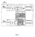
- FIG. 2 schematically illustrates a functional block diagram of an OFDM standard 802.11 a transceiver with an ITPC scheme 250 according to exemplary embodiments of the invention.
- ITPC scheme 250 may operate between a transmitter (TX) part 200 and a receiver (RX) part 210 of station 100, which may include any components of a transceiver, as are known in the art, in addition to the components specifically described herein.
- the ITPC scheme 250 may include a local subcarrier SNR Pre-Equalizer 220, and a Subcarrier Weighting Unit 230, either or both of which may be implemented using any combination of hardware and/or software as may be desired.
- RX part 210 may receive a packet from another station, e.g., station 110. Then, SNR Pre-Equalizer 220 may switch the ITPC scheme 250 "on” or "off", and may calculate weights for the TX part 200 using any suitable weight calculation method known in the art.
- Subcarrier Weighting Unit 230 may generate output signals, which may be based on multiplying subcarrier weights calculated in SNR Pre-Equalizer 220 by corresponding subcarrier complex numbers, which may represent constellation points from a mapping block. As illustrated in FIG.
- the system may include and use other components as are known in the art; for example, RX part a Serial-to-Parallel (S/P) converter and Remove Guards Intervals (RGI) unit 270, a Fast Fourier Transform (FFT) 274, a Channel Estimation & Equalization unit 276, and a Demapping unit 278, and TX part 200 may include an Inverse FFT (IFFT) 280, and a Parallel-to-Serial (P/S) converter and Add Guards Intervals (AGI) unit 282, all of which units may include hardware and/or software components as are known in the art. Additionally, the system may include and use an internal and/or external Antenna 290.
- S/P Serial-to-Parallel
- RKI Remove Guards Intervals
- FFT Fast Fourier Transform
- AGI Add Guards Intervals
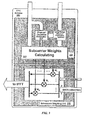
- FIG. 3 schematically illustrates in more detail a functional block diagram of the ITPC scheme 250 and its units, e.g., the SNR Pre-Equalizer 220 and the Subcarrier Weighting Unit 230.
- SNR Pre-Equalizer 220 may include a Channel Deviation Estimator 310, a Subcarrier Weights Calculating Sub-unit 320 and, optionally, a Long-Range Channel Prediction Sub-unit 330.
- the channel deviation value may be compared with a given threshold, which may determine channel quality.
- the threshold value may be pre-determined in accordance with theoretical calculations and/or simulations.
- the threshold value may be pre-stored in an optional memory device or buffer (not shown), or may be built-in or hard-coded into the method being used for power allocation in accordance with the present invention.
- the scope of the present invention is not limited in this regard, it is noted that theoretical calculations and simulations have shown that the ITPC scheme in accordance with some embodiments of the present invention may improve performance for channel deviation of up to 6dB. It is further noted that embodiments of the present invention may use this particular or other threshold values, and that, for example, with a non-benign channel which has a relatively high channel deviation, other schemes of adaptive bit and power allocation may be used.
- the Subcarrier Weights Calculating Sub-unit 320 may define subcarrier weights such that higher weights are assigned to subcarriers with smaller channel gains, and smaller weights are assigned to subcarriers with larger channel gains.
- the Subcarrier Weights Calculating Sub-unit 320 may use inverse subcarriers fading gains estimates (ISFGE) from a standard OFDM channel equalization unit.
- the Subcarrier Weights Calculating Sub-unit 320 may use subcarriers fading gains estimates (SFGE) from a standard OFDM channel equalization unit. It is noted that in order to satisfy total transmitter power requirements, the sum of the squares of the subcarrier weight magnitudes may be constant and equal to the number of subcarriers.
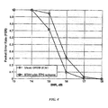
- FIG. 4 and FIG. 5 present simulation results for OFDM transceivers with a data rate of 36 Megabits/second, a 16-QAM modulation type, a coding rate of 3/4, and a packet length of 1,000 bytes.
- An aspect of some embodiments of the present invention introduces an ITPC Detector that may detect a station using an ITPC scheme, for example, a licensed and/or a non-licensed ITPC scheme according to embodiments of the present invention, as described above. Additionally, the ITPC Detector may detect other adaptive power loading schemes, such as, for example, schemes that may vary modulation type, coding type and/or power allocation per subcarrier simultaneously.
- the ITPC Detector may be realized in a Physical Layer (PHY) of an OFDM transceiver and may be controlled from a Medium Access Control (MAC) layer.
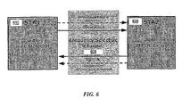
- the ITPC Detector may be a part of a first transceiver (e.g., station STA1 in FIG. 6 ), which may establish a connection with a second transceiver (e.g., station STA2 in FIG. 6 ) that may have an ITPC scheme such as, for example, the ITPC schemes described above.
- FIG. 6 schematically illustrates a communication system with an ITPC Detector in accordance with exemplary embodiments of the present invention.
- the system includes at least two stations, namely, station 610 (STA1) and station 620 (STA2), respectively, operating over a frequency-selective channel 600.
- STA1 610 may include an ITPC Detector
- STA2 620 may include an ITPC scheme.
- the aforethought distortion may be estimated together with the channel transfer function using, for example, a standard channel estimation unit (276 in FIG. 2 ), because station 620 may not separate channel distortion and aforethought distortion.
- a SNR Pre-Equalizer in station 620 may recalculate channel estimates from a standard channel estimation unit (276 in FIG. 2 ), to provide subcarrier weights for a Subcarrier Weighting Unit (230 in FIG. 2 ) of station 620, in analogy to the description above with reference to FIG. 3 .
- These estimations may be performed taking into account a total transfer function, which may be equal to the product of the aforethought distortion transfer function and a physical channel transfer function in the frequency domain.
- the total response function may be equal to the convolution of two response functions, for example, a response of the aforethought distortion and a response of the physical channel.
- STA2 station under investigation
- STA2 may operate as if a usual OFDM signal has passed through a specific channel, and therefore STA2 may attempt to pre-equalize the channel. This may result in a transmitted signal containing inverse aforethought pre-distortion, which may enable the ITPC Detector to detect activity of an ITPC scheme.
- the RX part of station 610 may receive its own inverted aforethought distortion instead of a perfectly equalized frequency-flat channel response. As explained above, station 610 may detect this response to its own aforethought distortion using matched filtering, which may be performed by the ITPC Detector of station 610.
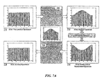
- FIG. 7A schematically illustrates an example of using an ITPC scheme by STA2 upon connection with STA1, without a detection process.
- Block 710 depicts a spectrum that may be transmitted by STA1
- block 712 depicts a spectrum that may be received by STA2.
- Block 714 depicts a pre-equalized transmitted spectrum of STA2, and block 716 depicts a spectrum that may be received by STA1.
- STA1 and STA2 may operate over a reciprocal, frequency-selective channel 720, whose transfer function may be, for example, as indicated at block 722.
- FIG. 7B schematically illustrates an exemplary detection of an ITPC scheme activity at STA2, by an ITPC Detector at STA1, in accordance with embodiments of the present invention.
- Block 750 depicts the spectrum transmitted by STA1 with aforethought distortion
- block 752 depicts the spectrum received STA2.
- Block 754 depicts a pre-equalized transmitted spectrum of STA2
- block 756 depicts the spectrum that may be received by STA1, which spectrum may contain inverted aforethought distortion.
- STA1 and STA2 may operate over a reciprocal, frequency-selective channel 760, whose transfer function may be, for example, as indicated at block 762.
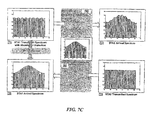
- FIG. 7C schematically illustrates an example of non-detection of ITPC scheme activity for a STA2 having a conventional OFDM transceiver.
- Block 770 depicts a spectrum with aforethought distortion that may be transmitted by station 610, while block 772 depicts the spectrum that may be received by station 620.
- Block 774 depicts the spectrum that may be transmitted by station 620, and block 776 depicts the spectrum received by station 610.
- STA1 and STA2 may operate over a reciprocal frequency-selective channel 780, whose transfer function is indicated at block 782.
- An ITPC Detector which may be used in conjunction with OFDM signals, may include three main units: a Test Generator; an Aforethought Distortion Unit; and a Detection Sub-unit. Each one of these units may be implemented in a time domain and/or a frequency domain.
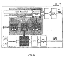
- FIGS. 8A and 8B illustrate two exemplary implementations of ITPC Detector schemes in accordance with embodiments of the invention.
- FIG. 8A schematically illustrates part of a station/transceiver including an ITPC Detector 805 in accordance with one exemplary embodiment of the present invention, including components implemented in the frequency domain.
- the ITPC Detector 805 of FIG. 8A may include a Test Generator 800 to produce a predefined test signal in the frequency domain, wherein complex weights may be close to real units because the expected aforethought distortion in this case may be small.
- These complex weights may be used as input signals for an Aforethought Distortion Unit, which may be implemented, for example, in the form of a Subcarriers Weighting Unit 810, wherein subcarrier complex numbers from a modulation mapping block may be multiplied by corresponding weights, which may be provided by test signals produced by Test Generator 800. It is noted that to satisfy total transmitter power requirements, the sum of the squares of the subcarrier weight magnitudes may be constant and equal to the number of subcarriers, if desired.
- weighted subcarrier complex numbers may be transferred to an IFFT unit, as is known in the art, and further processed using any suitable components for processing OFDM TX downstream signals.
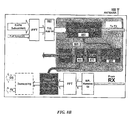
- FIG. 8B schematically illustrates another exemplary embodiment of a station/transceiver including an ITPC Detector 855 in accordance with embodiments of the present invention
- FIG. 9 schematically illustrates a functional scheme of a Transversal Filter, which may be included in exemplary implementations of ITPC Detector 855.
- components may be implemented in the time domain, except a Matched Filter 890, which may be implemented in the frequency domain, as described above with reference to the embodiment of FIG. 8A .
- test Generator 850 may produce a predefined test signal in the time domain, including, for example, real and/or complex weights, e.g., with magnitudes of less than one, because the aforethought distortion may be small, as described above.
- complex weights may be used as input signals in an Aforethought Distortion Unit, which may be implemented in the form of a time domain Transversal Filter 860, which may receive a signal from a Parallel-to-Serial Converter and/or a Guards Intervals (GI) adding unit, as indicated at block 862.
- Input signals of the Transversal Filter 860 may represent an entire time domain OFDM input stream.
- Transversal Filter 860 may also be equal to one, in normalized values.
- the Detection Sub-Unit (not shown) in accordance with this exemplary embodiment of the invention may be generally similar to the Detection Sub-unit described above with reference to FIG. 8A ; however, in this exemplary embodiment, Matched Filter coefficients may be recalculated from a time domain signal of Test Generator 850 by an FFT unit 870, which may be used to convert the time domain signal to a frequency domain signal.
- implementation of some embodiments of the invention may use either subcarrier complex fading gain estimates and/or a matched filter with complex coefficients, in order to improve detection efficiency.
- the ITPC Detector may include a storage device, which may allow accumulating Matched Filter responses for several consecutive packets from STA2. The detection efficiency may also be dependent on the precision of channel estimates.
- Matlab(R) simulation results were performed for reciprocal two-ray (with inter-ray delay of 50 nanoseconds and relative power of -15dB), static, frequency-selective channel model.
- the ITPC Detector was implemented in the frequency domain, in accordance with the exemplary embodiment illustrated schematically in FIG. 8A .
- the simulation used two long training symbols, in accordance with standard OFDM 802.11a, for channel transfer function ML estimation.
- the aforethought distortion was -25dB, with a complex exponential form.
- the Matched Filter was implemented in the frequency domain, with coefficients substantially complex-conjugate to the back response of the aforethought distortion.
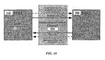
- an aforethought distortion of an OFDM signal may be used for transmission of service information, without adversely affecting the main OFDM data streams, when both stations, e.g., STA1 and STA2, may be used as ITPC transceivers and include ITPC detectors.
- FIG. 10 schematically illustrates an exemplary embodiment of such a transmission system in accordance with embodiments of the present invention.
- Each one of stations 1010 (STA1) and 1020 (STA2) may include an ITPC detector.
- Stations 1010 and 1020 may operate over a frequency-selective channel 1000, and both stations may have a priori information of a set of Test Generator signals, which may be referred to as "codewords".
- a channel response time delay usually does not exceed about 250 nanoseconds, or 5 samples, and therefore nonzero values of Transversal Filter coefficients h n may be preferable for the positions of 6 ⁇ n ⁇ 10, if desired, although the scope of the invention is not limited in this respect.
- a Transversal Filter may produce delayed copies of an original signal. Values of coefficients of the Transversal Filter may correspond to magnitudes of such copies, and the number of particular coefficient may determine the delay of a corresponding copy.
- the channel may also produce copies of the signal due to multi-path propagation (e.g., channel response).
- the delays corresponding to positions of Transversal Filter nonzero coefficients are less then the channel response time (e.g., n ⁇ 5), there may be interference between responses from the Transversal Filter and the channel responses, that may affect the detection and/or transmission of service information performance.
- Transversal Filter responses delays are larger than the difference between OFDM Guard Interval and channel response time (e.g., n>10), then the Transversal Filter responses delayed by the channel may cause unwanted inter-symbol interference because the total delay may exceed the OFDM Guard Interval value.
- the magnitudes of the coefficients described above may be relatively small, for example, in the range of about -20dB to -25dB, in order to have only a negligible impact on the OFDM system power allocation and the BER/PER performance characteristics.
- An ITPC Detector scheme with such a special Test Generator may be referred to as "ITPC Transceiver".
- Any of the stations may transmit service information using its Aforethought Distortion Unit, and/or may receive service information from another station using its Detection Unit.
- service information may be extracted by using a standard channel estimation unit and one or two long training symbols processing.
- the performance characteristics of such transmission for a set of simple codewords e.g., with one nonzero transversal filter coefficient, h n , may be similar to the characteristics of an ITPC Detector as described above.
- optimizing the selection of a set of codewords using a suitable scheme or in accordance with suitable criteria, may substantially improve the service information throughput.
- a dedicated high precision channel estimation unit may be used by an ITPC Detector, or included in the ITPC Detector.
- This dedicated high precision channel estimation unit may process an entire OFDM data packet, in order to improve performance of transmission of service information.
- Yet another method for improvement of service information throughput over a standard OFDM signal stream includes using an ITPC scheme simultaneously with an ITPC transceiver, wherein the ITPC scheme may equalize the physical channel transfer function, and the transceiver may transmit more service information through a pre-equalized channel.
- Embodiments of the present invention may be implemented by software, by hardware, or by any combination of software and/or hardware as may be appropriate for specific applications or in accordance with specific design requirements.
- the system of the invention may further include memory units, buffers and/or registers for temporary and/or permanent storage of data, as well. as general, multi-purpose and/or specific processors, circuits, logic systems, operators, circuitry, blocks, units and/or sub-units that may perform any operation, or any combination of operations, described above.
- Such units, or any combination thereof may be noted herein as “circuitry", and may be external and/or internal to a communication device, in whole or in part.
Landscapes
- Engineering & Computer Science (AREA)
- Computer Networks & Wireless Communication (AREA)
- Signal Processing (AREA)
- Mobile Radio Communication Systems (AREA)
Claims (15)
- Verfahren zur Zuweisung von Sendeleistung für eine drahtlose Kommunikationsstation unter Verwendung einer Mehrzahl von Zwischenträgern, umfassend:Empfangen eines Signals, das über Zwischenträger gesendet wird;Schätzen von Schwundverstärkungen der Mehrzahl von Zwischenträgern aus dem empfangenen Signal;Bestimmen einer Kanalabweichung für die Zwischenträger (310);gekennzeichnet durchdie Kanalabweichung, die das Verhältnis zwischen der Zwischenträgerverstärkung maximaler Größe und der Zwischenträgerverstärkung minimaler Größe ist;Modifizieren eines Sendesignals durch Zuweisen von Sendeleistung zu einer Kommunikationsstation basierend auf dem Multiplizieren aller Zwischenträgerdaten mit einem entsprechenden Zwischenträgergewicht (230) nur dann, wenn die Kanalabweichung gleich einer oder niedriger als eine vorbestimmte Schwelle ist, wobei die Zwischenträgergewichte basierend auf den Schwundverstärkungen berechnet werden,Modifizieren andernfalls dann, wenn die Kanalabweichung höher als die vorbestimmte Schwelle ist, des Sendesignals durch Zuweisen der Sendeleistung zur Kommunikationsstation basierend auf dem Multiplizieren aller Zwischenträgerdaten mit einem Zwischenträger-Einheitsgewicht; undBereitstellen des Sendesignals zur Übertragung über die Zwischenträger.
- Verfahren nach Anspruch 1, ferner umfassend ein Empfangen von inversen Zwischenträger-Schwundverstärkungen von einer Kanalentzerrungseinheit und Berechnen des Zwischenträgergewichts basierend auf den Schwundverstärkungen.
- Verfahren nach Anspruch 1, wobei das Berechnen des Zwischenträgergewichts ein Verwenden von langfristiger Kanalvorhersage umfasst.
- Verfahren nach Anspruch 1, umfassend:Erkennen der Verwendung eines Leistungszuweisungsschemas basierend auf einer Antwort auf ein Testsignal in einem empfangenen Zwischenträger.
- Verfahren nach Anspruch 4, wobei das Erkennen ein Akkumulieren von Anpassungsfilterantworten für mindestens zwei Datenpakete des empfangenen Zwischenträgers umfasst.
- Verfahren nach Anspruch 4, ferner umfassend ein Extrahieren von Dienstinformationen aus dem empfangenen Zwischenträger.
- Verfahren nach Anspruch 4, ferner umfassend ein Senden von Dienstinformationen im gesendeten Zwischenträger.
- Verfahren nach Anspruch 7, wobei das Senden der Dienstinformationen ein Senden der Dienstinformationen durch einen Kanal umfasst.
- Verfahren nach Anspruch 8, ferner umfassend ein Vorentzerren des Kanals.
- Verfahren nach Anspruch 4, ferner umfassend ein Verarbeiten eines Datenpakets des empfangenen Zwischenträgers.
- Computerimplementiertes Speichermedium mit darauf gespeicherten Anweisungen, die, wenn von einer Verarbeitungsplattform ausgeführt, zu Folgendem führen:Ausführen der Verfahrensschritte nach einem der Ansprüche 1 bis 10.
- Drahtlose Kommunikationsvorrichtung zur Zuweisung von Sendeleistung für eine drahtlose Kommunikationsstation unter Verwendung einer Mehrzahl von Zwischenträgern, umfassend:Schaltungsanordnung zum Empfangen eines Signals über Zwischenträger;Schaltungsanordnung zum Schätzen von Schwundverstärkungen der Mehrzahl von Zwischenträgern aus dem empfangenen Signal;Schaltungsanordnung zum Bestimmen einer Kanalabweichung für die Zwischenträger (310);Schaltungsanordnung zum Multiplizieren aller durch die drahtlose Kommunikationsvorrichtung gesendeten Zwischenträgerdaten mit einem entsprechenden Zwischenträgergewicht (230),gekennzeichnet durchdie Kanalabweichung, die das Verhältnis zwischen der Zwischenträgerverstärkung maximaler Größe und der Zwischenträgerverstärkung minimaler Größe ist;Schaltungsanordnung zum Berechnen der Zwischenträgergewichte basierend auf den Schwundverstärkungen;Schaltungsanordnung zum Modifizieren eines Sendesignals durch Zuweisen von Sendeleistung zur Station basierend auf der Multiplikation nur dann, wenn die Kanalabweichung gleich einer oder niedriger als eine vorbestimmte Schwelle ist, und zum Modifizieren andernfalls, wenn die Kanalabweichung höher als die vorbestimmte Schwelle ist, des Sendesignals durch Zuweisen der Sendeleistung zur Kommunikationsstation basierend auf dem Multiplizieren aller Zwischenträgerdaten mit einem Zwischenträger-Einheitsgewicht; und Schaltungsanordnung zum Bereitstellen des Sendesignals zur Übertragung über die Zwischenträger.
- Drahtlose Kommunikationsvorrichtung nach Anspruch 12, ferner umfassend:Schaltungsanordnung zum Schätzen von Zwischenträger-Schwundverstärkungen der Mehrzahl von Zwischenträgern.
- Drahtlose Kommunikationsvorrichtung nach Anspruch 13, ferner umfassend:eine Antenne zum Senden der Mehrzahl von Zwischenträgern.
- Drahtlose Kommunikationsvorrichtung nach Anspruch 14, ferner umfassend einen Vorentzerrer zum Vorentzerren des Kanals.
Applications Claiming Priority (3)
| Application Number | Priority Date | Filing Date | Title |
|---|---|---|---|
| US10/330,675 US7460876B2 (en) | 2002-12-30 | 2002-12-30 | System and method for intelligent transmitted power control scheme |
| US330675 | 2002-12-30 | ||
| PCT/US2003/041430 WO2004062224A2 (en) | 2002-12-30 | 2003-12-29 | Sub-carriers transmission power control |
Publications (2)
| Publication Number | Publication Date |
|---|---|
| EP1579596A2 EP1579596A2 (de) | 2005-09-28 |
| EP1579596B1 true EP1579596B1 (de) | 2014-05-21 |
Family
ID=32654561
Family Applications (1)
| Application Number | Title | Priority Date | Filing Date |
|---|---|---|---|
| EP03814984.5A Expired - Lifetime EP1579596B1 (de) | 2002-12-30 | 2003-12-29 | Ünterträgern-sendeleistungsregelung |
Country Status (5)
| Country | Link |
|---|---|
| US (1) | US7460876B2 (de) |
| EP (1) | EP1579596B1 (de) |
| CN (2) | CN101932090B (de) |
| AU (1) | AU2003300411A1 (de) |
| WO (1) | WO2004062224A2 (de) |
Families Citing this family (23)
| Publication number | Priority date | Publication date | Assignee | Title |
|---|---|---|---|---|
| US20040171359A1 (en) * | 2003-02-28 | 2004-09-02 | Olav Tirkkonen | Power allocation in a communication system |
| US7505522B1 (en) * | 2003-10-06 | 2009-03-17 | Staccato Communications, Inc. | Spectral shaping in multiband OFDM transmitter with clipping |
| KR100724989B1 (ko) * | 2004-04-14 | 2007-06-04 | 삼성전자주식회사 | 직교 주파수 분할 다중 접속 방식을 사용하는 통신시스템에서 전력 제어 장치 및 방법 |
| US7616711B2 (en) * | 2004-07-20 | 2009-11-10 | Qualcomm Incorporated | Frequency domain filtering to improve channel estimation in multicarrier systems |
| GB2416959B (en) * | 2004-07-30 | 2009-06-17 | Kyocera Corp | Communications systems |
| US7760811B2 (en) * | 2004-08-05 | 2010-07-20 | Panasonic Corporation | Radio transmission device, radio reception device, radio transmission method, and radio reception method |
| US20060045193A1 (en) * | 2004-08-24 | 2006-03-02 | Nokia Corporation | System, transmitter, method, and computer program product for utilizing an adaptive preamble scheme for multi-carrier communication systems |
| DE602006001353D1 (de) * | 2006-01-13 | 2008-07-10 | Alcatel Lucent | Adaptive Subträger- Zuteilung zu einer Mobilstation in einem multicell FDM oder OFDM Netzwerk |
| JP4752523B2 (ja) * | 2006-01-26 | 2011-08-17 | ソニー株式会社 | 無線通信装置及び方法 |
| JP2007300217A (ja) * | 2006-04-27 | 2007-11-15 | Toshiba Corp | Ofdm信号の送信方法、ofdm送信機及びofdm受信機 |
| US8193994B2 (en) * | 2006-05-23 | 2012-06-05 | Intel Corporation | Millimeter-wave chip-lens array antenna systems for wireless networks |
| EP2022187B1 (de) * | 2006-05-23 | 2011-03-16 | Intel Corporation | Millimeterwellen-kommunikationssystem für den innenraum |
| US8320942B2 (en) * | 2006-06-13 | 2012-11-27 | Intel Corporation | Wireless device with directional antennas for use in millimeter-wave peer-to-peer networks and methods for adaptive beam steering |
| JP2009118388A (ja) * | 2007-11-09 | 2009-05-28 | Nec Electronics Corp | 受信装置 |
| US8369471B1 (en) * | 2008-10-21 | 2013-02-05 | Marvell International Ltd. | Method and apparatus for improving channel estimation |
| KR101325758B1 (ko) * | 2009-08-03 | 2013-11-08 | 한국전자통신연구원 | Ofdm 광 송신기 및 광 송신 방법 |
| US20150063496A1 (en) * | 2013-08-27 | 2015-03-05 | Broadcom Corporation | Receiver with noise compensation and methods for use therewith |
| WO2015038141A1 (en) * | 2013-09-13 | 2015-03-19 | Hewlett-Packard Development Company, L.P. | Subcarrier power reallocation |
| US9754139B2 (en) * | 2013-09-30 | 2017-09-05 | Ricoh Co., Ltd | Real-time wireless power transfer control for passive backscattering devices |
| US9647719B2 (en) | 2015-02-16 | 2017-05-09 | Federated Wireless, Inc. | Method, system, and apparatus for spectrum sensing of radar signals |
| US11233625B1 (en) * | 2018-10-15 | 2022-01-25 | Nxp Usa, Inc. | Power-boosted pilot tones in OFDM communication |
| CN115589235B (zh) * | 2022-11-29 | 2023-03-14 | 湖北中环测计量检测有限公司 | 一种多路复用通信模型的室内环境检测数据交互方法 |
| US12537726B2 (en) * | 2023-02-10 | 2026-01-27 | Avago Technologies International Sales Pte. Limited | Boost metric based pre-EQ limiting systems and methods |
Family Cites Families (18)
| Publication number | Priority date | Publication date | Assignee | Title |
|---|---|---|---|---|
| FR2102838A5 (de) * | 1970-08-25 | 1972-04-07 | Geophysique Cie Gle | |
| ZA81781B (en) * | 1980-02-13 | 1982-03-31 | Int Computers Ltd | Digital systems |
| US5553102A (en) * | 1994-12-01 | 1996-09-03 | Motorola, Inc. | Diversity reception communication system with maximum ratio combining method |
| US6813261B1 (en) * | 1996-08-07 | 2004-11-02 | Hitachi, Ltd. | Method of mobile communication and apparatus therefor |
| EP0899923A1 (de) * | 1997-08-29 | 1999-03-03 | Sony International (Europe) GmbH | Übertragung von Leistungssteuersignalen in Mehrträgermodulationssystemen |
| JP4287536B2 (ja) * | 1998-11-06 | 2009-07-01 | パナソニック株式会社 | Ofdm送受信装置及びofdm送受信方法 |
| DE69912734T2 (de) | 1999-03-12 | 2004-05-27 | Motorola, Inc., Schaumburg | Vorrichtung und Verfahren zur Erzeugung der Gewichtung einer Sendeantenne |
| JP2000269919A (ja) * | 1999-03-16 | 2000-09-29 | Matsushita Electric Ind Co Ltd | Ofdm通信装置 |
| EP1128592A3 (de) * | 2000-02-23 | 2003-09-17 | NTT DoCoMo, Inc. | Mehrträger-CDMA und Kanalschätzung |
| US6928120B1 (en) * | 2000-09-25 | 2005-08-09 | Cingular Wireless Ii, Llc | Methods and apparatus for use in reducing residual phase error in OFDM communication signals |
| DE10056885A1 (de) | 2000-11-16 | 2002-05-29 | Infineon Technologies Ag | Halbleiterbauelement mit einer leitfähigen Struktur und Verfahren zu seiner Herstellung |
| EP2259479B1 (de) * | 2000-11-20 | 2019-04-17 | Sony Deutschland GmbH | Adaptive unterträgerbelastung |
| EP1207662B1 (de) * | 2000-11-20 | 2003-09-17 | Sony International (Europe) GmbH | OFDM-System mit Sender-Antennendiversity und Vorentzerrung |
| US7688899B2 (en) | 2001-05-17 | 2010-03-30 | Qualcomm Incorporated | Method and apparatus for processing data for transmission in a multi-channel communication system using selective channel inversion |
| JP2003032164A (ja) * | 2001-07-18 | 2003-01-31 | Hitachi Kokusai Electric Inc | 通信機 |
| US7133474B2 (en) * | 2001-07-31 | 2006-11-07 | Motorola, Inc. | Method and system for timing recovery and delay spread estimation in a communication system |
| US7177377B2 (en) * | 2002-01-30 | 2007-02-13 | Mediatek Inc. | Avoidance mechanism for co-channel interference in a network |
| KR100933155B1 (ko) * | 2002-09-30 | 2009-12-21 | 삼성전자주식회사 | 주파수분할다중접속 이동통신시스템에서 가상 셀의 자원할당장치 및 방법 |
-
2002
- 2002-12-30 US US10/330,675 patent/US7460876B2/en not_active Expired - Fee Related
-
2003
- 2003-12-29 EP EP03814984.5A patent/EP1579596B1/de not_active Expired - Lifetime
- 2003-12-29 AU AU2003300411A patent/AU2003300411A1/en not_active Abandoned
- 2003-12-29 WO PCT/US2003/041430 patent/WO2004062224A2/en not_active Ceased
- 2003-12-29 CN CN2010102748201A patent/CN101932090B/zh not_active Expired - Fee Related
- 2003-12-29 CN CN200380107703.4A patent/CN1732635B/zh not_active Expired - Fee Related
Also Published As
| Publication number | Publication date |
|---|---|
| WO2004062224A3 (en) | 2004-11-25 |
| AU2003300411A1 (en) | 2004-07-29 |
| CN101932090A (zh) | 2010-12-29 |
| US7460876B2 (en) | 2008-12-02 |
| CN1732635A (zh) | 2006-02-08 |
| US20040127245A1 (en) | 2004-07-01 |
| CN101932090B (zh) | 2012-08-15 |
| EP1579596A2 (de) | 2005-09-28 |
| WO2004062224A2 (en) | 2004-07-22 |
| AU2003300411A8 (en) | 2004-07-29 |
| CN1732635B (zh) | 2012-04-25 |
Similar Documents
| Publication | Publication Date | Title |
|---|---|---|
| EP1579596B1 (de) | Ünterträgern-sendeleistungsregelung | |
| US8023526B2 (en) | Adaptive channel prediction apparatus and method for performing uplink pre-equalization depending on downlink channel variation in OFDM/TDD mobile communication system | |
| EP1355467B1 (de) | Orthogonale Frequenzmultiplexierung (OFDM) mit Kanalprediktion | |
| US8300725B2 (en) | Radio transmission device, radio reception device, radio transmission method, and radio reception method | |
| US6826240B1 (en) | Method and device for multi-user channel estimation | |
| EP1895725A2 (de) | Empfangsgerät und -verfahren in einem drahtlosen Breitbandzugangssystem | |
| US20070206691A1 (en) | Apparatus and method for transmitting an uplink signal in a mobile communication system using an OFDMA scheme | |
| US20040228417A1 (en) | Communication system with adaptive channel correction | |
| KR20070059086A (ko) | 직교 주파수 분할 멀티플렉싱(ofdm) 무선 통신시스템에서의 링크 적응화를 위한 시스템 및 방법 | |
| CN101897136A (zh) | 无线通信系统、接收装置和接收方法 | |
| WO2010040190A1 (en) | Method and apparatus for beamforming in mimo systems | |
| CN102870347B (zh) | 用于mlse接收器的信道质量估计 | |
| Kalbat et al. | Direct bit loading with reduced complexity and overhead for precoded OFDM systems | |
| US8687675B2 (en) | Method and system for transmitting/receiving data in communication system | |
| EP1732244B1 (de) | Leistungsregelung und Subträgerallokierung in Abhängigkeit der Dopplerfrequenz in einem OFDM Vielfachzugriffssystem | |
| Slimane | Channel estimation for HIPERLAN/2 with transmitter diversity | |
| Zhang et al. | Performance investigation of distributed STBC-OFDM system with multiple carrier frequency offsets | |
| Patil et al. | IEEE 802.11 n: Joint modulation‐coding and guard interval adaptation scheme for throughput enhancement | |
| JP4279787B2 (ja) | 直交周波数分割多重通信システムにおける送信処理のためのフィルタリング方法およびフィルタ装置 | |
| Niranjane et al. | Performance analysis of different channel estimation techniques | |
| Chen et al. | Less complexity successive interference cancellation for OFDM system | |
| KR100710891B1 (ko) | 차세대 휴대 인터넷에서의 적응형 다중 송수신 방법 및 그장치 | |
| KR100599538B1 (ko) | 주파수 선택적 채널에서 sfbc-ofdm 신호 검출방법 및 장치 | |
| Shibakura et al. | ASB-AM/OFDMA with FSS and TPC for Reducing Packet Overhead | |
| Lvovich et al. | Research of opportunities for reducing transmission errors in orthogonal frequency-division multiplexing signals |
Legal Events
| Date | Code | Title | Description |
|---|---|---|---|
| PUAI | Public reference made under article 153(3) epc to a published international application that has entered the european phase |
Free format text: ORIGINAL CODE: 0009012 |
|
| 17P | Request for examination filed |
Effective date: 20050629 |
|
| AK | Designated contracting states |
Kind code of ref document: A2 Designated state(s): AT BE BG CH CY CZ DE DK EE ES FI FR GB GR HU IE IT LI LU MC NL PT RO SE SI SK TR |
|
| AX | Request for extension of the european patent |
Extension state: AL LT LV MK |
|
| DAX | Request for extension of the european patent (deleted) | ||
| REG | Reference to a national code |
Ref country code: HK Ref legal event code: DE Ref document number: 1081023 Country of ref document: HK |
|
| 17Q | First examination report despatched |
Effective date: 20090514 |
|
| REG | Reference to a national code |
Ref country code: DE Ref legal event code: R079 Ref document number: 60346245 Country of ref document: DE Free format text: PREVIOUS MAIN CLASS: H04B0007005000 Ipc: H04B0007060000 |
|
| GRAP | Despatch of communication of intention to grant a patent |
Free format text: ORIGINAL CODE: EPIDOSNIGR1 |
|
| RIC1 | Information provided on ipc code assigned before grant |
Ipc: H04W 52/42 20090101ALI20131030BHEP Ipc: H04L 27/26 20060101ALI20131030BHEP Ipc: H04B 7/06 20060101AFI20131030BHEP Ipc: H04W 52/24 20090101ALI20131030BHEP |
|
| INTG | Intention to grant announced |
Effective date: 20131128 |
|
| GRAS | Grant fee paid |
Free format text: ORIGINAL CODE: EPIDOSNIGR3 |
|
| GRAA | (expected) grant |
Free format text: ORIGINAL CODE: 0009210 |
|
| AK | Designated contracting states |
Kind code of ref document: B1 Designated state(s): AT BE BG CH CY CZ DE DK EE ES FI FR GB GR HU IE IT LI LU MC NL PT RO SE SI SK TR |
|
| REG | Reference to a national code |
Ref country code: GB Ref legal event code: FG4D |
|
| REG | Reference to a national code |
Ref country code: CH Ref legal event code: EP |
|
| REG | Reference to a national code |
Ref country code: AT Ref legal event code: REF Ref document number: 670041 Country of ref document: AT Kind code of ref document: T Effective date: 20140615 |
|
| REG | Reference to a national code |
Ref country code: IE Ref legal event code: FG4D |
|
| REG | Reference to a national code |
Ref country code: DE Ref legal event code: R096 Ref document number: 60346245 Country of ref document: DE Effective date: 20140703 |
|
| REG | Reference to a national code |
Ref country code: NL Ref legal event code: T3 |
|
| REG | Reference to a national code |
Ref country code: AT Ref legal event code: MK05 Ref document number: 670041 Country of ref document: AT Kind code of ref document: T Effective date: 20140521 |
|
| PG25 | Lapsed in a contracting state [announced via postgrant information from national office to epo] |
Ref country code: FI Free format text: LAPSE BECAUSE OF FAILURE TO SUBMIT A TRANSLATION OF THE DESCRIPTION OR TO PAY THE FEE WITHIN THE PRESCRIBED TIME-LIMIT Effective date: 20140521 Ref country code: GR Free format text: LAPSE BECAUSE OF FAILURE TO SUBMIT A TRANSLATION OF THE DESCRIPTION OR TO PAY THE FEE WITHIN THE PRESCRIBED TIME-LIMIT Effective date: 20140822 |
|
| PG25 | Lapsed in a contracting state [announced via postgrant information from national office to epo] |
Ref country code: SE Free format text: LAPSE BECAUSE OF FAILURE TO SUBMIT A TRANSLATION OF THE DESCRIPTION OR TO PAY THE FEE WITHIN THE PRESCRIBED TIME-LIMIT Effective date: 20140521 Ref country code: AT Free format text: LAPSE BECAUSE OF FAILURE TO SUBMIT A TRANSLATION OF THE DESCRIPTION OR TO PAY THE FEE WITHIN THE PRESCRIBED TIME-LIMIT Effective date: 20140521 Ref country code: ES Free format text: LAPSE BECAUSE OF FAILURE TO SUBMIT A TRANSLATION OF THE DESCRIPTION OR TO PAY THE FEE WITHIN THE PRESCRIBED TIME-LIMIT Effective date: 20140521 |
|
| PG25 | Lapsed in a contracting state [announced via postgrant information from national office to epo] |
Ref country code: PT Free format text: LAPSE BECAUSE OF FAILURE TO SUBMIT A TRANSLATION OF THE DESCRIPTION OR TO PAY THE FEE WITHIN THE PRESCRIBED TIME-LIMIT Effective date: 20140922 |
|
| PG25 | Lapsed in a contracting state [announced via postgrant information from national office to epo] |
Ref country code: CZ Free format text: LAPSE BECAUSE OF FAILURE TO SUBMIT A TRANSLATION OF THE DESCRIPTION OR TO PAY THE FEE WITHIN THE PRESCRIBED TIME-LIMIT Effective date: 20140521 Ref country code: SK Free format text: LAPSE BECAUSE OF FAILURE TO SUBMIT A TRANSLATION OF THE DESCRIPTION OR TO PAY THE FEE WITHIN THE PRESCRIBED TIME-LIMIT Effective date: 20140521 Ref country code: DK Free format text: LAPSE BECAUSE OF FAILURE TO SUBMIT A TRANSLATION OF THE DESCRIPTION OR TO PAY THE FEE WITHIN THE PRESCRIBED TIME-LIMIT Effective date: 20140521 Ref country code: EE Free format text: LAPSE BECAUSE OF FAILURE TO SUBMIT A TRANSLATION OF THE DESCRIPTION OR TO PAY THE FEE WITHIN THE PRESCRIBED TIME-LIMIT Effective date: 20140521 Ref country code: BE Free format text: LAPSE BECAUSE OF FAILURE TO SUBMIT A TRANSLATION OF THE DESCRIPTION OR TO PAY THE FEE WITHIN THE PRESCRIBED TIME-LIMIT Effective date: 20140521 Ref country code: RO Free format text: LAPSE BECAUSE OF FAILURE TO SUBMIT A TRANSLATION OF THE DESCRIPTION OR TO PAY THE FEE WITHIN THE PRESCRIBED TIME-LIMIT Effective date: 20140521 |
|
| REG | Reference to a national code |
Ref country code: DE Ref legal event code: R097 Ref document number: 60346245 Country of ref document: DE |
|
| PLBE | No opposition filed within time limit |
Free format text: ORIGINAL CODE: 0009261 |
|
| STAA | Information on the status of an ep patent application or granted ep patent |
Free format text: STATUS: NO OPPOSITION FILED WITHIN TIME LIMIT |
|
| 26N | No opposition filed |
Effective date: 20150224 |
|
| PG25 | Lapsed in a contracting state [announced via postgrant information from national office to epo] |
Ref country code: IT Free format text: LAPSE BECAUSE OF FAILURE TO SUBMIT A TRANSLATION OF THE DESCRIPTION OR TO PAY THE FEE WITHIN THE PRESCRIBED TIME-LIMIT Effective date: 20140521 |
|
| REG | Reference to a national code |
Ref country code: DE Ref legal event code: R097 Ref document number: 60346245 Country of ref document: DE Effective date: 20150224 |
|
| REG | Reference to a national code |
Ref country code: HK Ref legal event code: WD Ref document number: 1081023 Country of ref document: HK |
|
| PG25 | Lapsed in a contracting state [announced via postgrant information from national office to epo] |
Ref country code: SI Free format text: LAPSE BECAUSE OF FAILURE TO SUBMIT A TRANSLATION OF THE DESCRIPTION OR TO PAY THE FEE WITHIN THE PRESCRIBED TIME-LIMIT Effective date: 20140521 Ref country code: LU Free format text: LAPSE BECAUSE OF FAILURE TO SUBMIT A TRANSLATION OF THE DESCRIPTION OR TO PAY THE FEE WITHIN THE PRESCRIBED TIME-LIMIT Effective date: 20141229 |
|
| REG | Reference to a national code |
Ref country code: CH Ref legal event code: PL |
|
| REG | Reference to a national code |
Ref country code: IE Ref legal event code: MM4A |
|
| REG | Reference to a national code |
Ref country code: FR Ref legal event code: ST Effective date: 20150831 |
|
| PG25 | Lapsed in a contracting state [announced via postgrant information from national office to epo] |
Ref country code: LI Free format text: LAPSE BECAUSE OF NON-PAYMENT OF DUE FEES Effective date: 20141231 Ref country code: IE Free format text: LAPSE BECAUSE OF NON-PAYMENT OF DUE FEES Effective date: 20141229 Ref country code: CH Free format text: LAPSE BECAUSE OF NON-PAYMENT OF DUE FEES Effective date: 20141231 |
|
| PG25 | Lapsed in a contracting state [announced via postgrant information from national office to epo] |
Ref country code: FR Free format text: LAPSE BECAUSE OF NON-PAYMENT OF DUE FEES Effective date: 20141231 |
|
| PG25 | Lapsed in a contracting state [announced via postgrant information from national office to epo] |
Ref country code: MC Free format text: LAPSE BECAUSE OF FAILURE TO SUBMIT A TRANSLATION OF THE DESCRIPTION OR TO PAY THE FEE WITHIN THE PRESCRIBED TIME-LIMIT Effective date: 20140521 Ref country code: BG Free format text: LAPSE BECAUSE OF FAILURE TO SUBMIT A TRANSLATION OF THE DESCRIPTION OR TO PAY THE FEE WITHIN THE PRESCRIBED TIME-LIMIT Effective date: 20140521 |
|
| PG25 | Lapsed in a contracting state [announced via postgrant information from national office to epo] |
Ref country code: CY Free format text: LAPSE BECAUSE OF FAILURE TO SUBMIT A TRANSLATION OF THE DESCRIPTION OR TO PAY THE FEE WITHIN THE PRESCRIBED TIME-LIMIT Effective date: 20140521 |
|
| PG25 | Lapsed in a contracting state [announced via postgrant information from national office to epo] |
Ref country code: TR Free format text: LAPSE BECAUSE OF FAILURE TO SUBMIT A TRANSLATION OF THE DESCRIPTION OR TO PAY THE FEE WITHIN THE PRESCRIBED TIME-LIMIT Effective date: 20140521 Ref country code: HU Free format text: LAPSE BECAUSE OF FAILURE TO SUBMIT A TRANSLATION OF THE DESCRIPTION OR TO PAY THE FEE WITHIN THE PRESCRIBED TIME-LIMIT; INVALID AB INITIO Effective date: 20031229 |
|
| PGFP | Annual fee paid to national office [announced via postgrant information from national office to epo] |
Ref country code: DE Payment date: 20181218 Year of fee payment: 16 Ref country code: NL Payment date: 20181213 Year of fee payment: 16 |
|
| PGFP | Annual fee paid to national office [announced via postgrant information from national office to epo] |
Ref country code: GB Payment date: 20181227 Year of fee payment: 16 |
|
| REG | Reference to a national code |
Ref country code: DE Ref legal event code: R119 Ref document number: 60346245 Country of ref document: DE |
|
| REG | Reference to a national code |
Ref country code: NL Ref legal event code: MM Effective date: 20200101 |
|
| GBPC | Gb: european patent ceased through non-payment of renewal fee |
Effective date: 20191229 |
|
| PG25 | Lapsed in a contracting state [announced via postgrant information from national office to epo] |
Ref country code: NL Free format text: LAPSE BECAUSE OF NON-PAYMENT OF DUE FEES Effective date: 20200101 |
|
| PG25 | Lapsed in a contracting state [announced via postgrant information from national office to epo] |
Ref country code: GB Free format text: LAPSE BECAUSE OF NON-PAYMENT OF DUE FEES Effective date: 20191229 Ref country code: DE Free format text: LAPSE BECAUSE OF NON-PAYMENT OF DUE FEES Effective date: 20200701 |